TRANSMISSION
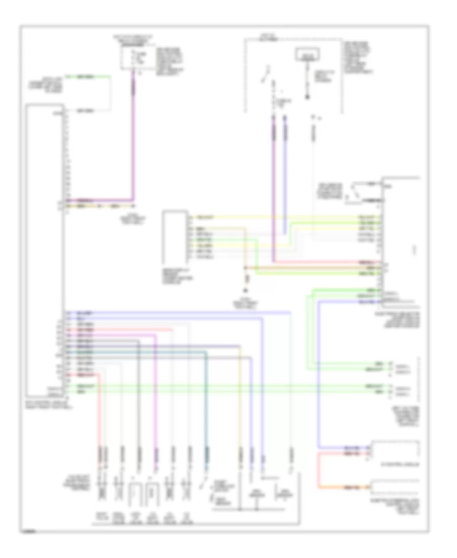
A/T Wiring Diagram, 5 Speed A/T for Mercedes-Benz E500 2003
List of elements for A/T Wiring Diagram, 5 Speed A/T for Mercedes-Benz E500 2003:
- (+)
- (-)
- 1-2/ 4-5 valve
- 2-3 shift valve
- 3-4 shift valve
- Can-c h
- Can-c l
- Circuit 87 relay, chassis
- Data link connector (dlc) (lower left side of dash)
- Di control module
- Diag
- Driver side sam control module with fuse & relay module (left rear of eng compt)
- Driver side sam control module with fuse/relay module (left rear of engine compartment)
- Electric steering lock control module (left front footwell)
- Electronic selector lever module control module (center console)
- Etc control module (right front footwell)
- Fuse 45 7.5a
- Fuse 7.5a
- Gear display sensor (under center console)
- Gnd
- Hot at all times
- Hot with circuit 87 relay chassis energized
- Keyless go start/stop pushbutton (if equipped)
- Left voltage distributor connector (left front door sill)
- Lock up valve
- Modu- lator valve
- Nca
- Rpm sensor
- Shift valve
- Sig
- Solid state
- Start interlock switch
- Temp sensor
- Valve unit (electronic transmission control)
- W15/1 (right front footwell)
 Čeština
 Dansk
Dansk Deutsch
 Ελληνικά
 English
 English
 Español
 Suomi
Suomi Français
 Français
 עברית
עברית Hrvatski
 Magyar
 Italiano
 日本語
日本語 한국어
한국어 Nederlands
 Polski
 Português
 Português
 Română
 Русский
 Slovenčina
 Svenska
 Türkçe
 中文 (中国)
 Slovenščina