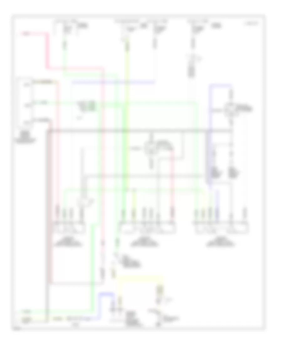
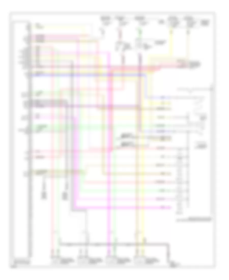
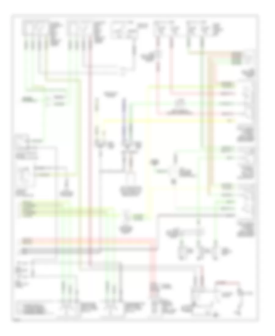
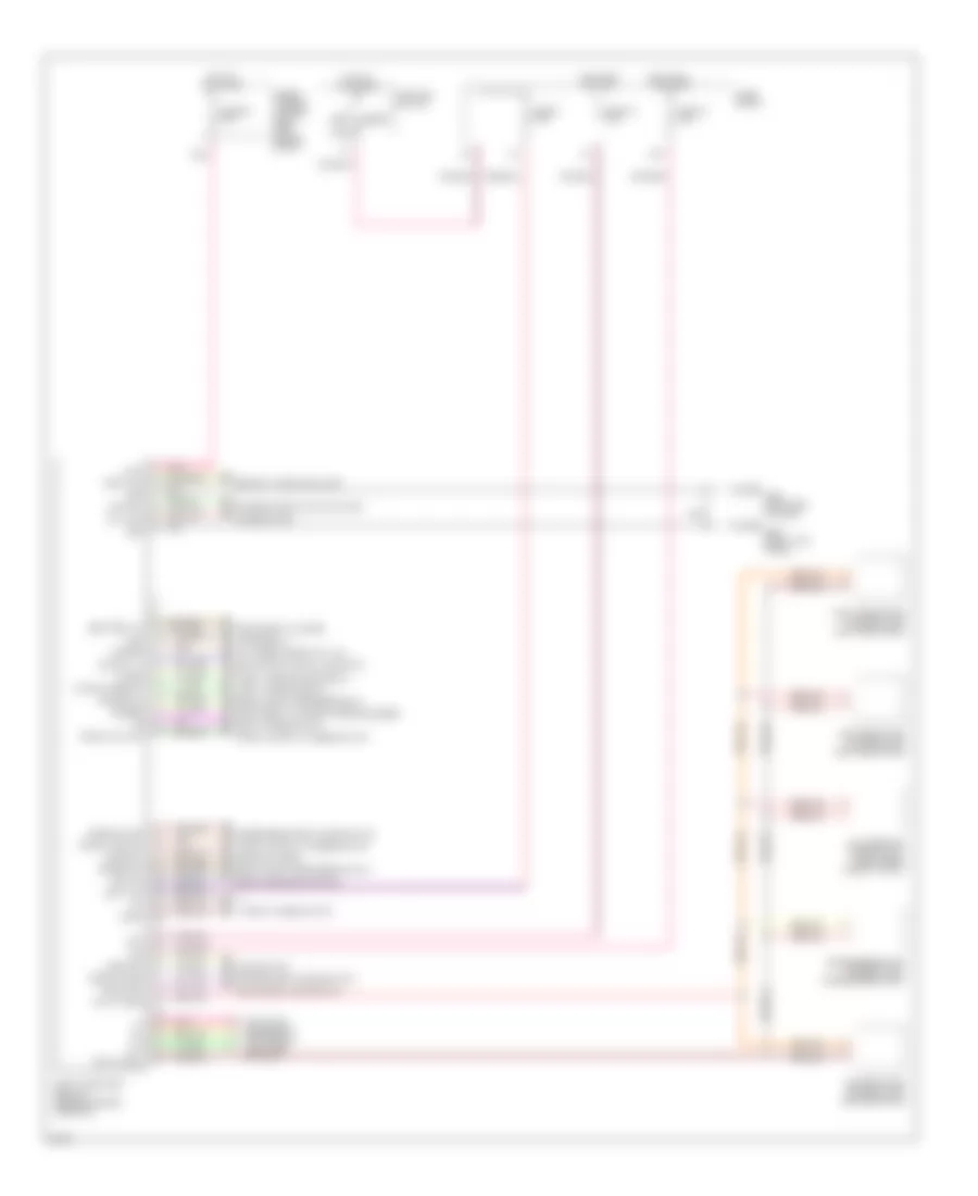
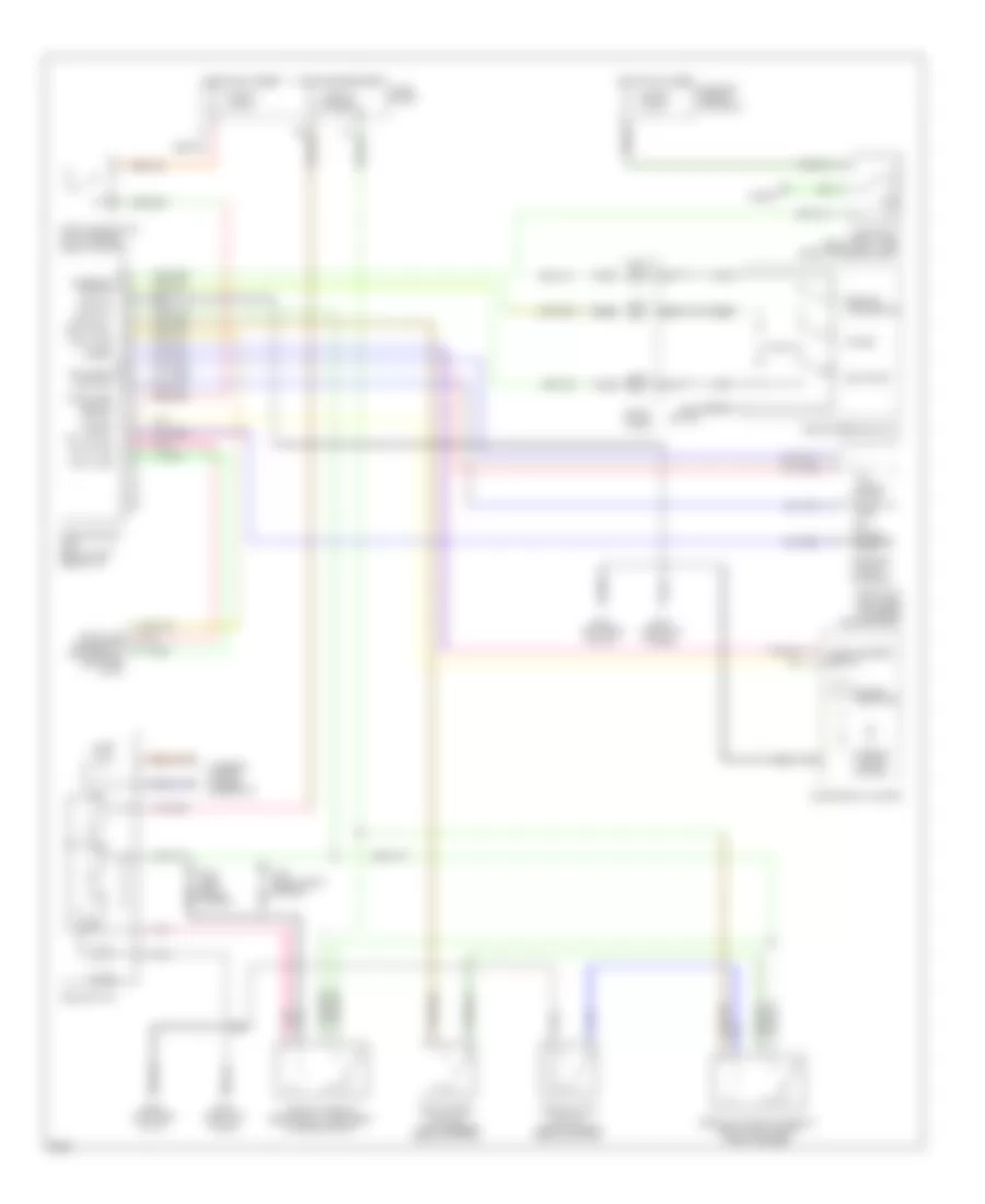
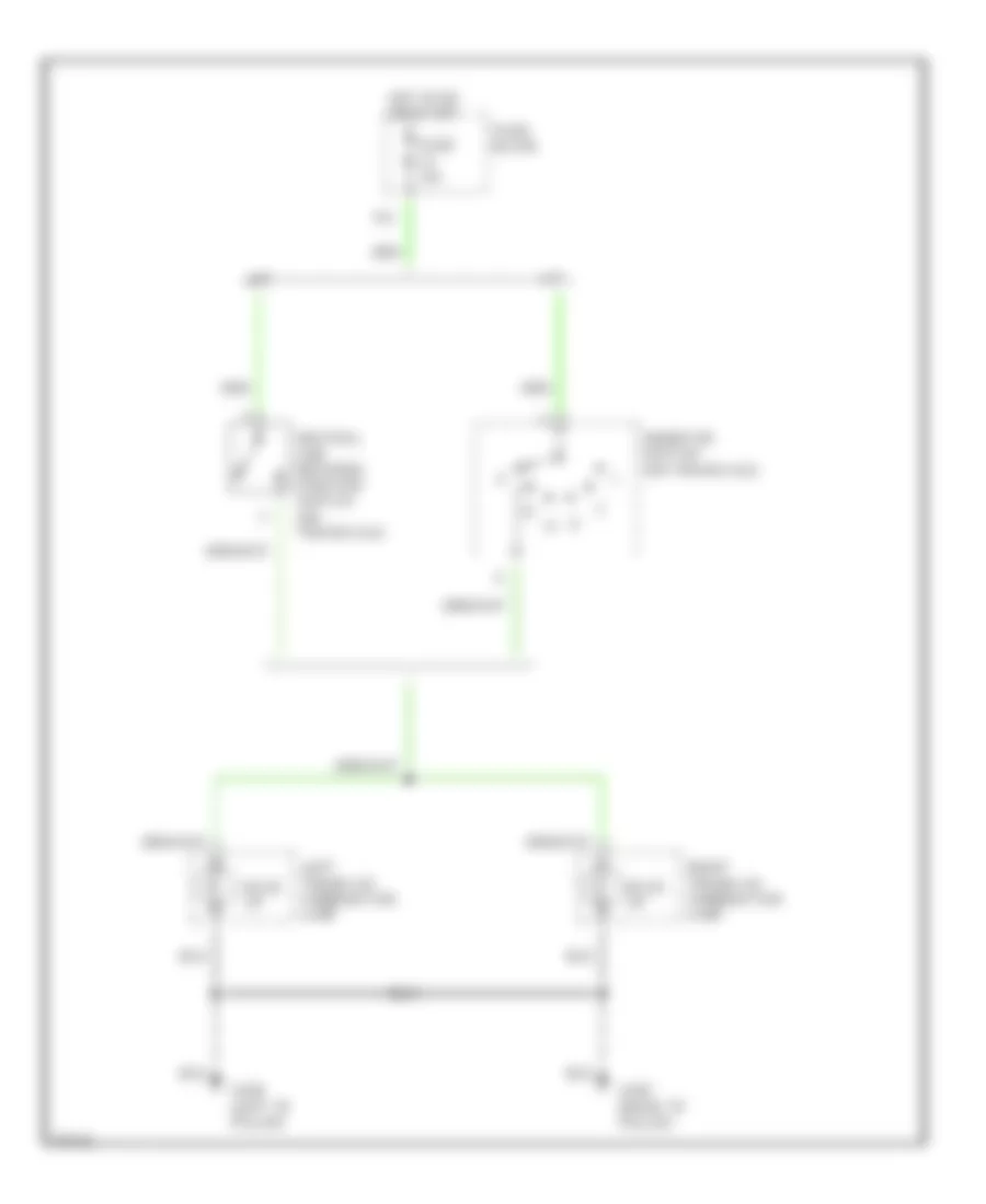
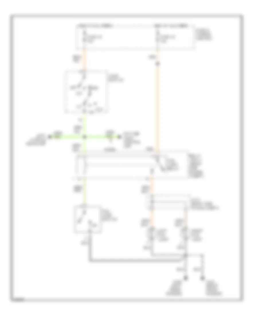
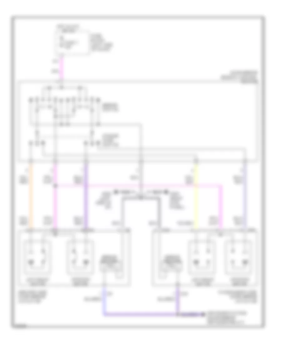
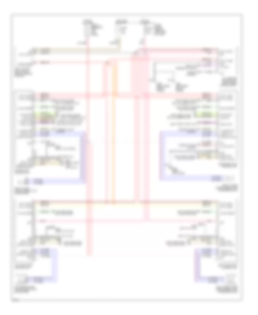
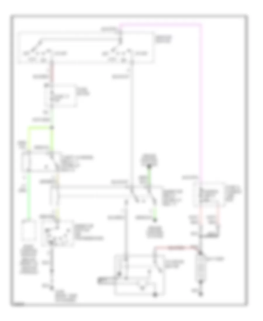
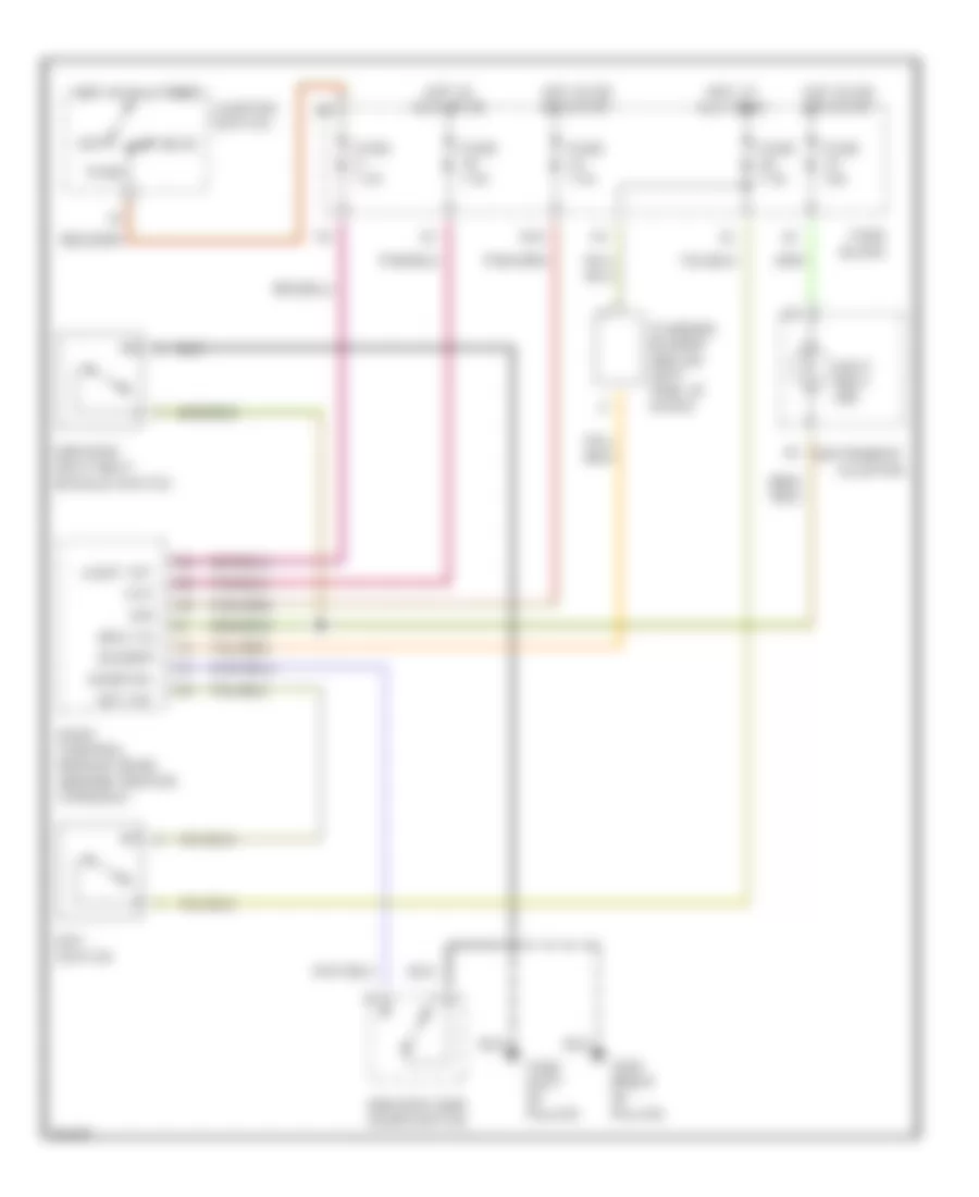
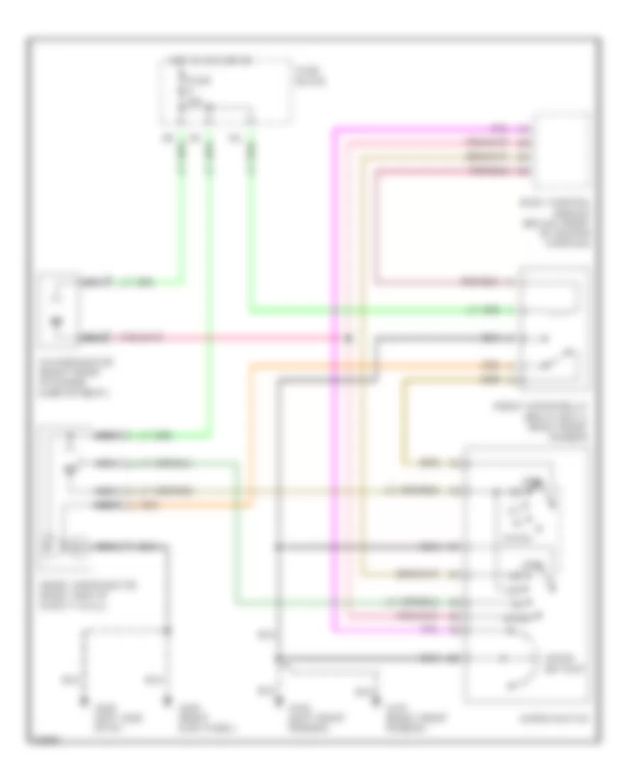
AIR CONDITIONING
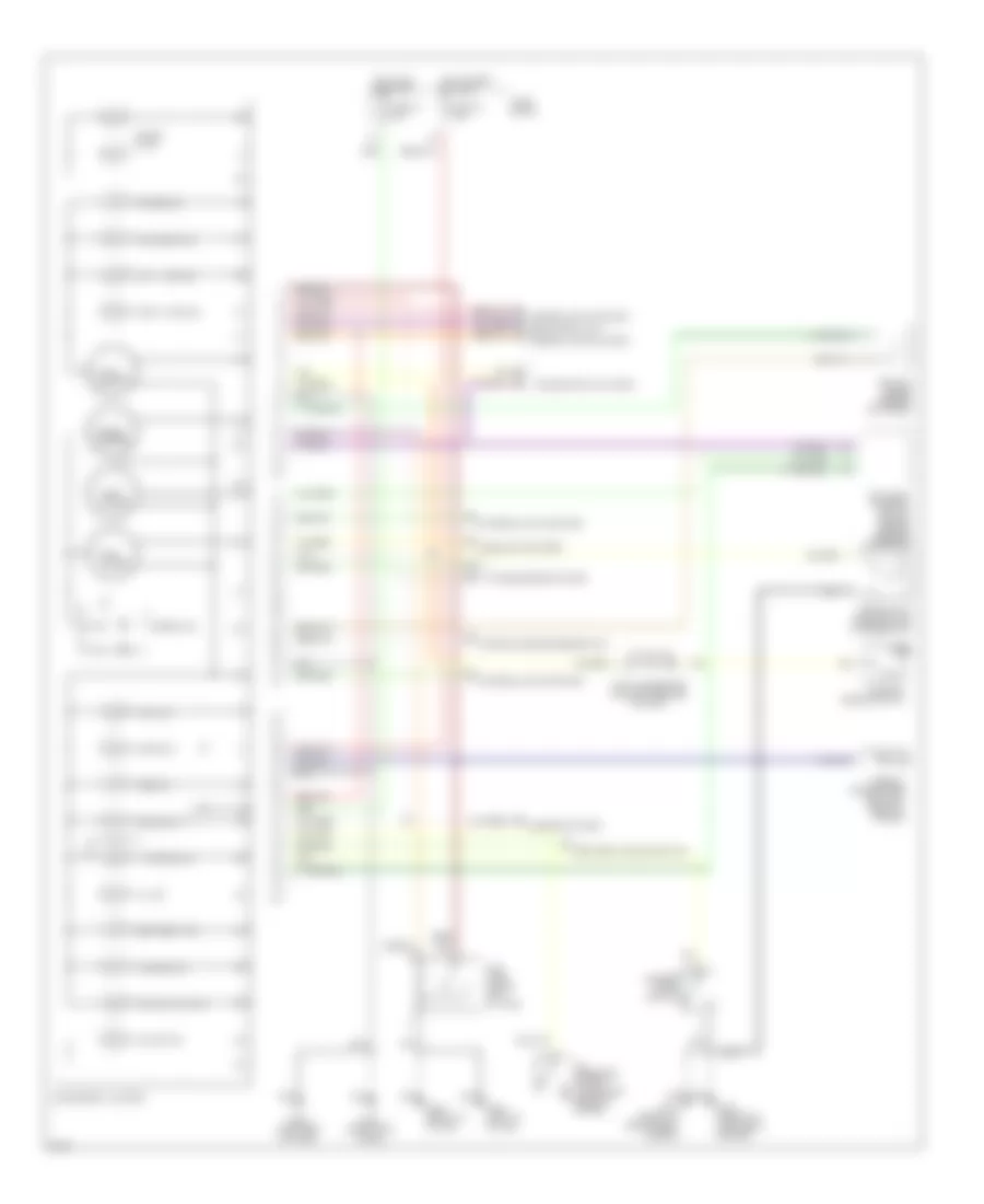
Air Conditioning Wiring Diagrams (1 of 2) for Infiniti I30 t 1997
 https://portal-diagnostov.com/license.html
Automotive Electricians Portal FZCO
Automotive Electricians Portal FZCO
https://portal-diagnostov.com/license.html
https://portal-diagnostov.com/license.html
Automotive Electricians Portal FZCO
Automotive Electricians Portal FZCO
List of elements for Air Conditioning Wiring Diagrams (1 of 2) for Infiniti I30 t 1997:
- (center of i/p)
- (left front of engine)
- (left side
- (right de-
- (right side kick panel)
- (right side of i/p)
- +5v
- 10k
- 11s
- 1994 vftc c
- 20% fre/fre
- A/c auto amplifier (below front of center console)
- A/mix pbr
- Air mix door motor
- Amb sens
- Ambient sensor (center front
- B/l
- B/l foot/def
- Blower motor
- Cold/hot
- Comp
- Def
- Engine control module (right frt of eng compt)
- F/d
- F/d def
- Fan control amp
- Fan f/b
- Fan gate
- Fascia)
- Ficd
- Foot
- Froster grille)
- Fuse 15a
- Fuse 7.5a
- Fuse block
- G202
- G203
- Hot in on
- I/p)
- Ign
- In vehicle sensor (right side
- Incar sens
- Intake door motor
- Intake sens
- Intake sensor (right side
- Interior lights system
- K/d clk
- K/d rx
- K/d tx
- Mode door motor (center of i/p)
- Of i/p)
- Or start
- Pnk
- Position switch
- Push control unit (center of i/p)
- Rec/fre
- Red/20%fre
- Sens gnd
- Sun sense
- Sunload sensor
- Tasw
- Thermal transmitter
- Thermo amp
- Triple pressure switch (left front of engine compt)
- Vent
- Vent b/l
- Vent/def
- Vent/foot/def
- W/t sens
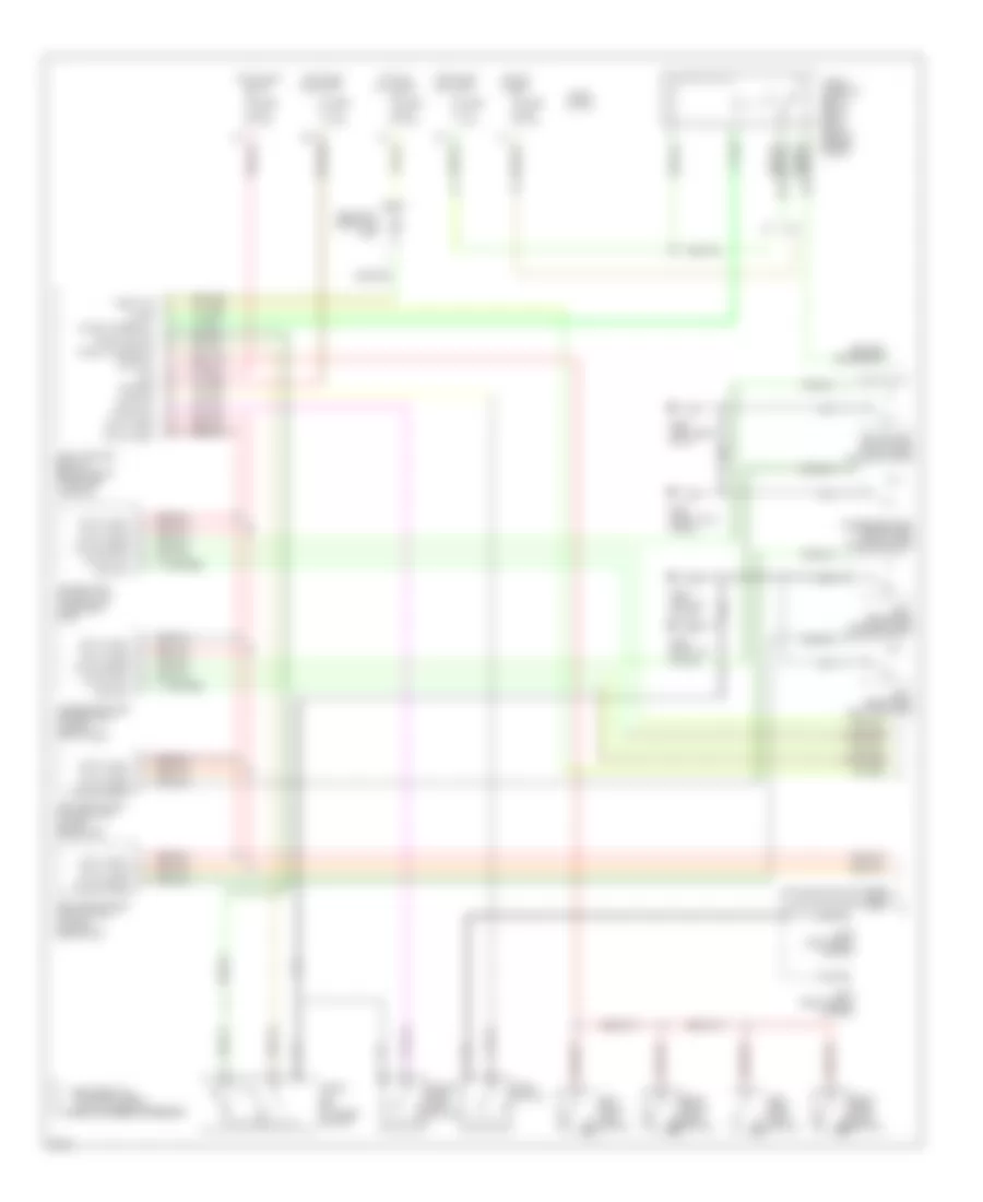
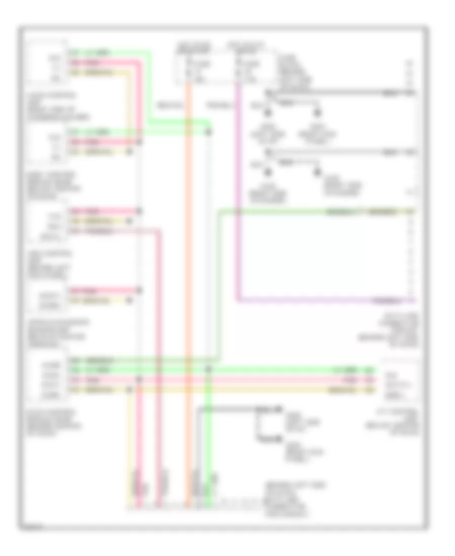
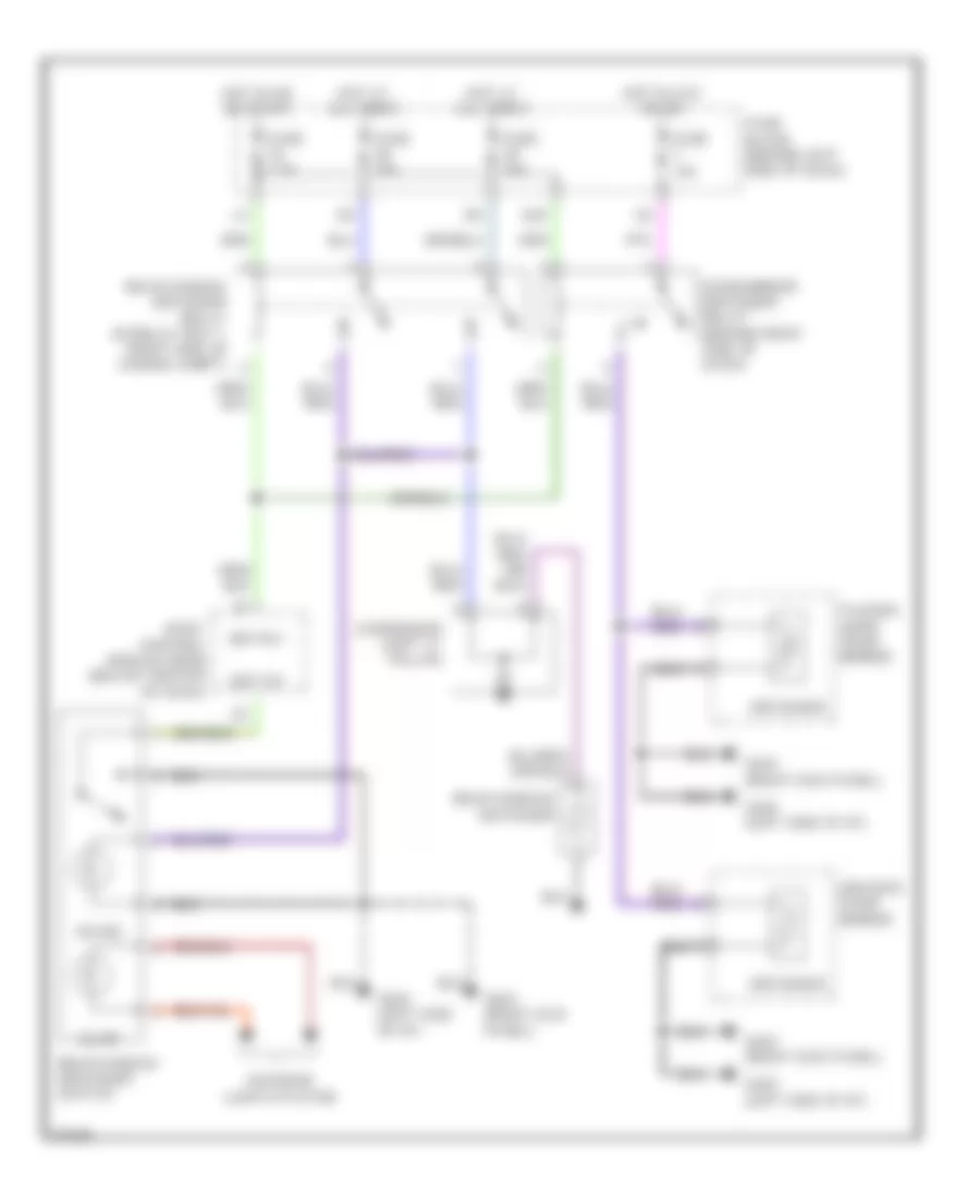
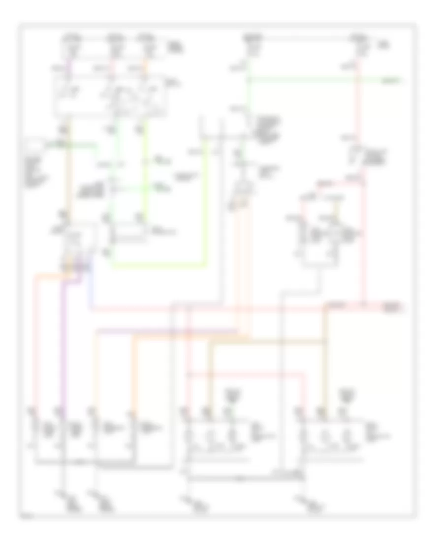
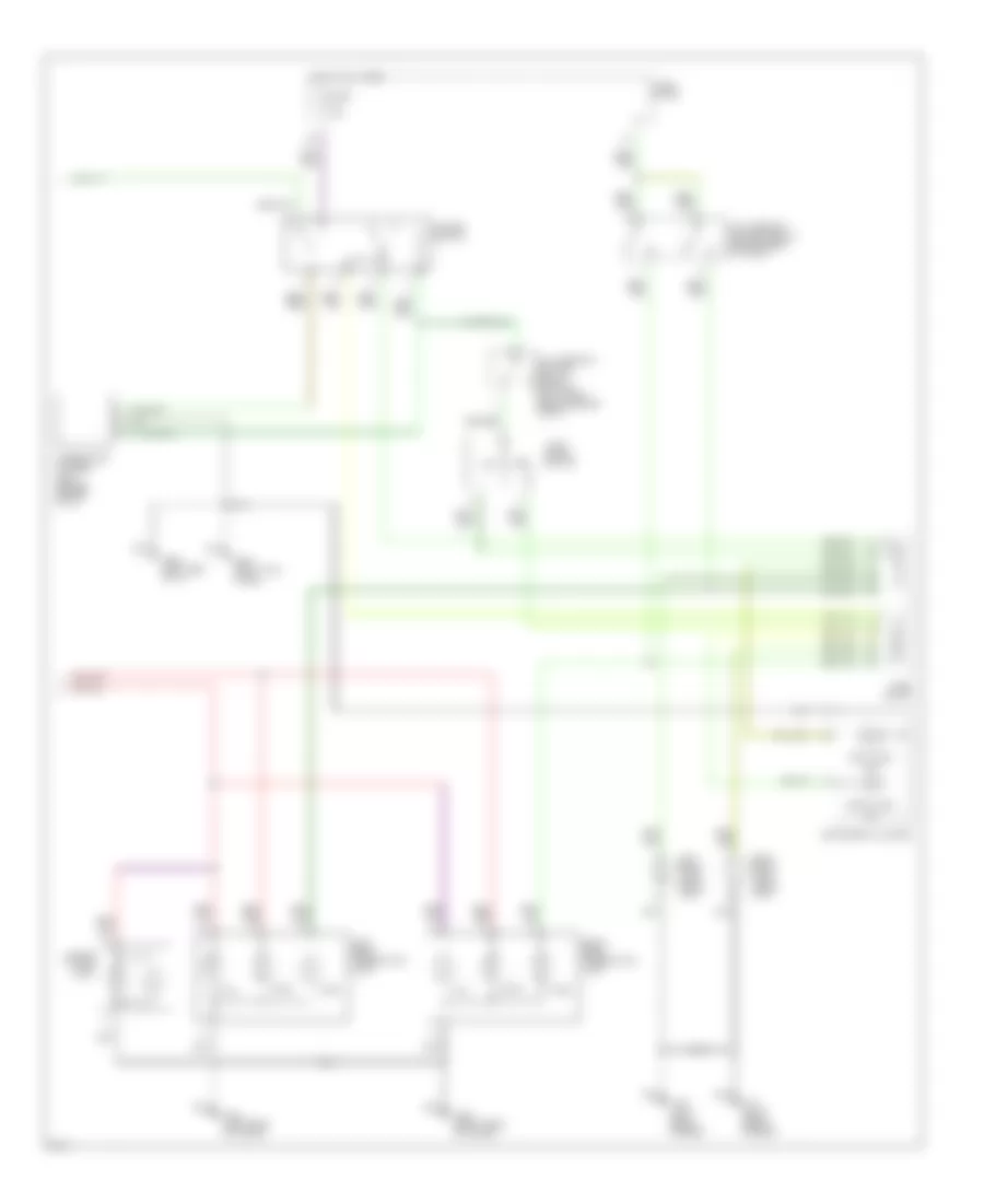
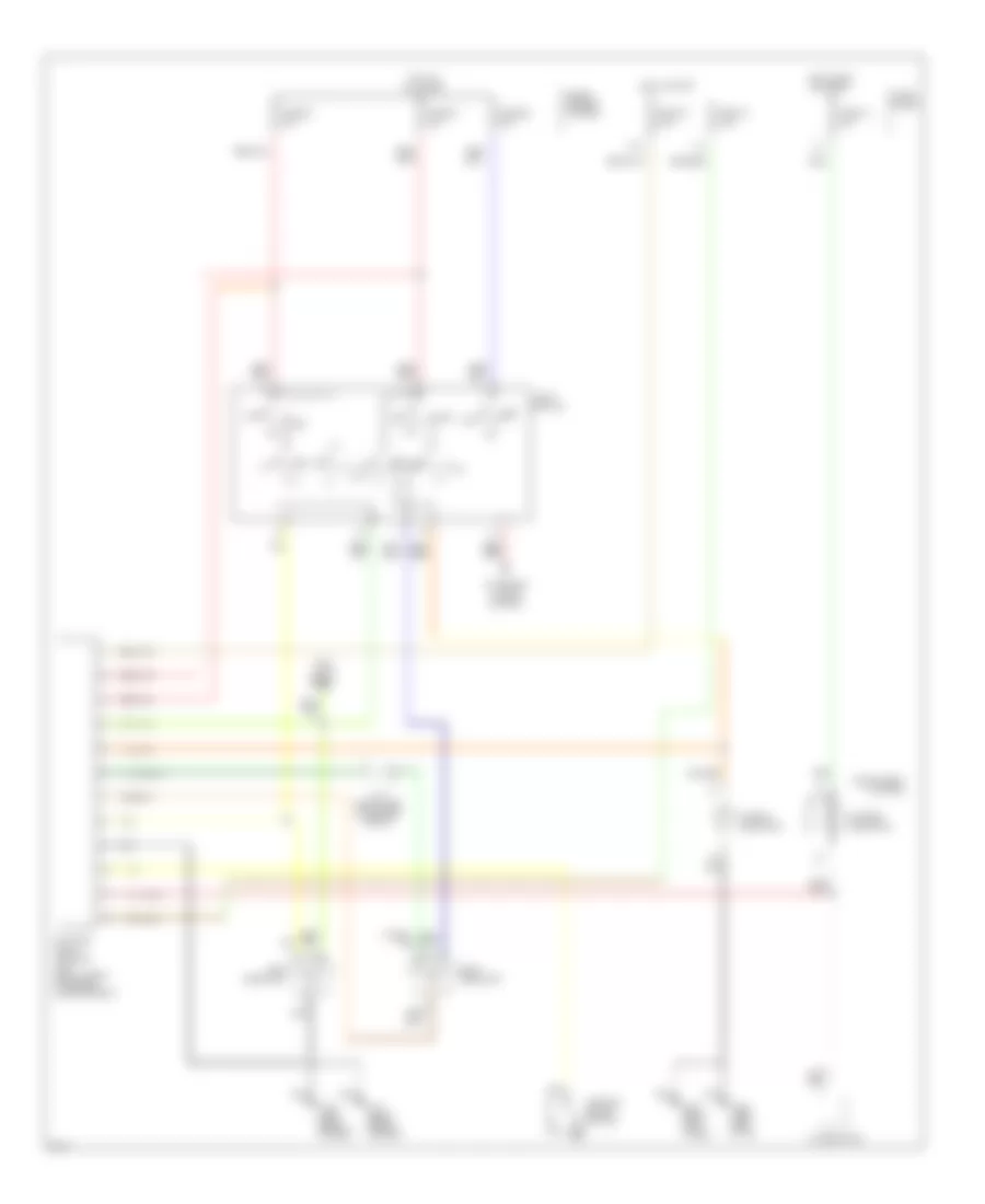
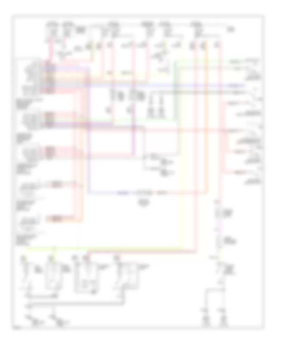
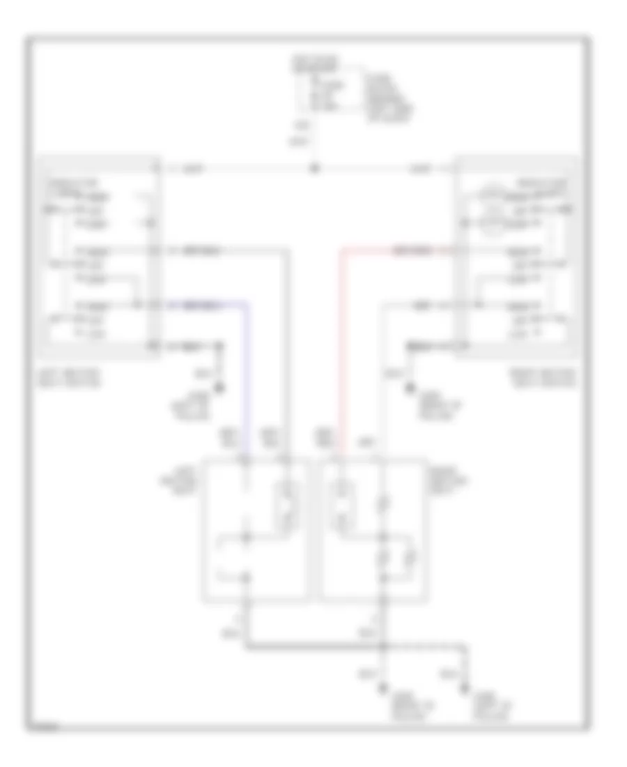
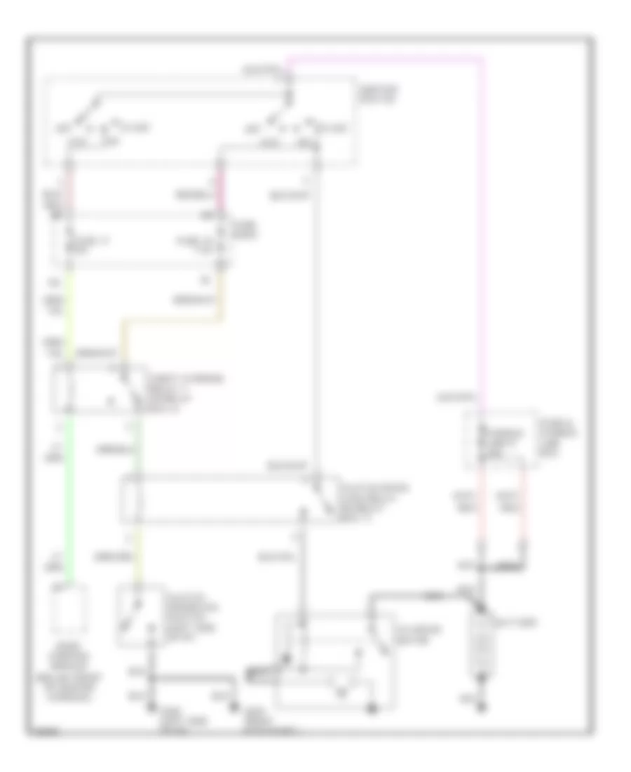
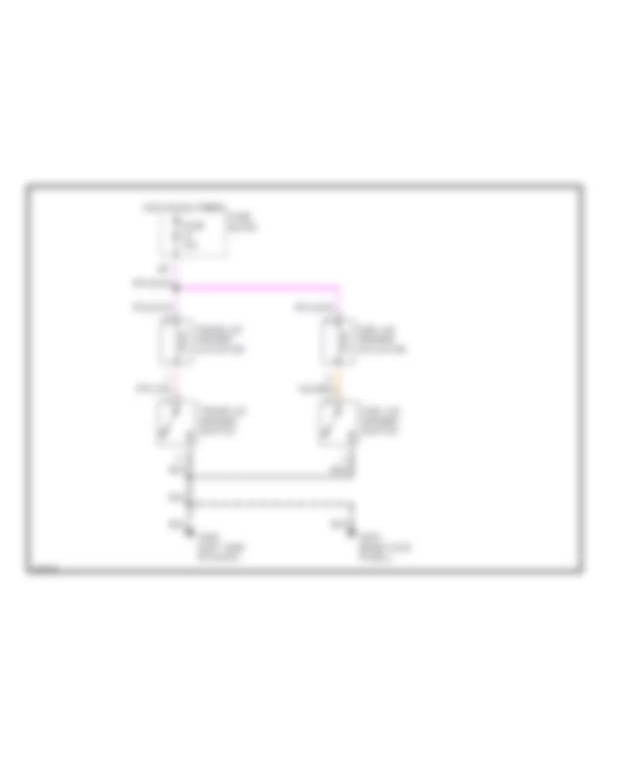
Air Conditioning Wiring Diagrams (2 of 2) for Infiniti I30 t 1997
List of elements for Air Conditioning Wiring Diagrams (2 of 2) for Infiniti I30 t 1997:
- 16l
- 1994 vftc c
- A/c compressor clutch
- A/c relay (relay box 1, right side of engine compt)
- Acrly
- Cooling fan motor 1
- Cooling fan motor 2
- Cooling fan relay 1 (relay box 2, left front of engine compt)
- Cooling fan relay 2 (relay box 1, right front of engine compt)
- Cooling fan relay 3 (relay box 1, right front of engine compt)
- Diode
- Engine control module (right front side of eng compt)
- Fuse 7.5a
- Fuse 17 10a
- Fuse block
- Fusible link d 30a
- Fusible link e 30a
- Fusible link box
- G100 (left front of engine compt)
- G101 (right front of engine compt)
- Hot at all times
- Hot in on and start
- Idle air control valve (left rear of engine compartment)
- J/c
- J/c 3
- J/c 7
- Pnk
- Rfrh
- Rfrl
ANTI-LOCK BRAKES
Anti-lock Brake Wiring Diagrams for Infiniti I30 t 1997
List of elements for Anti-lock Brake Wiring Diagrams for Infiniti I30 t 1997:
- (left front fender)
- (right front fender)
- Abs control actuator (left rear of engine compartment)
- Abs control unit (left kick panel)
- Abs warning lamp
- Bls
- Data link connector (left side
- Diag l
- Fl in
- Fl out
- Fl ss gnd
- Flss
- Fr in
- Fr out
- Fr ss
- Fr ss gnd
- Fuse 10 15a
- Fuse 13 10a
- Fuse and fusible link box
- Fuse block
- Fusible link g 30a
- Fusible link i 30a
- G100
- G101
- G202 (left kick panel)
- G202 (left side of i/p)
- G203 (right kick panel)
- Gnd
- Gnd1
- Gnd2
- Hot at all times
- Hot in on or start
- Instrument cluster
- Left front wheel speed sensor
- Left rear wheel speed sensor
- Motor relay
- Nca
- Of i/p)
- Pnk
- Red
- Right front wheel speed sensor
- Right rear wheel speed sensor
- Rl in
- Rl out
- Rl ss
- Rl ss gnd
- Rr in
- Rr out
- Rr ss
- Rr ss gnd
- Rxd
- Sila
- Solenoid valve relay
- Stop lamp switch
- Txd
ANTI-THEFT
Anti-theft Wiring Diagram (1 of 2) for Infiniti I30 t 1997
List of elements for Anti-theft Wiring Diagram (1 of 2) for Infiniti I30 t 1997:
- (left "b" pillar)
- (right "b" pillar)
- (right kick panel)
- 10g
- 16l
- A/t
- Acc
- Alarm
- Between full stroke & normal
- Body control module (below front of center console)
- Data line a
- Data line b
- Door sw
- Driver door control unit (in driver's door)
- Driver side front door lock actuator
- Fuse 10a
- Fuse 7.5a
- Fuse block
- G100 (left front fender)
- G101 (right front fender)
- G202 (left side of i/p)
- G203
- G305
- G308
- Hood sw
- Hood switch
- Hot at all times
- Hot in acc or on
- Hot in on or start
- Hot in start
- Key cylinder withdrawn
- Left front door switch
- Left rear door control unit (in left rear door)
- Left rear door lock actuator
- Left rear door switch
- Lock sw
- M/t
- Passenger door control unit (in right front door)
- Passenger side front door lock actuator
- Right front door switch
- Right rear door control unit (in right rear door)
- Right rear door switch
- Security indicator lamp
- Start interrupt
- Theft ind
- Theft warning relay (relay box 2, right side of engine compt)
- Trunk lid key cylinder switch
- Trunk room lamp switch
- Trunk sw
- Trunk tamper sw
- Trunk unlock
- Unlock sens
- Unlock sw
Anti-theft Wiring Diagram (2 of 2) for Infiniti I30 t 1997
List of elements for Anti-theft Wiring Diagram (2 of 2) for Infiniti I30 t 1997:
- stroke & normal
- stroke & normal unlock-between full
- (right kick panel)
- (right side of engine compartment)
- A/t
- Acc
- Ant
- Battery
- Canada
- Clutch interlock relay (m/t) (relay box 1, left front of engine compt)
- Clutch interlock switch (on pedal support)
- Data line a
- Data line b
- Daytime running light control unit (right front of engine compt)
- Driver side front door key cylinder switch
- Fuse 10a
- Fuse 15a
- Fuse 7.5a
- Fuse and fusible link box
- G120 (right side of engine)
- G202 (left side of i/p)
- G203
- Headlights system
- High horn
- Horn relay (in relay box 1, left front of engine compt)
- Horns system
- Hot at all times
- Ignition switch
- Inhibitor relay (a/t) (relay box 1, left front of engine compt)
- Inhibitor switch (on transaxle)
- J/c 2 (left side of engine compt)
- J/c 4 (left side of engine compartment)
- J/c 5 (right side of engine compt)
- J/c 6
- J/c 6 (right side of engine compt)
- J/c 8 (right side of engine compt)
- Left head- lamp
- Lock
- Lock-between full
- Low horn
- M/t
- Multi remote control unit (right rear of trunk)
- Nca
- Passenger side front door key cylinder switch
- Right head- lamp
- Run
- Start
- Starter motor
- Theft warning horn
- Theft warning horn relay (in relay box 2, right side of engine compartment)
- Theft warning lamp relay (in relay box 2, right side of engine compartment)
- Usa
- Window antenna
BODY COMPUTER
Body Computer Wiring Diagrams for Infiniti I30 t 1997
List of elements for Body Computer Wiring Diagrams for Infiniti I30 t 1997:
- 10g
- Acc
- Alarm
- Amp
- Bat
- Body computer
- Buzzer
- Clk
- Data line a
- Data line b
- Data link connector for consult (left side of dash)
- Door locks (key switch)
- Door sw
- Door sw (as)
- Door sw (dr)
- Door switches
- Driver's door control unit (driver's door)
- Driver's door lock actuator
- Driver's front door switch
- Front wiper switch
- Fuse & fusible link box (right side engine compt)
- Fuse 12 7.5a
- Fuse 19 7.5a
- Fuse 5 7.5a
- Fuse 56 7.5a
- Fuse block
- G202 (left side of dash)
- G203 (right kick panel)
- Gnd
- Hazard
- Head
- Hood sw
- Hood switch
- Hot at all times
- Hot in on
- Hot in on or acc
- Ign
- Ign key ill
- Ignition key hole illumination
- Instrument cluster
- Instrument cluster (warning buzzer)
- Int
- Int lamp
- Interior lamp
- Key sw
- Left rear door control unit (left rear door)
- Light 1st
- Lighting switch
- Lock sw
- Module (behind center console)
- Multi-remote control unit (right rear side of trunk)
- Multi-remote relays 1 & 2
- Off
- Or start
- Park
- Passenger's door control unit (passenger's door)
- Passenger's front door switch
- Pnk
- Rear window defogger relay
- Rear window defogger switch
- Right rear door control unit (left rear door)
- Rr def sw
- Seat belt in
- Security indicator lamp
- Start interupt
- Theft ind
- Theft warning horn relay
- Theft warning relay
- Trunk lid key cylinder switch
- Trunk room lamp switch
- Trunk sw
- Trunk tamp sw
- Trunk unlk sw
- Wash
- Wiper relay
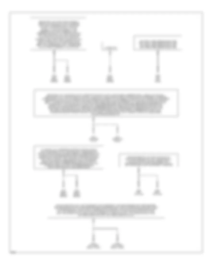
COMPUTER DATA LINES
Computer Data Lines for Infiniti I30 t 1997
List of elements for Computer Data Lines for Infiniti I30 t 1997:
- (behind left side of dash) data link connector for consult
- A/t control unit (below center of dash)
- Abs control unit (behind left kick panel)
- Air bag diagnosis sensor unit (rear of center console)
- Ascd control unit (right side of steering column)
- Body control module (bcm) (below center of dash)
- Clk
- Data link connector for gst (behind left side of dash)
- Diag l
- Eccs control module (ecm) (behind center of dash)
- Fuse 10a
- Fuse 7.5a
- Fuse block (behind left side of dash)
- G120 (right side of engine)
- G202 (left side of i/p)
- G203 (right kick panel)
- Hot in acc or on
- Hot in on or start
- In(rx)
- Kline
- Out(tx)
- Pnk
- Rxd
- Scicl
- Scirx
- Scitx
- Sssrx
- Ssstx
- Txd
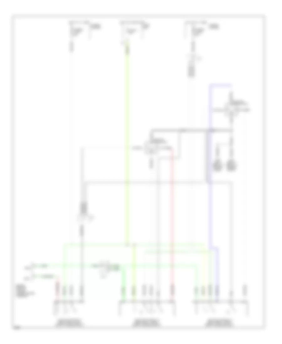
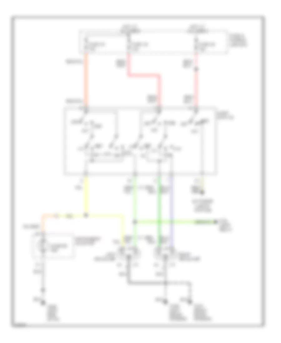
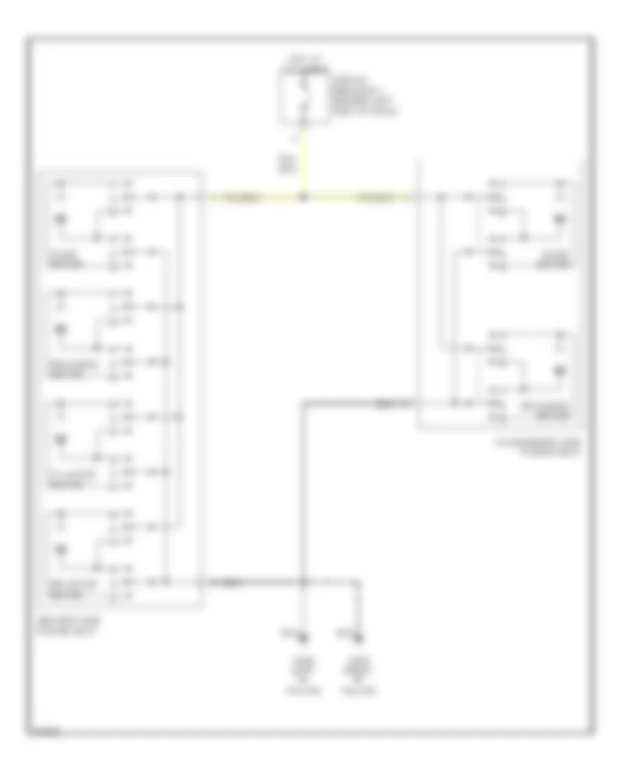
COOLING FAN
Cooling Fan Wiring Diagram for Infiniti I30 t 1997
List of elements for Cooling Fan Wiring Diagram for Infiniti I30 t 1997:
- 16l
- Cooling fan motor 1
- Cooling fan motor 2
- Cooling fan relay 1 (relay box 2, left front of engine compt)
- Cooling fan relay 2 (relay box 1, right front of engine compt)
- Cooling fan relay 3 (relay box 1, right front of engine compt)
- Engine control module (under center console)
- Fuse 17 10a
- Fuse box
- Fusible link d 30a
- Fusible link e 30a
- Fusible link box
- G100 (left front of engine compt)
- G101 (right front of engine compt)
- Hot at all times
- Hot in on and start
- J/c
- J/c 3
- Rfrh
- Rfrl
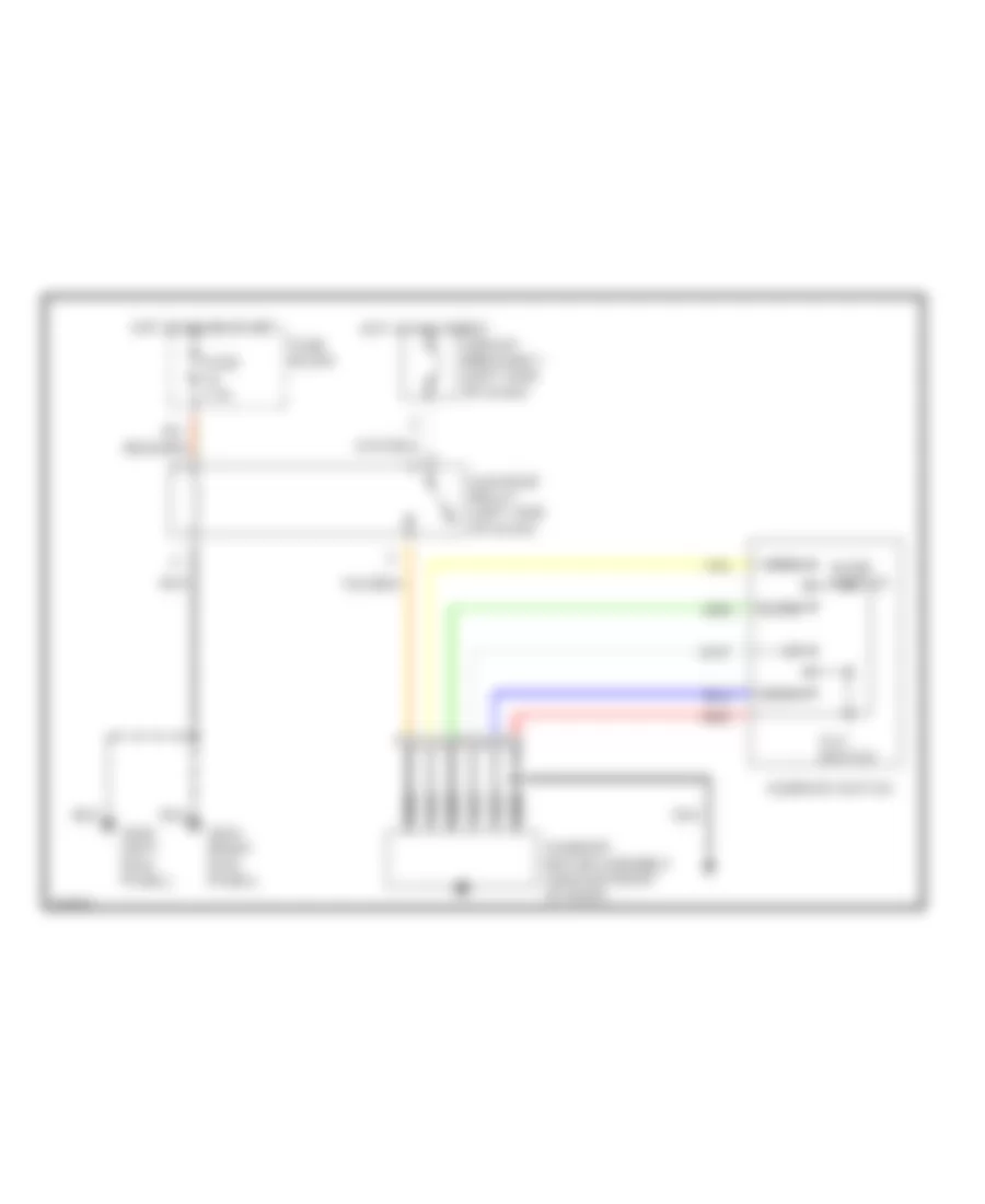
CRUISE CONTROL
Cruise Control Wiring Diagram, A/T for Infiniti I30 t 1997
List of elements for Cruise Control Wiring Diagram, A/T for Infiniti I30 t 1997:
- A/t control unit (left kick panel)
- Act. cntrl
- Actuator control
- Air valve solenoid
- Ascd cancel switch (brake pedal support)
- Ascd control unit (below left side of i/p)
- Ascd hold relay (relay box 1, left front of engine compt)
- Ascd pump (left rear of engine compartment)
- Ascd steering switch
- Ascd sw.
- Ascd switch
- Cancel
- Crs. cancl
- Cruise
- Cruise indicator
- Cruise signal
- Data line
- Data link connector for consult (left side of i/p)
- Fuse 10 15 amp
- Fuse 12 7.5 amp
- Fuse 17 10 amp
- Fuse 64 15 amp
- Fuse and fusible link block
- Fuse block
- G100 (left front fender)
- G101 (right front fender)
- G120 (right side of engine)
- G202 (left side of i/p)
- G203 (left kick panel)
- Ground
- Horn relay (relay box 1, left front of engine compt)
- Horn switch
- Horns
- Hot at all times
- Hot in on or start
- Illum.
- Inhibitor relay (relay box 1, left front of engine compartment)
- Inhibitor switch (left side of transmission)
- Instrument cluster
- Interior lights system
- Interior lights system (rheostat)
- Nca
- Od cut signal
- Off
- On ind.
- Pnk
- Release valve solenoid
- Resume/ accelerate
- Set/coast
- Speed
- Spiral cable
- Steering switch
- Stop lamp switch (top of brake pedal support)
- Stop lamp switch od cut
- Theft warning relay 2 (relay box-2, right front fender)
- Vacuum motor
- Vehicle speed output
Cruise Control Wiring Diagram, M/T for Infiniti I30 t 1997
List of elements for Cruise Control Wiring Diagram, M/T for Infiniti I30 t 1997:
- Act. cntrl
- Actuator control
- Air valve solenoid
- Ascd cancel switch (top of brake pedal support)
- Ascd clutch switch (top of clutch pedal support)
- Ascd clutch switch relay (relay box 2, right front fender)
- Ascd control unit (below left side of i/p)
- Ascd hold relay (relay box 1, left front of engine compt)
- Ascd pump (left rear of engine compartment)
- Ascd steering switch
- Ascd sw.
- Ascd switch
- Cancel
- Crs. cancl
- Cruise
- Cruise indicator
- Data line
- Data link connector for consult (left side of i/p)
- Fuse 10 15 amp
- Fuse 12 7.5 amp
- Fuse 64 15 amp
- Fuse and fusible link block
- Fuse block
- G100 (left front fender)
- G101 (right front fender)
- G202 (left side of i/p)
- G203 (left kick panel)
- Ground
- Horn relay (relay box 1, left front of engine compt)
- Horn switch
- Horns
- Hot at all times
- Hot in on or start
- Illum.
- Instrument cluster
- Interior lights system
- Interior lights system (rheostat)
- Nca
- Off
- On ind.
- Pnk
- Release valve solenoid
- Resume/ accelerate
- Set/coast
- Speed
- Spiral cable
- Steering switch
- Stop lamp switch (top of brake pedal support)
- Stop lamp switch od cut
- Vacuum motor
- Vehicle speed output
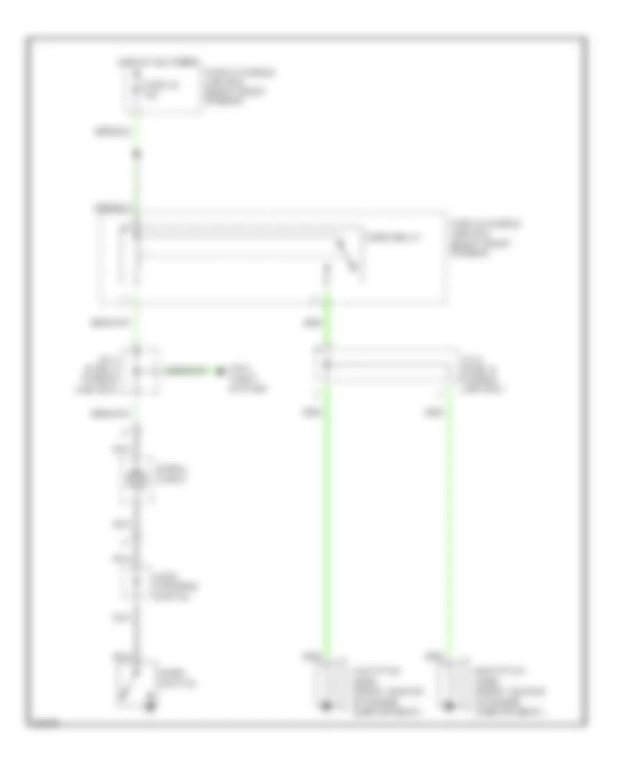
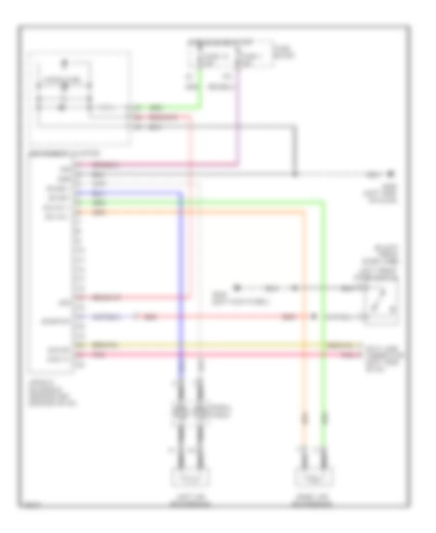
DEFOGGERS
Defogger Wiring Diagram for Infiniti I30 t 1997
List of elements for Defogger Wiring Diagram for Infiniti I30 t 1997:
- Body control module (bcm) (below center of dash)
- Condenser (left "c" pillar)
- Def rly
- Def sw
- Defogger
- Door mirror defogger relay (behind right side of dash)
- Driver's door mirror
- Fuse 10a
- Fuse 20a
- Fuse 7.5a
- Fuse block (behind left side of dash)
- G20
- G202 (left side of i/p)
- G203 (right kick panel)
- Hot at all times
- Hot in acc or on
- Hot in on or start
- Illum
- Interior lights system
- On ind
- Passen- ger's door mirror
- Rear window defogger
- Rear window defogger relay (in relay box 1, right side of engine compt)
- Rear window defogger switch
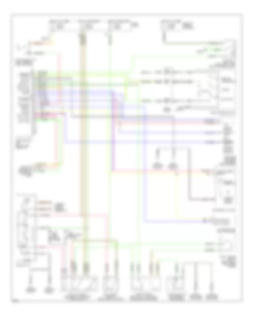
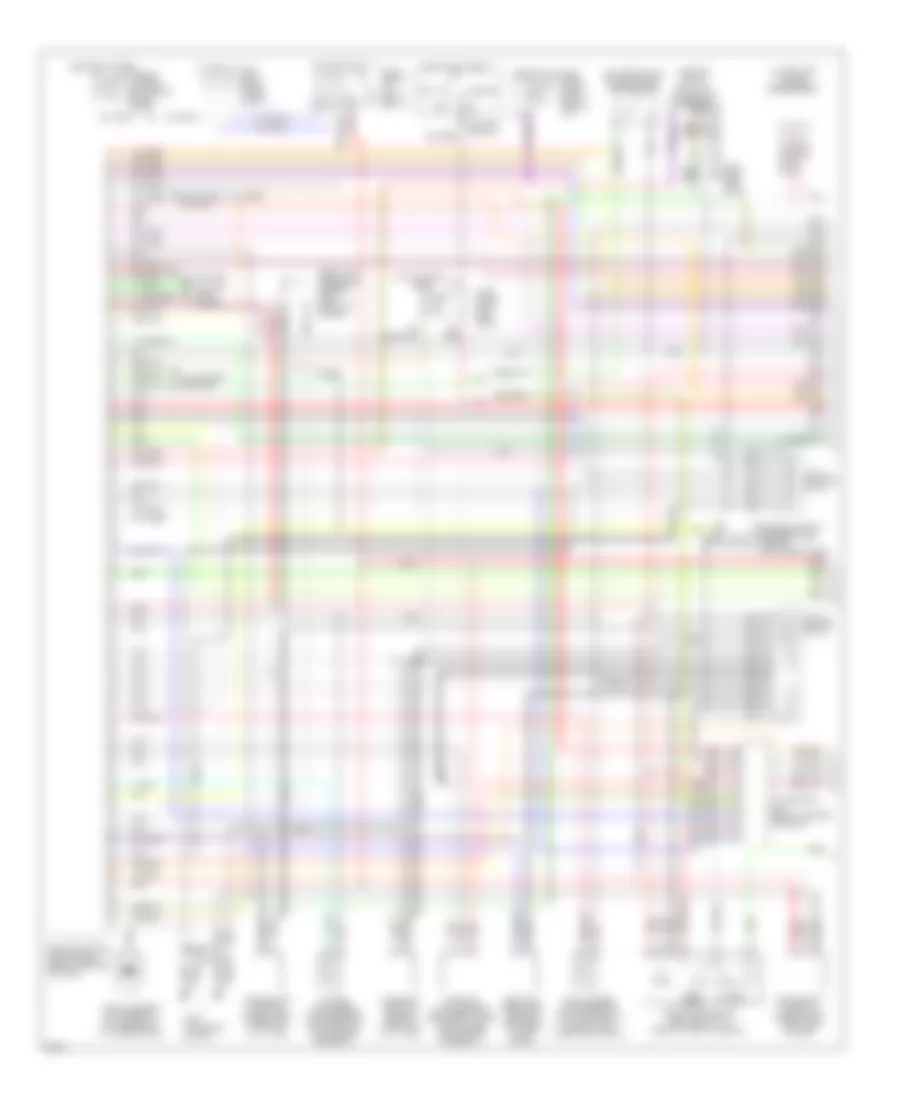
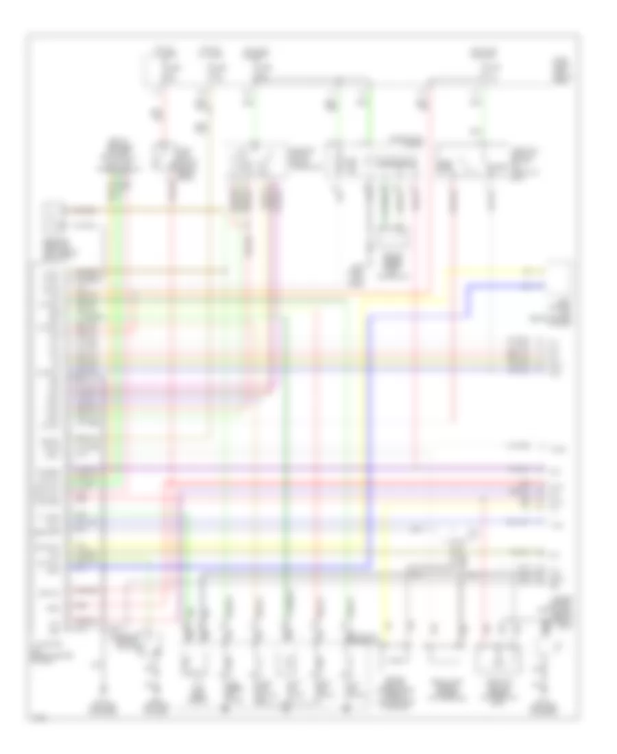
ENGINE PERFORMANCE
3.0L
3.0L, Engine Performance Wiring Diagrams (1 of 2) for Infiniti I30 t 1997
List of elements for 3.0L, Engine Performance Wiring Diagrams (1 of 2) for Infiniti I30 t 1997:
- (center of i/p) data link connector (for gst)
- (lower left of eng) engine mount
- (on transaxle) neutral posi- tion switch
- 10h
- A/c system
- A/t
- A/t control unit (below center console)
- Absolute pressure sensor (left front of engine)
- Acc
- Camshaft position sensor (front of oil filter)
- Closed
- Cooling fans system
- Crankshaft position sensor (pos) (left side of eng)
- Crankshaft position sensor (ref) (front of oil filter)
- Eccs relay (in relay box-1)
- Egr tem- perature sensor (left rear of eng compt)
- Engine control module (ecm) (below center of dash)
- Engine coolant temperature sensor (left side of eng)
- Fuel temper- ature sensor (fuel gauge unit) (in fuel tank, under rear seat)
- Fuse 7.5a
- Fuse 7.5a
- Fuse block (left side of i/p)
- Fusible link box (left front of eng compt)
- G125 (top front of eng)
- G202 (left side of i/p)
- Hot at all times
- Hot in start
- Ignition switch
- Instrument cluster system
- Intake air temper- ature sensor (mounted into air cleaner assembly)
- J/c-1 (left front of eng compt)
- J/c-11 (center of i/p)
- J/c-12 (center of i/p)
- Knock sensor (attached to top center of cylinder block)
- M/t
- Mass air flow sensor (between intake manifold and air cleaner assembly)
- Nca
- Off
- Or on
- Red
- Start
- Throttle position sensor/switch (side of throttle body)
- Wide open
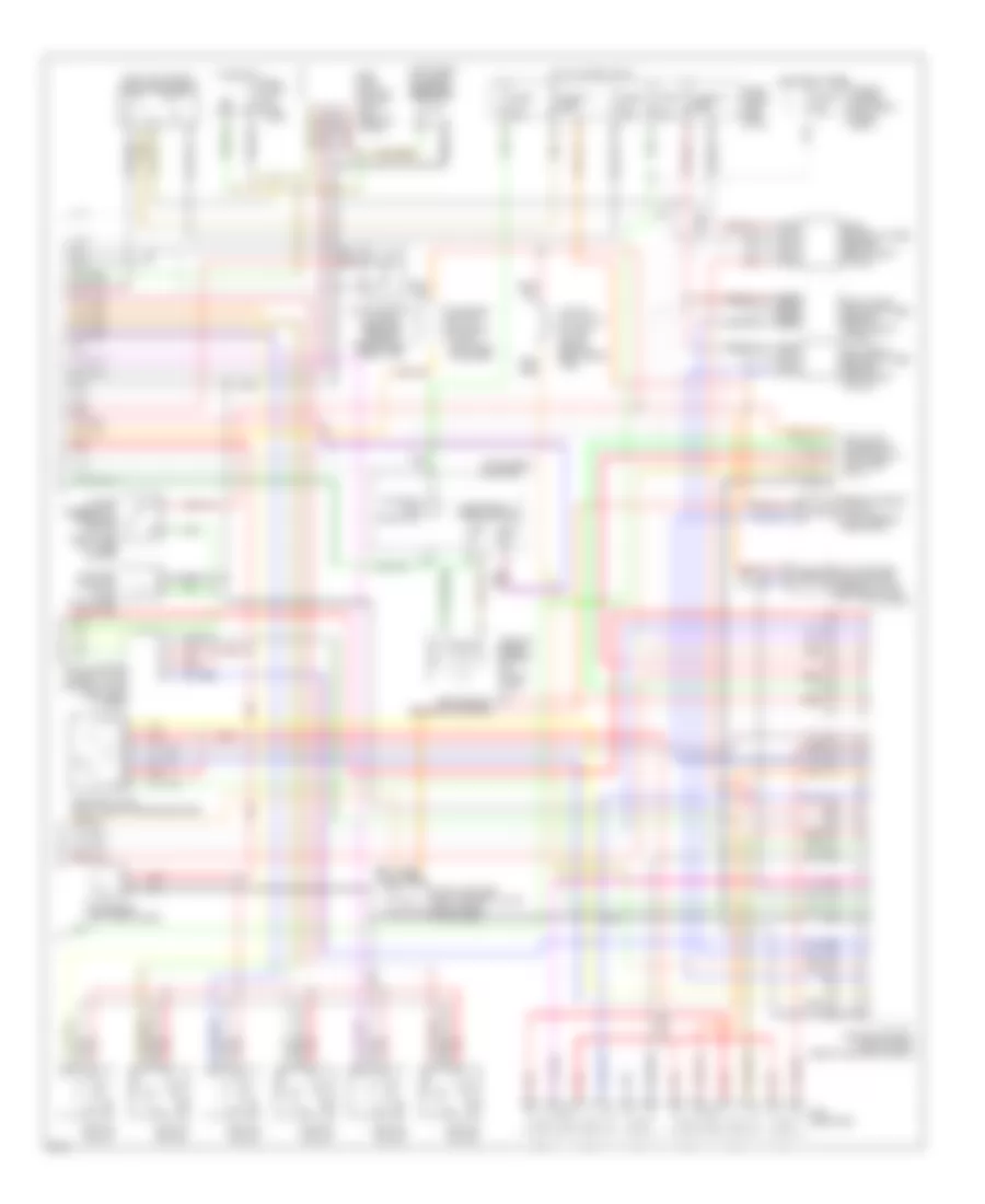
3.0L, Engine Performance Wiring Diagrams (2 of 2) for Infiniti I30 t 1997
List of elements for 3.0L, Engine Performance Wiring Diagrams (2 of 2) for Infiniti I30 t 1997:
- (left
- (left kick panel) fuel pump relay
- (left rear of trunk) dropping resistor
- 11q
- 17j
- 19g
- Condenser (left side of eng)
- Control
- Data link connector (for consult) (left side of i/p)
- Defogger or headlights system
- Egrc solenoid valve (left rear of eng compt)
- Electronic speedometer
- Engine control module (ecm) (below center of dash)
- Evap canister purge control solenoid valve (left side of eng)
- Evap canister purge volume control valve (left rear of eng)
- Evap canister vent control valve (right rear of vehicle)
- Evap control system pressure sensor (behind right rear tire)
- Fuel injectors
- Fuel pump
- Fuel pump (in fuel tank)
- Fuse 10a
- Fuse 15a
- Fuse 17 10a
- Fuse 34 15a
- Fuse 7.5a
- Fuse block (left side of i/p)
- Fusible link box (left front of eng compt)
- Hot at all times
- Hot in start or on
- Iacv-aac valve (right side of brake booster)
- Iacv-ficd solenoid valve (top of egr valve)
- Ignition coil #1
- Ignition coil #2
- Ignition coil #3
- Ignition coil #4
- Ignition coil #5
- Ignition coil #6
- Instrument cluster
- Left front heated oxygen sensor (left front of eng)
- Malfunc- tion indicator
- Map/baro switch solenoid valve (left side of engine)
- Module
- Nca
- Pnk
- Power steering oil pressure switch (right side of wiper motor)
- Rear heated oxygen sensor (right front of eng)
- Rear of
- Red
- Red/
- Right front heated oxygen sensor (right front of eng)
- Trunk)
- Vacuum cut valve bypass valve (behind right rear tire)
- Vehicle speed sensor (on trans- axle)
- Vss in
- Vss out
EXTERIOR LIGHTS
Back-up Lamps Wiring Diagram for Infiniti I30 t 1997
List of elements for Back-up Lamps Wiring Diagram for Infiniti I30 t 1997:
- 19j
- A/t
- Back up
- Fuse 10a
- Fuse block
- G305 (right "b" pillar)
- G308 (left "b" pillar)
- Hot in on or start
- Inhibitor switch (on transaxle)
- Left trunk lid combination lamp
- M/t
- Neutral and reverse position switch (on transaxle)
- Right trunk lid combination lamp
Exterior Lamps Wiring Diagram (1 of 2) for Infiniti I30 t 1997
List of elements for Exterior Lamps Wiring Diagram (1 of 2) for Infiniti I30 t 1997:
- 13s
- 1st
- 2nd
- Back- up
- Back-up lights circuit
- Canada
- Cornering lamp relay (in relay box 2, right side of engine compt)
- Cornering lamp switch
- Daytime running light control unit (right front of engine compt)
- Ftp
- Fuse & fusible link box
- Fuse 15a
- Fuse 7.5a
- Fuse block
- G100 (left front fender)
- G101 (right front fender)
- G305 (right "b" pillar)
- G308 (left "b" pillar)
- Headlights system
- High mounted stop light
- Hot at all times
- Hot in on or start
- Joint connector 6 (right front fender apron)
- Joint connector 9
- Left clear- ance light
- Left cornering light
- Left trunk lid combination light
- Light switch
- Off
- Right clear- ance light
- Right cornering light
- Right trunk lid combination light
- Stop
- Stop lamp switch (on pedal support)
- Tail
- Usa
- W/ spoiler
- W/o spoiler
Exterior Lamps Wiring Diagram (2 of 2) for Infiniti I30 t 1997
List of elements for Exterior Lamps Wiring Diagram (2 of 2) for Infiniti I30 t 1997:
- 10s
- 11j
- 12j
- 13q
- 14s
- Combination flasher unit (behind center of i/p)
- Fuse 10a
- Fuse block
- G100 (left front fender)
- G101 (right front fender)
- G202 (left side of i/p)
- G203 (right kick panel)
- G404 (left rear of trunk)
- G405 (right rear of trunk)
- Hazard switch
- Hot at all times
- Instrument cluster
- Left front turn signal light
- Left rear combination light
- Left turn ind
- License plate light
- Multi remote control relay 1 (center rear of trunk)
- Multi remote control relay 2 (in relay box 2, right side of engine compt)
- Right front turn signal light
- Right rear combination light
- Right turn ind
- Stop
- Tail
- Turn
- Turn signal switch
GROUND DISTRIBUTION
Ground Distribution Wiring Diagram for Infiniti I30 t 1997
List of elements for Ground Distribution Wiring Diagram for Infiniti I30 t 1997:
- A/t control unit, condenser, electronic control module, iacv-ficd solenoid valve 1, ignition coils, inhibitor switch, neutral position switch, power steering oil pressure switch, camshaft position sensor shield wire, crankshaft position sensor shield wire, left front heated oxygen sensor shield, right front heated oxygen sensor shield, knock sensor shield, mass air flow sensor shield, throttle position sensor shield, absolute pressure sensor shield, data link connector, fuel pump, fuel tank pressure sensor shield, rear heated oxygen sensor shield
- Abs control actuator, ascd hold relay, brake fluid level switch, left clearance light, right clearance light, cooling fan motor 1, cooling fan motor 2, cooling fan relay 2, cooling fan relay 3, left cornering light, right cornering light, cornering light relay, daytime light control unit, left front fog light, right front fog light, front fog light switch, left front turn signal light, right front turn signal light, front wiper switch, left headlight, right headlight, hood switch, theft warning horn relay, triple pressure switch, washer level switch, front wiper relay, a/c auto amp
- Abs control unit, od control switch, park position switch, shift lock solenoid, accessory relay, ascd clutch switch, ascd control unit, ascd main switch, ashtray illumination, audio amp relay, body control module, blower relay, cigarette lighter socket, clock, clutch interlock switch, combination flasher unit, instrument cluster, data link connector, door mirror remote control switch, fan control amp, front wiper motor, fuel filler lid opener switch, glove box light switch, ignition relay, illumination control switch, intake door motor, mode door motor, push control unit, rear window defogger switch, sunroof relay, iacv-ficd solenoid valve 2, left door mirror defogger, right door mirror defogger, driver door lock control unit, driver side key cylinder switch, passenger side key cylinder switch, left front door lock actuator, right front door lock actuator, left front door speaker, right front door speaker, passenger door control unit, left front door speaker shield wire, right front door speaker shield wire, trunk lid opener switch, spot light, integrated homelink transmitter, left vanity mirror illumination, right vanity mirror illumination, inside mirror, air bag diagnosis sensor unit
- Alternator
- Dropping resistor, left front door switch, right front door switch, fuel tank gauge unit, fuel pump control module, handset, left heated seat switch, right heated seat switch, left heated seat, right heated seat, telephone
- G100 (left front fender)
- G101 (right front fender)
- G120 (right side of engine)
- G200 (left kick panel)
- G202 (left side of i/p)
- G203 (right kick panel)
- G305 (right "b" pillar)
- G308 (left "b" pillar)
- G404 (left rear side of trunk)
- G405 (right rear side of trunk)
- High mounted stop light, left power seat, right power seat, left rear speaker, right rear speaker, seat belt buckle switch, telephone pre-wire, transceiver, left trunk lid combination light, right trunk lid combination light, trunk lid key cylinder switch, trunk room light switch, left rear door control unit, left rear door lock actuator, right rear door control unit, right rear door lock actuator, right heated seat switch, rear window defogger, multi-remote control unit, power antenna timer, left rear combination light, right rear combination light
- Left front wheel sensor shield wire, right front wheel sensor shield wire, left rear wheel sensor shield wire, right rear wheel sensor shield wire
HEADLIGHTS
Fog Lamps Wiring Diagram for Infiniti I30 t 1997
List of elements for Fog Lamps Wiring Diagram for Infiniti I30 t 1997:
- 1st
- 2nd
- Daytime light control unit
- Engine compt)
- Fog light relay
- Fog light switch
- Ftp
- Fuse & fusible link box
- Fuse 53 15a
- G100 (left front fender)
- G101 (right front fender)
- Hot at all times
- J/c 5 (right side of eng compt)
- Left fog light
- Left lo beam headlamp
- Light switch
- Off
- Relay box-1 (right
- Right fog light
- Side
- W/drl
Headlamps Wiring Diagram, with DRL for Infiniti I30 t 1997
List of elements for Headlamps Wiring Diagram, with DRL for Infiniti I30 t 1997:
- 10h
- 1st
- 2nd
- Alternator
- Charge indicator
- Daytime light control unit (right front of engine compartment)
- Exterior lights system
- Fog light relay
- Ftp
- Fuse & fusible link box
- Fuse 12 7.5a
- Fuse 13 10a
- Fuse 33 7.5a
- Fuse 53 15a
- Fuse 54 15a
- Fuse 66 15a
- Fuse block
- G100 (left front fender)
- G101 (right front fender)
- G202 (left side of i/p)
- G203 right kick panel)
- Headlamp
- Hi beam indicator
- Hot at all times
- Hot in run or start
- Hot in start
- Instrument cluster
- J/c 6 (right side of engine compt)
- Left
- Light switch
- Off
- Parking brake switch
- Right headlamp
Headlamps Wiring Diagram, without DRL for Infiniti I30 t 1997
List of elements for Headlamps Wiring Diagram, without DRL for Infiniti I30 t 1997:
- 1st
- 2nd
- Exterior lights system
- Fog light relay
- Ftp
- Fuse & fusible link box
- Fuse 53 15a
- Fuse 54 15a
- Fuse 66 10a
- G100 (left front fender)
- G101 (right front fender)
- G202 (left side of i/p)
- Headlamp
- Hi beam ind
- Hot at all times
- Instrument cluster
- Left
- Light switch
- Off
- Right headlamp
HORN
Horn Wiring Diagram for Infiniti I30 t 1997
List of elements for Horn Wiring Diagram for Infiniti I30 t 1997:
- Anti- theft system
- Ascd steering switch
- Fuse & fusible link box (right front fender)
- Fuse 64 10a
- High pitch horn (front center of engine compartment)
- Horn relay
- Horn switch
- Hot at all times
- J/c 2 (fuse & fusible link box)
- J/c 4 (fuse & fusible link box)
- Low pitch horn (front center of engine compartment)
- Nca
- Spiral cable
INSTRUMENT CLUSTER
Instrument Cluster Wiring Diagram for Infiniti I30 t 1997
List of elements for Instrument Cluster Wiring Diagram for Infiniti I30 t 1997:
- Abs control unit
- Abs ind
- Air bag diagnosis sensor unit
- Airbag ind
- Brake fluid level switch (in reservoir)
- Brake ind
- Charge ind
- Charging system
- Cruise contol system
- Cruise ind
- Door ind
- Ecm eccs control module (behind center console)
- Exterior lights system
- Fuel gauge
- Fuel ind
- Fuel tank gauge unit (in tank)
- Fuse 13 10a
- Fuse 19 7.5a
- Fuse block
- G100 (front of left front fender)
- G101 (front of right front fender)
- G202 (left side of dash)
- G203 (right kick panel)
- G305 (right "b" pillar)
- G308 (left "b" pillar)
- Headlights system
- High beam ind
- Hot in on or start
- Hot in park
- Instrument cluster
- Interior lights system
- Joint connector (top left center of dash)
- Left turn ind
- Malfunction ind
- Meter illum.
- O/d off ind
- Oil ind
- Oil pressure switch (lower left front of engine)
- Or head
- Parking brake switch
- Right turn ind
- Seat belt buckle switch
- Seat belt ind
- Speed- ometer
- Tach- ometer
- Temp. gauge
- Thermal transmitter (top left front of engine)
- Transmissions system
- Vehicle speed sensor (on trans)
- Washer ind
- Washer level switch
INTERIOR LIGHTS
Courtesy Lamps Wiring Diagram for Infiniti I30 t 1997
List of elements for Courtesy Lamps Wiring Diagram for Infiniti I30 t 1997:
- 10g
- 12g
- 1st
- 2nd
- Bat
- Body control module (below front of center console)
- Data line a
- Data line b
- Diode (left side of trunk)
- Door
- Door sw
- Door sw (dr)
- Driver door control unit (in driver's door)
- Driver side front door switch
- Fuse 15a
- Fuse 7.5a
- Fuse 15a
- Fuse 7.5a
- Fuse and fusible link box
- Fuse block
- G202 (left side of i/p)
- G203 (right kick panel)
- G305 (right "b" pillar)
- G308 (left "b" pillar)
- Ground
- Hot at all times
- Hot in on or start
- Ign
- Ign key ill
- Ignition key hole light
- Int lamp
- Interior lamp
- Key
- Key sw
- Left front step light
- Left rear door control unit (in left rear door)
- Left rear door switch
- Left vanity mirror
- Light 1st
- Light switch
- Off
- Passenger door control unit (in right front door)
- Passenger side front door switch
- Pnk
- Red
- Red/
- Right rear door control unit (in right rear door)
- Right vanity mirror
- Step lamp
- Switch
- Trunk room lamp switch
- Trunk room light
- Unlock sens
Instrument Illumination Wiring Diagram for Infiniti I30 t 1997
List of elements for Instrument Illumination Wiring Diagram for Infiniti I30 t 1997:
- 1st
- 2nd
- A/t device
- Ascd main switch
- Ashtray illum
- Audio
- Bulbs
- Clock
- Driver door control unit
- Fuse 15a
- Fuse 7.5a
- Fuse and fusible link box
- Fuse block
- G202 (left side of i/p)
- G203 (left kick panel)
- Glove box lamp
- Glove box lamp switch
- Hand free switch
- Hazard switch
- Hot at all times
- Illumination control switch
- Instrument cluster
- Light switch
- Off
- Passenger door control unit
- Push control unit
- Rear window defogger switch
POWER ANTENNA
Power Antenna Wiring Diagram for Infiniti I30 t 1997
List of elements for Power Antenna Wiring Diagram for Infiniti I30 t 1997:
- 15g
- Fuse 21 10a
- Fuse 40 7.5a
- Fuse block
- G404 (left rear side of trunk)
- G405 (right rear side of trunk)
- Hot at all times
- Hot in acc or on
- Pnk
- Power antenna timer (right side of luggage compt)
- Radio and cd player
POWER DISTRIBUTION
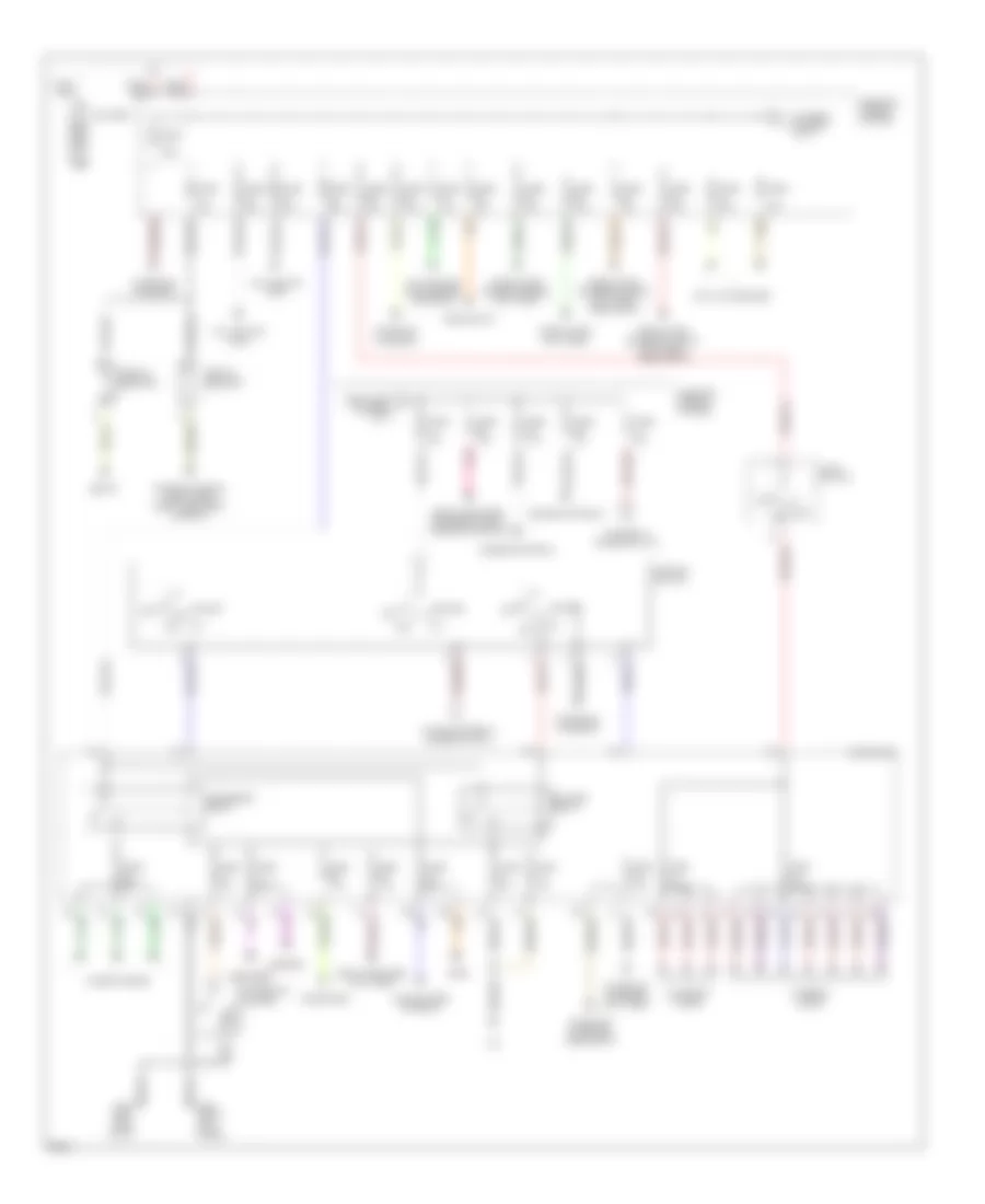
Power Distribution Wiring Diagram (1 of 2) for Infiniti I30 t 1997
List of elements for Power Distribution Wiring Diagram (1 of 2) for Infiniti I30 t 1997:
- 1st
- 2nd
- A/c
- A/c, cooling fans
- A/c, cooling fans, engine controls
- Acc
- Accessory relay
- Anti-lock brakes
- Audio, power antenna
- Battery
- Blower relay
- Body computer, anti-theft
- Body computer, exterior lights, engine controls
- Cigarette lighter
- Circuit breaker
- Defogger
- Door locks, anti-theft
- Door locks, cruise control, anti-theft
- Door locks, exterior lights, anti-theft, headlights
- Engine controls
- Exterior lights
- From fuse i a (diagram 1 of 1)
- Fuse 10a
- Fuse 15a
- Fuse 20a
- Fuse 7.5a
- Fuse a 140a
- Fuse and fusible link box
- Fuse b 65a
- Fuse block
- Fuse d 30a
- Fuse e 30a
- Fuse f 30a
- Fuse g 30a
- Fuse h 30a
- Fuse i 30a
- Fuse k 75a
- G202 (left side of i/p)
- G203 (right kick panel)
- Headlights
- Horn
- Ignition switch
- Interior lights
- Light switch
- Mirrors
- Off
- Pnk
- Power windows, door locks body computer, sunroof
- Seats
- Start
- Starting/ charging
- Starting/ charging, anti-theft
- Starting/ charging, headlights
- Telephone
- To fuse 11 (diagram 2 of 2)
- To fuse h (diagram 1 of 1)
- To ignition relay (diagram 2 of 2)
- Wiper/washer
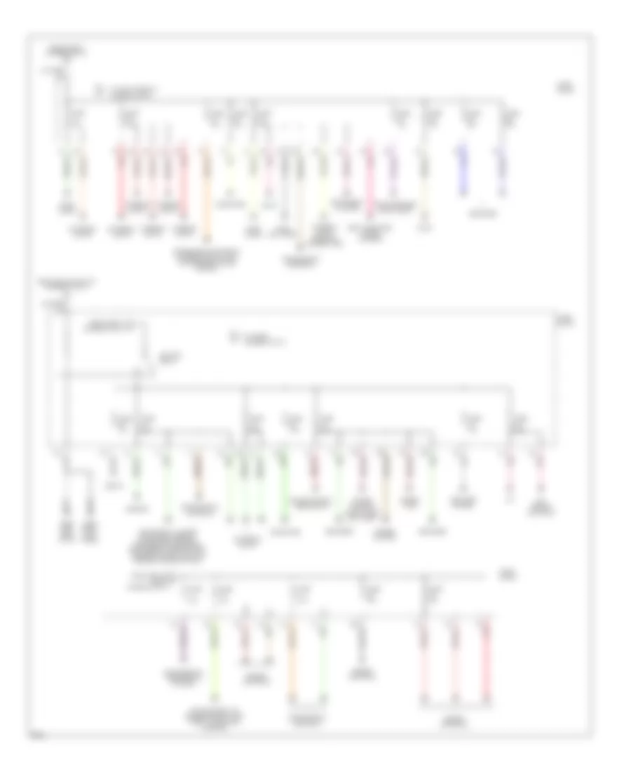
Power Distribution Wiring Diagram (2 of 2) for Infiniti I30 t 1997
List of elements for Power Distribution Wiring Diagram (2 of 2) for Infiniti I30 t 1997:
- 11g
- 11s pnk
- 12g
- 13g
- 14j pnk
- 3p red
- A/c
- A/c, engine controls
- Anti-lock brakes
- Audio
- Body computer, power antenna
- Cooling fans, a/c cruise control, anti- theft, startining/ charging
- Cruise control
- Cruise control, headlights
- Defogger
- Door locks
- Engine controls
- Exterior lights
- From fuse 11 d (diagram 2 of 2)
- From fuse k (diagram 1 of 2)
- From ignition e relay (diagram 2 of 2)
- From ignition switch (diagram 1 of 2)
- Fuse 10a
- Fuse 15a
- Fuse 20a
- Fuse 7.5a
- Fuse block
- G202 (left side of i/p)
- G203 (right kick panel)
- Horn, anti-theft
- Ignition relay
- Instrument cluster
- Interior lights
- Interior lights, homelink transmitter
- Mirrors
- Pnk
- Power tops
- Power windows, door locks, anti-theft
- Red
- Seats
- Telephone
- To fuse 1 (diagram 2 of 2)
- To ignition relay (diagram 2 of 2)
- Transmission controls
- Transmission controls, exterior lights, anti- lock brakes, cruise control
- Trunk release, door locks
POWER DOOR LOCKS
Power Door Lock Wiring Diagram for Infiniti I30 t 1997
List of elements for Power Door Lock Wiring Diagram for Infiniti I30 t 1997:
- stroke & normal
- stroke & normal unlock-between full
- (left "b" pillar) g308
- (right "b" pillar) g305
- 10g
- Ant
- Bat
- Body control module (below front of center console)
- Circuit breaker 2 (left kick panel)
- Data line a
- Data line b
- Door lock
- Door sw
- Door sw (as)
- Door sw (dr)
- Door unlock
- Dr unlock
- Driver door control unit (in driver's door)
- Driver side front door key cylinder switch
- Driver side front door lock actuator
- Driver side front door switch
- Exterior lights system
- Fuse 15a
- Fuse 7.5a
- Fuse block
- G202 (left side of i/p)
- G203 (right kick panel)
- G407 (center rear of trunk)
- Gnd
- Ground
- Hazard
- Hot at all times
- Hot in on or start
- Ign
- Key
- Key sw
- Left rear door control unit (in left rear door)
- Left rear door lock actuator
- Left rear door switch
- Lock sw
- Lock-between full
- Multi remote control relay 1 (center rear of trunk)
- Multi remote control unit (right rear of trunk)
- Nca
- Passenger door control unit (in right front door)
- Passenger side front door key cylinder switch
- Passenger side front door lock actuator
- Passenger side front door switch
- Pnk
- Right rear door control unit (in right rear door)
- Right rear door lock actuator
- Right rear door switch
- Switch
- T/lid sv
- Trunk lid opener actuator
- Trunk lid opener switch
- Unlock sens
- Unlock sw
- Window antenna
POWER MIRRORS
Auto Anti-dazzling Inside Mirror for Infiniti I30 t 1997
List of elements for Auto Anti-dazzling Inside Mirror for Infiniti I30 t 1997:
- 1st
- 2nd
- Fuse 10a
- Fuse 7.5a
- Fuse block (behind left side of dash)
- G202 (left side of i/p)
- G203 (right kick panel)
- Hot at all times
- Hot in on or start
- Illumination control unit (under center of dash)
- Inside mirror
- Lighting switch
- Off
Power Mirror Wiring Diagram for Infiniti I30 t 1997
List of elements for Power Mirror Wiring Diagram for Infiniti I30 t 1997:
- Change over switch
- D34
- D35
- Defogger system (door mirror defogger relay)
- Door mirror remote control switch
- Driver's side door mirror actuator
- Fuse 7 10a
- Fuse block (left side of dash)
- G202 (left side of i/p)
- G203 (right kick panel)
- Hot in acc or on
- Left/right motor
- Mirror heater
- Mirror switch
- Passenger's side door mirror actuator
- Up/down motor
POWER SEATS
Heated Seats Wiring Diagram for Infiniti I30 t 1997
List of elements for Heated Seats Wiring Diagram for Infiniti I30 t 1997:
- 12q
- Fuse 10a
- Fuse block (behind left side of dash)
- G305 (right "b" pillar)
- G308 (left "b" pillar)
- High
- Hot in on or start
- Indicator
- Indicator lamps
- Lamps
- Left heated seat
- Left heated seat switch
- Low
- Off
- Right heated seat
- Right heated seat switch
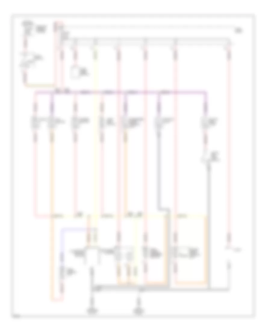
Power Seats Wiring Diagram for Infiniti I30 t 1997
List of elements for Power Seats Wiring Diagram for Infiniti I30 t 1997:
- Circuit breaker 1 (behind left side of dash)
- Driver's side power seat
- Ft lifter motor
- G305 (right "b" pillar)
- G308 (left "b" pillar)
- Hot at all times
- Passenger's side power seat
- Reclining motor
- Rr lifter motor
- Slide motor
POWER TOP/SUNROOF
Power Top/Sunroof Wiring Diagrams for Infiniti I30 t 1997
List of elements for Power Top/Sunroof Wiring Diagrams for Infiniti I30 t 1997:
- Circuit breaker 1 (left side of dash)
- Close
- Down
- Fuse 7.5a
- Fuse block
- G200 (left kick panel)
- G203 (right kick panel)
- Hot at all times
- Hot in on or start
- Nca
- Open
- Red
- Slide switch
- Sun roof relay (left side of dash)
- Sunroof motor assembly (center front of roof)
- Sunroof switch
- Tilt switch
POWER WINDOWS
Power Window Wiring Diagram for Infiniti I30 t 1997
List of elements for Power Window Wiring Diagram for Infiniti I30 t 1997:
- (left "b" pillar) g308
- (left side of i/p) g202
- (right "b" pillar) g305
- Ant
- Bat
- Body control module (bcm) (below center of dash)
- Circuit breaker 2 (left kick panel)
- Data line a
- Data line b
- Door lock
- Door unlock
- Driver door control unit
- Front power window regulator (driver side)
- Front power window regulator (passenger side)
- Fuse 7.5a
- Fuse block (behind left side of dash)
- G10
- G203 (right kick panel)
- G305 (right "b" pillar)
- G308 (left "b" pillar)
- G404 (left rear side of trunk)
- G405 (right rear side of trunk)
- Gnd
- Hot at all times
- Hot at all times
- Hot in on or start
- Ign
- Illumination
- Interior lights system
- Left front door key cylinder switch
- Left front door lock actuator
- Left front step lamp
- Left rear door control unit
- Left rear door lock actuator
- Left rear power window regulator (driver side)
- Lock sw
- Multi-remote control unit (right side of luggage compt)
- Nca
- Passenger door control unit
- Pnk
- Right front door key cylinder switch
- Right front door lock actuator
- Right front step lamp
- Right rear door control unit
- Right rear door lock actuator
- Right rear power window regulator (passenger side)
- Step lamp
- T/lid s/v
- Trunk lid opener actuator
- Unlock sens
- Unlock sw
- Window antenna
- Window down
- Window up
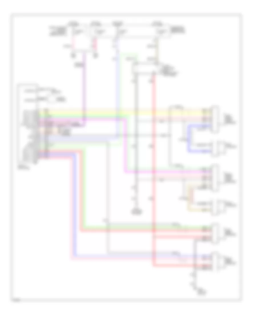
RADIO
Radio Wiring Diagrams for Infiniti I30 t 1997
List of elements for Radio Wiring Diagrams for Infiniti I30 t 1997:
- (or pnk)
- 15g
- 1996,
- 1998,
- Acc
- Antenna ctrl
- Antenna in
- Antenna in
- Audio amplifier relay (behind right kick panel)
- Battery
- Fr lh (+) amp
- Fr lh (-) amp
- Fr rh (+) amp
- Fr rh (-) amp
- Fuse & fusible link box (left side of engine compt)
- Fuse 21 10a
- Fuse 22 15a
- Fuse 40 7.5a
- Fuse 62 15a
- Fuse block (behind left side of dash)
- G202 (left side of dash)
- G308 (left "b" pillar)
- Ground
- Hot at all times
- Hot in on or acc
- Illum
- Interior lights system
- Left front door speaker
- Left rear speaker
- Left tweeter
- Nca
- On signal
- Pnk
- Power antenna
- Radio & cd player
- Red
- Right front door speaker
- Right rear speaker
- Right tweeter
- Rod antenna
- Rr lh (+) amp
- Rr lh (-) amp
- Rr rh (+) amp
- Rr rh (-) amp
- Window antenna
SHIFT INTERLOCKS
Shift Interlock Wiring Diagram for Infiniti I30 t 1997
List of elements for Shift Interlock Wiring Diagram for Infiniti I30 t 1997:
- A/t device (below front of center console)
- Ascd cancel switch (brake pedal support)
- Cruise control system
- Diode
- Fuse 7.5a
- Fuse block
- G202 (left side of i/p)
- G203 (right kick panel)
- Hot in on or start
- Park position switch
- Shift lock solenoid
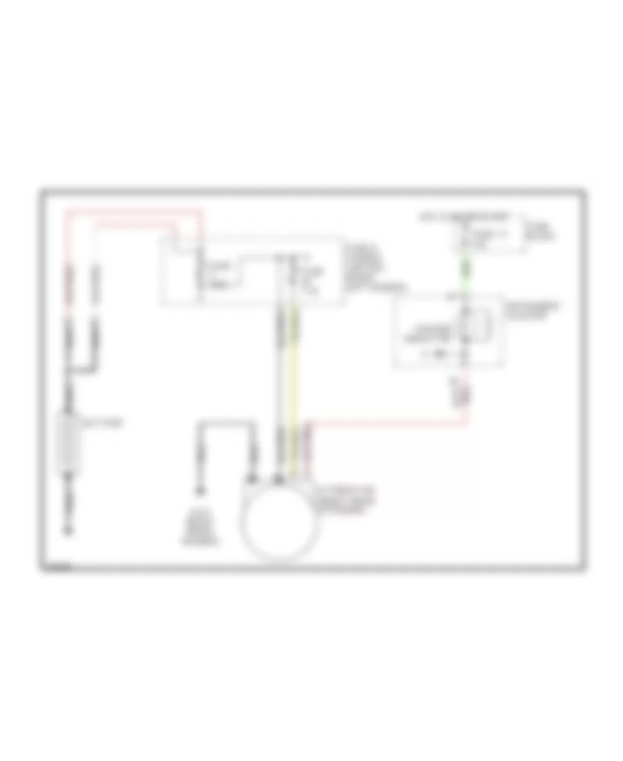
STARTING/CHARGING
Charging Wiring Diagram for Infiniti I30 t 1997
List of elements for Charging Wiring Diagram for Infiniti I30 t 1997:
- (right front of engine)
- Alternator
- Battery
- Charge indicator
- Fuse & fusible link box (front left fender)
- Fuse 13 10a
- Fuse 7.5a
- Fuse a 140a
- Fuse block
- G101 (right front fender)
- Hot in on or start
- Instrument cluster
- Nca
Starting Wiring Diagram, A/T for Infiniti I30 t 1997
List of elements for Starting Wiring Diagram, A/T for Infiniti I30 t 1997:
- (below front of center console)
- 16l
- Acc
- Battery
- Body control module
- Cruise control system
- Fuse & fusible link box
- Fuse 17 10a
- Fuse block
- Fusible link h 30a
- G120 (right side of engine)
- Ignition switch
- Inhibitor relay (in relay box 1)
- Inhibitor switch (on transmission)
- Nca
- Off
- Red
- Start
- Starter motor
- Theft warning relay 1 (in relay box 2)
Starting Wiring Diagram, M/T for Infiniti I30 t 1997
List of elements for Starting Wiring Diagram, M/T for Infiniti I30 t 1997:
- (below front of center console)
- 16l
- Acc
- Battery
- Body control module
- Clutch inter- lock relay (in relay box 1)
- Clutch interlock switch (left side of i/p)
- Fuse & fusible link box
- Fuse 17 10a
- Fuse 33 7.5a
- Fuse bock
- Fusible link h 30a
- G202 (left side of i/p)
- G203 (right kick panel)
- Ignition switch
- Nca
- Off
- Red
- Start
- Starter motor
- Theft warning relay 1 (in relay box 2)
SUPPLEMENTAL RESTRAINTS
Supplemental Restraint Wiring Diagram for Infiniti I30 t 1997
List of elements for Supplemental Restraint Wiring Diagram for Infiniti I30 t 1997:
- (in left front door jamb)
- 15j
- Air bag diagnosis sensor unit (center of i/p)
- Air bag ind.
- Data link connector (left side of i/p)
- Door sw
- Fuse 1 10a
- Fuse 13 10a
- Fuse block
- G200 (left kick panel)
- G202 (left side of dash)
- Gnd
- Hot in on or start
- Ign
- Instrument cluster
- Led
- Left air bag module
- Left front door switch
- Nca
- Pnk
- Red
- Right air bag module
- Spiral cable
- Sq as1 +
- Sq as1 -
- Sq dr +
- Sq dr -
- Sss rx
- Sss tx
TRANSMISSION
A/T Wiring Diagram for Infiniti I30 t 1997
List of elements for A/T Wiring Diagram for Infiniti I30 t 1997:
- (below left side of dash) (for consult)
- 1-sw
- 13g
- 17j
- 18j
- 19j
- 2-sw
- A/t control
- A/t fluid temp sensor
- Ascd
- Ascd control unit (behind center of dash)
- Atck
- Automatic transaxle nca
- Avcc
- Brk sw
- Closed
- Clsd sw
- Combination meter
- Cruis sw
- D-sw
- Data clk
- Data in
- Data link connector (dlc)
- Data out
- Dropping resistor (left side of eng compt)
- Dt1
- Dt2
- Dt3
- Dt4
- Dt5
- Dts
- Engine control module (ecm) (behind center of dash)
- Engine coolant temperature sensor (top left side of engine)
- Fl temp
- Fuse 10a
- Fuse 15a
- Fuse 7.5a
- Fuse block (left side of dash)
- G112 (left side of engine)
- G202 (left side of dash)
- G203 (right kick panel)
- Grd
- Grd-a
- Hot at all times
- Hot in on or start
- Idle
- Inhibitor switch (top of transaxle)
- J/c
- Line press. sol valve
- Lp sol
- Mem bu
- N-sw
- Nca
- Neut
- O/d ctrl
- O/d off ind
- Obd2
- Od off
- Over- run clutch sol
- Overdrive control switch
- Ovr sol
- Pnk
- Pwr sen
- R-sw
- Red
- Revolution sensor (on rear of transaxle)
- Sens grd
- Shift sol valve a
- Shift sol valve b
- Sp sens
- Speedometer
- Ssa
- Ssb
- Stop lamp switch (above brake pedal)
- Tacho
- Tcc sol
- Tcc sol valve
- Throttle position sensor (on throttle body)
- Throttle position switch (on throttle body)
- Ts in
- Tvo
- Tvoo
- Unit (behind center of dash)
- V ign
- Vehicle speed sensor (on transaxle)
- Vsp
- Vsp-1
- W/o sw
- Wide open
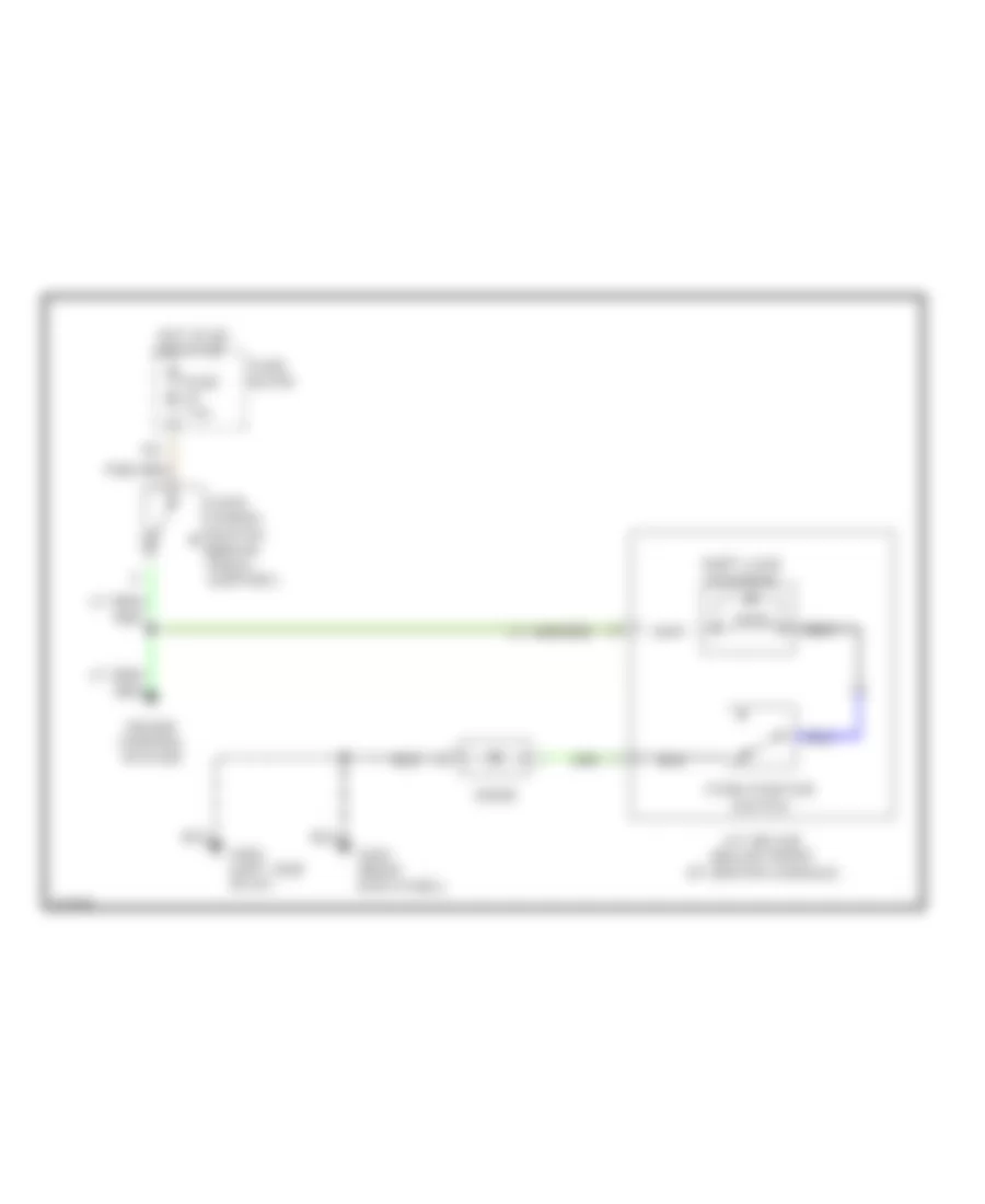
TRUNK, TAILGATE, FUEL DOOR
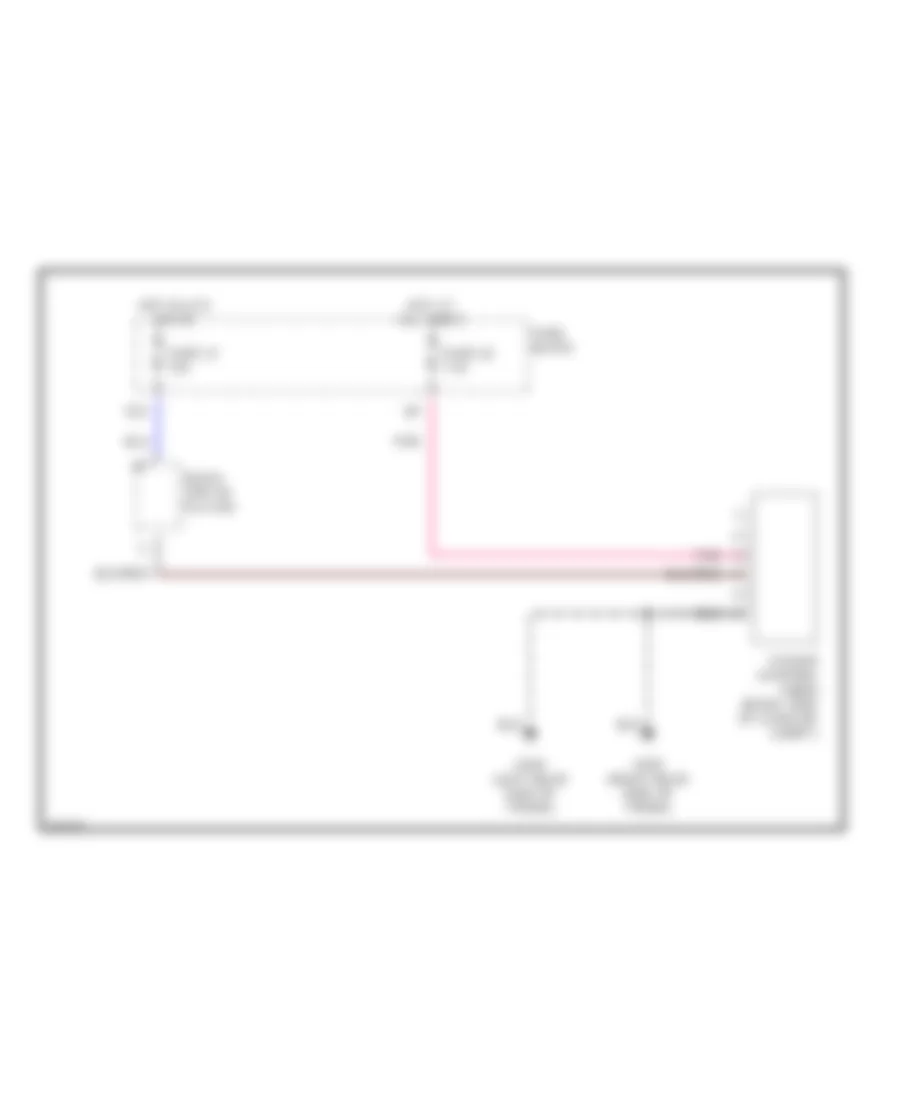
Trunk & Fuel Door Release Wiring Diagram for Infiniti I30 t 1997
List of elements for Trunk & Fuel Door Release Wiring Diagram for Infiniti I30 t 1997:
- Fuel lid opener actuator
- Fuel lid opener switch
- Fuse 15a
- Fuse block
- G202 (left side of dash)
- G203 (right kick panel)
- Hot at all times
- Trunk lid opener actuator
- Trunk lid opener switch
WARNING SYSTEMS
Warning System Wiring Diagrams for Infiniti I30 t 1997
List of elements for Warning System Wiring Diagrams for Infiniti I30 t 1997:
- 10g
- Acc
- Belt in
- Body control module (bcm) (behind center console)
- Buzzer
- Door sw
- Driver's seat belt buckle switch
- Driver's side door switch
- Fuse 10a
- Fuse 7.5a
- Fuse block
- G305 (right "b" pillar)
- G308 (left "b" pillar)
- Head
- Hot at all times
- Hot in acc or on
- Hot in on or start
- Ign
- Instrument cluster
- Key sw
- Key switch
- Light 1st
- Lighting switch
- Off
- Park
- Seat belt ind
- Warning buzzer (below left side of dash)
WIPER/WASHER
Wiper/Washer Wiring Diagram for Infiniti I30 t 1997
List of elements for Wiper/Washer Wiring Diagram for Infiniti I30 t 1997:
- 15l
- Body control module (below front of center console)
- Front wiper motor (right side of safety wall)
- Front wiper relay (relay box 2, right front fender)
- Fuse 20a
- Fuse block
- G100 (left front fender)
- G101 (right front fender)
- G202 (left side of i/p)
- G203 (right kick panel)
- Hot in acc or on
- Int
- Inter- mittent
- Nca
- Off
- Wash
- Washer motor (right front of engine compartment)
- Wiper switch

 Čeština
 Dansk
Dansk Deutsch
 Ελληνικά
 English
 English
 Español
 Suomi
Suomi Français
 Français
 עברית
עברית Hrvatski
 Magyar
 Italiano
 日本語
日本語 한국어
한국어 Nederlands
 Polski
 Português
 Português
 Română
 Русский
 Slovenčina
 Svenska
 Türkçe
 中文 (中国)