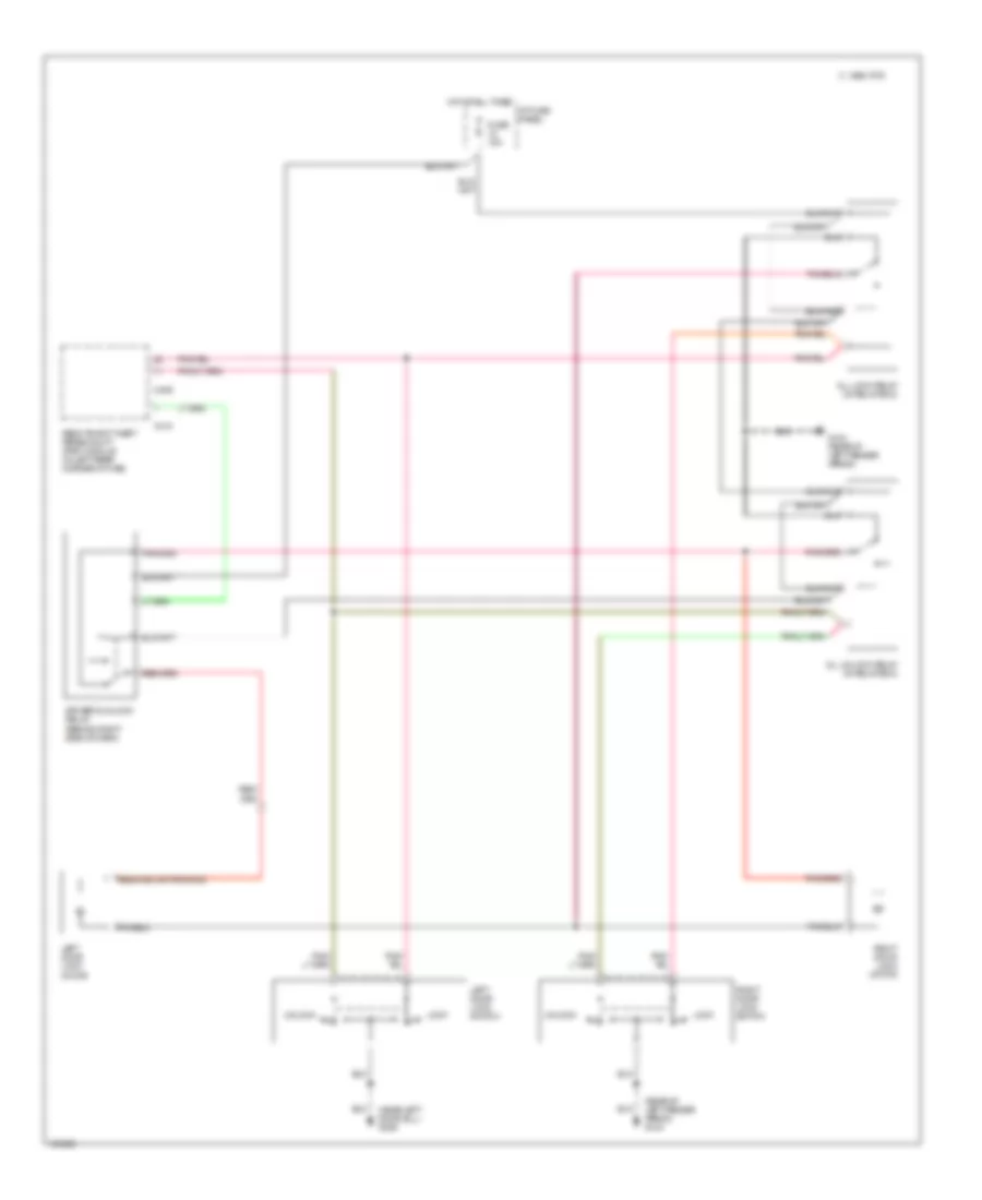
AIR CONDITIONING
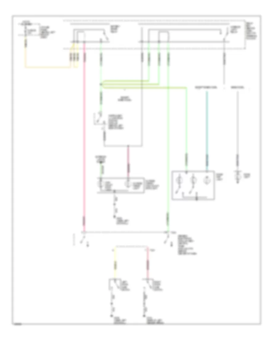
Heater Wiring Diagram for Mazda BSE 1999 3000
 https://portal-diagnostov.com/license.html
Automotive Electricians Portal FZCO
Automotive Electricians Portal FZCO
https://portal-diagnostov.com/license.html
https://portal-diagnostov.com/license.html
Automotive Electricians Portal FZCO
Automotive Electricians Portal FZCO
List of elements for Heater Wiring Diagram for Mazda BSE 1999 3000:
- (1999) (top center of left fender apron) g102
- (2000) (left kick panel) g200
- Blower motor (right rear of engine compartment, on firewall)
- Blower motor relay (in engine compartment fuse/relay box)
- Blower motor resistor assembly (right rear of engine compartment, near blower motor)
- Defrost
- Engine compartment fuse/relay box (left rear of engine compartment)
- Floor
- Flr/def
- Fuse 40a
- Fuse 7.5a
- G-232
- G-233
- G-234
- Heater control assembly
- Hot at all times
- Hot in run
- I/p fuse panel (behind left side of dash)
- Illumi- nation
- Interior lights system
- Med hi
- Med lo
- Off
- Panel
- Panel/ floor
- Thermal limiter
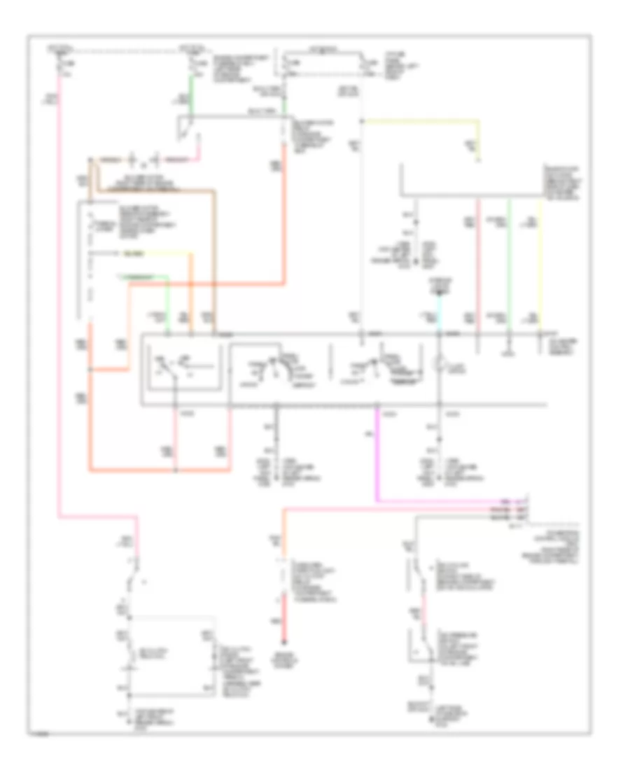
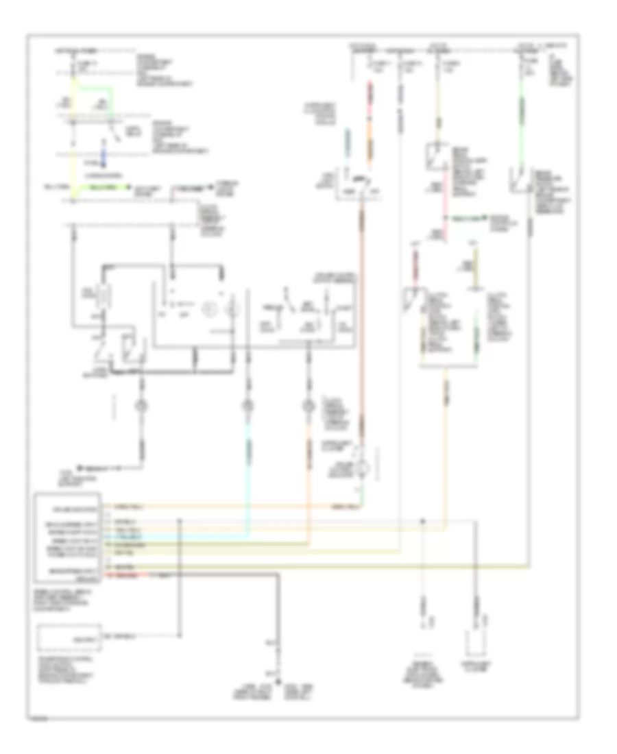
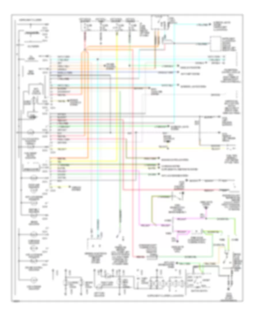
Manual A/C Wiring Diagram for Mazda BSE 1999 3000
List of elements for Manual A/C Wiring Diagram for Mazda BSE 1999 3000:
- (1999) (top center of left fender apron) g102
- (2000) (left kick panel) g200
- (left side of radiator support) g108
- (top center of left front fender apron) g102
- A/c
- A/c clutch diode (left front of engine compartment, taped in harness, near a/c clutch field coil)
- A/c clutch field coil
- A/c cycling switch (in right side of engine compartment, on a/c accumulator)
- A/c pressure switch (in left front of engine compartment, on a/c line)
- A/c-heater control assembly
- B-111
- Blend door actuator (behind right side of dash, on heater- a/c housing)
- Blower motor (right rear of engine compartment, on firewall)
- Blower motor relay (in engine compartment fuse/relay box)
- Blower motor resistor assembly (right rear of engine compartment, near blower motor)
- Defrost
- Engine compartment fuse/relay box (left rear of engine compartment)
- Engine controls system
- Floor
- Floor flr/def
- Flr/def
- Fuse 10a
- Fuse 40a
- Fuse 7.5a
- G-231
- G-232
- G-233
- G-234
- Hot at all times
- Hot in run
- I/p fuse panel (behind left side of dash)
- Illumi- nation
- Interior lights system
- Max a/c
- Med hi
- Med lo
- Off
- Panel
- Panel/ floor
- Powertrain control module (pcm) (right rear of engine compartment, through firewall)
- Red
- Thermal limiter
- Wide open throttle (wot) a/c cut off relay (in engine compartment fuse/relay box)
ANTI-LOCK BRAKES
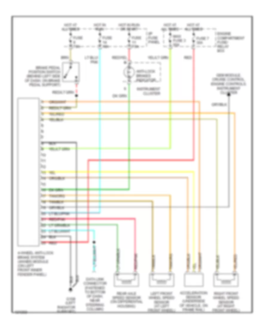
All-Wheel ABS Wiring Diagram for Mazda BSE 1999 3000
List of elements for All-Wheel ABS Wiring Diagram for Mazda BSE 1999 3000:
- 4-wheel anti-lock brake system (4wabs) module (on left front inner fender panel)
- Acceleration sensor (underside of vehicle, on frame rail)
- Anti-lock brakes indicator
- Brake pedal position switch (behind left side of dash, on brake pedal support)
- Data link connector (fastened to bottom of dash, near steering column)
- Engine compartment fuse/ relay box
- Fuse 10a
- Fuse 7 30a
- Fuse 7.5a
- G108 (left radiator support)
- Gem module, cruise control, engine controls, instrument cluster
- Hot at all times
- Hot in run
- Hot in run or start
- I/p fuse panel
- Instrument cluster
- Left front wheel speed sensor (at left front wheel)
- Maxi fuse 3 50a
- Rear axle speed sensor (on differential housing)
- Red
- Red/pnk
- Right front wheel speed sensor (at right front wheel)
Rear Wheel ABS Wiring Diagram for Mazda BSE 1999 3000
List of elements for Rear Wheel ABS Wiring Diagram for Mazda BSE 1999 3000:
- Abs ind
- Acc
- Brake fluid level sensor (on brake fluid reservoir)
- Brake ind
- Brake pedal position (bpp) switch (behind left side of dash, on brake pedal support)
- C216
- Drl module
- Engine compartment fuse/relay box (left rear of engine compt)
- Fuse 11 7.5a
- Fuse 14 20a
- Fuse 30 10a
- Fuse 9 7.5a
- G104 (rear of left fender apron)
- G108 (left radiator support)
- Generic electronic module (gem) (behind center of dash)
- Hot at all times
- Hot in run
- Hot in run or start
- I/p fuse panel (left side of dash)
- Ignition switch
- Instrument cluster
- Isolation solenoid
- Lock
- Nca
- Off
- Park brake switch (on park brake assembly)
- Rabs data link connector (left rear of engine compt)
- Rabs diode
- Rabs test connector (behind right side of dash)
- Rabs/ low fluid resistor
- Rear anti-lock brake system (rabs) module (behind lower center of dash)
- Rear anti-lock brake system (rabs) proportioning valve switch assembly (below left side of vehicle, on inside of left frame rail)
- Rear axle speed sensor (on differential housing)
- Red
- Red/pnk
- Run
- Start
- Valve reset switch
ANTI-THEFT
Forced Entry Wiring Diagram for Mazda BSE 1999 3000
List of elements for Forced Entry Wiring Diagram for Mazda BSE 1999 3000:
- (rear of right front fender) g105
- 1996 vftc c
- Alarm
- All lock relay
- All unlock relay
- Anti- theft hood switch (on right front inner fender panel)
- C214
- C222
- C409
- C410
- Data link connector (fastened to bottom of dash, near steering column)
- Driver's unlock relay (behind right side of dash)
- Engine compartment fuse/relay box (left rear of engine compt)
- Exterior lights system
- Fuse 18 15a
- Fuse 20 7.5a
- Fuse 9 20a
- G104 (rear of left front fender)
- G108 (left radiator support)
- G309 (near left door sill)
- Generic electric module (gem) (behind center of dash)
- Generic electronic module
- Horn system
- Hot at all times
- Hot in run or start
- I/p fuse panel (behind left side of dash)
- Instrument cluster
- Left door disarm switch
- Left door lock motor
- Left door lock switch
- Lock
- Not used
- Relay box (behind dash, right of steering column)
- Remote anti-theft personality (rap) module (in left rear corner of cab)
- Right door disarm switch
- Right door lock motor
- Right door lock switch
- Un- lock
- Unlock
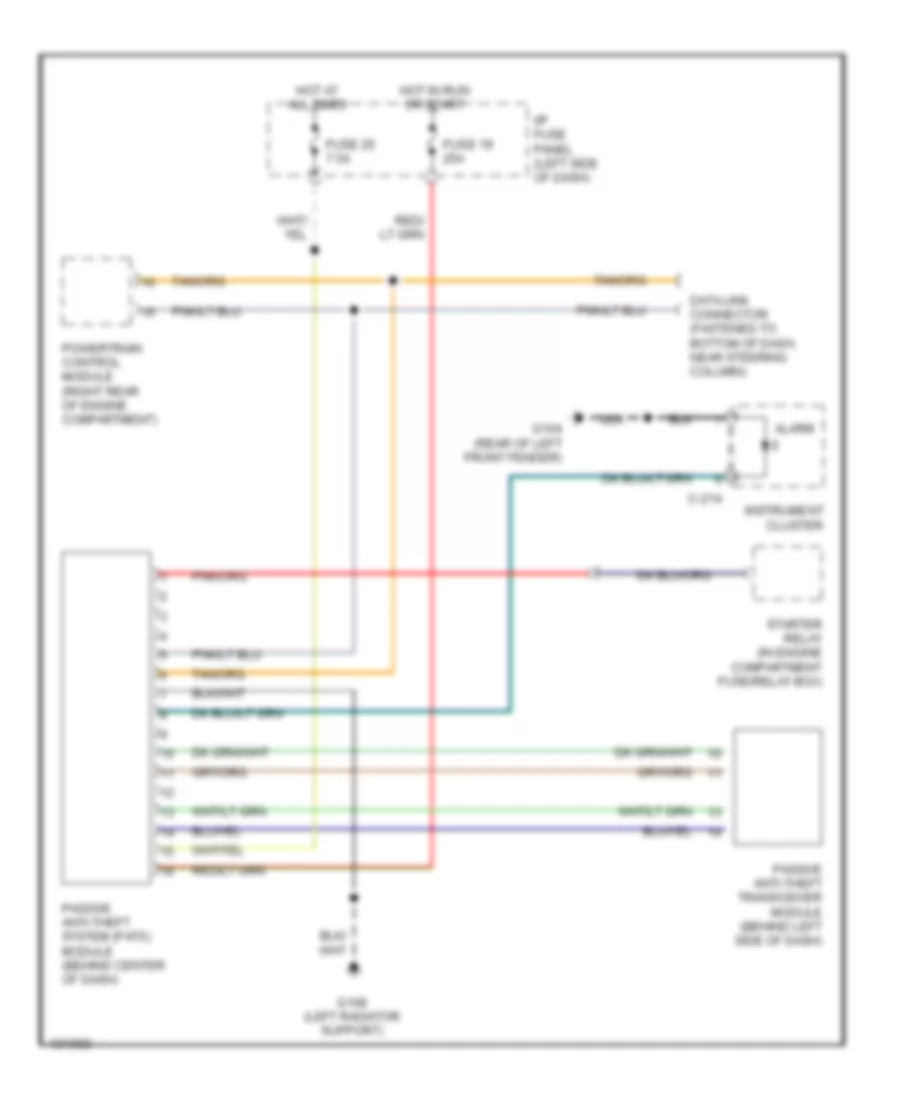
Immobilizer Wiring Diagram, PATS for Mazda BSE 1999 3000
List of elements for Immobilizer Wiring Diagram, PATS for Mazda BSE 1999 3000:
- Alarm
- C-214
- Data link connector (fastened to bottom of dash, near steering column)
- Fuse 19 25a
- Fuse 25 7.5a
- G104 (rear of left front fender)
- G108 (left radiator support)
- Hot at all times
- Hot in run or start
- I/p fuse panel (left side of dash)
- Instrument cluster
- Passive anti-theft system (pats) module (behind center of dash)
- Passive anti-theft transceiver module (behind left side of dash)
- Powertrain control module (right rear of engine compartment)
- Starter relay (in engine compartment fuse/relay box)
BODY COMPUTER
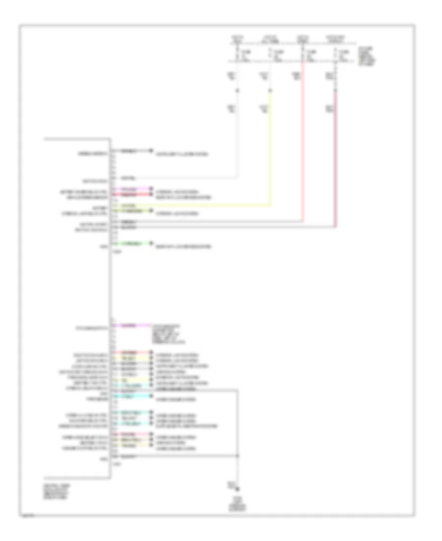
Central Timer Module Wiring Diagram for Mazda BSE 1999 3000
List of elements for Central Timer Module Wiring Diagram for Mazda BSE 1999 3000:
- Airbag diagnostic monitor
- Battery
- Battery saver relay ctrl
- C221
- C224
- Central timer module (ctm) (behind right side of dash)
- Ctm diagnostic connector (below left of dash, left of steering column)
- Ctm diagnostic in
- Door ajar ind ctrl
- Exterior lights system
- Fuse 7.5a
- G108 (left radiator support)
- Gnd
- Hot at all times
- Hot in acc or run
- Hot in run
- Hot in start
- I/p fuse panel (behind left side of dash)
- Ignition (acc/run)
- Ignition (run)
- Ignition (start)
- Ignition key warning sw in
- Instrument cluster system
- Interior lamp relay ctrl
- Interior lights system
- Interval delay/wash in
- Left door ajar in
- Park sense
- Park/headlamps on in
- Rear anti-lock brakes system
- Red/pnk
- Right door ajar in
- Run/park relay ctrl
- Seat belt ind ctrl
- Seat belt sw in
- Speedometer in
- Tan/red
- Vehicle speed sensor
- Warning system
- Washer pump relay ctrl
- Wiper hi-lo relay ctrl
- Wiper mode select sw in
- Wiper/washer system
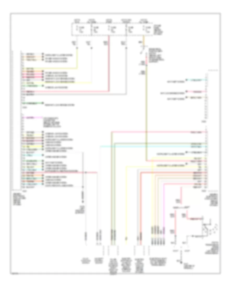
Generic Electronic Module Wiring Diagram for Mazda BSE 1999 3000
List of elements for Generic Electronic Module Wiring Diagram for Mazda BSE 1999 3000:
- 4x4 shift control switch
- Anti-lock brakes system
- Anti-theft system
- Brake pedal position (bpp) switch (behind left side of dash, on brake pedal support)
- C221
- C222
- C223
- C224
- Computer data lines system
- Ctm diagnostic connector (below left side of dash, left of steering column)
- Digital transmission range sensor (left side of transmission)
- Electric shift control module (behind center of dash)
- Electric shift relay (in relay box, right side of steering column)
- Electronic shift motor assembly (on left rear of transmission)
- Fuse 7.5a
- G108 (left radiator support)
- G121 (center of firewall)
- Generic electronic module (gem) (behind center of dash)
- Hot at all times
- Hot in acc or run
- Hot in run
- Hot in start
- I/p fuse panel (behind left side of dash)
- Instrument cluster system
- Interior lights system
- Multi- function switch
- Nca
- Power window system
- Pulse vacuum hublock solenoid (right front of engine compt)
- Rear anti-lock brakes system
- Red/pnk
- Tan/red
- Tel
- W/ a/t
- W/ m/t
- Warning system
- Wiper/washer system
COMPUTER DATA LINES
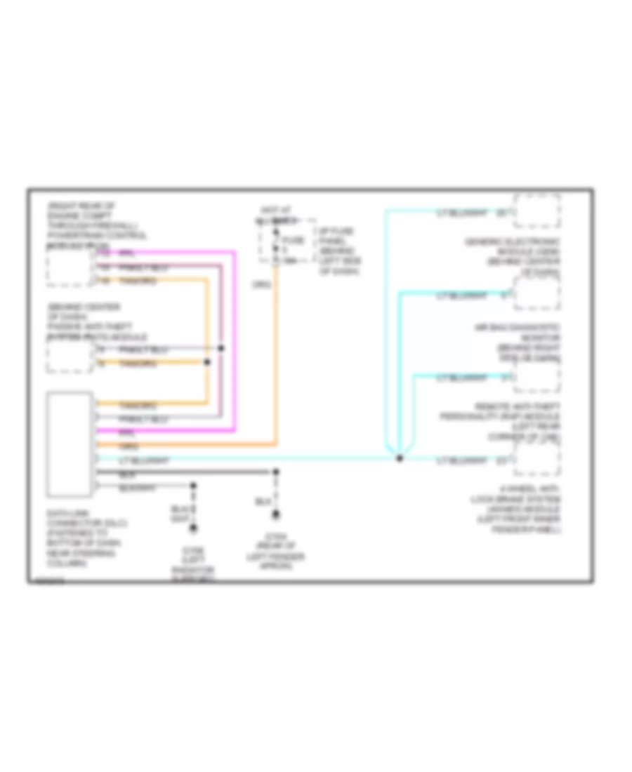
Computer Data Lines for Mazda BSE 1999 3000
List of elements for Computer Data Lines for Mazda BSE 1999 3000:
- (behind center of dash) passive anti-theft system (pats) module
- (right rear of engine compt through firewall) powertrain control module (pcm)
- 4 wheel anti- lock brake system (4wabs) module (left front inner fender panel)
- Air bag diagnostic monitor (behind right side of dash)
- Data link connector (dlc) (fastened to bottom of dash, near steering column)
- Fuse 10a
- G104 (rear of left fender apron)
- G108 (left radiator support)
- Generic electronic module (gem) (behind center of dash)
- Hot at all times
- I/p fuse panel (behind left side of dash)
- Remote anti-theft personality (rap) module (left rear corner of cab)
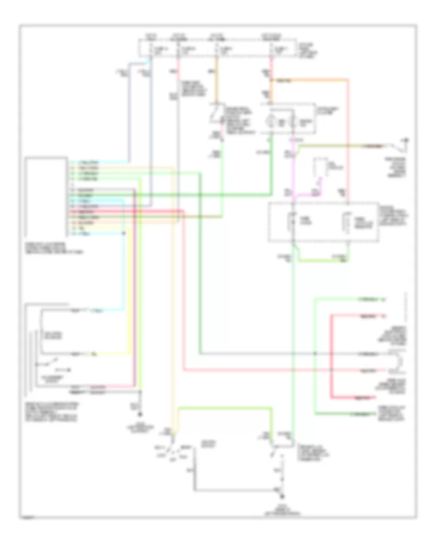
CRUISE CONTROL
Cruise Control Wiring Diagram for Mazda BSE 1999 3000
List of elements for Cruise Control Wiring Diagram for Mazda BSE 1999 3000:
- (1998)
- (1999)
- (left radiator support)
- 20a
- 7.5a
- A/t
- Accel
- Anti-theft system
- Brake on/off sw in
- Brake pedal position (bpp) switch (behind left side of dash, on brake pedal support)
- Brake press input
- Brake pressure switch (left rear of engine compartment, near fluid reservoir)
- C 1995 vftc
- C215
- C224
- Clock spring assembly (top of steering column)
- Clutch pedal position (cpp) switch (behind left side of dash, top of clutch pedal support)
- Clutch pedal position (cpp) switch jumper (left of steering column)
- Coast
- Cruise control indicator
- Cruise control switch assembly
- Cruise indicator
- Engine compartment fuse/relay box (left rear of engine compartment)
- Engine compartment fuse/relay box (left rear of enigne compartment)
- Engine controls system
- Fuse
- Fuse 10
- Fuse 10 15a
- Fuse 11
- Fuse 9
- G105 (rear of right front fender)
- G108
- G309 (near left door sill)
- Generic electronic module (gem) (behind center of dash)
- Ground
- Head
- Horn relay
- Horn switches
- Horns system
- Hot at all times
- Hot in run
- Hot in run or start
- I/p fuse panel (behind left side of dash)
- Instrument cluster
- Instrument illumination dimming module
- Interior lights system
- M/t
- Main light switch
- Nca
- Off
- Ohms
- Park
- Power (hot in run)
- Powertrain control module (pcm) (right rear of engine compartment, through firewall)
- Resume
- Set/
- Speed cont sw gnd
- Speed cont sw in
- Speed control servo/ amplifier assembly (right side of engine compartment)
- Vehicle speed input
- Vss input
ENGINE PERFORMANCE
3.0L
3.0L, Engine Performance Wiring Diagrams (1 of 4) for Mazda BSE 1999 3000
List of elements for 3.0L, Engine Performance Wiring Diagrams (1 of 4) for Mazda BSE 1999 3000:
- (fasten to bottom of dash, near steering column) data link connector (dlc)
- (left side of radiator support)
- Air conditioning system
- Anti-theft system
- C209
- C214
- C215
- Crankshaft position (ckp) sensor (on lower front of engine)
- Digital transmission range sensor (left side of transmission)
- Engine compartment fuse/relay box (left rear of engine compartment)
- Fuse 25a
- Fuse 7.5a
- G108
- G121 (center of firewall)
- Hot at all times
- Hot in run or start
- I/p fuse panel (behind left side of dash)
- Ignition coil (on rear of eng)
- Instrument cluster
- Malfunction indicator lamp (mil)
- Pcm power diode
- Pcm power fuse 8 30a
- Pcm power relay
- Powertrain control module (pcm) (right rear of engine compartment, through firewall)
- Radio noise capacitor (near ignition coil)
- Red
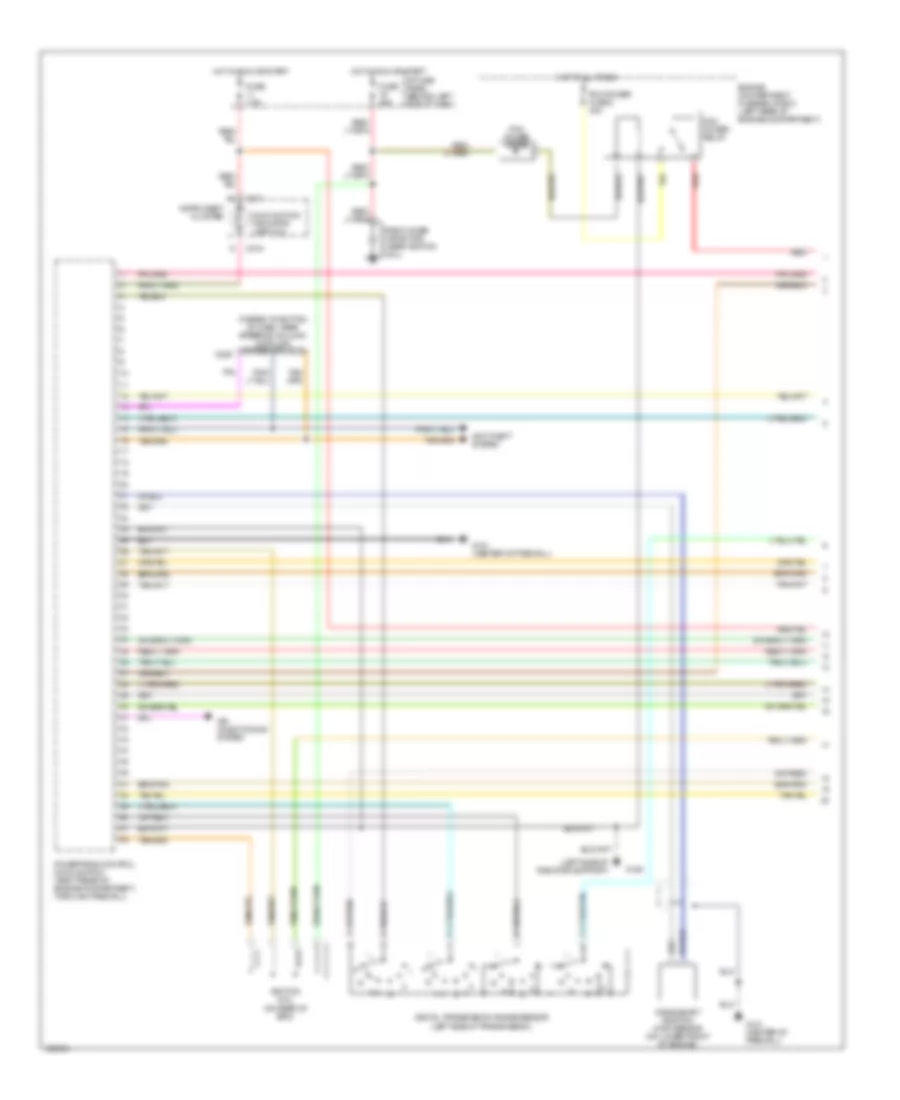
3.0L, Engine Performance Wiring Diagrams (2 of 4) for Mazda BSE 1999 3000
List of elements for 3.0L, Engine Performance Wiring Diagrams (2 of 4) for Mazda BSE 1999 3000:
- A/t
- Canister vent solenoid (behind left rear corner of vehicle)
- Clutch pedal position (cpp) switch (clutch pedal support)
- Clutch pedal position (cpp) switch jumper (behind dash, left of steering column)
- Differential pressure feedback egr sensor (left side of eng)
- Engine compartment fuse/relay box (left rear of engine compartment)
- Engine coolant temperature (ect) sensor (top right of eng, near thermostat housing)
- Evaporative emissions (evap) canister purge solenoid (left front of engine compt, near battery)
- Flex fuel vaporized sensor (at base of left "b" pillar)
- Fuel pump relay
- Fuse 13 15a
- Fuse 9 20a
- G121 (center of firewall)
- Hot at all times
- Intake air temperature (iat) sensor (on top left side of eng)
- M/t
- M/t
- Nca
- Red
- Throttle position (tp) sensor (on throttle body assembly)
- Wide open throttle a/c cutoff relay
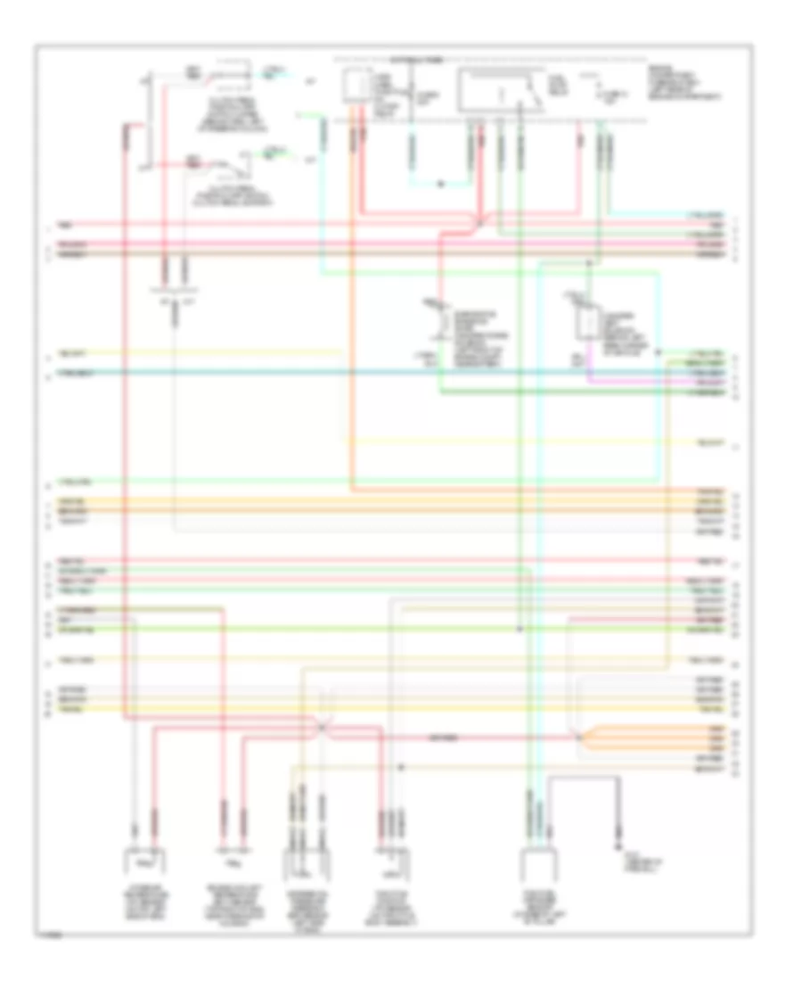
3.0L, Engine Performance Wiring Diagrams (3 of 4) for Mazda BSE 1999 3000
List of elements for 3.0L, Engine Performance Wiring Diagrams (3 of 4) for Mazda BSE 1999 3000:
- (behind lower center of dash) rear anti-lock brake system module
- (center of firewall)
- (left side of radiator support)
- (on differential housing) rear axle speed sensor
- (under right side of dash, near kick panel)
- 4-wheel anti- lock brake system module (on left front inner fender panel)
- 4wabs
- 4wd low indicator lamp
- Anti- slosh module
- Body computer
- C214
- C215
- Flex fuel only
- Fuel injectors
- Fuel pump/ fuel gauge sender
- Fuel reset switch indicator lamp
- Fuel tank assembly
- Fuel tank pressure sensor
- Fuse 10a
- G108
- G121
- Generic electronic module (gem)/ central timer module (ctm) (behind center of dash)
- Hot in run
- I/p fuse panel (behind left side of dash)
- Inertia fuel shut-off switch
- Instrument cluster
- Instrument cluster, cruise control
- Rabs
- Rabs test connector red/pnk
- Rear axle sensor (on differential) housing)
- Red
- Red/ pnk
- Red/pnk
- T-224
- Tach- ometer
- Tan
- Trans- mission control indicator lamp
- Transmission control switch (tcs)
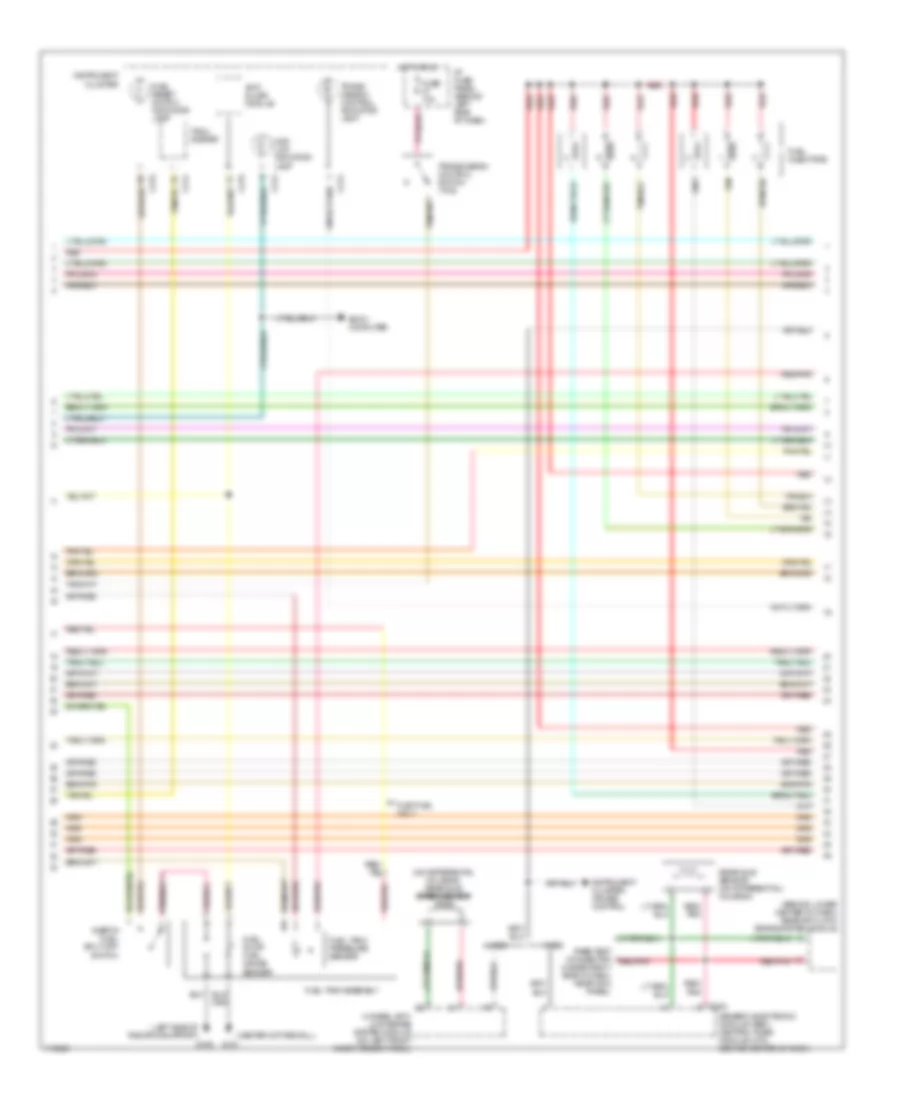
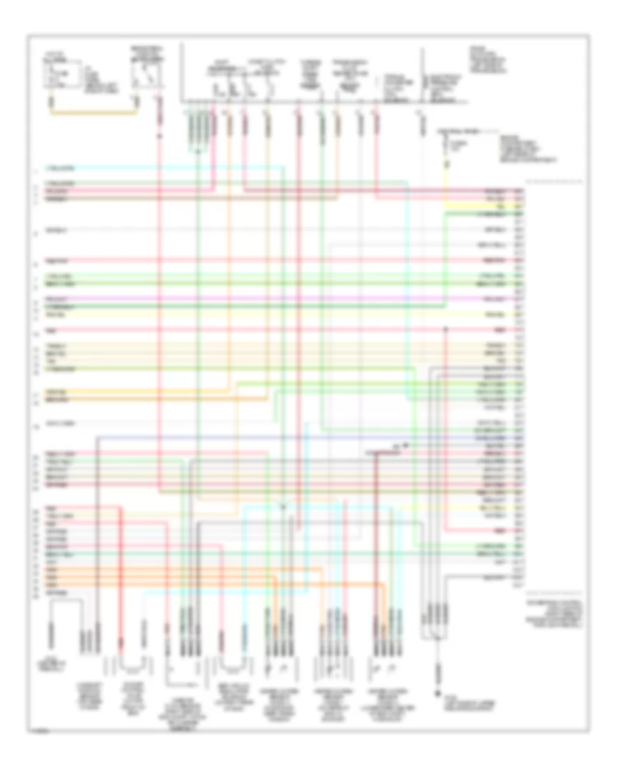
3.0L, Engine Performance Wiring Diagrams (4 of 4) for Mazda BSE 1999 3000
List of elements for 3.0L, Engine Performance Wiring Diagrams (4 of 4) for Mazda BSE 1999 3000:
- 4r44e automatic transmission (left side of transmission)
- Air conditioning
- Brake pedal position switch (bpp)
- Camshaft position sensor (top rear of eng)
- Coast clutch (css) solenoid
- Egr vacuum regulator solenoid (on right rear of eng)
- Electronic pressure control (epc) solenoid
- Engine compartment fuse/relay box (left rear of engine compartment)
- Fuse 6 10a
- Fuse 7.5a
- G108 (left side of upper radiator support)
- G121 (center of firewall)
- Heated oxygen sensor (ho2s) 1 (on rear of eng, in exhaust)
- Heated oxygen sensor (ho2s) 2 (lower rear center of eng compt, in exhaust)
- Heated oxygen sensor (ho2s) 3 (in exhaust, near trans- mission)
- Hot at all times
- I/p fuse panel (behind left side of dash)
- Idle air control valve (on top front of eng)
- Mass air flow sensor (right side of eng compt, within air cleaner assembly)
- Nca
- Powertrain control module (pcm) (right rear of engine compartment, through firewall)
- Red
- Red/pnk
- Shift solenoids
- Tan
- Torque converter clutch (tcc) solenoid
- Transmission fluid temperature (tft) sensor
- Turbine shaft speed (tss) sensor
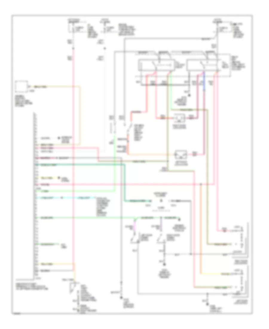
EXTERIOR LIGHTS
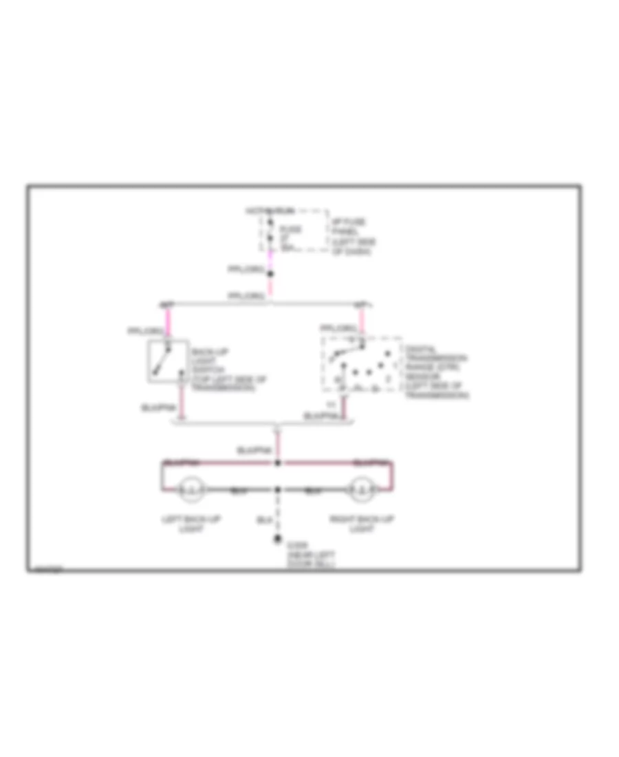
Backup Lamps Wiring Diagram for Mazda BSE 1999 3000
List of elements for Backup Lamps Wiring Diagram for Mazda BSE 1999 3000:
- A/t
- Back-up light switch (top left side of transmission)
- Digital transmission range (dtr) sensor (left side of transmission)
- Fuse 15a
- G309 (near left door sill)
- Hot in run
- I/p fuse panel (left side of dash)
- Left back-up light
- M/t
- Right back-up light
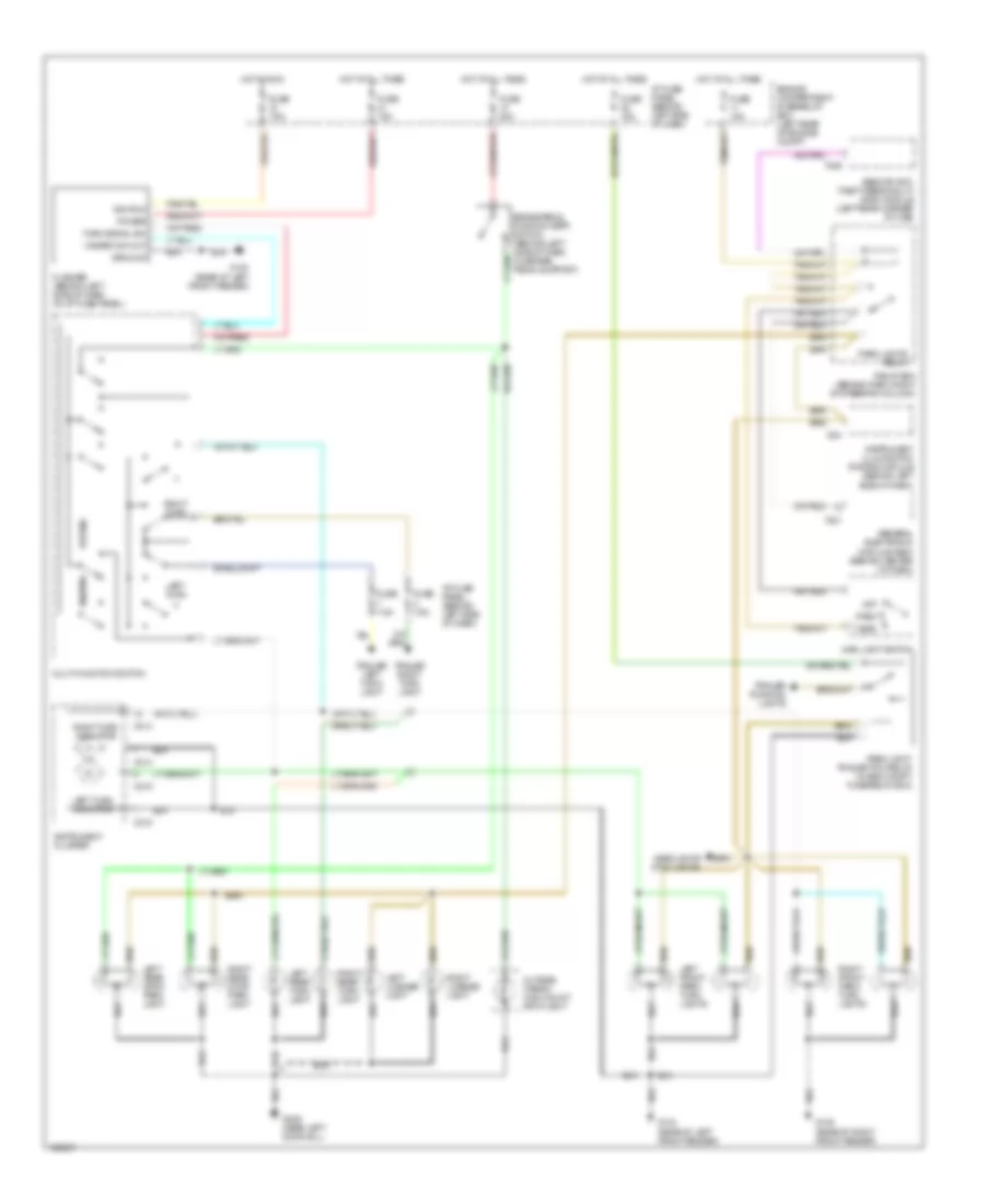
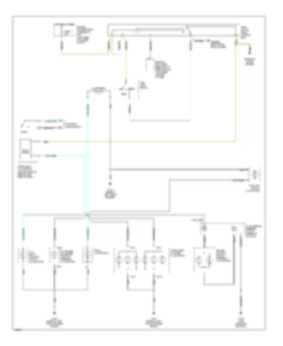
Exterior Lamps Wiring Diagram for Mazda BSE 1999 3000
List of elements for Exterior Lamps Wiring Diagram for Mazda BSE 1999 3000:
- Brake pedal position (bpp) switch (behind left side of dash, on brake pedal support)
- C214
- C215
- Engine compartment fuse/relay box (left rear of enigne compt)
- Flasher (behind left side of dash, on i/p fuse panel)
- Fuse 15a
- Fuse 20a
- Fuse 7.5a
- G104 (rear of left front fender)
- G105 (rear of right front fender)
- G309 (near left door sill)
- General electronic module (gem) (behind center of dash)
- Ground
- Hazard
- Hazard sw out
- Head
- Headlights (fog lights)
- Hot at all times
- Hot in run
- I/p fuse panel (behind left side of dash)
- I204
- Ignition
- Instrument cluster
- Instrument illumination dimming module (behind left side of dash)
- Left front park/ turn lights
- Left license light
- Left rear stop/ park light
- Left rear turn light
- Left turn
- Left turn indicator
- Main light switch
- Multi-function switch
- Normal
- Off
- Outside cargo/ high mount stop light
- Park
- Park light/ trailer tow relay (in eng compt fuse/relay box)
- Park lights relay
- Power
- Relay box (behind dash, right of steering column)
- Remote anti- theft personality (rap) module (left rear corner of cab)
- Right front park/ turn lights
- Right license light
- Right rear stop/ park light
- Right rear turn light
- Right turn
- Right turn indicator
- T221
- T409
- Trailer left turn light
- Trailer right turn light
- Trailer running lights
- Turn signal sw
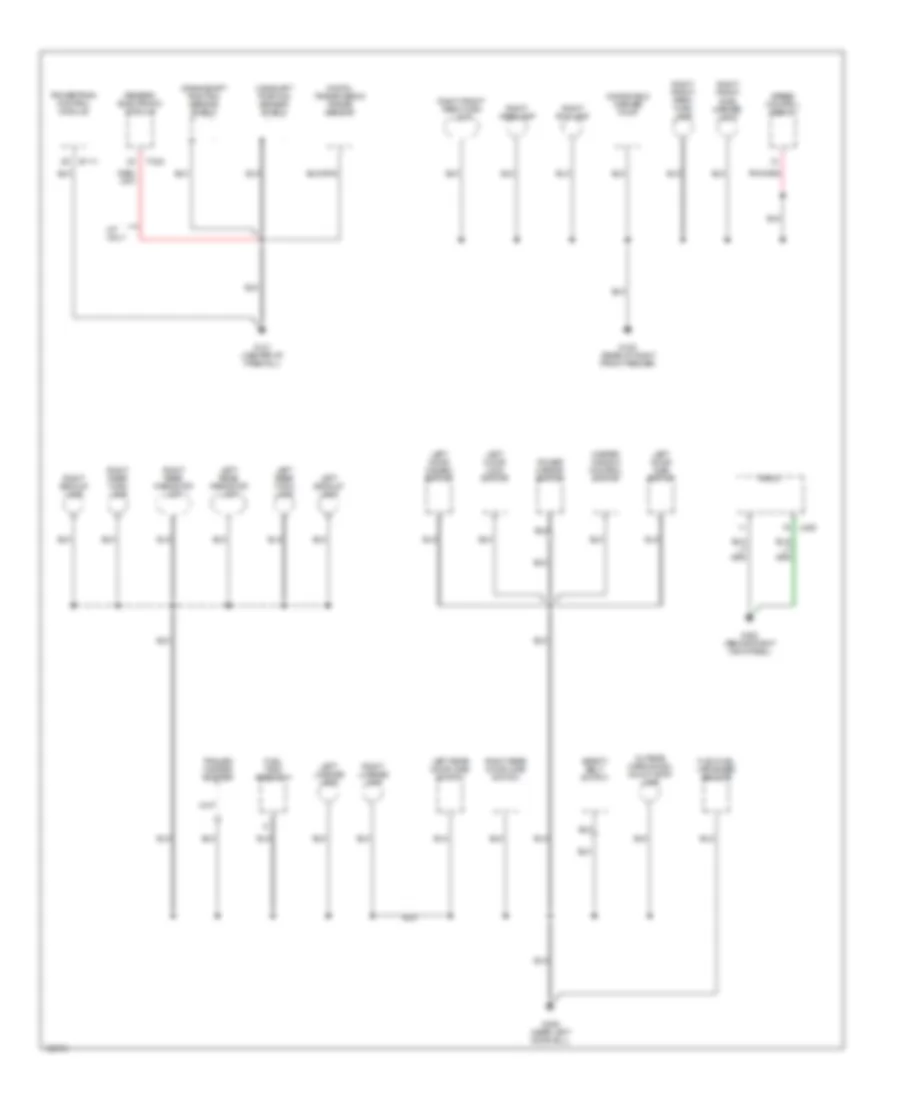
GROUND DISTRIBUTION
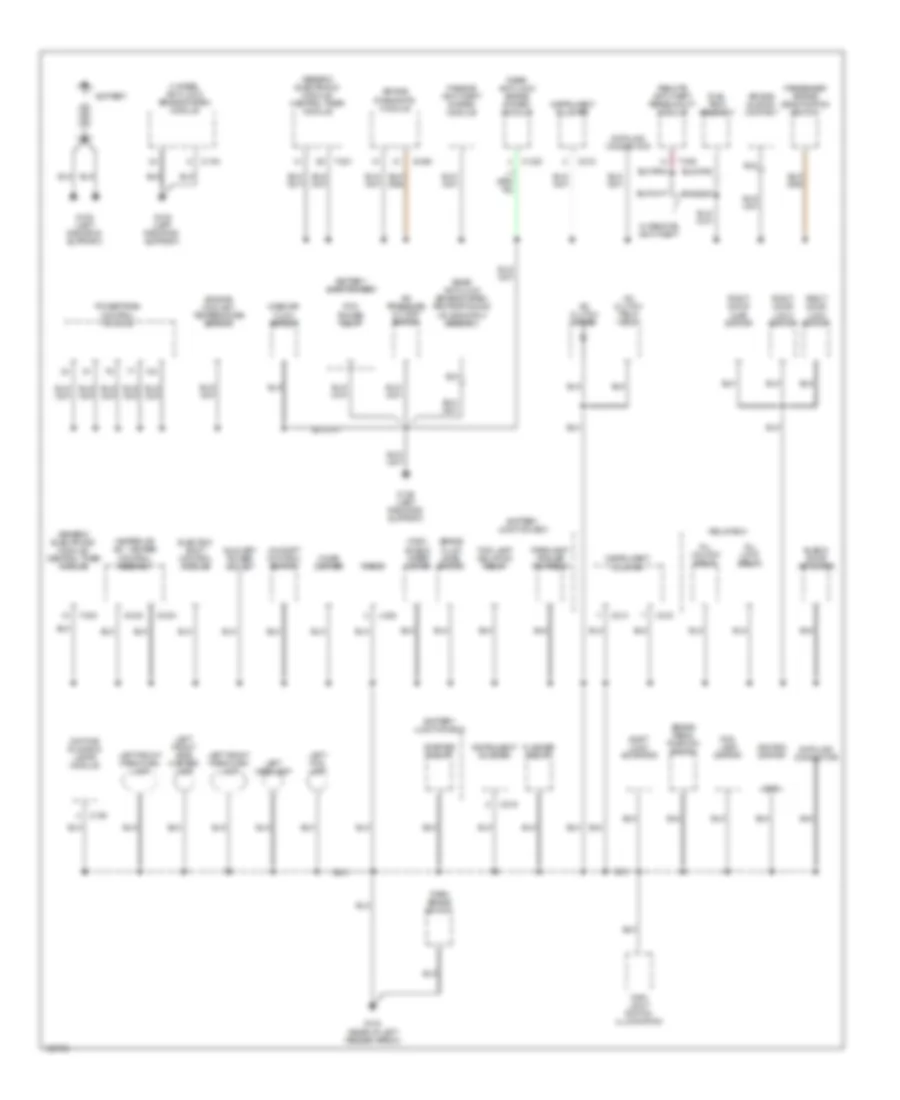
Ground Distribution Wiring Diagram (1 of 2) for Mazda BSE 1999 3000
List of elements for Ground Distribution Wiring Diagram (1 of 2) for Mazda BSE 1999 3000:
- 4 wheel anti-lock brake system module
- 4x4 shift control switch
- A/c clutch diode
- A/c clutch field coil
- A/c pressure cutoff switch
- Air bag diagnostic module
- Air bag sliding contact
- All lock relay
- All unlock relay
- Auxiliary power socket
- Battery
- Battery junction box
- Blend door actuator
- Brake fluid level switch
- Brake pedal position switch
- C150
- C214
- C215
- C216
- Cigar lighter
- Data link connector
- Daytime running lamps module
- Electric shift control module
- Engine coolant temperature sensor
- Flasher relay
- Fog lamp isolation relay
- Fog lamp switch
- Fuel tank assembly
- G-233
- G-234
- G104 (rear of left fender apron)
- G108 (left radiator support)
- Generic electronic module/ central timer module
- Gnd
- Heater or a/c - heater control assembly
- Ignition switch
- Instrument cluster
- J-228
- Left fog lamp
- Left front park/turn lamp
- Left front side marker lamp
- Left headlamp
- Main light switch illumination
- Mass air- flow sensor
- O-154
- O-238
- Park brake switch
- Parklamp/ trailer tow relay
- Passenger air bag deactivation switch
- Passive anti-theft system module
- Pcm power relay
- Powertrain control module
- Radio
- Rear anti-lock brake system module
- Rear anti-lock brake system proportioning valve switch assembly
- Relay box
- Remote anti-theft personality module
- Right door ajar switch
- Right door lock switch
- S-250
- Shift lock actuator
- Starter relay
- T-221
- T-224
- T-409
- W/ remote anti-theft
- Wind- shield wiper motor
Ground Distribution Wiring Diagram (2 of 2) for Mazda BSE 1999 3000
List of elements for Ground Distribution Wiring Diagram (2 of 2) for Mazda BSE 1999 3000:
- B-111
- Camshaft position sensor shield
- Crankshaft position sensor shield
- Digital transmission range sensor
- Flex fuel vaporized sensor
- Fuel tank assembly
- G105 (rear of right front fender)
- G121 (center of firewall)
- G203 (behind right kick panel)
- G309 (near left door sill)
- Generic electronic module
- J-228
- Left backup lamp
- Left door ajar switch
- Left door disarm switch
- Left door lock switch
- Left license lamp
- Left rear door ajar switch
- Left rear park/stop lamp
- Left rear turn lamp
- M/t only
- Master window control switch
- Outside cargo/high mount stop lamp
- Power mirror switch
- Powertrain control module
- Radio
- Right backup lamp
- Right fog lamp
- Right front park/ turn lamp
- Right front park/turn lamp
- Right front side marker light
- Right headlamp
- Right license lamp
- Right rear door ajar switch
- Right rear park/stop lamp
- Right rear turn lamp
- Safety belt switch
- Speed control servo
- T-223
- Trailer/ camper adapter
- Windshield washer pump
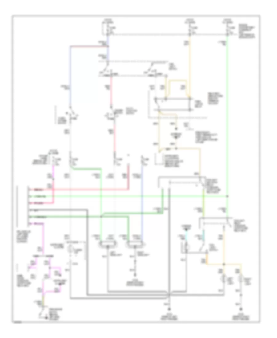
HEADLIGHTS
Headlight Wiring Diagram, with DRL for Mazda BSE 1999 3000
List of elements for Headlight Wiring Diagram, with DRL for Mazda BSE 1999 3000:
- 4wabs
- C215
- Dimmer switch
- Drl module (left side of lower radiator support)
- Engine compartment fuse/relay box (left rear of engine compt)
- Exterior lights
- Flash- to-pass switch
- Fog- light switch
- Foglight isolation relay (in engine compt fuse/ relay box)
- Foglight relay (in engine compt fuse/ relay box)
- Fuse 10a
- Fuse 10a
- Fuse 15a
- Fuse 30a
- G104 (rear of left front fender)
- G105 (rear of right front fender)
- Head
- Hi beam ind
- Hot at all times
- I/p fuse panel (behind left side of dash)
- Instrument cluster
- Instrument illumination dimming module (behind left side of dash)
- Interior lights
- Left fog- light
- Left headlight
- Main light switch
- Multi- function switch
- Off
- Park
- Park brake switch (behind left side of dash)
- Park lights relay
- Pass
- Rabs
- Rabs diode (in engine compt fuse/ relay box)
- Relay box (behind dash, right of steering column)
- Remote anti- theft personality (rap) module (left rear corner of cab)
- Right fog- light
- Right headlight
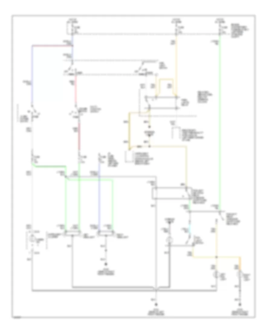
Headlight Wiring Diagram, without DRL for Mazda BSE 1999 3000
List of elements for Headlight Wiring Diagram, without DRL for Mazda BSE 1999 3000:
- C215
- Dimmer switch
- Engine compartment fuse/relay box (left rear of enigne compt)
- Exterior lights
- Flash- to-pass switch
- Fog light switch
- Foglight isolation relay (in engine compt fuse/ relay box)
- Foglight relay (in engine compt fuse/ relay box)
- Fuse 10a
- Fuse 10a
- Fuse 15a
- Fuse 30a
- G104 (rear of left front fender)
- G105 (rear of right front fender)
- Head
- Hi beam ind
- Hot at all times
- I/p fuse panel (behind left side of dash)
- Instrument cluster
- Instrument illumination dimming module (behind left side of dash)
- Interior lights
- Left fog- light
- Left headlight
- Main light switch
- Multi- function switch
- Off
- Park
- Park lights relay
- Pass
- Relay box (behind dash, right of steering column)
- Remote anti- theft personality (rap) module (left rear corner of cab)
- Right fog- light
- Right headlight
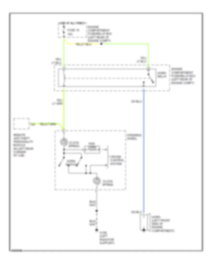
HORN
Horn Wiring Diagram for Mazda BSE 1999 3000
List of elements for Horn Wiring Diagram for Mazda BSE 1999 3000:
- 15a
- Clock spring
- Cruise control system
- Engine compartment fuse/relay box (left rear of engine compt)
- Fuse 10
- G108 (left radiator support)
- Horn (left front side of engine compartment)
- Horn relay
- Horn switch
- Hot at all times
- Ohms
- Remote anti-theft personality module (in left rear corner of cab)
- Steering wheel
INSTRUMENT CLUSTER
Instrument Cluster Wiring Diagram for Mazda BSE 1999 3000
List of elements for Instrument Cluster Wiring Diagram for Mazda BSE 1999 3000:
- (in engine compt fuse/relay box) low fluid resistor (rabs)
- 4wabs
- 4wd hi range indicator
- 4wd low range indicator
- Acc
- Air bag indi- cator
- Anti- slosh module
- Anti-lock brake indicator
- Anti-lock brakes system
- Anti-lock brakes system (rabs)
- Anti-theft system
- Body computer system
- Brake fluid level sensor (brake fluid reser- voir)
- Brake indicator
- C214
- C215
- C216
- C223
- Charge indi- cator
- Charging system
- Check gauge
- Cruise control indicator
- Cruise control system
- Door ajar indicator
- Engine controls system
- Engine coolant temperature sender (2.5l/4.0l: right front of engine; 3.0l: top right of engine)
- Exterior lights system
- Fuel meter
- Fuel reset switch indicator
- Fuel tank assembly (top center of fuel tank)
- Fuse 15a
- Fuse 7.5a
- G104 (rear of left fender apron)
- G108 (left radiator support)
- General electronic module (gem) (behind center of dash)
- Gnd
- Head
- Headlights system
- Headlights system (drl)
- High beam indi- cator
- Hot at all times
- Hot in hi or pass
- Hot in run or start
- I/p fuse panel (behind left side of dash)
- Ignition switch
- Inertia fuel shut-off (ifs) switch (below right side of dash, near kick panel)
- Instrument cluster
- Instrument cluster illumination
- Instrument illumination dimming module (behind left side of dash)
- Interior lights system (instrument illumination)
- Left turn indicator
- Lock
- Main light switch
- Multi-function indicator lamp (mil)
- Nca
- Off
- Oil meter
- Oil pressure sender (4.0l: lower left front of engine; 3.0l: right rear of engine; 2.5l: left rear of cylinder head)
- Overdrive indicator
- Park
- Park brake switch (on park brake assembly)
- Powertrain control module (pcm) (right rear of engine compt, through firewall)
- Rabs
- Rabs diode (in engine compt fuse/relay box)
- Red
- Right turn indicator
- Run
- Seat belt indicator
- Speedometer
- Start
- Tachometer
- Temp meter
- Theft indi- cator
- Voltmeter
- Warning systems
INTERIOR LIGHTS
Courtesy Lamps Wiring Diagram for Mazda BSE 1999 3000
List of elements for Courtesy Lamps Wiring Diagram for Mazda BSE 1999 3000:
- Base model
- Battery saver relay
- Dome light
- Dome/ map light
- Except base model
- Exterior lights system
- Fuse 26 10a
- G104 (rear of left fender apron)
- G309 (near left door sill)
- Generic electronic module (gem)/ central timer module (ctm) (behind center of dash)
- High mount stop light
- Hot at all times
- I/p fuse panel (behind left side of dash)
- Instrument illumination dimming module (behind left side of dash)
- Interior light relay
- Left door ajar switch
- Outside cargo light
- Outside cargo/ high mount stoplight
- Relay box (behind dash, right of steering column)
- Right door ajar switch
- T-221
- T-224
Instrument Illumination Wiring Diagram for Mazda BSE 1999 3000
List of elements for Instrument Illumination Wiring Diagram for Mazda BSE 1999 3000:
- 4 x 4 shift control switch illumination
- A/c-heater or heater control assembly illumination
- C214
- C215
- C233
- Clockspring assembly (top of steering column)
- Courtesy lamps circuit
- Cruise control switch assembly illumination
- Dome
- Engine compartment fuse/relay box (left rear of engine compt)
- Exterior lights system
- Foglight switch illumination
- Fuse 11 15a
- G104 (rear of left front fender apron)
- G104 (rear of left front fender)
- G108 (left radiator support)
- Generic electronic module (gem)
- Head
- Hot at all times
- Illumination
- Instrument cluster illumination
- Instrument illumination dimming module (behind left side of dash)
- Main light switch
- Nca
- Off
- Park
- Park lights relay (in relay box)
- Radio illumination
- Remote anti-theft personality (rap) module (left rear corner of cab)
- Solid state
POWER DISTRIBUTION
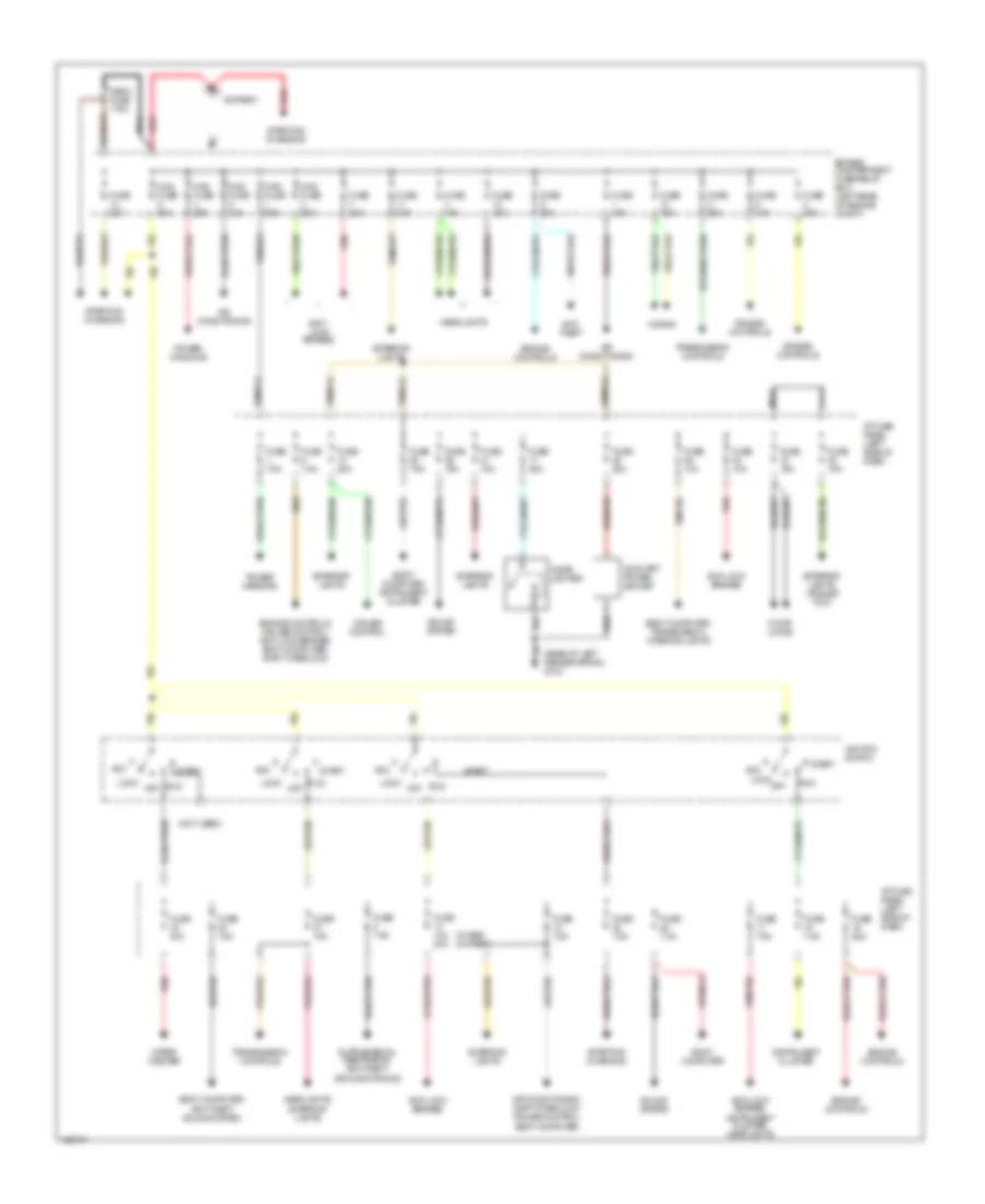
Power Distribution Wiring Diagram for Mazda BSE 1999 3000
List of elements for Power Distribution Wiring Diagram for Mazda BSE 1999 3000:
- (not used)
- (rear of left fender apron) g104
- (w/ abs) (w/ rabs)
- Acc
- Air conditioning
- Air conditioning, shift interlock, cruise control, body computer
- Anti- lock brakes
- Anti- theft
- Anti-lock brakes
- Anti-lock brakes, instrument cluster, headlights
- Auxiliary power socket
- Battery
- Body computer
- Body computer, anti-theft sound system
- Body computer, instrument cluster
- Body computer, transmission, interior lights
- Cigar lighter
- Cruise control
- Door locks
- Engine compartment fuse/relay box (left rear of engine compt)
- Engine controls
- Engine controls, cruise control, anti-lock brakes, body computer, shift interlock
- Exterior lights
- Exterior lights (trailer tow)
- Fuse 10a
- Fuse 10a 20a
- Fuse 15a
- Fuse 20a
- Fuse 25a
- Fuse 30a
- Fuse 7.5a
- Headlights
- Headlights, exterior lights
- Horns
- I/p fuse panel (left side of dash)
- Ignition switch
- Instrument cluster
- Lock
- Maxi fuse 20a
- Maxi fuse 40a
- Maxi fuse 50a
- Mega fuse 175a
- Nca
- Off
- Power mirrors
- Power windows
- Red
- Run
- Sound system
- Start
- Starting/ charging
- Transmission controls
- Wiper/ washer
POWER DOOR LOCKS
Power Door Lock Wiring Diagram for Mazda BSE 1999 3000
List of elements for Power Door Lock Wiring Diagram for Mazda BSE 1999 3000:
- (near left door sill) g309
- (rear of left fender apron) g104
- 1996 vftc c
- All lock relay (in relay box)
- All unlock relay (in relay box)
- C409
- C410
- Driver's unlock relay (behind right side of dash)
- Fuse 15a
- G104 (rear of left fender apron)
- Hot at all times
- I/p fuse panel
- Left door lock motor
- Left door lock switch
- Lock
- Remote anti-theft personality (rap) module (in left rear corner of cab)
- Right door lock motor
- Right door lock switch
- Unlock
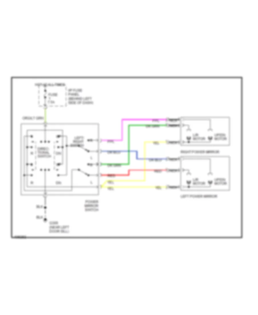
POWER MIRRORS
Power Mirror Wiring Diagram for Mazda BSE 1999 3000
List of elements for Power Mirror Wiring Diagram for Mazda BSE 1999 3000:
- Direc- tional switch
- Fuse 7.5a
- G309 (near left door sill)
- Hot at all times
- I/p fuse panel (behind left side of dash)
- L/r motor
- Left power mirror
- Left/ right switch
- Nca
- Power mirror switch
- Red
- Right power mirror
- Up/dn motor
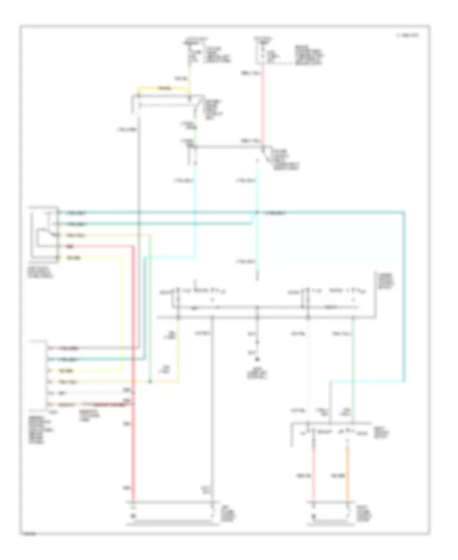
POWER WINDOWS
Power Window Wiring Diagram for Mazda BSE 1999 3000
List of elements for Power Window Wiring Diagram for Mazda BSE 1999 3000:
- 1996 vftc c
- Battery saver relay (in relay box)
- C224
- Down
- Engine compartment fuse/relay box (left rear of engine compt)
- Fuse 10a
- G309 (near left door sill)
- Generic electronic control module (gem) (behind center of dash)
- Hot at all times
- Hot in accy
- I/p fuse panel (behind left side of dash)
- Left
- Left power window motor
- Master window control switch
- Maxi fuse 4 20a
- One touch down relay (in relay box)
- Or run
- Power window relay (under right side of dash)
- Red
- Resistor (.015 ohms) (1999)
- Right
- Right power window motor
- Right window switch
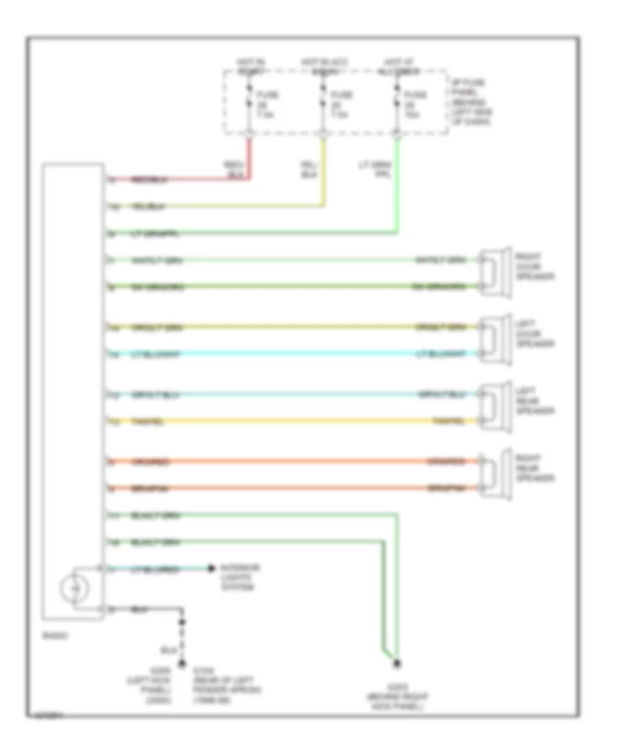
RADIO
Radio Wiring Diagrams for Mazda BSE 1999 3000
List of elements for Radio Wiring Diagrams for Mazda BSE 1999 3000:
- Fuse 15a
- Fuse 7.5a
- G104 (rear of left fender apron) (1998-99)
- G200 (left kick panel) (2000)
- G203 (behind right kick panel)
- Hot at all times
- Hot in acc & run
- Hot in start
- I/p fuse panel (behind left side of dash)
- Interior lights system
- Left door speaker
- Left rear speaker
- Radio
- Right door speaker
- Right rear speaker
SHIFT INTERLOCKS
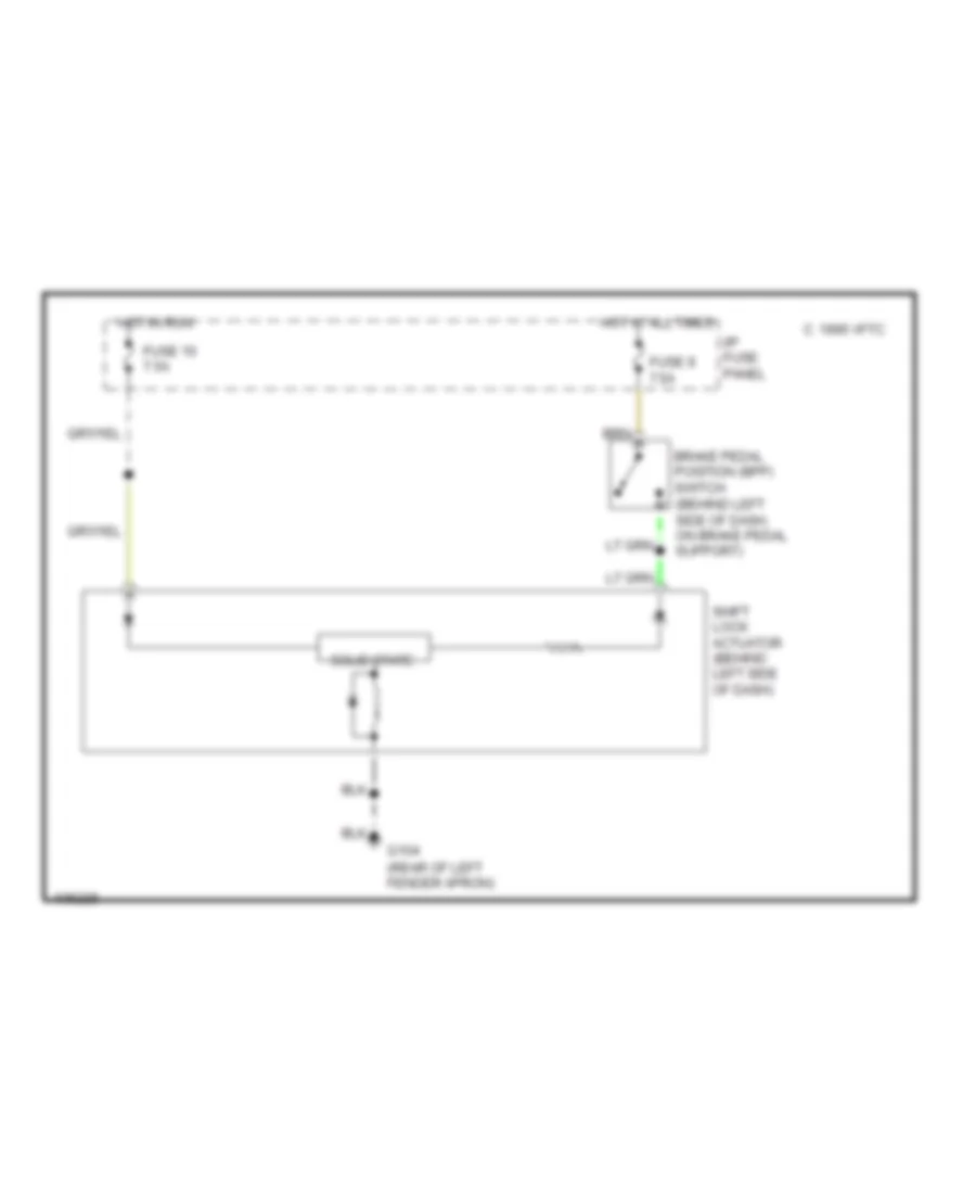
Shift Interlock Wiring Diagram for Mazda BSE 1999 3000
List of elements for Shift Interlock Wiring Diagram for Mazda BSE 1999 3000:
- (behind left side of dash, on brake pedal support)
- Brake pedal position (bpp) switch
- C 1995 vftc
- Fuse 10 7.5a
- Fuse 9 7.5a
- G104 (rear of left fender apron)
- Hot at all times
- Hot in run
- I/p fuse panel
- Shift lock actuator (behind left side of dash)
- Solid state
STARTING/CHARGING
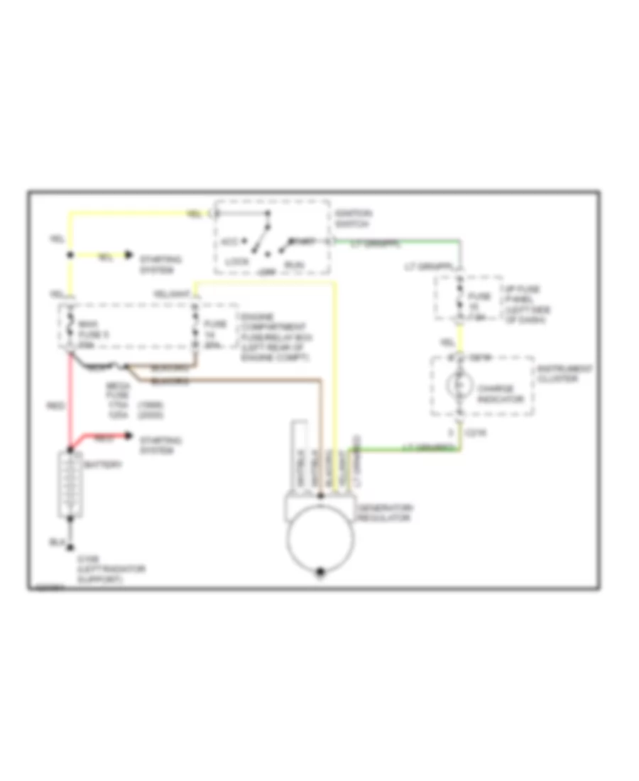
Charging Wiring Diagram for Mazda BSE 1999 3000
List of elements for Charging Wiring Diagram for Mazda BSE 1999 3000:
- (1999) (2000)
- Acc
- Battery
- C216
- Charge indicator
- Engine compartment fuse/relay box (left rear of engine compt)
- Fuse 30a
- Fuse 7.5a
- G108 (left radiator support)
- Generator/ regulator
- I/p fuse panel (left side of dash)
- Ignition switch
- Instrument cluster
- Lock
- Maxi fuse 5 50a
- Mega fuse 175a 125a
- Nca
- Off
- Red
- Run
- Start
- Starting system
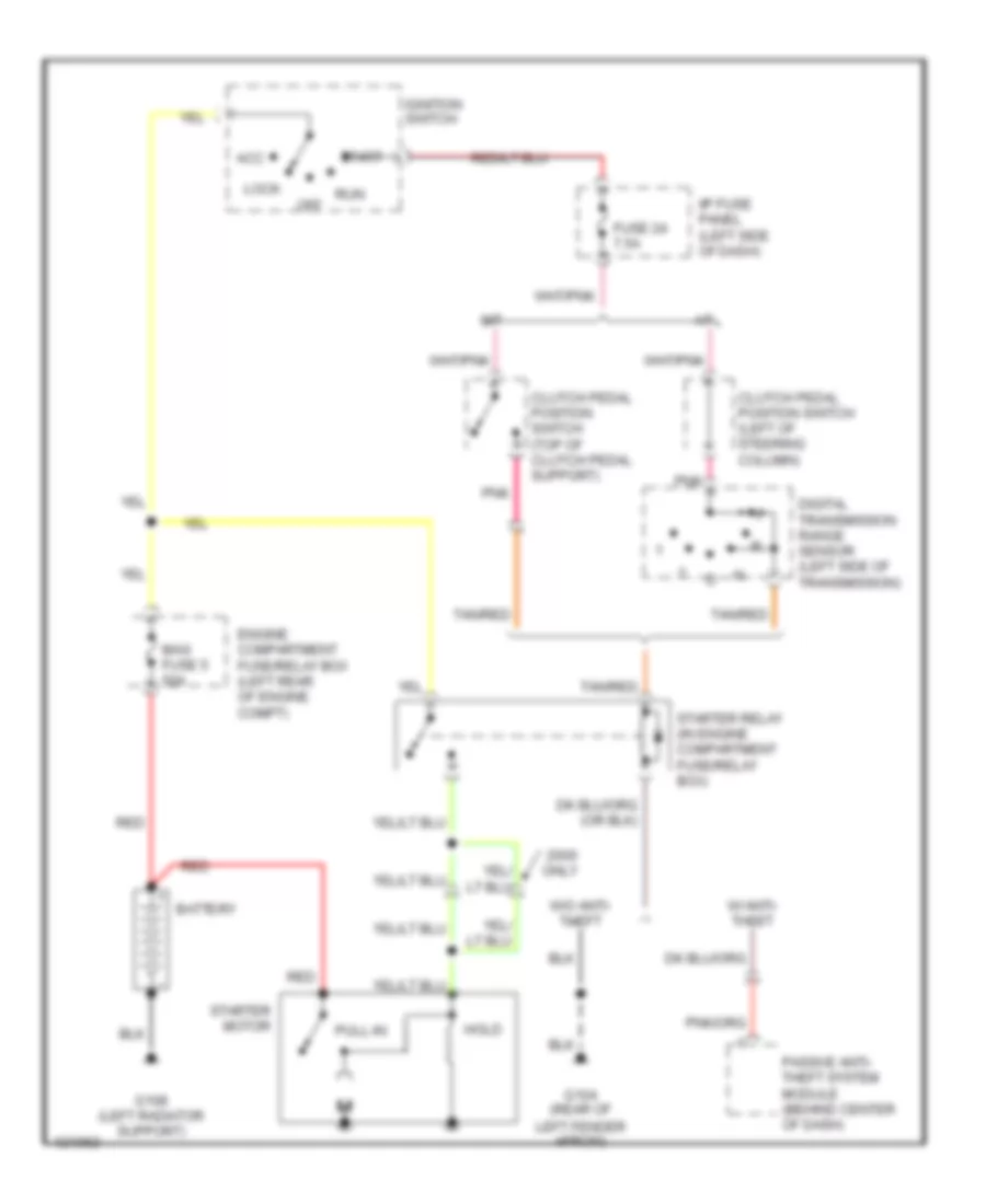
Starting Wiring Diagram for Mazda BSE 1999 3000
List of elements for Starting Wiring Diagram for Mazda BSE 1999 3000:
- A/t
- Acc
- Battery
- Clutch pedal position switch (left of steering column)
- Clutch pedal position switch (top of clutch pedal support)
- Digital transmission range sensor (left side of transmission)
- Engine compartment fuse/relay box (left rear of engine compt)
- Fuse 24 7.5a
- G104 (rear of left fender apron)
- G108 (left radiator support)
- Hold
- I/p fuse panel (left side of dash)
- Ignition switch
- Lock
- M/t
- Maxi fuse 5 50a
- Off
- Only
- Passive anti- theft system module (behind center of dash)
- Pnk
- Pull-in
- Red
- Run
- Start
- Starter motor
- Starter relay (in engine compartment fuse/relay box)
- Tan/red
- W/ anti- theft
- W/o anti- theft
SUPPLEMENTAL RESTRAINTS
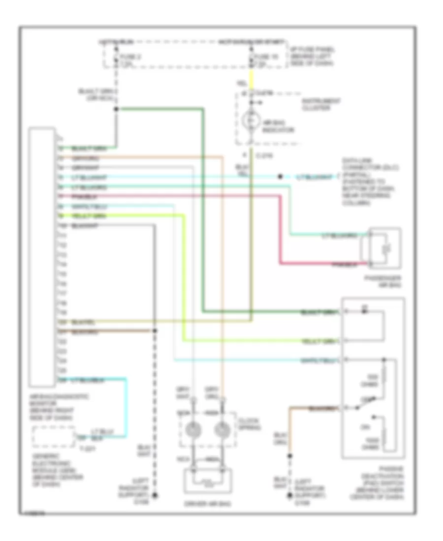
Supplemental Restraint Wiring Diagram for Mazda BSE 1999 3000
List of elements for Supplemental Restraint Wiring Diagram for Mazda BSE 1999 3000:
- (left radiator support) g108
- Air bag diagnostic monitor (behind right side of dash)
- Air bag indicator
- C-216
- Clock spring
- Data link connector (dlc) (partial) (fastened to bottom of dash, near steering column)
- Driver air bag
- Fuse 15 7.5a
- Fuse 2 7.5a
- Generic electronic module (gem) (behind center of dash)
- Hot in run
- Hot in run or start
- I/p fuse panel (behind left side of dash)
- Instrument cluster
- Nca
- Off
- Ohms
- Passenger air bag
- Passive deactivation (pad) switch (behind lower center of dash)
- T-221
TRANSMISSION
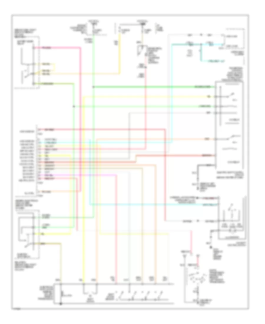
4WD Wiring Diagram for Mazda BSE 1999 3000
List of elements for 4WD Wiring Diagram for Mazda BSE 1999 3000:
- (behind dash, right side of steering column) relay box
- (rear of left front fender apron) g104
- 1.1k ohms
- 3.0l/ 4.0l only
- 3.9k ohms
- 4wd hi ind
- 4wd ind ctrl
- 4wd lo ind
- 4wd mode sw
- 4wd output
- 4x4 shift control switch
- A/t
- Battery saver relay
- Bpp sw input
- Brake pedal position (bpp) switch (on brake pedal support)
- C214
- Ccw relay
- Ccw rly ctrl
- Clutch
- Cw relay
- Cw rly ctrl
- Digital transmission range (dtr) sensor (left side of transmission)
- Elc rly ctrl
- Electric shift control module (behind center of dash)
- Electric shift relay
- Electronic shift motor assembly (on left rear of transmission)
- Engine compartment fuse/relay box
- Firewall) g121
- Fuse 26 10a
- Fuse 3 20a
- Fuse 9 7.5a
- G104 (rear of left fender apron)
- Generic electronic module (gem) (behind center of dash)
- Hot at all times
- I/p fuse panel
- Illumination
- Instrument cluster
- Interior lights system (instrument illum- ination circuit)
- M/t
- Neutral sw in
- Ohms
- Powertrain contrtol module (pcm) (right rear of of eng compt through firewall)
- Relay box (behind dash, right side of steering column)
- Rly ctrl
- Shift motor
- Shift motor sensor
- Sw a input
- Sw b input
- Sw c input
- Sw d input
- T-221
- T-223
- T-224
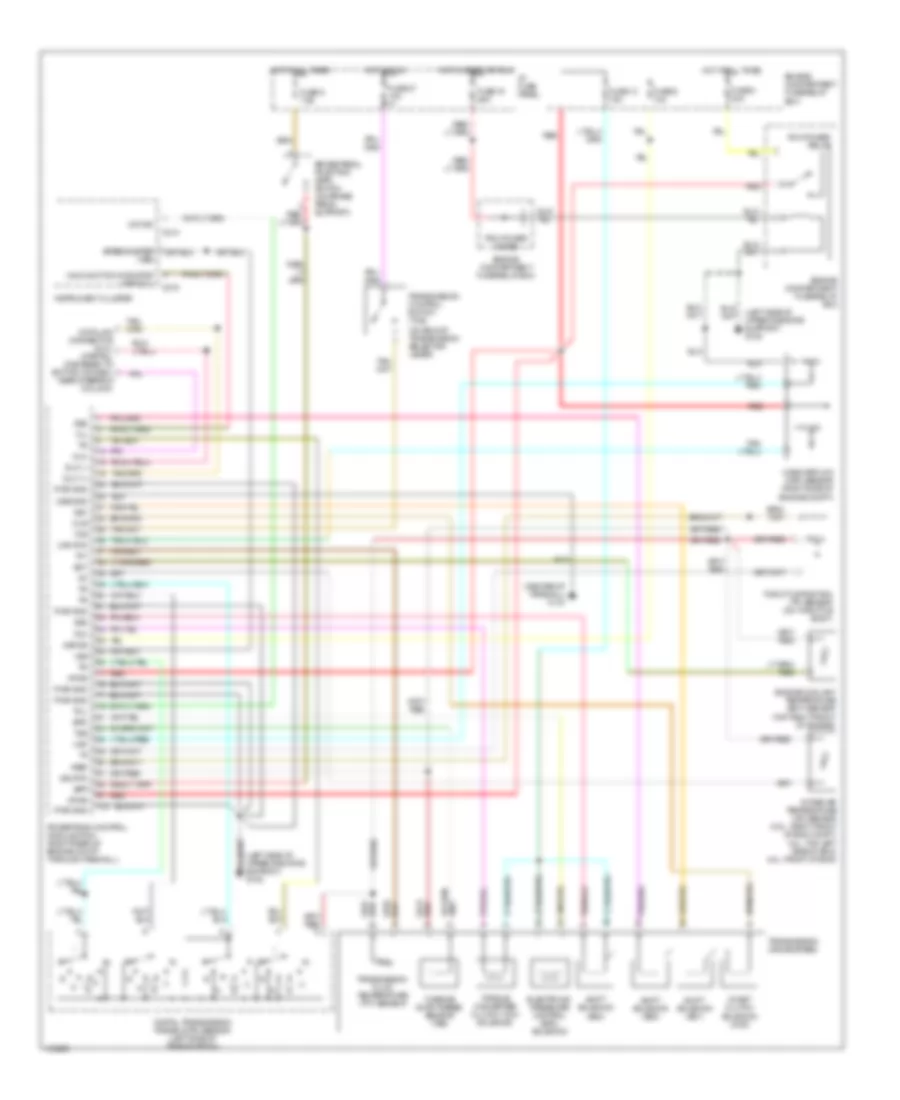
A/T Wiring Diagram for Mazda BSE 1999 3000
List of elements for A/T Wiring Diagram for Mazda BSE 1999 3000:
- (center of firewall) g121
- (left side of upper radiator support) g108
- (on end of transmission selector lever)
- Bpp
- Brake pedal postition (bpp) switch (on brake pedal support)
- C214
- C215
- Ccs
- Coast clutch solenoid (ccs)
- Cse gnd
- Data link connector (dlc) (partial) (fastened to bottom of dash, near steering column)
- Digital transmission range (dtr) sensor (left side of transmission)
- Dlc
- Dlc (+)
- Dlc (-)
- Ect
- Electronic pressure control (epc) solenoid
- Engine compartment fuse/relay box
- Engine coolant temperature (ect) sensor (top right front of engine)
- Epc
- Fuse 13 15a
- Fuse 19 25a
- Fuse 27 10a
- Fuse 6 10a
- Fuse 8 30a
- Fuse 9 7.5a
- Hot at all times
- Hot in run
- Hot in start or run
- I/p fuse panel
- Iat
- Instrument cluster
- Intake air temperature (iat) sensor (2.5l : right front of eng compt, 3.0l: top left side of eng, 4.0l: front of eng)
- Kapwr
- Maf
- Maf rtn
- Malfunction indicator lamp (mil)
- Mass airflow (maf) sensor (right side of engine compt)
- Mil
- O/d ind
- Pcm power diode
- Pcm power relay
- Powertrain control module (pcm) (right rear of engine compt through firewall)
- Pwr gnd
- Red
- Shift solenoid (ss1)
- Shift solenoid (ss2)
- Shift solenoid (ss3)
- Sig rtn
- Speedometer (vss)
- Ss1
- Ss2
- Ss3
- Tcc
- Tcil
- Tcs
- Tft
- Throttle position (tp) sensor (on throttle body)
- Torque converter clutch (tcc) solenoid
- Transmission (4r44e 5r55e)
- Transmission control switch (tcs)
- Transmission fluid temperature (tft) sensor
- Tss
- Turbine shaft speed sensor (tss)
- Vpwr
- Vref
- Vss
WARNING SYSTEMS
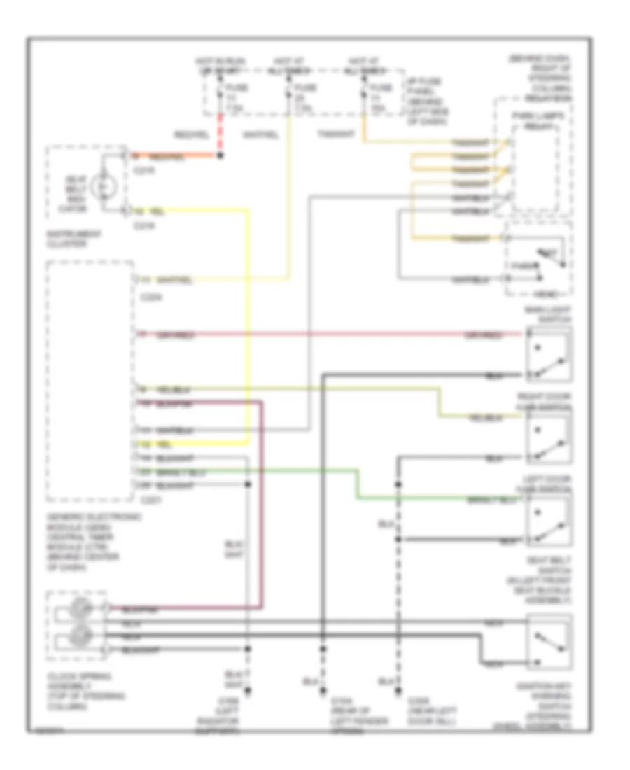
Warning System Wiring Diagrams for Mazda BSE 1999 3000
List of elements for Warning System Wiring Diagrams for Mazda BSE 1999 3000:
- (behind dash, right of steering column) relay box
- C215
- C216
- C221
- C224
- Clock spring assembly (top of steering column)
- Fuse 15a
- Fuse 7.5a
- G104 (rear of left fender apron)
- G108 (left radiator support)
- G309 (near left door sill)
- Generic electronic module (gem)/ central timer module (ctm) (behind center of dash)
- Head
- Hot at all times
- Hot in run or start
- I/p fuse panel (behind left side of dash)
- Ignition key warning switch (steering wheel assembly)
- Instrument cluster
- Left door ajar switch
- Main light switch
- Nca
- Off
- Park
- Park lamps relay
- Right door ajar switch
- Seat belt indi- cator
- Seat belt switch (in left front seat buckle assembly)
WIPER/WASHER
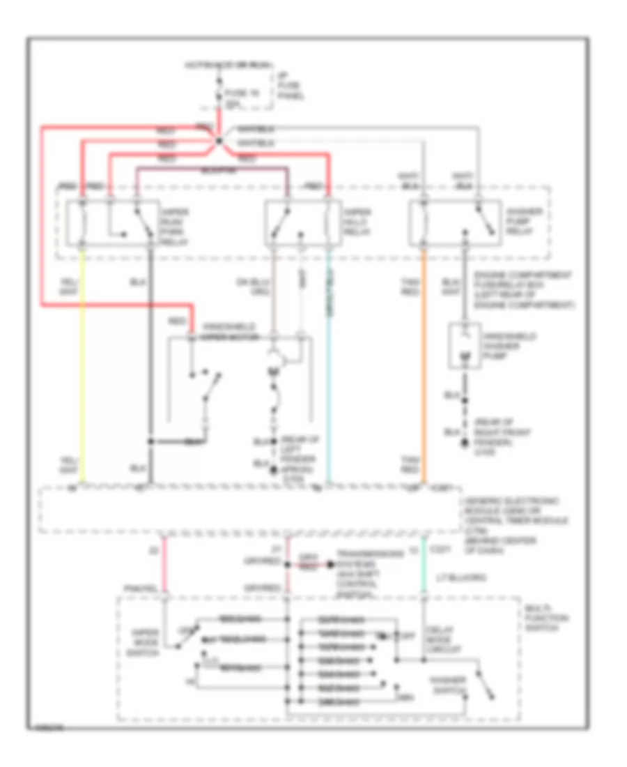
Wiper/Washer Wiring Diagram for Mazda BSE 1999 3000
List of elements for Wiper/Washer Wiring Diagram for Mazda BSE 1999 3000:
- (rear of left fender apron)
- (rear of right front fender) g105
- 1370 ohms
- 1910 ohms
- 1910 ohms int
- 249 ohms
- 2670 ohms
- 402 ohms
- 634 ohms
- 953 ohms
- 955 ohms
- C221
- Delay mode circuit
- Engine compartment fuse/relay box (left rear of engine compartment)
- Fuse 16 30a
- G104
- Generic electronic module (gem) or central timer module (ctm) (behind center of dash)
- Hot in acc or run
- I/p fuse panel
- Lo 401 ohms
- Max
- Min
- Multi- function switch
- Off
- Red
- Tan/ red
- Transmissions systems (4x4 shift control switch)
- Washer pump relay
- Washer switch
- Windshield washer pump
- Windshield wiper motor
- Wiper hi-lo relay
- Wiper mode switch
- Wiper run/ park relay

 Čeština
 Dansk
Dansk Deutsch
 Ελληνικά
 English
 English
 Español
 Suomi
Suomi Français
 Français
 עברית
עברית Hrvatski
 Magyar
 Italiano
 日本語
日本語 한국어
한국어 Nederlands
 Polski
 Português
 Português
 Română
 Русский
 Slovenčina
 Svenska
 Türkçe
 中文 (中国)