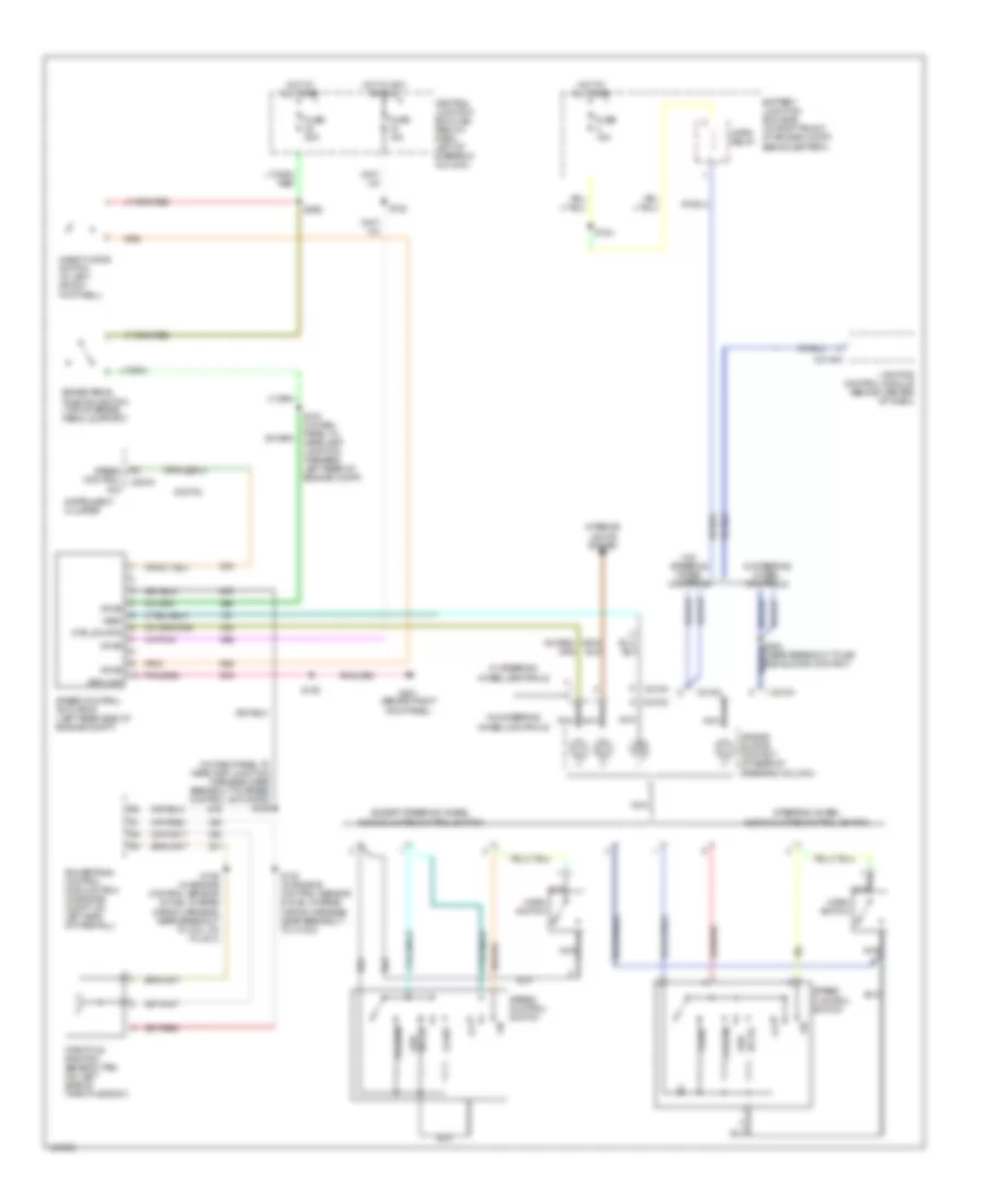
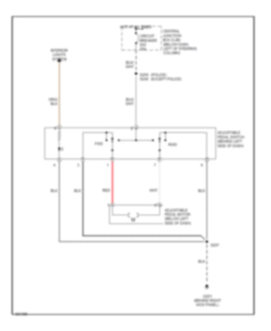
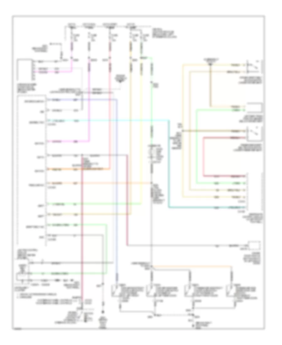
AIR CONDITIONING
Automatic A/C Wiring Diagram for Mercury Grand Marquis GS 2004
 https://portal-diagnostov.com/license.html
Automotive Electricians Portal FZCO
Automotive Electricians Portal FZCO
https://portal-diagnostov.com/license.html
https://portal-diagnostov.com/license.html
Automotive Electricians Portal FZCO
Automotive Electricians Portal FZCO
List of elements for Automatic A/C Wiring Diagram for Mercury Grand Marquis GS 2004:
- (at center rear of engine) g106
- (at front of right front fender apron) g102
- (at front of right front fender apron) g102
- (behind right kick panel) g201
- (in main wiring harness, on left rear side of engine compt) s286
- (left rear of engine compt)
- (left rear of engine compt) s156
- (near breakout to c1019) s109
- (near breakout to c1033) s123
- (near breakout to c1046) s113
- (near breakout to coil on plug 2) s157
- (near breakout to coil on plug 4)
- (near breakout to speed control actuator) s128
- (not used)
- A/c clutch field coil (at right front of engine)
- A/c clutch relay
- A/c evaporator discharge temperature sensor (on right side rear of engine compt)
- A/c pressure transducer sensor (on right side center of engine)
- Air bag sliding contact (at base of steering column)
- Amb temp sens input
- Ambient air temperature sensor (on front of upper radiator support)
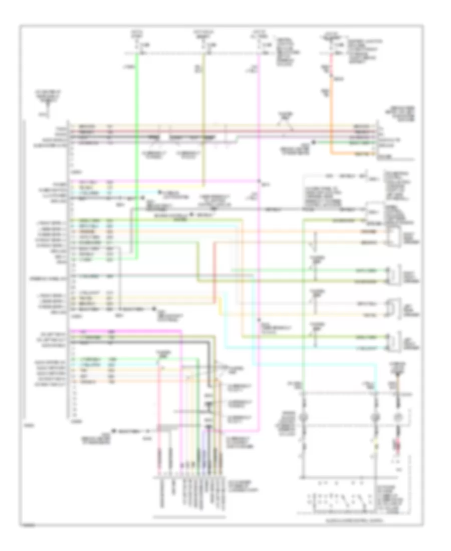
- Audio/climate control system
- Autolamp/sunload sensor (on upper left side of dash)
- Battery
- Battery junction box (bjb) (in right front of engine compartment, behind battery)
- Blend door (heat)
- Blower motor high message center switch out blend door (cool)
- Blower motor relay
- Blower mtr output
- Blower speed ctrl
- C2145a
- C220b
- C228a
- C228b
- Central junction box (cjb) (below dash, left of steering column)
- Computer data lines system
- Control module)
- Eatc module
- Electronic automatic temperature control (eatc) module (behind center of dash)
- Engine controls system
- Engine coolant temperature (ect) sensor (except marauder: on top right front of engine, near fuel injector 1) (marauder: at front top left of engine)
- Engine cooling fan motor (front of engine compt)
- Fan down
- Fan up
- Front blower motor (at right rear of engine compt)
- Front blower motor speed controller (at rear of engine compt)
- Front fender apron) g102
- Front panel illum
- Fuse 15a
- Fuse 40a
- Fuse 50a
- G201 (behind right kick panel)
- Ground
- Hot at all times
- Hot in run
- Hot in run or acc
- Hot in run or start
- Ignition
- In car temp sens
- In-vehicle temperature sensor (behind top center of dash)
- Instrument cluster (electronic cluster)
- Instrument illum
- Interior lights system
- Lighting control module (behind center of dash)
- Low charge protection sw
- Low charge protection switch (at right side of of engine compt)
- Nca
- Pcm power relay
- Powertrain control module (pcm) (in engine compt on left side of firewall)
- Red
- Remote ctrl unit
- Rest
- S113 (in dash panel to headlamp junction harness, near breakout to c1046)
- S122 (in dash panel to headlamp junction harness, left rear of engine compartment)
- S126
- S130 (left rear of engine compt)
- S133 (left rear of engine compt)
- S136
- S141 (in dash panel to headlamp junction harness, near breakout to c1026)
- S142 (in dash panel to headlamp junction harness, in breakout to engine cooling fan motor)
- S227 (in main wiring harness, near breakout to lighting control module)
- S276 (in main wiring harness, near breakout to autolamp sensor)
- S285 (in main wiring harness, near breakout to adjustable pedal switch)
- Scp bus (+)
- Scp bus (-)
- Sensor rtn
- Sunload sens input
- Temp door variable resistor
- Temp down
- Temp up
- Temperature blend door actuator (behind right side of dash, on top of a/c plenum)
- To autolamp sensor)
- Variable resistor
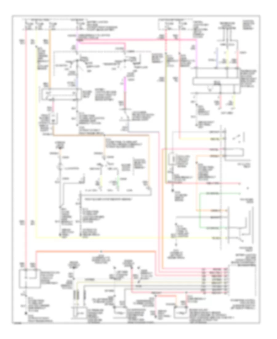
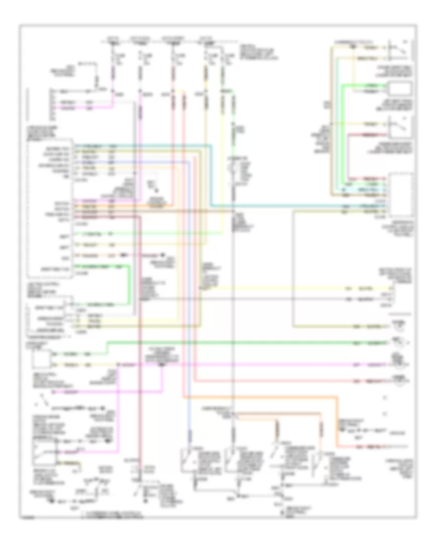
Manual A/C Wiring Diagram for Mercury Grand Marquis GS 2004
List of elements for Manual A/C Wiring Diagram for Mercury Grand Marquis GS 2004:
- (at front of right
- (at front of right front fender apron) g102
- (behind right kick panel) g201
- (front of engine compartment)
- (in engine compt on left side of firewall)
- (near breakout to coil on plug 4)
- (not used)
- A/c clutch field coil (at right front of engine)
- A/c clutch relay
- A/c evaporator discharge air temperature sensor (on right side rear of engine compt)
- A/c pressure transducer sensor (on right side center of engine)
- A/c switch
- Battery junction box (bjb) (in right front of engine compartment, behind battery)
- Battery junction box (bjb) (in right front of engine compt, behind battery)
- Blower motor relay
- Blower motor switch
- C294a
- C294b
- C294c
- C294d
- Central junction box (cjb) (below dash, left of steering column)
- Cold
- Compt)
- Control module) s266
- Def
- Def/floor
- Engine controls system
- Engine coolant temperature (ect) sensor (except marauder: on top right front of engine, near fuel injector 1) (marauder: at front top left of engine)
- Engine cooling fan motor
- Floor
- Front blower motor (at right rear of engine
- Front blower motor resistor assembly
- Front fender apron)
- Function selector switch assembly
- Fuse 15a
- Fuse 25a
- Fuse 30a
- Fuse 40a
- Fuse 50a
- G101 (at rear of left front fender apron)
- G102
- G102 (at front of right
- G106 (at center rear of engine)
- High
- Hot at all times
- Hot in run
- Hot in start or run
- Illumination
- Interior lights system
- Low
- Low charge protection switch (at right side of engine compt)
- Max
- Med high
- Med low
- Mode switch
- Off
- Panel
- Panel/ floor
- Pcm power diode
- Pcm power relay
- Powertrain control module (pcm)
- S109 (in dash panel to headlamp junction harness, near breakout to c1019)
- S113 (in dash panel to headlamp junction harness, near breakout
- S113 (in dash panel to headlamp junction harness, near breakout to c1046)
- S117 (near breakout to c1010)
- S123 (near breakout to c1033)
- S126
- S128 (near breakout to speed control actuator)
- S142 (in breakout to engine cooling fan motor)
- S144 (in dash panel to headlamp junction harness, in breakout to front blower motor)
- S157 (near breakout to coil on plug 2)
- S204 (in main wiring harness, near breakout to clock)
- S204 (near breakout to clock)
- S276 (in main wiring harness, near breakout to autolamp sensor)
- S276 (near breakout to autolamp sensor)
- Solid state
- Temperature blend door actuator (behind right side of dash, on top of a/c plenum)
- Temperature control potentiometer
- To c1046)
- Warm
ANTI-LOCK BRAKES
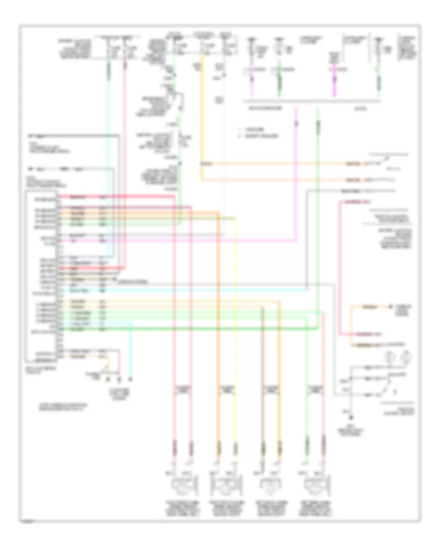
Anti-lock Brakes Wiring Diagram for Mercury Grand Marquis GS 2004
List of elements for Anti-lock Brakes Wiring Diagram for Mercury Grand Marquis GS 2004:
- Abs ind
- Analog/marauder
- Anti-lock brake module
- Anti-lock ind
- Battery
- Battery junction box (bjb) (in right front of engine compt, behind battery)
- Bpp switch
- Brake pedal position switch (top of brake pedal support)
- C220c
- C2220a
- C2220b
- Central junction box (cjb) (below dash, left of steering column)
- Computer data lines system
- Digital
- Except marauder
- Fuse 10a
- Fuse 15a
- Fuse 20a
- Fuse 40a
- Fuse 5a
- G101 (at rear of left front fender apron)
- G102 (at front of right front fender apron)
- G201 (behind right kick panel)
- Ground
- Hot at all times
- Hot in run
- Hot in run or acc
- Ign
- Ignition
- Illumination
- Indicator
- Instrument cluster
- Interior lights system
- Iso
- Left front wheel speed sensor (at left side of engine compt)
- Left rear wheel speed sensor (forward of left rear wheelwell)
- Lf sensor
- Lr sensor
- Marauder
- Note: there is a shorting bar across pins 15 & 16
- Red
- Red/pnk
- Rf sensor
- Right front wheel speed sensor (at right side of engine compt)
- Right rear wheel speed sensor (forward of right rear wheelwell)
- Rr sensor
- S112
- S132 (in dash panel to headlamp junction harness, left rear of engine compt)
- S154
- S224
- S231
- S265
- Scp bus (+)
- Scp bus (-)
- Tc ind
- Tc ind relay
- Tc sw in
- Tract asst ind
- Tract asst input
- Traction control indicator relay
- Traction control switch
- Twisted pair
- Warning
- Warning lamps module (behind left side of dash)
- Warning system
ANTI-THEFT
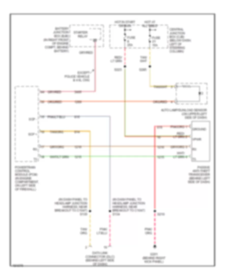
Anti-theft Wiring Diagram for Mercury Grand Marquis GS 2004
List of elements for Anti-theft Wiring Diagram for Mercury Grand Marquis GS 2004:
- (in dash panel to headlamp junction harness, near breakout to c1047) s134
- (in dash panel to headlamp junction harness, near breakout to c1047) s135
- Auto lamp/sunload sensor (on upper left side of dash)
- Battery junction box (bjb) (in right front of engine compt, behind battery)
- Central junction box (cjb) (below dash, left of steering column)
- Data link connector (dlc) (behind left side of dash)
- Except police vehicle & 4.6l cng
- Fuse 15a
- Fuse 25a
- G201 (behind right kick panel)
- Ground
- Hot at all times
- Hot in start or run
- Passive anti-theft transceiver (behind left side of dash)
- Powertrain control module (pcm) (in engine compartment, on left side of firewall)
- S210
- S223
- S285
- Scp +
- Scp -
- Starter relay
- Vpwr
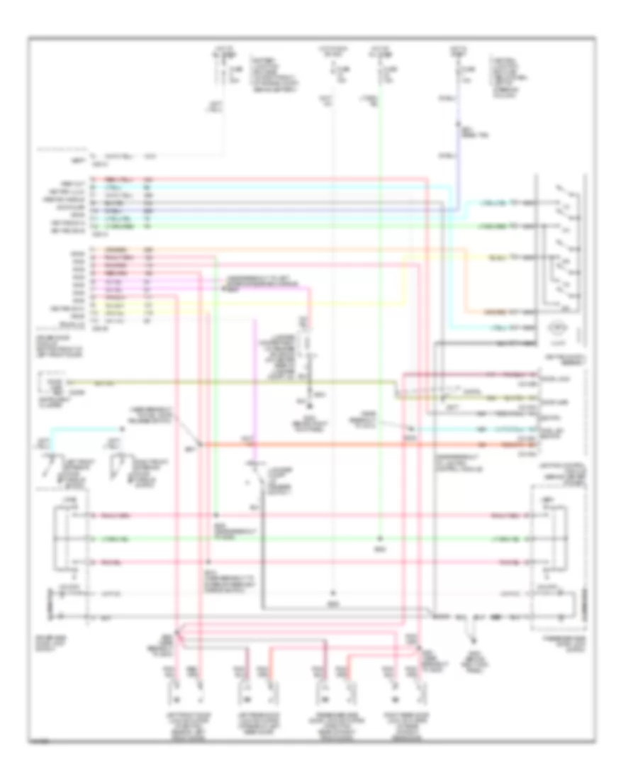
BODY CONTROL MODULES
Body Control Modules Wiring Diagram for Mercury Grand Marquis GS 2004
List of elements for Body Control Modules Wiring Diagram for Mercury Grand Marquis GS 2004:
- (behind right kick panel) (w/o keyless entry) g201 g202 (w/ keyless entry) (behind left kick panel)
- Battery junction box (bjb) (in right front of engine compartment, behind battery)
- C2145a
- C2145c
- C220b
- C501a
- C501b
- C501c
- Central junction box (cjb) (below dash, left of steering column)
- Computer data lines system
- Digital cluster
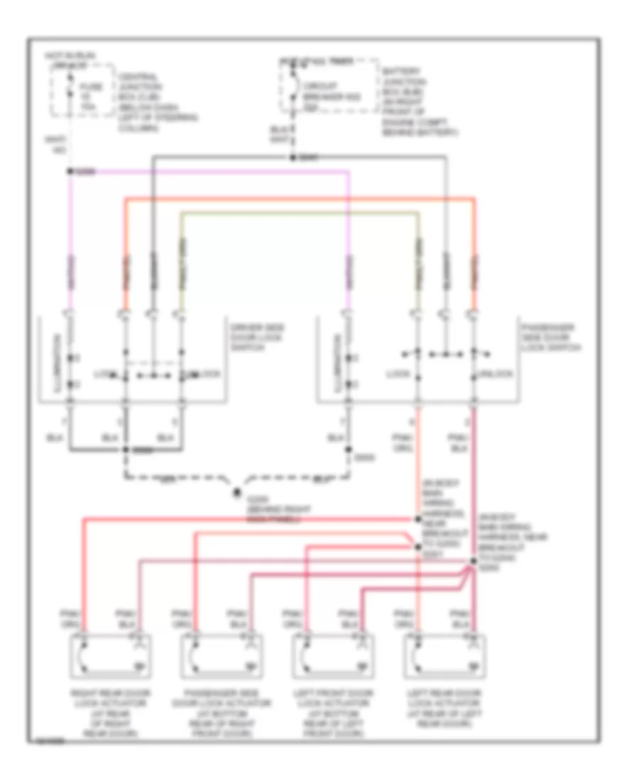
- Door locks system
- Driver door module (bottom front of left front door)
- Fuse 10a
- Fuse 15a
- Fuse 20a
- G200 (behind right kick panel)
- Hot at all times
- Hot in run
- Hot in start
- Hot with bpp switch engaged
- Instrument cluster
- Left front exterior door handle switch
- Lighting control module (behind center of dash)
- Right front exterior door handle switch
- S205
- S238 (in main body wiring harness, near breakout to c214)
- S258
- S274
- S277 (near breakout to lighting control module)
- S500
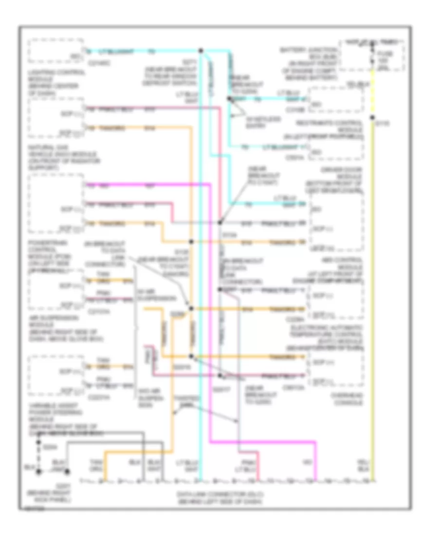
COMPUTER DATA LINES
Computer Data Lines Wiring Diagram for Mercury Grand Marquis GS 2004
List of elements for Computer Data Lines Wiring Diagram for Mercury Grand Marquis GS 2004:
- (in breakout to data link connector)
- (in breakout to data link connector) s297
- (near breakout to c1047)
- (near breakout to g200)
- (near breakout to g204) s241
- Abs control module (at left front of engine compartment)
- Air suspension module (behind right side of dash, above glove box)
- Battery junction box (bjb) (in right front of engine compt, behind battery)
- C2131a
- C2145c
- C2231a
- C228a
- C310b
- C501a
- C9013a
- Data link connector (dlc) (behind left side of dash)
- Driver door module (bottom front of left front door)
- Electronic automatic temperature control (eatc) module (behind center of dash
- Fuse 30a
- G201 (behind right kick panel)
- Hot at all times
- Iso
- Lighting control module (behind center of dash)
- Natural gas vehicle (ngv) module (on front of radiator support)
- Overhead console
- Powertrain control module (pcm) (on left side of firewall)
- Restraints control module (in left front footwell)
- S115
- S134
- S135 (near breakout to c1047)
- S2016
- S2017
- S204
- S271 (near breakout to rear window defrost switch)
- S296
- Scp (+)
- Scp (-)
- Twisted pair
- Variable assist power steering module (behind right side of dash, above glove box)
- W/ air suspension
- W/ keyless entry
- W/o air suspen- sion
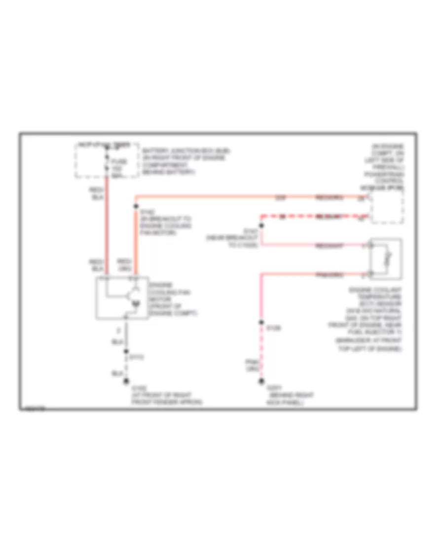
COOLING FAN
Cooling Fan Wiring Diagram for Mercury Grand Marquis GS 2004
List of elements for Cooling Fan Wiring Diagram for Mercury Grand Marquis GS 2004:
- (behind right
- (in engine compt, on left side of firewall) powertrain control module (pcm)
- (marauder: at front
- Battery junction box (bjb) (in right front of engine compartment, behind battery)
- Engine coolant temperature (ect) sensor (w/ & w/o natural gas: on top right front of engine, near fuel injector 1)
- Engine cooling fan motor (front of engine compt)
- Fuse 50a
- G102 (at front of right front fender apron)
- G201
- Hot at all times
- Kick panel)
- S113
- S128
- S141 (near breakout to c1026)
- S142 (in breakout to engine cooling fan motor)
- Top left of engine)
CRUISE CONTROL
Cruise Control Wiring Diagram for Mercury Grand Marquis GS 2004
List of elements for Cruise Control Wiring Diagram for Mercury Grand Marquis GS 2004:
- (in dash panel to headlamp junction harness, near breakout to speed control actuator) s129
- Air bag sliding contact (at base of steering column)
- Battery junction box (bjb) (in right front of engine compt, behind battery)
- Brake pedal position switch (top of brake pedal support)
- C2145a
- C218a
- C218c
- C220a
- Central junction box (cjb) (below dash, left of steering column)
- Coast
- Ctrl sw rtn
- Deactivator switch (in left front footwell)
- Digital
- Except steering wheel audio/climate control switch
- Fuse 15a
- Fuse 20a
- G201 (behind right kick panel)
- Ground
- Horn relay
- Horn switch
- Hot at all times
- Hot in acc or run
- Instrument cluster
- Interior lights system
- Lighting control module (behind center of dash)
- Nca
- Off
- Powertrain control module (pcm) (in engine compt, on left side of firewall)
- Red/pnk
- Resume
- S104
- S122
- S123 (in engine control sensor & fuel charge wiring harness, near breakout to c1033)
- S126 (in engine control sensor & fuel charge wiring harness, near breakout to coil on plug 4)
- S128
- S132 (in dash panel to headlamp junction harness, left rear of engine compt)
- S265
- Set/ accel
- Speed control actuator (left rear side of engine compt)
- Speed control ind
- Speed control switch
- Steering wheel audio/climate control switch
- Throttle position sensor (tps) (on left side of throttle body)
- Vpwr
- Vref
- W/ steering wheel controls
- W/o steering wheel controls
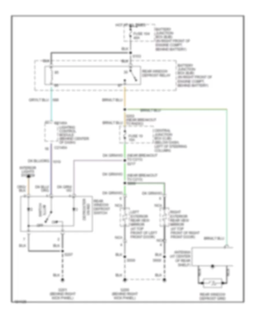
DEFOGGERS
Defoggers Wiring Diagram for Mercury Grand Marquis GS 2004
List of elements for Defoggers Wiring Diagram for Mercury Grand Marquis GS 2004:
- (near breakout to c213) s200
- Antenna (at center of rear shelf)
- Battery junction box (bjb) (in right front of engine compt, behind battery)
- C2145a
- Central junction box (cjb) (below dash, left of steering column)
- Fuse 10 10a
- Fuse 104 40a
- G200 (behind right kick panel)
- G201 (behind right kick panel)
- Hot at all times
- Illum switch
- Interior lights system
- Left exterior rear view mirror (at top front of left front door)
- Lighting control module (behind center of dash)
- Nca
- Off
- On ind defroster
- Rear window defrost grid
- Rear window defrost relay
- Rear window defrost switch
- Right exterior rear view mirror (at top front of right front door)
- S153
- S207
- S500
- S600
ELECTRONIC POWER STEERING
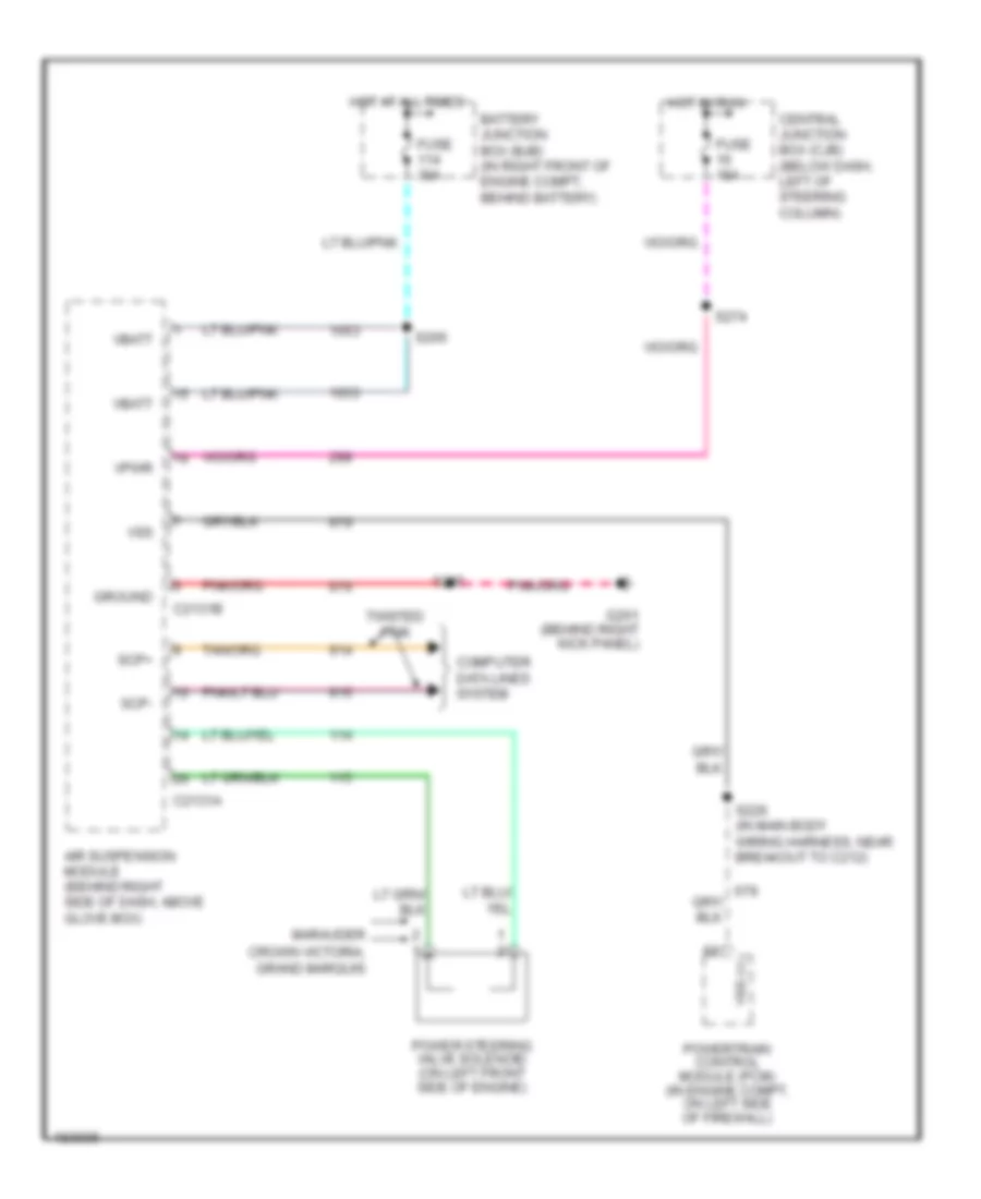
Electronic Power Steering Wiring Diagram, with Air Suspension for Mercury Grand Marquis GS 2004
List of elements for Electronic Power Steering Wiring Diagram, with Air Suspension for Mercury Grand Marquis GS 2004:
- Air suspension module (behind right side of dash, above glove box)
- Battery junction box (bjb) (in right front of engine compt, behind battery)
- C2131a
- C2131b
- Central junction box (cjb) (below dash, left of steering column)
- Computer data lines system
- Crown victoria, grand marquis
- Fuse 15a
- Fuse 30a
- G201 (behind right kick panel)
- Ground
- Hot at all times
- Hot in run
- Marauder
- Power steering valve solenoid (on left front side of engine)
- Powertrain control module (pcm) (in engine compt, on left side of firewall)
- S205
- S206
- S226 (in main body wiring harness, near breakout to c212)
- S274
- Scp+
- Scp-
- Twisted pair
- Vbatt
- Vpwr
- Vss
- Vss (+)
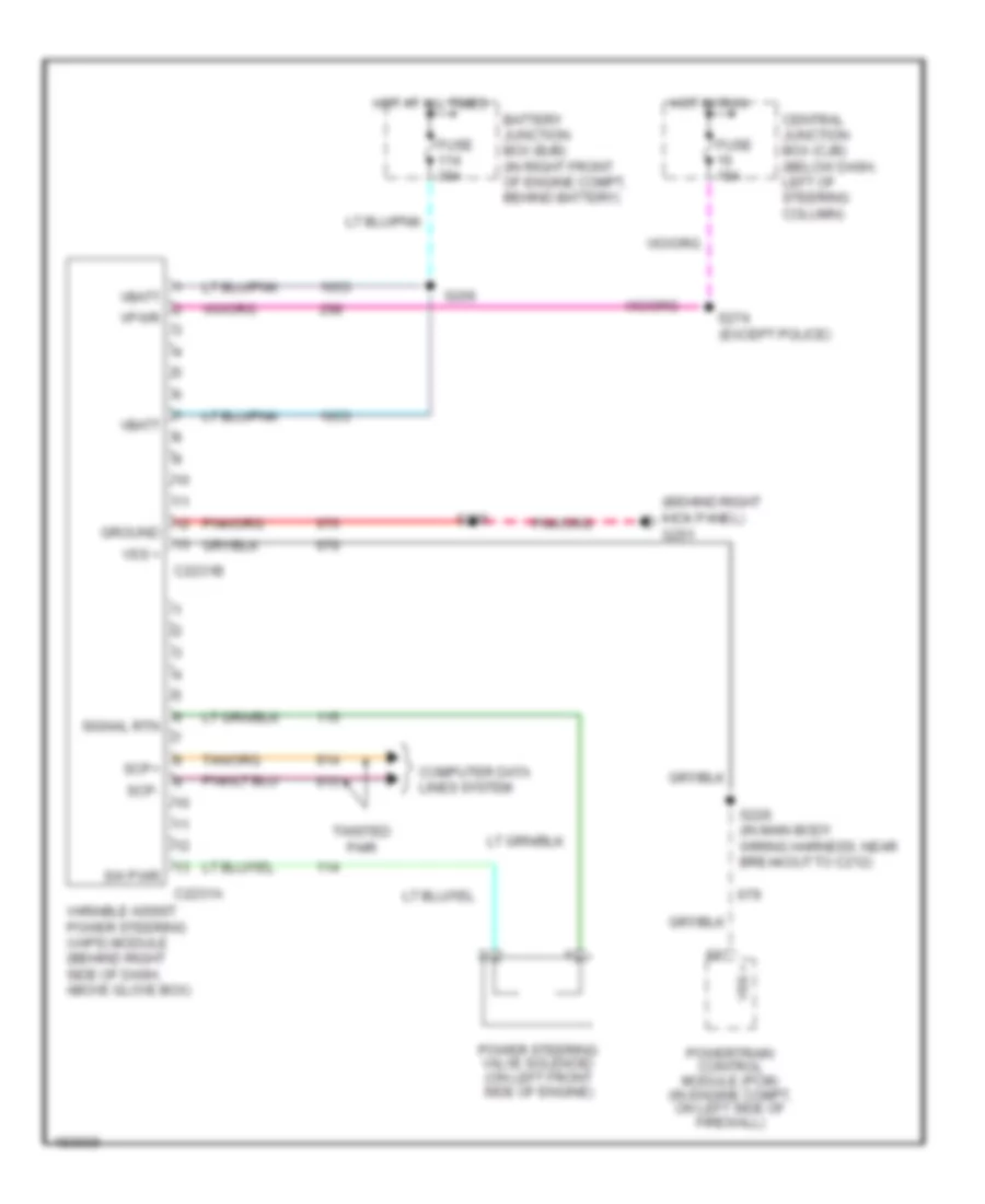
Electronic Power Steering Wiring Diagram, without Air Suspension for Mercury Grand Marquis GS 2004
List of elements for Electronic Power Steering Wiring Diagram, without Air Suspension for Mercury Grand Marquis GS 2004:
- (behind right kick panel) g201
- Battery junction box (bjb) (in right front of engine compt, behind battery)
- C2231a
- C2231b
- Central junction box (cjb) (below dash, left of steering column)
- Computer data lines system
- Fuse 15a
- Fuse 30a
- Ground
- Hot at all times
- Hot in run
- Power steering valve solenoid (on left front side of engine)
- Powertrain control module (pcm) (in engine compt, on left side of firewall)
- S205
- S206
- S226 (in main body wiring harness, near breakout to c212)
- S274 (except police)
- Scp+
- Scp-
- Signal rtn
- Sw pwr
- Twisted pair
- Variable assist power steering (vaps) module (behind right side of dash, above glove box)
- Vbatt
- Vpwr
- Vss +
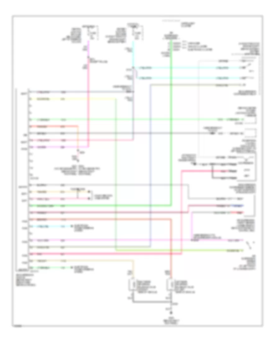
ELECTRONIC SUSPENSION
Electronic Suspension Wiring Diagram for Mercury Grand Marquis GS 2004
List of elements for Electronic Suspension Wiring Diagram for Mercury Grand Marquis GS 2004:
- (at front of right front fender apron) g102
- (behind center of dash) lighting control module
- (in right front of engine compt, behind battery) battery junction box
- (near breakout to air suspension module) s246
- (near breakout to c212) s226
- (near breakout to c214) s206
- (w/o keyless entry) (behind right kick panel)
- Air suspension compressor assembly (at left side front of engine compt)
- Air suspension compressor relay
- Air suspension disable switch (at left front of luggage compt)
- Air suspension height sensor (under rear of vehicle attached to control arm)
- Air suspension indicator
- Air suspension module (behind right side of dash, above glove box)
- Analog cluster
- Battery junction box (bjb) (in right front of engine compt, behind battery)
- C2131a
- C2131b
- C2145c
- C220a
- C2220a
- Central junction box (cjb) (below dash, left of steering column)
- Compressor
- Computer data lines system
- Electronic cluster
- Electronic power steering system
- Fuse 15a
- Fuse 30a
- G200 (behind right kick panel)
- G201 g202 (w/ keyless entry) (behind right kick panel)
- Hot at all times
- Hot in run
- Instrument cluster
- Left rear air spring solenoid valve (at left rear of vehicle)
- Marauder
- Nca
- Pnk
- Powertrain control module (pcm) (in engine compt, on left side of firewall)
- Pwr
- Red
- Right rear air spring solenoid valve (at right rear of vehicle)
- S100
- S112
- S205
- S274 (except police)
- S406
- Scp+
- Scp-
- Sig rtn
- Twisted pair
- Vbatt
- Vent
- Vpwr
- Vss
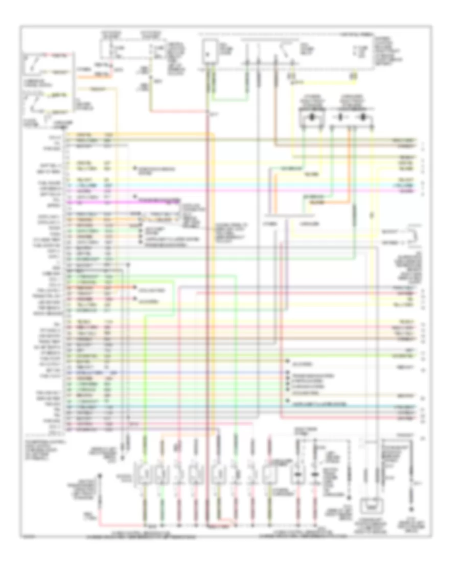
ENGINE PERFORMANCE
4.6L
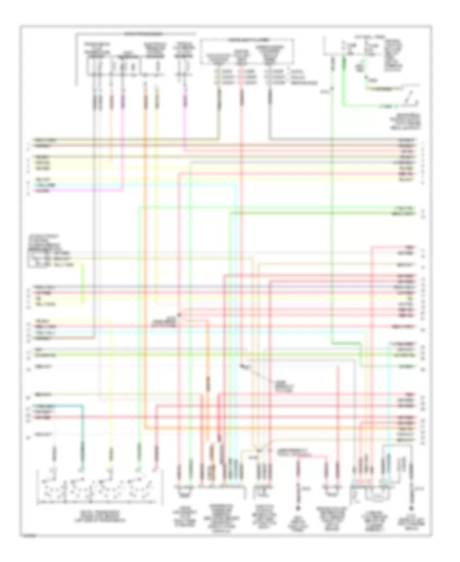
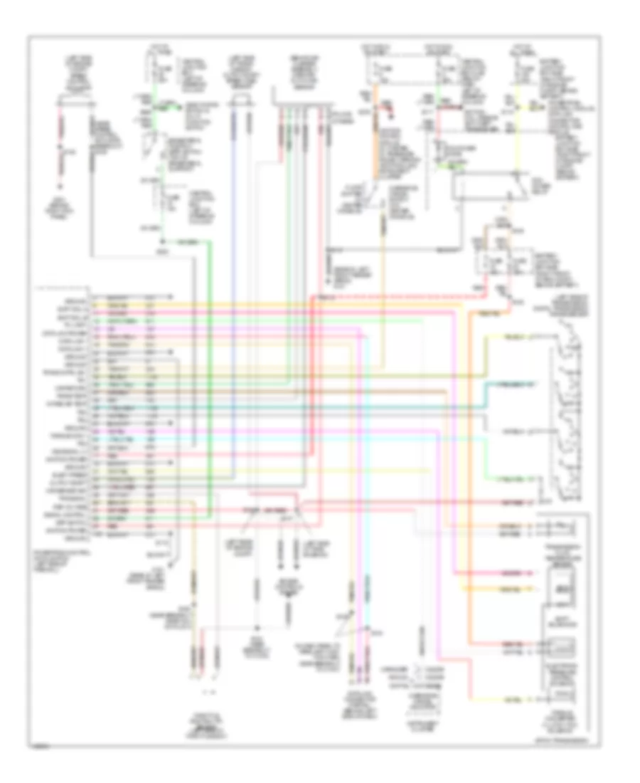
4.6L, Engine Performance Wiring Diagram (1 of 4) for Mercury Grand Marquis GS 2004
List of elements for 4.6L, Engine Performance Wiring Diagram (1 of 4) for Mercury Grand Marquis GS 2004:
- (-)
- (in dash panel to headlamp junc- tion harn, near breakout to c1047)
- (in eng control sensor & fuel charge wiring harn, near breakout at left rear of eng)
- (in eng control sensor & fuel charge wiring harn, near breakout to c1033)
- (left center of eng)
- (marauder)
- (marauder) (others)
- (others)
- (others) (marauder)
- (rear of left front fender apron) g101
- (right front of engine) knock sensor
- (right rear of eng)
- A/c air temp in
- A/c cutout
- A/c evaporator discharge air temperature sensor (right side rear of eng compt)
- A/c system
- Anti-theft system
- Battery junction box (bjb) (right front of engine compt, behind battery)
- Case gnd
- Central junction box (cjb) (below dash, left of steering column)
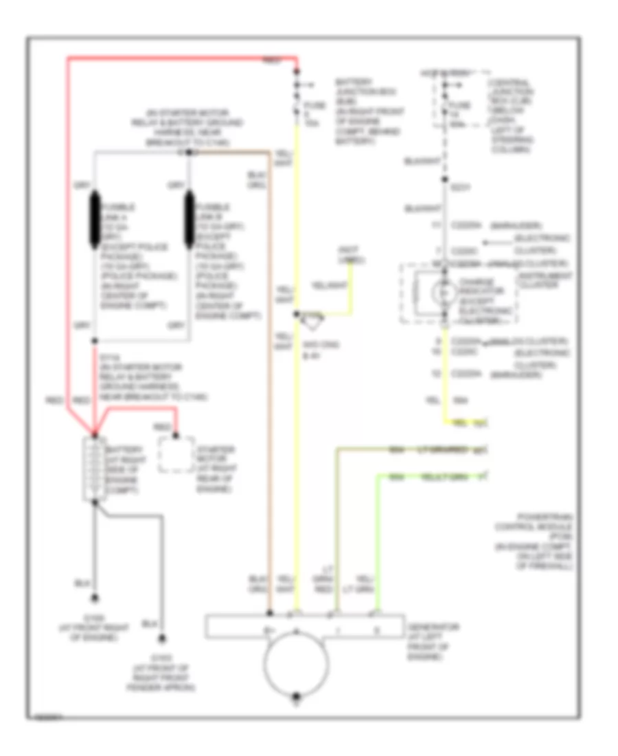
- Charging system
- Ckp (+)
- Ckp (-)
- Coil 1
- Coil 3
- Coil 4
- Coil 5
- Coil 6
- Cooling fans
- Crankshaft position sensor (lower right front of engine)
- Crankshaft position sensor shield
- Cyl head temp
- Data link (+)
- Data link (-)
- Data link connector (dlc) (behind left side of dash)
- Ect ind
- Egr vac reg
- Eprom
- Fan high rly
- Fan low rly
- Floor shifter
- Fuel door ind
- Fuel flow
- Fuel gauge
- Fuel pump
- Fuse 15a
- Fuse 25a
- Fuse 30a
- G101 (rear of left front fender apron)
- Gen "s" term
- Gnd
- Hot at all times
- Hot in run or start
- Iat sens in
- Ignition coils
- Ignition trans- former capa- citor 1&2 (marauder)
- Ignition transformer capacitor (left front of engine)
- Instrument cluster system
- Knock sens sig
- Led sig gnd
- Maf sig rtn
- Map sens in
- Marauder
- Marauder others
- Mil
- Nca
- Others
- Overdrive cancel switch
- Pcm power diode
- Pcm power relay
- Powertrain control module (pcm) (in engine compt, on left side of firewall)
- Psp sens in
- Pwr gnd
- Rt ho2s 12
- Rx sig
- S101
- S103
- S111
- S115
- S117
- S118
- S134
- S135
- S140
- S151
- S160
- S223
- S276
- Shft sol a
- Shft sol b
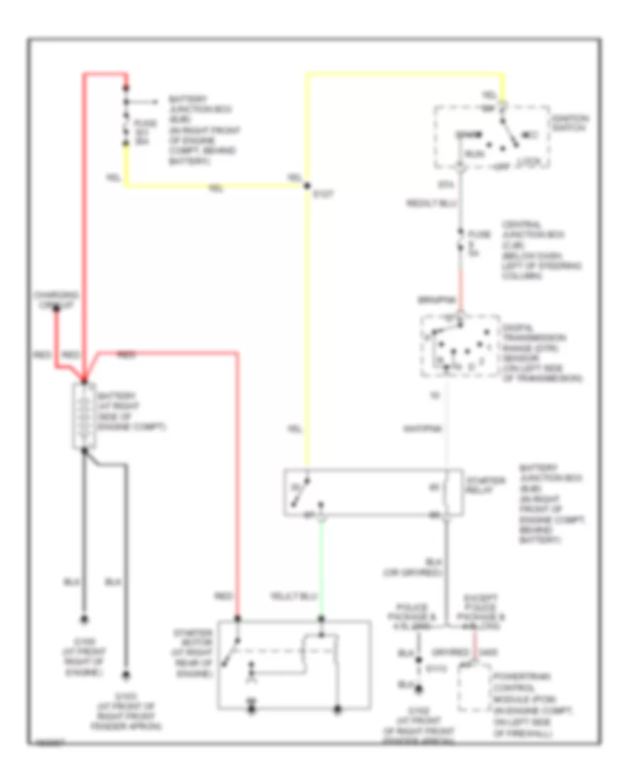
- Starting system
- Starting/charging system
- Tach sig
- Tcil
- Tr1
- Tr2
- Tr4
- Trans ctrl sw
- Trans temp
- Transmissions system
- Tx sig
- W/ center console
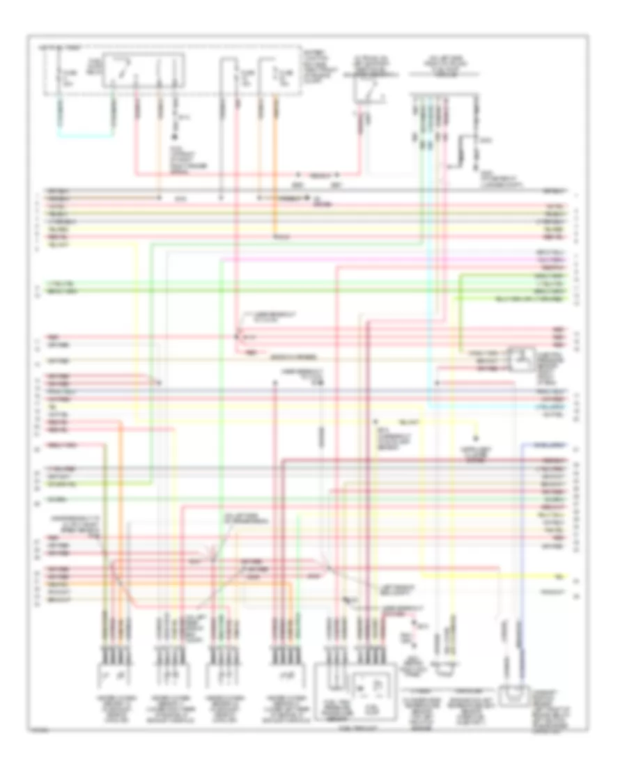
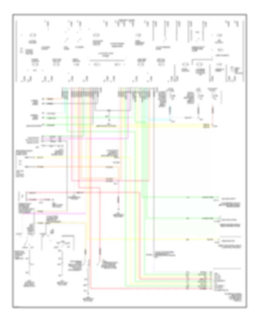
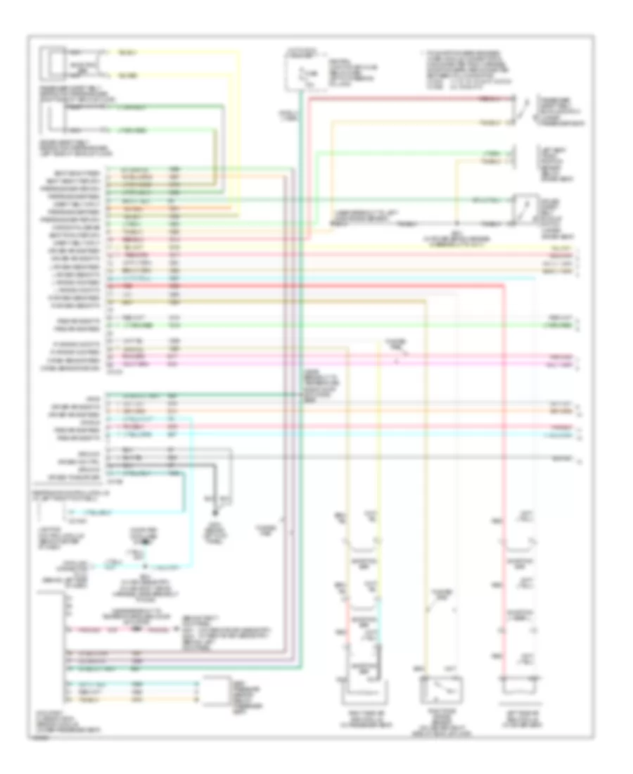
4.6L, Engine Performance Wiring Diagram (2 of 4) for Mercury Grand Marquis GS 2004
List of elements for 4.6L, Engine Performance Wiring Diagram (2 of 4) for Mercury Grand Marquis GS 2004:
- (at right front of engine)
- (near break- out to c1033)
- (near breakout to c1026)
- (near breakout to coil on plug 4)
- (speedometer/ odometer) vehicle speed input
- 4r70w transmission
- Analog
- Brake pedal position switch (top of brake pedal support)
- C220b
- C220c
- C2220a
- C2220b
- Central junction box (cjb) (below dash, left of steering column)
- Differential pressure feedback egr (dpfe) sensor (near right side of intake manifold)
- Digital
- Digital transmission range (dtr) sensor (left side of transmission)
- Electronic pressure control solenoid
- Engine coolant temp input
- Engine coolant temperature (ect) sensor (front top left of engine)
- Fuse 15a
- G101 (rear of left front fender apron)
- G201 (behind right kick panel)
- Hot at all times
- Instrument cluster
- Malfunction indicator input
- Mass air- flow sensor (behind air cleaner assembly)
- Others
- Performance
- Police
- Power steering pressure switch
- R n
- Red
- Red marauder
- S118
- S126
- S128
- S132
- S141
- S150
- S265
- Shift solenoids
- Ssa
- Ssb
- Throttle position sensor (tps) (left side of throttle body)
- Torque converter clutch solenoid
- Transmission fluid temperature sensor
- Vapor management valve (right rear of engine)
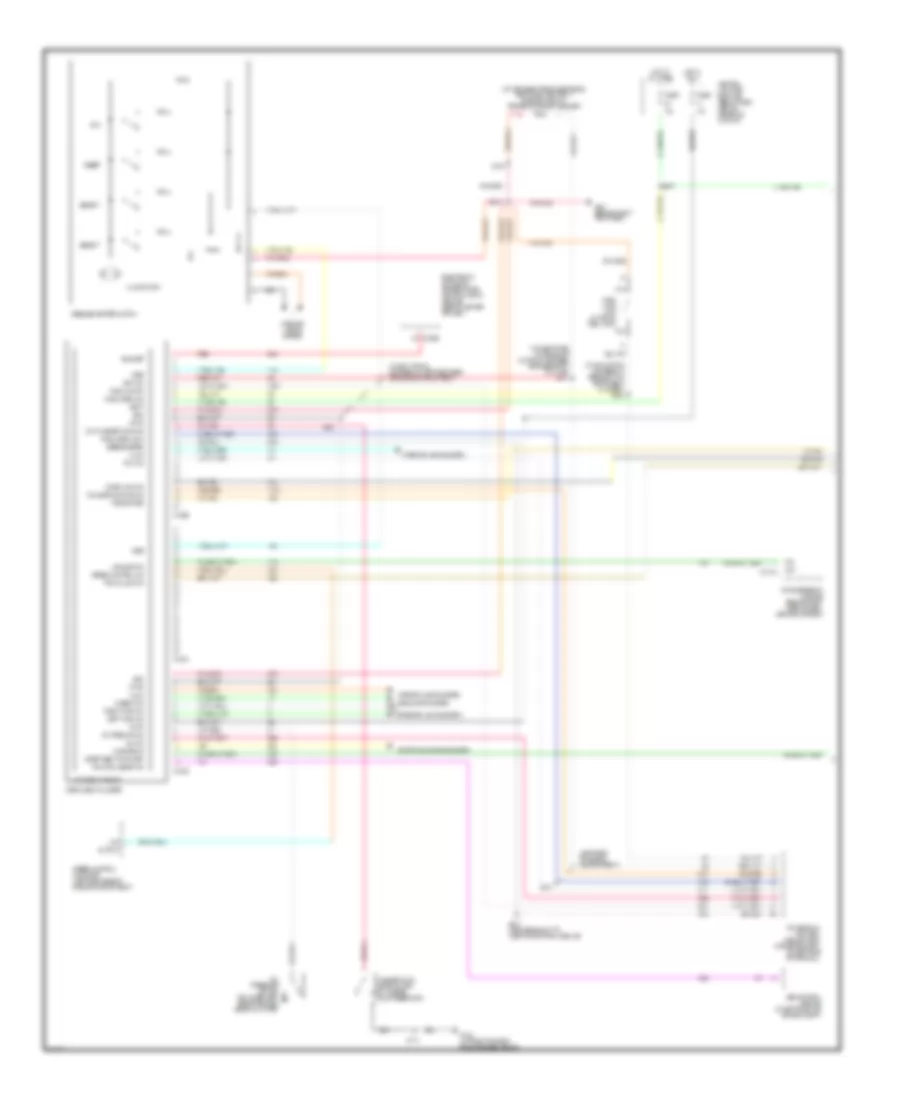
4.6L, Engine Performance Wiring Diagram (3 of 4) for Mercury Grand Marquis GS 2004
List of elements for 4.6L, Engine Performance Wiring Diagram (3 of 4) for Mercury Grand Marquis GS 2004:
- (ends in harness)
- (in trunk, on left support) inertia fuel shut-off (ifs) switch
- (left rear of eng compt)
- (near breakout to c1019)
- (near breakout to c1026)
- (near breakout to c1033 s123
- (near breakout to output shaft speed sensor) s146
- (on left side front of trunk) fuel pump module
- (on left side of transmission)
- A/c system
- Battery junction box (bjb) (right front of engine compt)
- Camshaft position sensor (left front of engine, below left ignition transformer capacitor)
- Cylinder-head temperature sensor (top left front of engine)
- Engine coolant temperature (ect) sensor (near fuel injector 1)
- Fuel pump
- Fuel pump relay
- Fuel tank pressure transducer sensor
- Fuel tank unit
- Fuse 15a
- Fuse 20a
- G102 (at front of right front fender apron)
- G201 (behind right kick panel)
- G400 (at center of luggage compt)
- Heated oxygen sensor 11 (lower right rear of engine, in exhaust manifold)
- Heated oxygen sensor 12 (in exhaust, rear of catalyst)
- Heated oxygen sensor 21 (lower left rear of engine, in exhaust manifold)
- Heated oxygen sensor 22 (in exhaust, rear of catalyst)
- Hot at all times
- Injection pressure sensor (right front of eng)
- Instrument cluster system
- Marauder
- Nca
- Others
- Red
- Red/pnk
- S109
- S110
- S113
- S125
- S130
- S143
- S147
- S210
- S210 (in breakout to autolamp sensor)
- S256
- S267
- S286
- S303
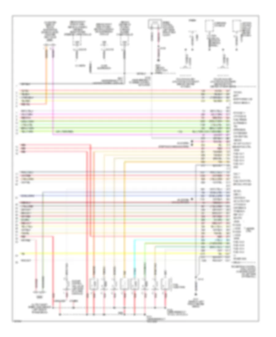
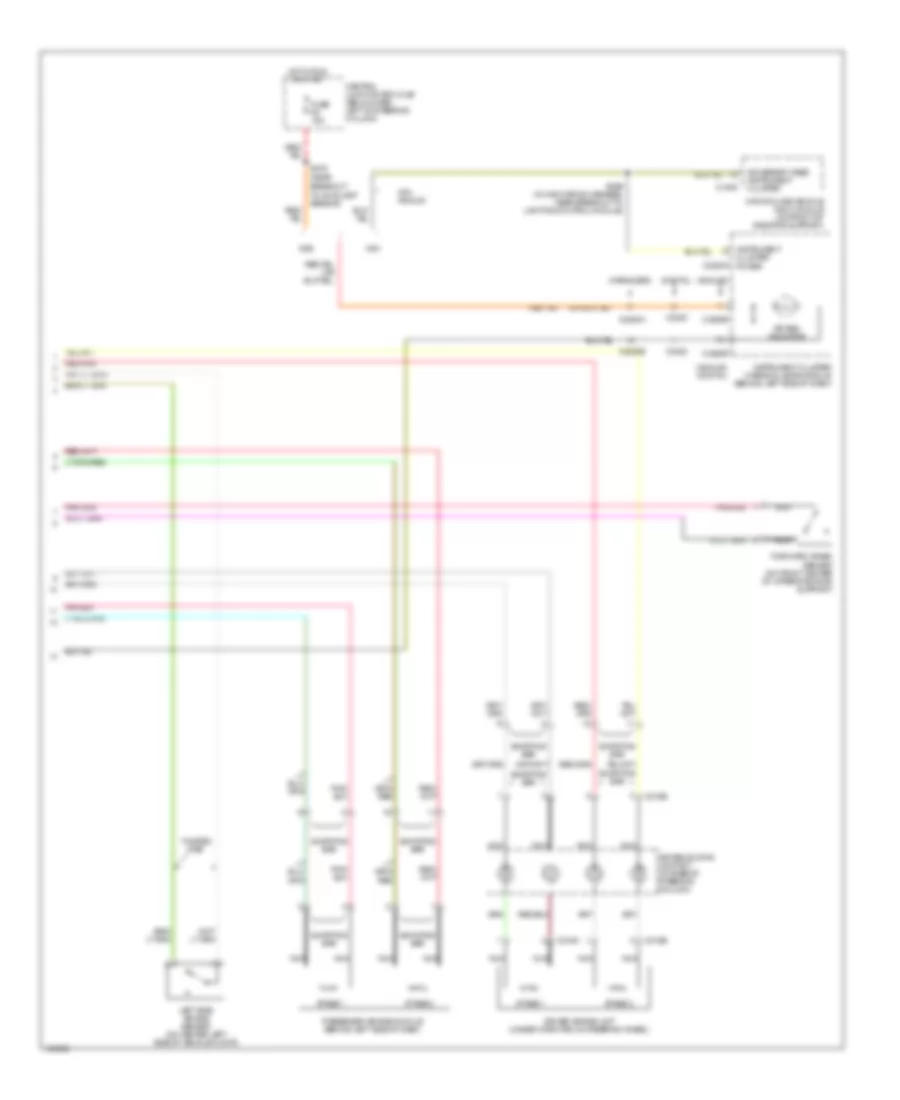
4.6L, Engine Performance Wiring Diagram (4 of 4) for Mercury Grand Marquis GS 2004
List of elements for 4.6L, Engine Performance Wiring Diagram (4 of 4) for Mercury Grand Marquis GS 2004:
- (+)
- (behind center of of dash) warning buzzer/ chime module
- (behind right side of dash, above glove box) air suspension module
- (behind right side of dash, above glove box) variable assist power steering (vaps) module
- (in center rear of trunk) evaporative emission (evap) canister vent valve
- A/c cutout sw
- A/c system
- A/c system (a/c clutch sw)
- A/c wot cutout
- Batt
- C2131b
- C2145b
- C2231b
- C2232b
- C290c
- C4170d
- C9013a (w/ roof opening panel)
- Cam pos in
- Can vent sol
- Cht sensor
- Coil 2
- Coil 7
- Coil 8
- Compt)
- Dpfe sens
- Epc sol rtn sig
- Evap purge vlve
- Fuel inj 1
- Fuel inj 2
- Fuel inj 3
- Fuel inj 4
- Fuel inj 5
- Fuel inj 6
- Fuel inj 7
- Fuel inj 8
- Fuel injectors
- Fuel press
- Fuel pump ctrl
- G101 (rear of left front fender apron)
- G201 (behind right kick panel)
- Gen/bat ind ctrl
- Gnd
- Heater ctrl
- Iac sol
- Idle air control (iac) valve (left side of intake manifold)
- Inj press in
- Knock sens (+)
- L ho2s
- Lft ho2s 21
- Lft ho2s 22
- Lighting control module (behind center of dash)
- Maf sens in
- Marauder
- Oss (+)
- Others
- Output shaft speed (oss) sensor (left side of transmission)
- Overhead console
- Police auxiliary junction block (front) (behind center of dash)
- Police auxiliary junction block (rear) (behind bottom center of rear seats)
- Power gnd
- Powertrain control module (pcm) (in engine compt, on left side of firewall)
- R ho2s
- Radio
- Red
- Red/pnk
- Ref volt
- Rt ho2s 11
- S118
- S128
- S129 (near breakout to speed control actuator)
- S131 (near breakout to c1033)
- S148 (near breakout to coil on plug 4)
- S247 (near breakout to lighting control module)
- Sig rtn
- Speed control actuator (left rear side of eng
- Starting/charging system
- Tan
- Tan/red
- Tcc sol
- Tp sens in
- Tr3
- Vpwr
- Vss (+)
- Vss sig
- W/ air suspension
- W/ varps
EXTERIOR LIGHTS
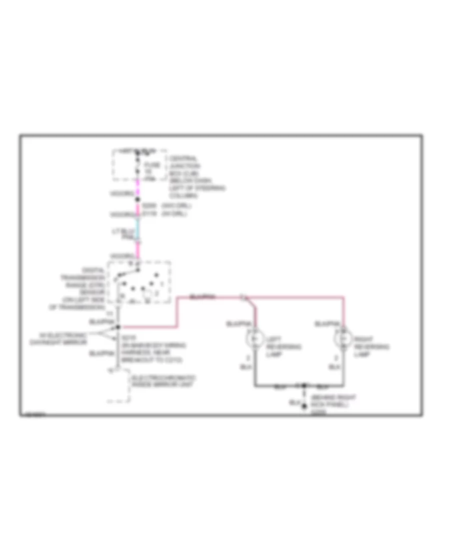
Back-up Lamps Wiring Diagram for Mercury Grand Marquis GS 2004
List of elements for Back-up Lamps Wiring Diagram for Mercury Grand Marquis GS 2004:
- (behind right kick panel) g200
- (w/o drl) (w/ drl)
- Breakout to c213)
- Central junction box (cjb) (below dash, left of steering column)
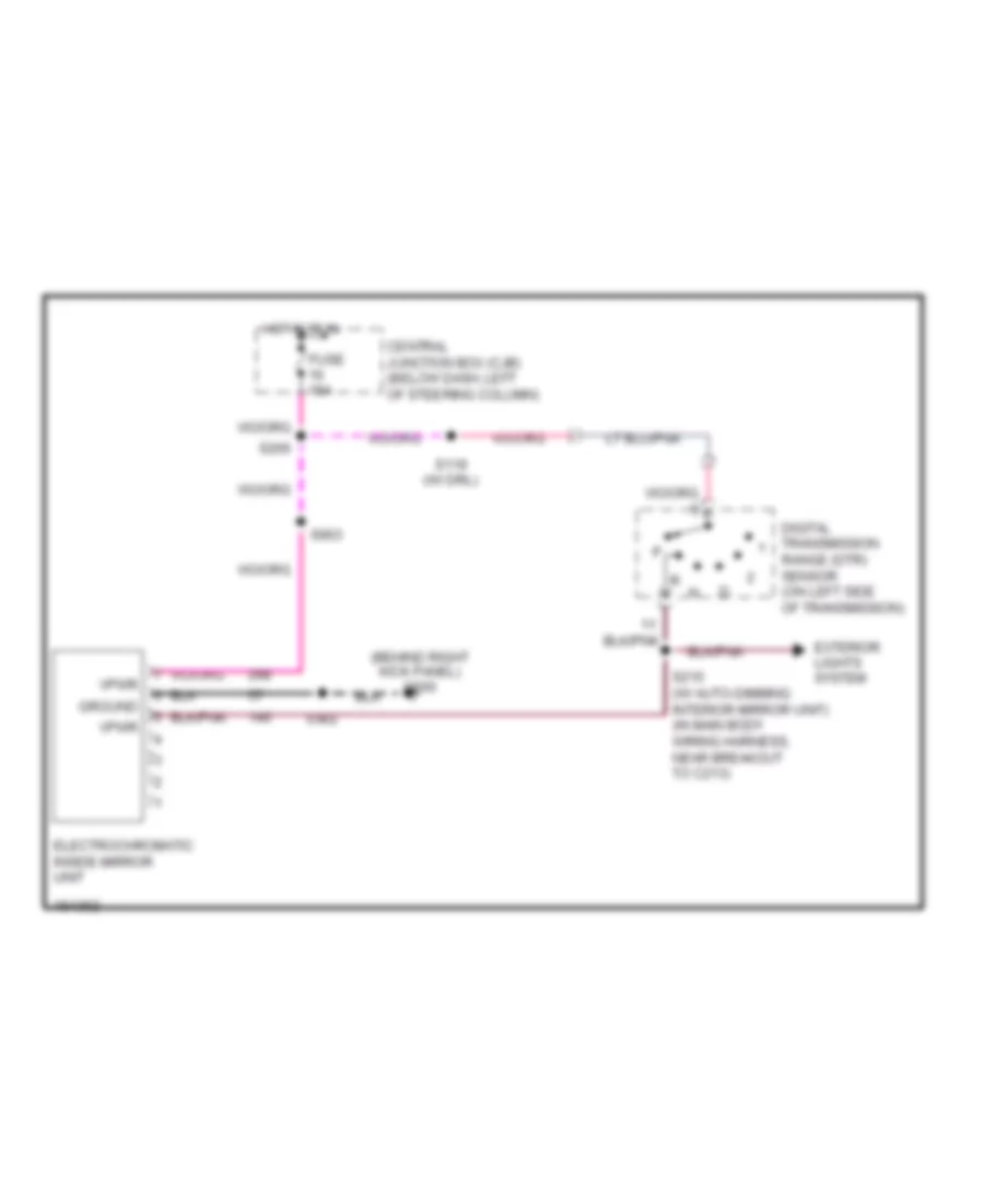
- Digital transmission range (dtr) sensor (on left side of transmission)
- Electrochromatic inside mirror unit
- Fuse 15a
- Hot in run
- Left reversing lamp
- Right reversing lamp
- S420
- W/ electronic day/night mirror
Exterior Lamps Wiring Diagram for Mercury Grand Marquis GS 2004
List of elements for Exterior Lamps Wiring Diagram for Mercury Grand Marquis GS 2004:
- (at front of right front fender apron) g102
- (behind center of dash) lighting control module
- (behind right kick panel)
- (behind right kick panel) g200
- (in breakout to c410)
- (in breakout to c410) s413
- (in dash panel to headlamp junction harness, near breakout to c1019)
- (in main wiring harness, in breakout to instrument cluster)
- (in main wiring harness, near breakout to lighting control module) s244
- (in rear lamp wiring harness, in breakout to c411)
- (in rear lamp wiring harness, in breakout to c411) s414
- (near breakout to g400) s409
- (near breakout to c1010) s116
- (near breakout to c213) s283
- (near breakout to left front brake sensor) s120
- (near breakout to lighting control module)
- (no connection)
- (on steering column)
- Accessory circuit
- Analog
- Auto
- Autolamp on/off signal
- Brake pedal position switch (top of brake pedal support)
- Breakout to g204) s258
- C202a
- C202c
- C205a
- C2145a
- C2145b
- C2145c
- C220c
- C2220a
- C2220b
- C501a
- Central junction box (cjb) (below dash, left of steering column)
- Digital
- Driver door module (bottom front of left front door)
- Ends in harness
- Flasher power input
- Flasher power output
- Fuse 15a
- Fuse 20a
- Fuse 25a
- G102 (at front of right front fender apron)
- G201
- G400 (at center of luggage compartment)
- G401 (at center of package tray)
- Hazard
- Head
- Headlamps, off, monitor
- Headlamps, on/off signal
- Headlights system (marauder)
- High mounted stoplamp
- Hot at all times
- Hot in run
- Instrument cluster
- Left front park/ turn lamp
- Left front parking lamp
- Left rear park/stop/ turn lamp 1
- Left rear park/stop/ turn lamp 2
- Left turn
- Left turn ind
- License lamp
- Lo beams output
- Main light
- Multi- function switch
- Nca
- Normal
- Off
- Park
- Park lamps, on/off signal
- Parklamp output
- Performance
- Right front park/ turn lamp
- Right front parking lamp
- Right rear park/stop/ turn lamp 1
- Right rear park/stop/ turn lamp 2
- Right turn
- Right turn ind
- S107
- S108
- S113
- S207
- S242 (in main wiring harness, near breakout to ignition switch)
- S257
- S262
- S263
- S265
- S273 (police) (near breakout to lighting control module)
- S281
- S282
- S285
- S400
- S401
- S416
- S420
- S422
- S442
- Shift interlock, cruise control, anti-lock brakes, engine controls systems
- Switch
- Taxi
- Taxi roof lamp
- Taxi roof lamp switch
- Turn left
- Turn right
- Vbatt
- W/ keyless entry
GROUND DISTRIBUTION
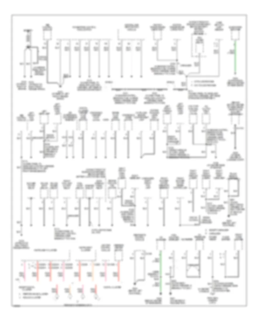
Ground Distribution Wiring Diagram (1 of 3) for Mercury Grand Marquis GS 2004
List of elements for Ground Distribution Wiring Diagram (1 of 3) for Mercury Grand Marquis GS 2004:
- (4.6l cng)
- (at front right of engine)
- (behind bottom center of rear seats) rear police auxiliary junction box
- (digital cluster) washer fluid level switch
- (in right front of engine compartment, behind battery) battery junction box (bjb)
- (marauder) right front fog lamp
- (near breakout to c410) s446
- (w/ police) engine compartment lamp
- 4.6l
- A/c clutch field coil
- Abs control module
- Air suspension compressor assembly
- Analog cluster
- Battery
- Blower motor relay
- Body wiring harness, at right center of vehicle floor)
- Brake fluid level switch
- C2145b
- C220b
- C220c
- C2220a
- C2220b
- C310b
- C4170c
- Cd changer
- Crown police
- Crown victoria
- Daytime running lamps (drl) module
- Digital cluster
- Engine cooling fan motor
- Except digital cluster
- Except marauder
- Floor shifter
- From s204 (diagram 2 of 3)
- From s210 (diagram 2 of 3)
- Front blower motor resistor assembly
- Front blower motor speed controller
- Front cigar lighter
- Front fog lamp cutoff relay
- Fuel pump relay
- Fuel rail cutoff valve
- G100 g103 (at front of right front fender apron)
- G101 (at rear of left front fender apron)
- G102 (at front of right front fender apron)
- G106 (at center rear of engine)
- G202 (behind left kick panel)
- G204 (behind left kick panel)
- G401 (at center of package tray)
- G402 (behind center of rear seats)
- G404 (alpine radio) (behind center of rear seats)
- G405 (at rear center of luggage compt)
- Grand marquis/ marauder
- High mounted stoplamp
- Horn
- Ignition transformer capacitor 1
- Ignition transformer capacitor 2
- Instrument cluster
- Left front fog lamp
- Left front park/ turn lamp
- Left front parking lamp
- Left headlamp
- Lighting control module
- Low brand radio trunk ends in harness
- Marauder
- Mass air flow (maf) sensor
- Message center switch
- Natural gas vehicle (ngv) module
- Nca
- Oil pressure gauge
- Pcm power relay
- Performance cluster
- Police power relay
- Police stop relay
- Power point
- Powertrain control module (pcm)
- Restraints control module
- Right front park/ turn lamp
- Right front parking lamp
- Right headlamp
- Roof opening panel relay
- S101 (in engine control sensor & fuel charge wiring harness, near breakout to c1026)
- S107 (in turn lamps wiring harness, in breakout to c1019)
- S108 (grand marquis) (in turn lamps wiring harness, in breakout to c1010)
- S111 (in dash panel to headlamp junction harness, left rear of engine compartment)
- S113 (in dash panel to headlamp junction harness, near breakout to c1046)
- S118 (in dash panel to headlamp junction harness, left rear of engine compartment)
- S140 (in dash panel to headlamp junction harness, near breakout to c1026)
- S158 (in headlamp lead wiring harness, in breakout to c1046)
- S160 (in engine control sensor & fuel charge wiring harness, near breakout to c1026)
- S422 (in main body nca
- Shield
- Starter relay
- Subwoofer amplifier
- Trunk ends in harness
- Voltmeter
- W/ center console
- W/ police package
- W/ police package, 4.6l cng
- W/o police package
- Windshield washer pump motor
- Windshield wiper motor
- Wiring harness, in breakout to g401)
- Wiring harness, near breakout to floor shifter)
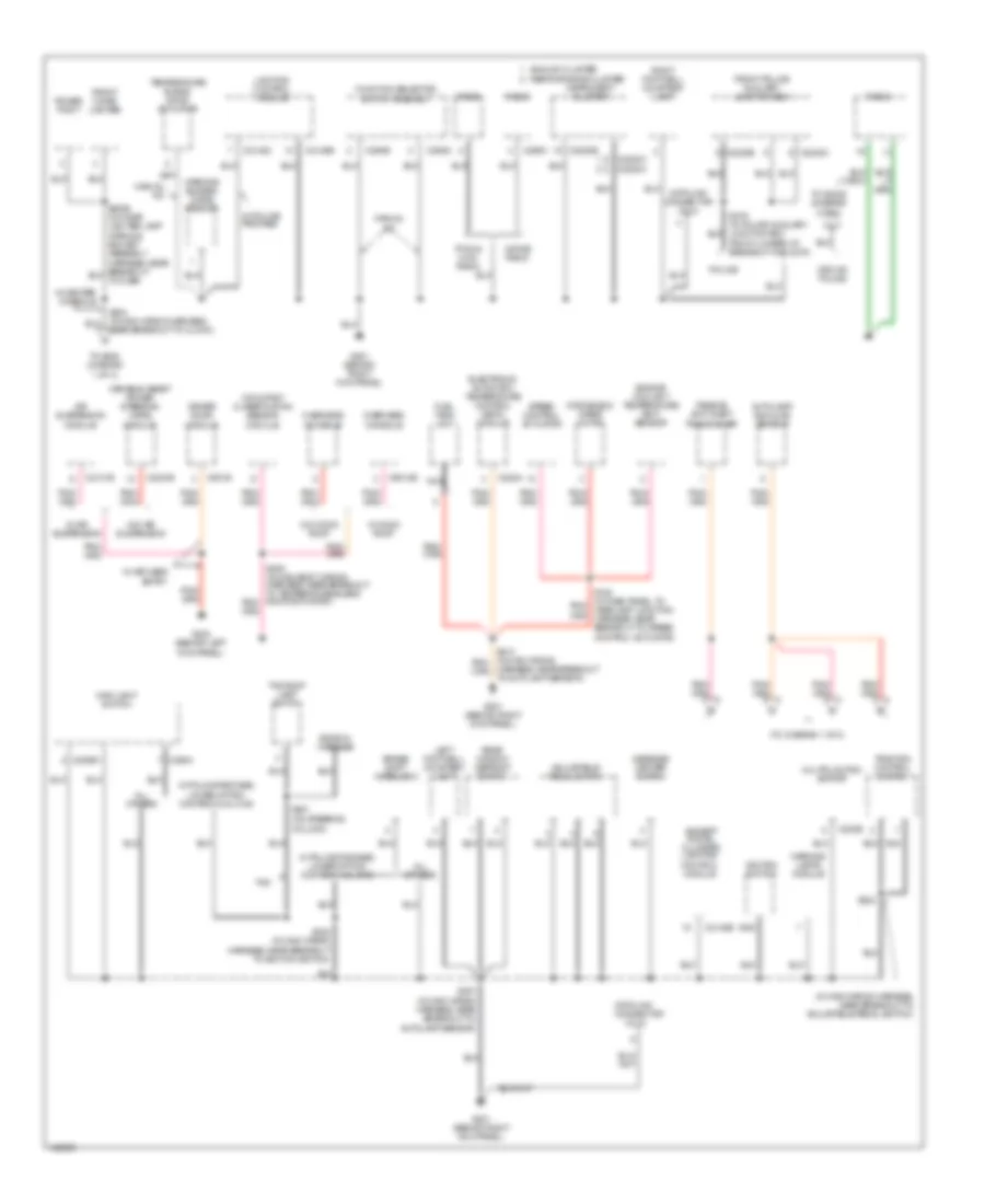
Ground Distribution Wiring Diagram (2 of 3) for Mercury Grand Marquis GS 2004
List of elements for Ground Distribution Wiring Diagram (2 of 3) for Mercury Grand Marquis GS 2004:
- (dlc)
- (except digital cluster) lighting control module
- (in main wiring harness, near breakout to adjustable pedal switch)
- (to diagram 1 of 3)
- 1 of 3)
- 3 of 3)
- Adjustable pedal switch
- Air suspension module
- All others
- Alpine radio
- Analog cluster
- Autolamp/ sunload sensor
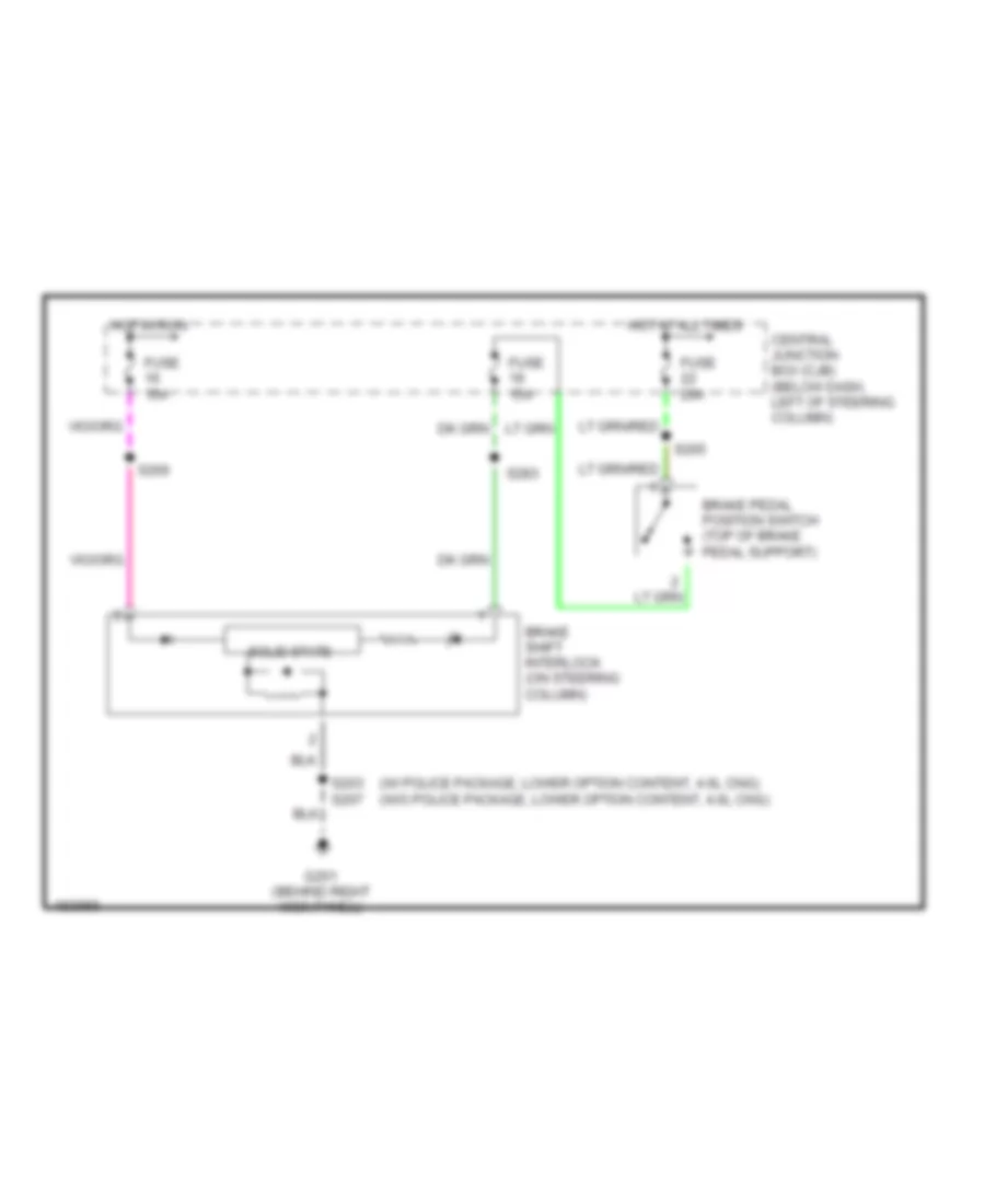
- Brake shift interlock
- C202b
- C205a
- C205b
- C2131b
- C2145b
- C2145c
- C2220a
- C2220b
- C2231b
- C2232b
- C2232c
- C228a
- C290c
- C294b
- C294d
- C501b
- C9013b
- Column)
- Crown police
- Data link connector
- Data link connector (dlc)
- Driver door module
- Electronic automatic temperature control (eatc) module
- Ends in harness
- Engine coolant temperature (ect) sensor
- Entry
- Front cigar lighter
- Front police auxiliary junction box
- Fuel tank unit
- Function selector switch assembly
- G201 (behind right kick panel)
- G202 (behind left kick panel)
- Gnd
- Harness, near breakout to autolamp sensor)
- Ignition switch
- Instrument cluster
- Left footwell courtesy lamp
- Lighting control module
- Main light switch
- Manual a/c
- Message center switch
- Multifunction switch
- Nca
- Near breakout to clock)
- Occupant classification sensor module
- Overhead console
- P100i & m100 radio
- Passive anti-theft transceiver
- Performance cluster
- Police
- Power point
- Radio
- Rear window defrost switch
- Right footwell courtesy lamp
- S203 (in main wiring harness, near breakout to ignition switch)
- S207 (in main wiring harness, near breakout to autolamp sensor)
- S224
- S279 (in police auxiliary junction box front jumper, at breakout for c275)
- S281 (on steering
- Speed control actuator
- Taxi
- Taxi roof lamp switch
- Temperature blend door actuator
- To s2025 (diagram
- To s248 (diagram
- Traction control switch
- Variable assist power steering (vaps) module
- W/ air suspension
- W/ center console
- W/ keyless
- W/ moon roof
- W/ police package
- W/ police package, lower option content, 4.6l cng
- W/o air suspension
- W/o moon roof
- Warning buzzer/ chime module
- Warning lamps module
- Windshield wiper motor
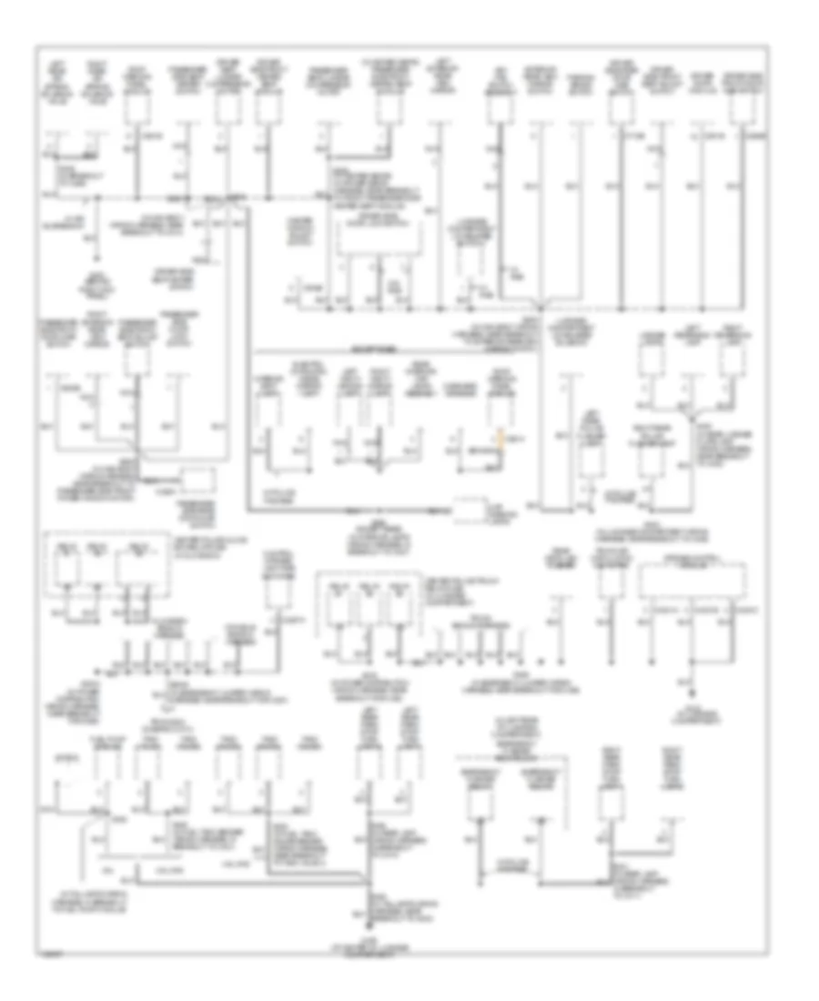
Ground Distribution Wiring Diagram (3 of 3) for Mercury Grand Marquis GS 2004
List of elements for Ground Distribution Wiring Diagram (3 of 3) for Mercury Grand Marquis GS 2004:
- (except base)
- (in interior lamps wiring harness, in breakout to c327)
- (in left rear of luggage compartment)
- (in main body wiring harness, near breakout to c214)
- (in taillamps wiring harness, in breakout to fuel pump module)
- (w/ heated seats) passenger side front heated seat module
- 4.6l
- 4.6l cng
- C3257a
- C4231a
- C4231b
- C4231c
- C501b
- C504b
- C526b
- C602b
- C715b
- C820a
- C921a
- C921b
- Center police glove box relay/fuse (in glove box)
- Center police trunk relay/fuse (in luggage compartment)
- Console ends in harness
- Control strobe/ light bar switches
- Driver door module
- Driver seat lumbar compressor motor
- Driver side door lock switch
- Driver side front door ajar switch
- Driver side front heated seat module
- Driver side front seat adjust switch
- Driver side rear door ajar switch
- Driver side seat heater switch
- Electro- chromatic inside mirror unit
- Emergency flasher relay 1
- Emergency flasher relay 2
- Emergency flasher relay block
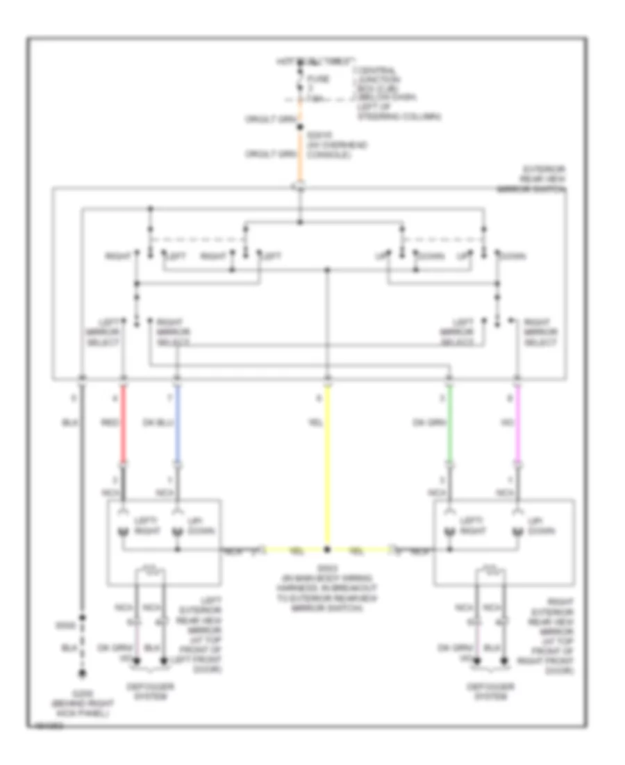
- Exterior rear view mirror switch
- From s204 (diagram 2 of 3)
- Fuel pump module
- G200 (behind right kick panel)
- G400 (at center of luggage compartment)
- G410 (in luggage compartment)
- Glove box ends in harness
- Interior spot lamp
- Key pad switch assembly
- Left exterior rear view mirror
- Left rear air spring solenoid valve
- Left rear park/ stop/ turn lamp 1
- Left rear park/ stop/ turn lamp 2
- Left rear police flasher lamp
- Left reversing lamp
- Left vanity mirror lamp
- License lamps
- Luggage compartment lid release solenoid
- Luggage compartment lid release switch 1
- Map reading lamps
- Master window adjust switch
- Nca
- Overhead console
- Parking brake switch
- Passenger seat lumbar compressor motor
- Passenger side door lock switch
- Passenger side front door ajar switch
- Passenger side front seat adjust switch
- Passenger side rear door ajar switch
- Passenger side seat heater switch
- Rear deck led flasher
- Rear interior/ map lamps assembly
- Relay a1
- Relay a4
- Relay a6
- Relay b1
- Relay b3
- Relay b4
- Right exterior rear view mirror
- Right rear air spring solenoid valve
- Right rear park/ stop/ turn lamp 1
- Right rear park/ stop/ turn lamp 2
- Right rear police flasher lamp
- Right reversing lamp
- Right vanity mirror lamp
- Roof opening panel module
- S2034 (in power distribution wiring harness, near breakout for c298)
- S208
- S238
- S303
- S403 (in luggage compartment wiring harness, near breakout to c405)
- S405 (in fuel tank gauge sender wiring harness, near breakout to tank valve 4)
- S406 (in breakout to c465)
- S428 (in fuel tank sender wiring harness, in breakout to c421)
- S465 (in emergency jumper wiring harness, near breakout for c406)
- S476 (in power distribution wiring harness, near breakout for c422)
- S500 (in main body wiring harness, near breakout to exterior rearview mirror switch)
- S600 (in main body wiring harness, near breakout to passenger side front power window motor)
- S902 (except base)
- Shield
- Strobe control module
- Tank valve 1
- Tank valve 2
- Tank valve 3
- Tank valve 4
- Tank valve 5
- Trunk air circulation fan motor
- Trunk ends in harness
- W/ air suspension
- W/ police package
- W/ rke
- W/o rke
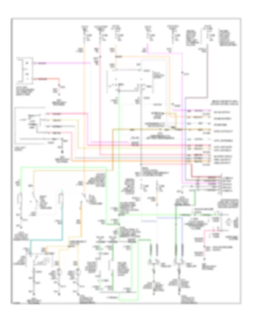
HEADLIGHTS
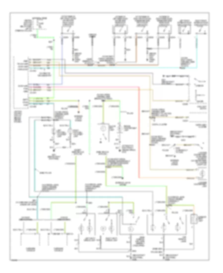
Headlamps Wiring Diagram, with DRL for Mercury Grand Marquis GS 2004
List of elements for Headlamps Wiring Diagram, with DRL for Mercury Grand Marquis GS 2004:
- (analog/marauder)
- (behind center of dash) lighting control module
- (digital)
- (in main wiring harness, in breakout to instrument cluster)
- (in right front of engine compt, behind battery) battery junction box (bjb)
- (near breakout to c1019) s149
- (near breakout to ignition switch)
- Analog/marauder
- Auto
- Auto lamp delay
- Auto lamp enable
- Auto lamp on/off
- Auto lamp/ sunload sensor (on upper left side of dash)
- Bat pwr
- Battery junction box (bjb) (in right front of engine compt, behind battery)
- C1365a
- C202c
- C205a
- C2145a
- C2145b
- C2145c
- C220b
- C220c
- C2220b
- Central junction box (cjb) (below dash, left of steering column)
- Daytime running lamps (drl) module (on front of upper radiator support)
- Digital
- Dmnd lghtng out
- Except police
- Exterior lights system
- Fog lamp relay (marauder)
- Front fog lamp cutoff relay (marauder)
- Fuse 10a
- Fuse 15a
- Fuse 20a
- Fuse 25a
- G102 (at front of right front fender apron)
- G201 (behind right kick panel)
- Ground
- Head
- Headlamp input
- Hi beam in
- Hi beam indicator
- Hot at all times
- Hot in run
- Hot in run or acc
- Hot in start or run
- Ign (run)
- Ign acc or run
- Ign start or run
- Illum
- Instrument cluster
- Left front fog lamp
- Left headlamp
- Lighting control module) s278
- Lo beam in
- Main light switch
- Main light switch (marauder)
- Multi- function switch
- Nca
- Off
- Park
- Park lamp input
- Pass
- Police
- Police, w/ wig-wag
- Police, w/o wig-wag
- Power (battery)
- Power feed
- Right front fog lamp
- Right headlamp
- S112
- S113
- S113 (except crown victoria)
- S119
- S120 (near breakout to left front brake sensor)
- S138 (in dash panel to headlamp junction harness, near breakout to horn)
- S158 (crown victoria)
- S159 (crown victoria)
- S2000 (in main wiring harness, near breakout to center of dash)
- S2009
- S204
- S207
- S210
- S242
- S262
- S269
- S276
- Wig-wag jumper 1 (on right front side of engine compt)
- Wig-wag module (on front of engine compt)
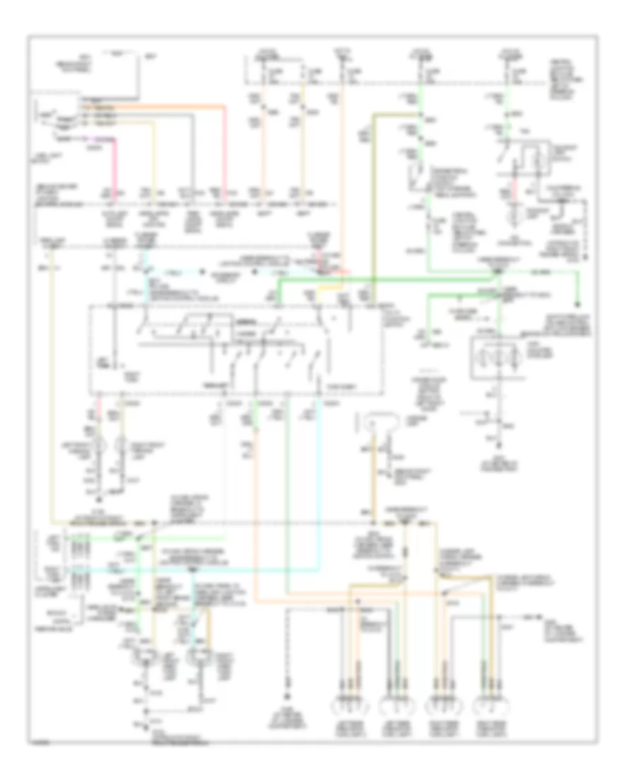
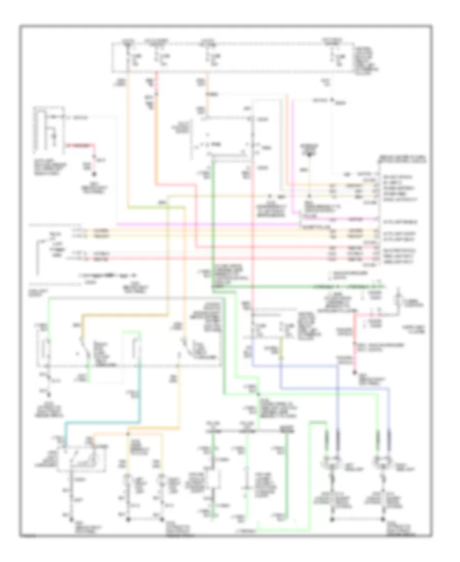
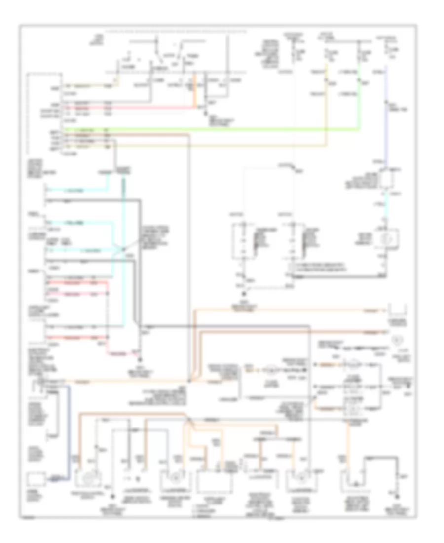
Headlamps Wiring Diagram, without DRL for Mercury Grand Marquis GS 2004
List of elements for Headlamps Wiring Diagram, without DRL for Mercury Grand Marquis GS 2004:
- (analog/marauder)
- (behind center of dash) lighting control module
- (digital)
- (in right front of engine compt, behind battery) battery junction box (bjb)
- Analog/marauder
- Auto
- Auto lamp delay
- Auto lamp enable
- Auto lamp on/off
- Auto lamp/ sunload sensor (on upper left side of dash)
- B+ (vbat 2)
- Breakout to lighting control module) s278
- C1365a
- C202c
- C205a
- C2145a
- C2145b
- C2145c
- C220b
- C220c
- C2220b
- Central junction box (cjb) (below dash, left of steering column)
- Digital
- Dmnd lghtng out
- Except police
- Exterior lights system
- Fog lamp relay (marauder)
- Front fog lamp cutoff relay (marauder)
- Fuse 10a
- Fuse 15a
- Fuse 25a
- G102 (at front of right front fender apron)
- G201 (behind right kick panel)
- Head
- Headlamp input
- Hi beam indicator
- Hot at all times
- Hot in run
- Hot in run or acc
- Hot in start or run
- Ign acc or run
- Ign start or run
- Illum
- Instrument cluster
- Left front fog lamp
- Left headlamp
- Main light switch
- Main light switch (marauder)
- Multi- function switch
- Nca
- Off
- Park
- Park lamp input
- Pass
- Police
- Police, w/ wig-wag
- Police, w/o wig-wag
- Power (battery)
- Power feed
- Right front fog lamp
- Right headlamp
- S112
- S112 (except crown victoria)
- S113
- S113 (except crown victoria)
- S120 (near breakout to left front brake sensor)
- S149 (near breakout to c1019)
- S158 (crown victoria)
- S159 (crown victoria)
- S2009
- S204
- S207
- S210
- S242 (near breakout to ignition switch)
- S262
- S269 (in main wiring harness, in breakout to instrument cluster)
- S276
- Wig-wag jumper 1 (on right front side of engine compt)
- Wig-wag module (on front of engine compt)
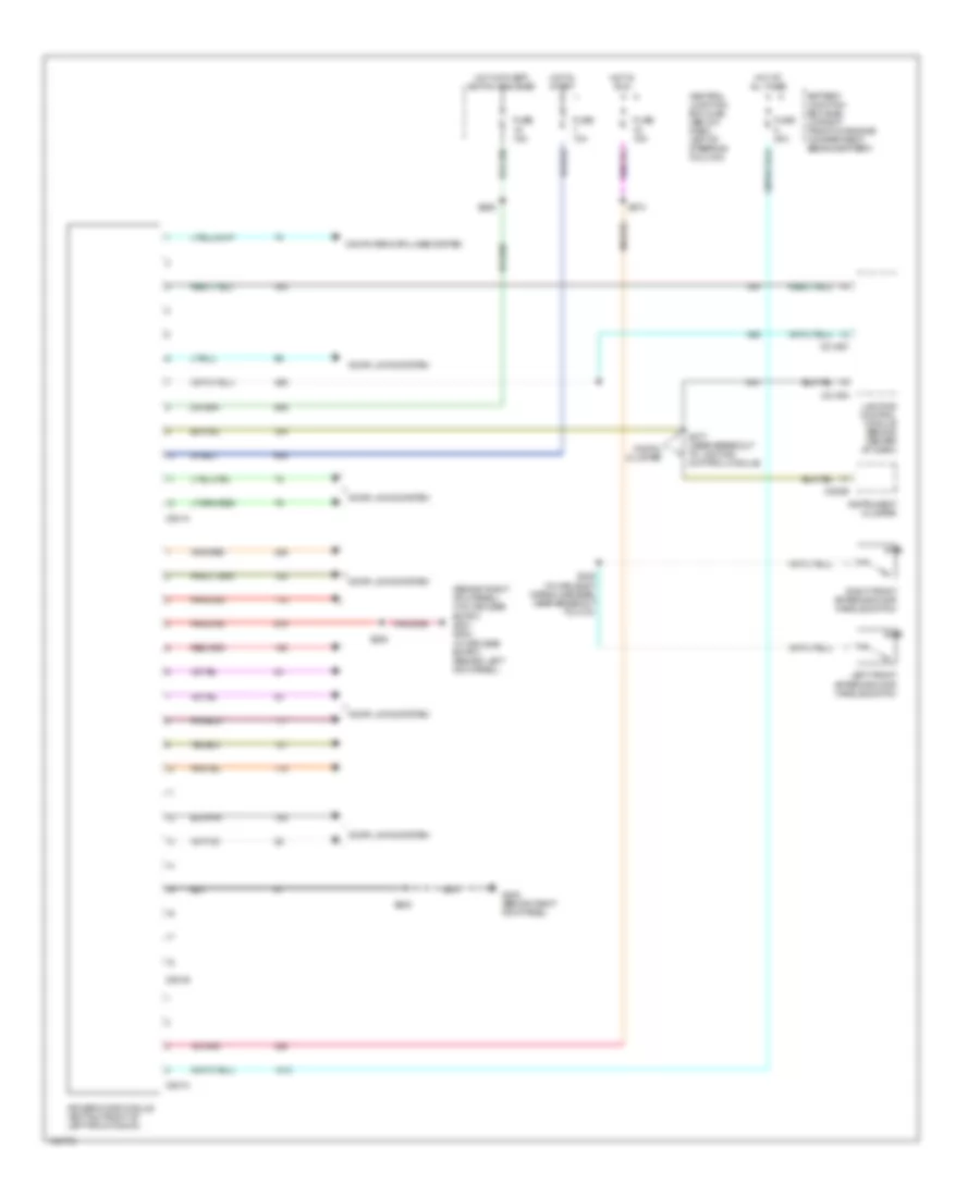
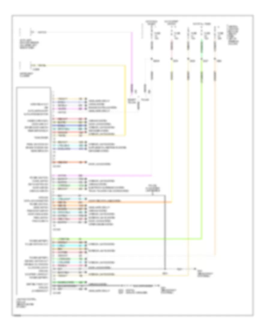
Lighting Control Module Wiring Diagram for Mercury Grand Marquis GS 2004
List of elements for Lighting Control Module Wiring Diagram for Mercury Grand Marquis GS 2004:
- (digital) (analog, marauder)
- Air bag tone drv sig
- All doors lock in
- Auto lamp/ sunload sensor (on upper left side of dash)
- Autolamps on/off
- Autolmp enab or pwr
- C2145a
- C2145b
- C2145c
- C220b
- Central junction box (cjb) (below dash, left of steering column)
- Computer data lines system
- Courtesy lamps out
- Data link connector
- Decklid ajar sw
- Defogger system
- Demand lighting out
- Dome lamp sw
- Door ajar out
- Door ajar sig
- Door handle sws
- Door locks system
- Driver door ajar sw
- Electronic suspension system
- Engine controls system
- Except police
- Exterior lights system
- Fuse 15a
- Fuse 25a
- G201 (behind right kick panel)
- Ground
- Hazard warn indic
- Headlamp sw
- Headlamps circuit
- Horn relay out
- Horns system
- Hot at all times
- Hot in run or acc
- Hot in start or run
- Instrument cluster
- Interior lights system
- Key-in-ignition sw
- Lighting control module (behind center of dash)
- Low beams out
- Panel dim down sw
- Panic alarm in
- Parklamp sw
- Pass door ajar sw
- Police
- Police, w/ courtesy lamp disable
- Power (battery)
- Power (ignition)
- Pulse width dim out
- Rear defog relay
- Rear defog sw
- S2009
- S204
- S210 s207
- S227
- S262
- S276
- S285
- Seat belt indic out
- Tone driver
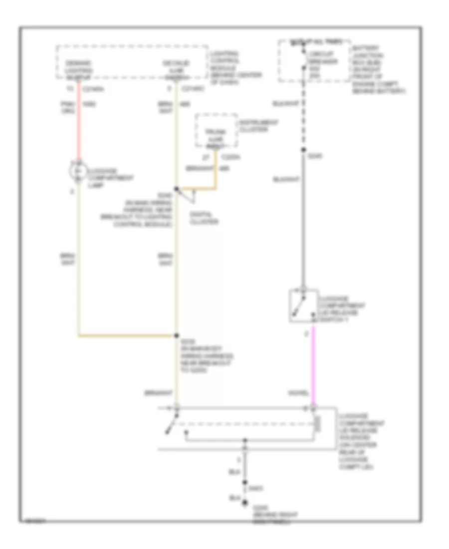
- Trunk, tailgate, fuel doors system
- Variable volt dimming
- Vss
- Warning system
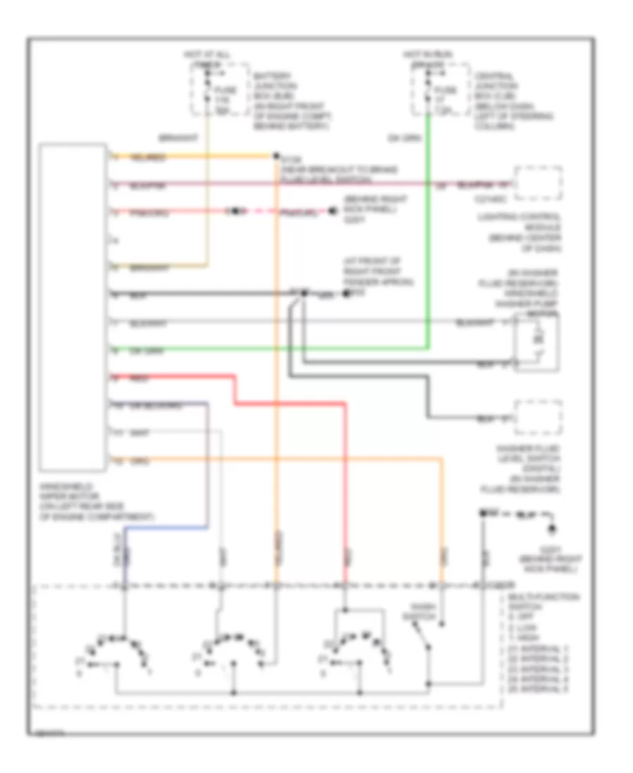
- Wiper/washer system
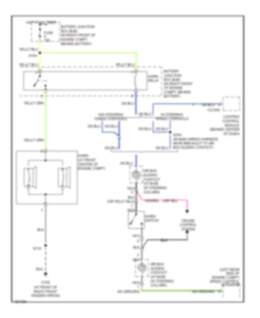
HORN
Horn Wiring Diagram for Mercury Grand Marquis GS 2004
List of elements for Horn Wiring Diagram for Mercury Grand Marquis GS 2004:
- (at front of right front fender apron)
- (left rear side of engine compt) speed control actuator
- Air bag sliding contact (at base of steering column)
- Battery junction box (bjb) (in right front of engine compt, behind battery)
- C2145a
- Cruise control system
- Fuse 15a
- G102
- Horn (at front center of engine compt)
- Horn relay
- Horn switch
- Hot at all times
- Lighting control module (behind center of dash)
- Nca
- S104
- S112
- S254 (in main wiring harness, near breakout to air bag sliding contact)
- W/ steering wheel controls
- W/o steering wheel controls
INSTRUMENT CLUSTER
Analog Cluster Wiring Diagram for Mercury Grand Marquis GS 2004
List of elements for Analog Cluster Wiring Diagram for Mercury Grand Marquis GS 2004:
- "traction control" indicator
- (6 bulbs)
- (behind right kick panel)
- (in main wiring harness, in breakout to instrument cluster) s202
- (in main wiring harness, near breakout to autolamp sensor) s209
- (in main wiring harness, near breakout to iighting control module) s247
- (not used)
- Abs
- Abs control module (at left front engine compt)
- Acc
- Air bag indicator
- Air suspension module (behind right side of dash, above glove box)
- Airbag indicator
- Anti-slosh module
- Battery junction box (bjb) (in right front of engine compt, behind battery)
- Brake fluid level switch (on brake fluid reservoir)
- Brake ind ctrl
- C2131a
- C2145b
- C2220a
- C2220b
- C310b
- Central junction box (cjb) (below dash, left of steering column)
- Charge indicator
- Check fuel cap indicator
- Check gauge ind
- Check suspension indicator
- Ect sensor in
- Engine coolant temperature (ect) sensor (on top right front of engine, near fuel injector 1)
- Engine coolant temperature gauge
- Exterior lights system
- Fail-safe cooling
- Fuel gauge
- Fuel level in
- Fuel tank unit (at top of fuel tank)
- Fuse 10a
- Fuse 15a
- Fuse 30a
- G101 (at rear of left front fender apron)
- G102 (at front of right front fender apron)
- G200 (behind right kick panel)
- G201
- G201 (behind right kick panel)
- Gnd
- Headlights system
- Hi beam indicator
- Hot at all times
- Hot in run
- Hot in start or run
- Ignition switch
- Illumination lamps
- Ind ctrl
- Indicator
- Indicator control
- Indicator out
- Indicator output
- Instrument cluster
- Interior lights system
- Left turn indicator
- Lighting control module (behind center of dash)
- Lock
- Low
- Low brake fluid level/ park brake ind
- Low fuel indicator
- Low oil pressure gauge
- Malfunction indicator lamp (mil)
- Microprocessor
- Mil output
- Nca
- Normal
- Off
- Oil pressure switch (on lower left side of engine, above oil filter)
- Overdrive cancel
- Parking brake switch (behind left side of dash, on top of parking brake assembly)
- Powertrain control module (pcm) (in engine compt, on left side of firewall)
- Restraints control module (in left front footwell)
- Right turn indicator
- Run
- S100
- S112
- S124 (left rear of engine compt)
- S128
- S141 (near breakout to c1026)
- S204
- S207
- S210
- S231
- S276
- S500
- Safety belt indicator
- Speedometer
- Start
- Tcil
- Traction ind out
- Voltmeter
- Vss(+)
Electronic Cluster Wiring Diagram (1 of 2) for Mercury Grand Marquis GS 2004
List of elements for Electronic Cluster Wiring Diagram (1 of 2) for Mercury Grand Marquis GS 2004:
- (in dash panel to headlamp junction harness, near breakout to c1026) s141
- (in main wiring harness, in breakout to instrument cluster) s202
- (in main wiring harness, on left rear side of engine compartment)
- (left rear of engine compartment)
- (on top right front of engine, near fuel injector 1) engine coolant temperature (ect) sensor
- 10a
- 15a
- Abs control module (at left front of engine compt)
- Air susp ind
- Air suspension module (behind right side of dash, above glove box)
- C2131a
- C220a
- C220b
- C220c
- C228b
- Central junction box (cjb) (below dash, left of steering column)
- Charge ind
- Door ajar ind
- E/m
- Ect ind
- Electronic automatic temperature control (eatc) module (behind center of dash)
- Eng/met
- Exterior lights system
- Fail-safe cooling ind
- Fuel cap ind
- Fuel level data
- Fuel level ind
- Fuel tank unit (at top of fuel tank)
- Fuse
- G102 (at front of right front fender apron)
- G201 (behind right kick panel)
- Gnd
- Headlights system
- Hi beam ind
- Hot at all times
- Hot in run
- Illum
- Illumination
- Ind
- Instrument cluster
- Interior lights system
- Left turn ind
- Low washer fluid ind
- Message center switch
- Microprocessor
- Mil ind
- Nca
- Oil pres ind ind
- Oil pressure switch (on lower left side of engine, above oil filter)
- Out
- Output
- Powertrain control module (pcm) (in engine compt, on left side of firewall)
- Red
- Reset
- Right turn ind
- S112
- S121
- S128
- S210
- S227
- S231
- S247 (near breakout to lighting control module)
- Safety belt indicator
- Select
- Speed control actuator (left rear side of engine compartment)
- Speed control ind
- Speedometer
- Starting/charging system
- Tcil ind
- Tone driver
- Traction assist ind
- Trunk ajar ind
- Vbatt
- Vpwr
- Vref
- Washer fluid level switch (in washer fluid reservoir)
Electronic Cluster Wiring Diagram (2 of 2) for Mercury Grand Marquis GS 2004
List of elements for Electronic Cluster Wiring Diagram (2 of 2) for Mercury Grand Marquis GS 2004:
- (left side of dash) (taxi) s282
- (taxi)
- Ajar lamp output
- C2145a
- C2145b
- C2145c
- C2212a
- C2212b
- C501a
- C526a
- C602a
- C602b
- C715a
- C715b
- C820b
- Decklid jar
- Door ajar
- Door ajar indicator (taxi)
- Driver door module (bottom front of left front door)
- Driver side front door ajar switch (at top rear of left front door) c526b
- Driver side rear door ajar switch (at rear of left rear door)
- Driver's ajar switch
- G200 (behind right kick panel)
- Input
- Lighting control module (behind center of dash)
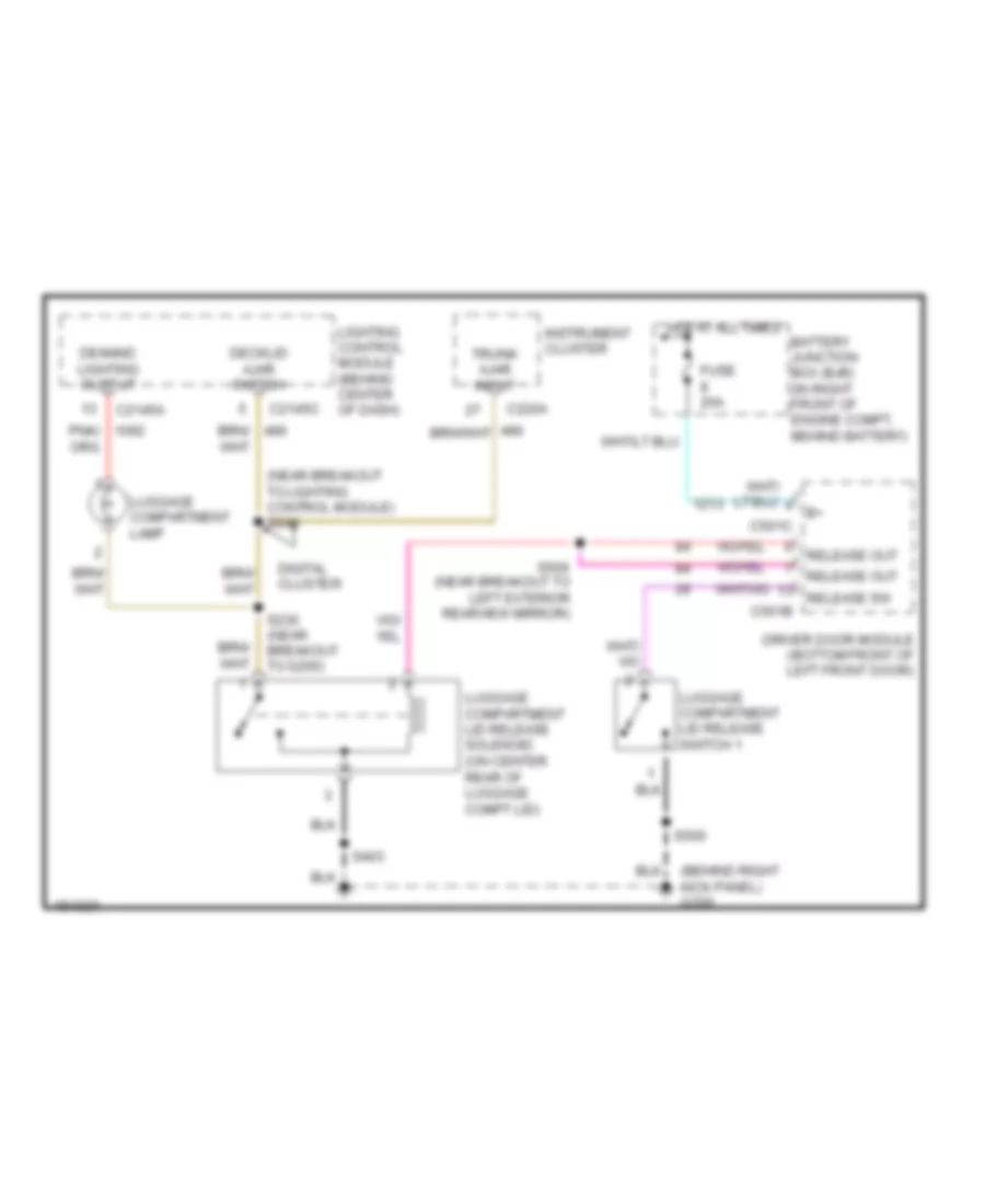
- Luggage compartment lid release solenoid (on center rear of luggage compartment lid)
- Pass ajar switch
- Passenger side front door ajar switch (at top rear of right front door)
- Passenger side rear door ajar switch (at rear of right rear door) c820a
- S230 (in main body wiring harness, near breakout to g200)
- S240 (in main wiring harness, near breakout to lighting control module)
- S259 (in main body wiring harness, near breakout to g200)
- S277 (in main wiring harness, near breakout to lighting control module)
- S280 (in main wiring harness, near breakout to c213)
- S403
- S500
- S600
- Seatbelt ind out
- Seatbelt switch
- Tone request
- Trunk, tail, fuel doors system
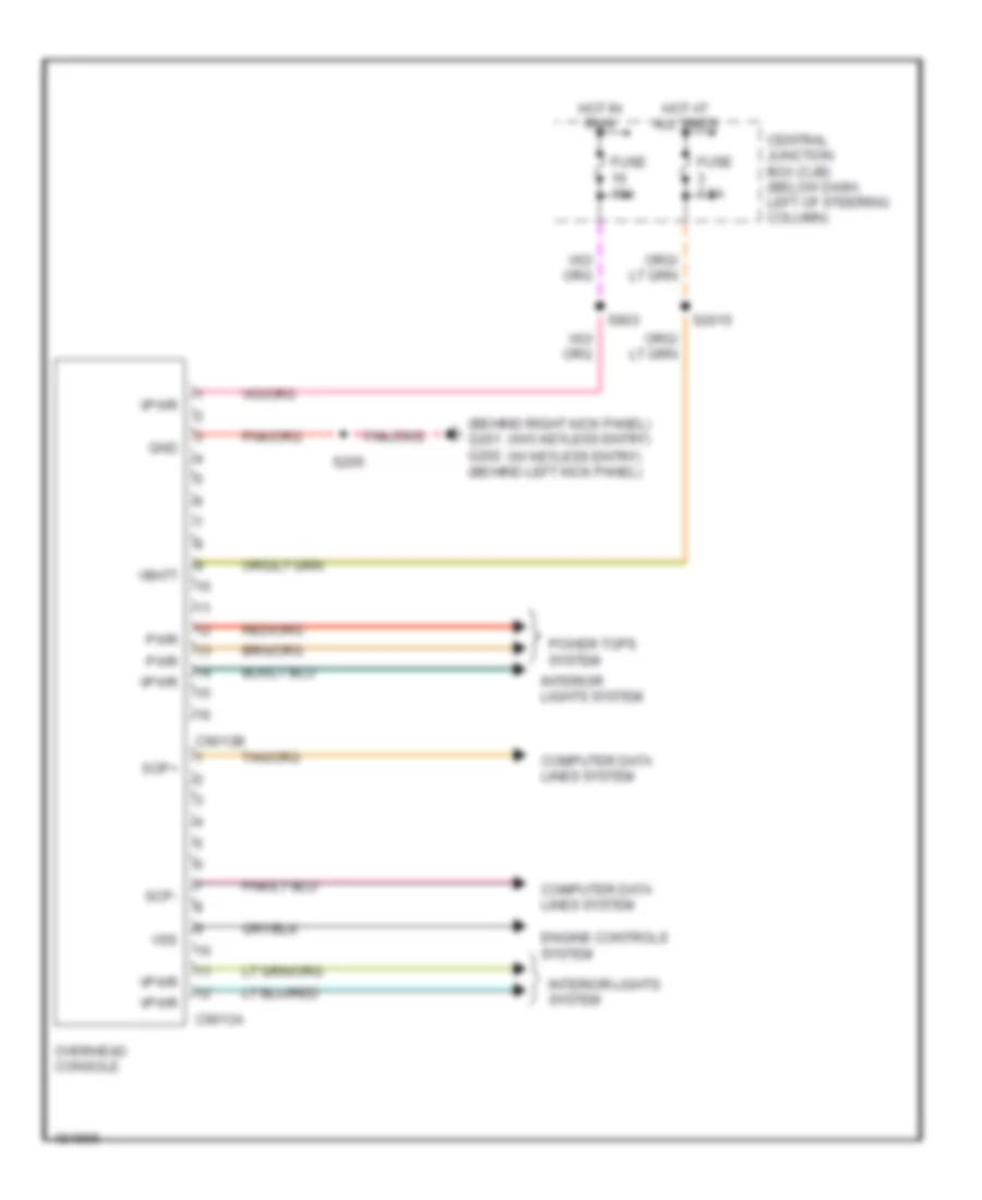
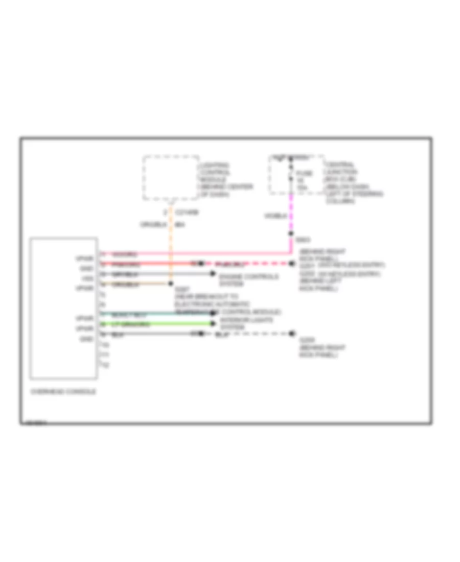
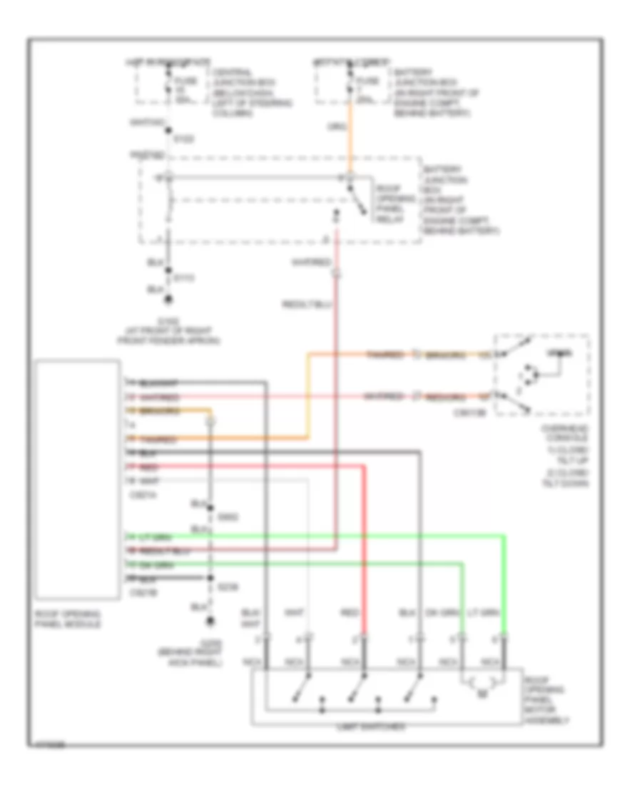
Overhead Console Wiring Diagram, with Roof Opening Panel for Mercury Grand Marquis GS 2004
List of elements for Overhead Console Wiring Diagram, with Roof Opening Panel for Mercury Grand Marquis GS 2004:
- (behind right kick panel) g201 g202 (behind left kick panel)
- (w/ keyless entry)
- (w/o keyless entry)
- C9013a
- C9013b
- Central junction box (cjb) (below dash, left of steering column)
- Computer data lines system
- Engine controls system
- Fuse 15a
- Fuse 7.5a
- Gnd
- Hot at all times
- Hot in run
- Interior lights system
- Overhead console
- Power tops system
- Pwr
- S2015
- S205
- S903
- Scp+
- Scp-
- Vbatt
- Vpwr
- Vss
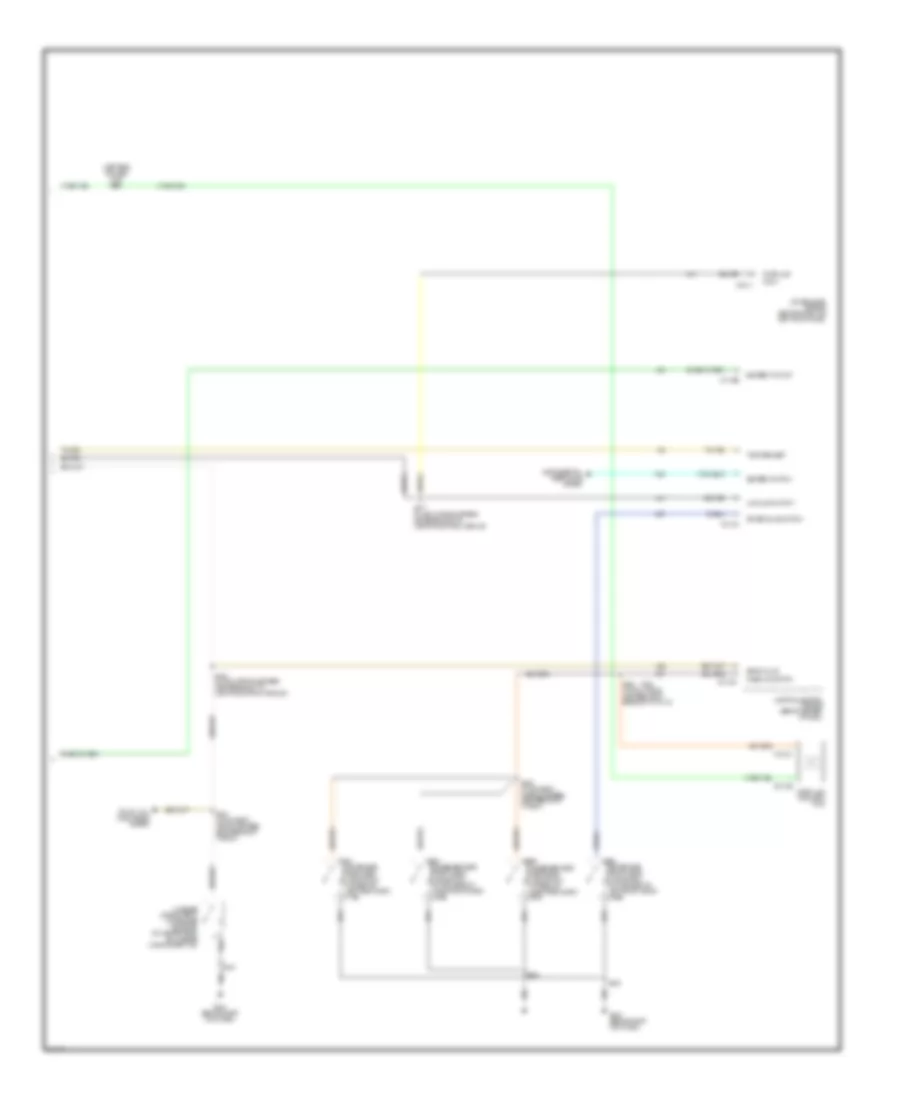
Overhead Console Wiring Diagram, without Roof Opening Panel for Mercury Grand Marquis GS 2004
List of elements for Overhead Console Wiring Diagram, without Roof Opening Panel for Mercury Grand Marquis GS 2004:
- (behind right kick panel) g201 g202 (behind left kick panel)
- (w/ keyless entry)
- (w/o keyless entry)
- C2145b
- Central junction box (cjb) (below dash, left of steering column)
- Engine controls system
- Fuse 15a
- G200 (behind right kick panel)
- Gnd
- Hot in run
- Interior lights system
- Lighting control module (behind center of dash)
- Overhead console
- S205
- S287 (near breakout to electronic automatic temperature control module)
- S902
- S903
- Vpwr
- Vss
INTERIOR LIGHTS
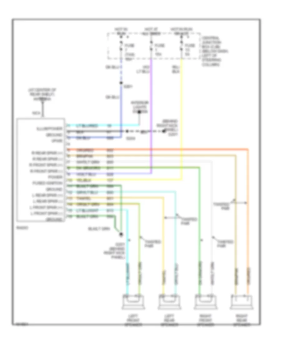
Courtesy Lamps Wiring Diagram for Mercury Grand Marquis GS 2004
List of elements for Courtesy Lamps Wiring Diagram for Mercury Grand Marquis GS 2004:
- (at front of right front fender apron) g102
- (at rear of left rear door) driver side rear door ajar switch
- (at rear of right rear door) passenger side rear door ajar switch
- (at top rear of left front door) driver side front door ajar switch
- (at top rear of right front door) passenger side front door ajar switch
- (base) s208
- (behind right kick panel) g200
- (in interior lamps wiring harness, in breakout to c327)
- (in interior lamps wiring harness, in breakout to c327) s900
- (in interior lamps wiring harness, near breakout to c327)
- (in main body wiring harness, near breakout to c214) s238
- (in main body wiring harness, near breakout to g200) s230
- (in main body wiring harness, near breakout to g200) s259
- (in main wiring harness, near breakout to lighting control module) s240
- (in main wiring harness, near breakout to radio) s236
- (in main wiring harness, near breakout to radio) s290
- (near breakout to c213) s280
- (police) s902
- Base vehicle & police
- Base, police
- C205b
- C2145a
- C2145b
- C2145c
- C220a
- C9013a
- C9013b
- Central junction box (cjb) (below dash, left of steering column)
- Digital cluster
- Dimmer
- Door actuator) s302
- Door ajar
- Engine compartment lamp
- Except base vehicle & police
- Exterior lights system
- Fuse 15a
- G201 (behind right kick panel)
- Glove box lamp
- Handle sw
- Hot at all times
- Instrument cluster
- Interior
- Interior spot lamp
- Left footwell courtesy lamp
- Left front exterior door handle switch
- Left vanity mirror lamp
- Lighting control module (behind center of dash)
- Luggage compartment lamp
- Luggage compartment lid release solenoid (on center rear of luggage compt lid)
- Main light switch
- Map reading lamps
- Nca
- Overhead console
- Police
- Pwr
- Rear interior/ map lamps assembly (if equipped)
- Right footwell courtesy lamp
- Right front exterior door handle switch
- Right vanity mirror lamp
- S112
- S204
- S207
- S227
- S403
- S450 (in breakout to c408)
- S500
- S600
- S900
- S901 (w/ overhead console & rear map lamps)
- S902
- Taxi
- Trunk ajar
- Vbatt
- Vpwr
- Vref
- W/ roof opening panel
- W/o remote keyless entry
- W/o roof opening panel
- Warning system
Instrument Illumination Wiring Diagram for Mercury Grand Marquis GS 2004
List of elements for Instrument Illumination Wiring Diagram for Mercury Grand Marquis GS 2004:
- (behind right kick panel)
- (in console panel wiring harness, near breakout to c219)
- (in main wiring harness, near breakout to in-vehicle temperature sensor)
- (w/ remote keyless entry)
- (w/o remote keyless entry)
- Adjustable pedal switch (behind left side of dash)
- Air bag sliding contact (at base of steering column)
- Alpine radio
- Analog
- Audio/ climate control switch
- Auto
- C205a
- C205b
- C2145a
- C2145b
- C2145c
- C220b
- C220c
- C220c c2220b c2220b
- C228a
- C228b
- C290c
- C294d
- C501a
- C9013a
- Central junction box (cjb) (below dash, left of steering column)
- Crown victoria/ grand marquis w/ center console
- Digital
- Dimmer
- Driver door module (bottom front of left front door)
- Driver side door lock switch
- Electronic automatic temperature control (eatc) module (behind center
- Electronic automatic temperature control (eatc) module (behind center of dash)
- Except police
- Floor shifter
- Function selector switch assembly
- Fuse 10a
- Fuse 15a
- G200 (behind right kick panel)
- G201
- G201 (behind right kick panel)
- Head
- Hot at all times
- Hot in run
- Hot in run or acc
- Illum
- Illumination
- Instrument cluster
- Instrument cluster (digital cluster)
- Interior
- Key pad switch assembly
- Lighting control module (behind center of dash)
- M100 radio
- Main light switch
- Marauder
- Message center switch (digital)
- Nca
- Of dash)
- Off
- Oil pressure gauge
- On/off sig
- Overhead console
- Park
- Passenger side door lock switch
- Police
- Pwr
- Radio
- Rear window defrost switch
- S2008
- S201 (base, taxi)
- S204
- S207
- S210
- S224
- S227
- S233
- S248
- S285
- S287 (in main wiring harness, near breakout to electronic automatic temperature control module)
- S288
- S600
- Speed control switch
- Traction control switch
- Vbatt
- Voltmeter
- Vref
- W/ eatc
- W/o eatc
POWER DISTRIBUTION
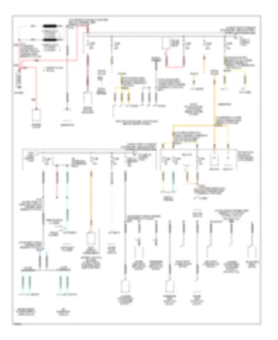
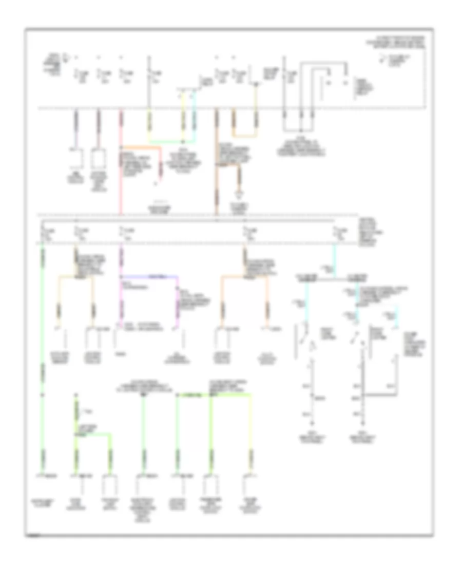
Power Distribution Wiring Diagram (1 of 5) for Mercury Grand Marquis GS 2004
List of elements for Power Distribution Wiring Diagram (1 of 5) for Mercury Grand Marquis GS 2004:
- (in emergency jumper wiring harness, near breakout for c298) s2022
- (in main body wiring harness, near breakout to c214) s206
- (in main body wiring harness, near breakout to g204) s245
- (in main wiring harness, near breakout to lighting control module)
- (in police auxiliary junction box front jumper wiring harness, at breakout for c275) s2011
- (in power distribution wiring harness, at breakout for police glove box relay/fuse center) s2036
- (in right front of engine compartment, behind battery) battery junction box (bjb)
- (in starter motor relay & battery ground harness, near breakout to c146) s152
- (not used)
- (police w/ 4.6l) s250
- Adjustable pedal switch
- Air suspension compressor relay
- Air suspension module
- Analog cluster
- Battery
- Battery junction box (bjb) (in right front of engine compt, behind battery)
- C1365b
- C2131b
- C2220a
- C2231b
- C2232a
- C2232b
- C2232d
- C501c
- Circuit breaker 20a
- Crown police
- Driver door module
- Driver side door lock switch
- Driver side front seat adjust switch
- Ends in harness
- Engine cooling fan motor
- Except police
- From a fuse 6 (diagram 1 of 5)
- Front police auxiliary junction box (behind center of dash)
- Fuse 15a
- Fuse 20a
- Fuse 25a
- Fuse 30a
- Fuse 50a
- Fuse a1 10a
- Fuse a2 5a
- Fuse a3 5a
- Generator
- Instrument cluster
- Left front lumbar adjust switch
- Luggage compartment lid release switch 1
- Luggage compartment lid release switch 2 (police w/ 4.6l)
- Nca
- Passenger side door lock switch
- Passenger side front seat adjust switch
- Performance cluster
- Police
- Police glove box relay/ fuse center (in glove box)
- Police power relay
- Red
- Relay a1
- Relay a2
- Relay a4
- Right front lumbar adjust switch
- Roof opening panel relay
- S100 (in dash panel to headlamp junction harness, near breakout to g102)
- S114 (in starter motor relay & battery ground harness, near breakout to c146)
- S289
- Starter motor
- Tan
- To fuse 106 (diagram 2 of 5)
- To fuse 114 (diagram 1 of 5)
- Trunk ends in harness
- Variable assist power steering (vaps) module
- W/ air suspension
- W/o air suspension
- Wig-wag module
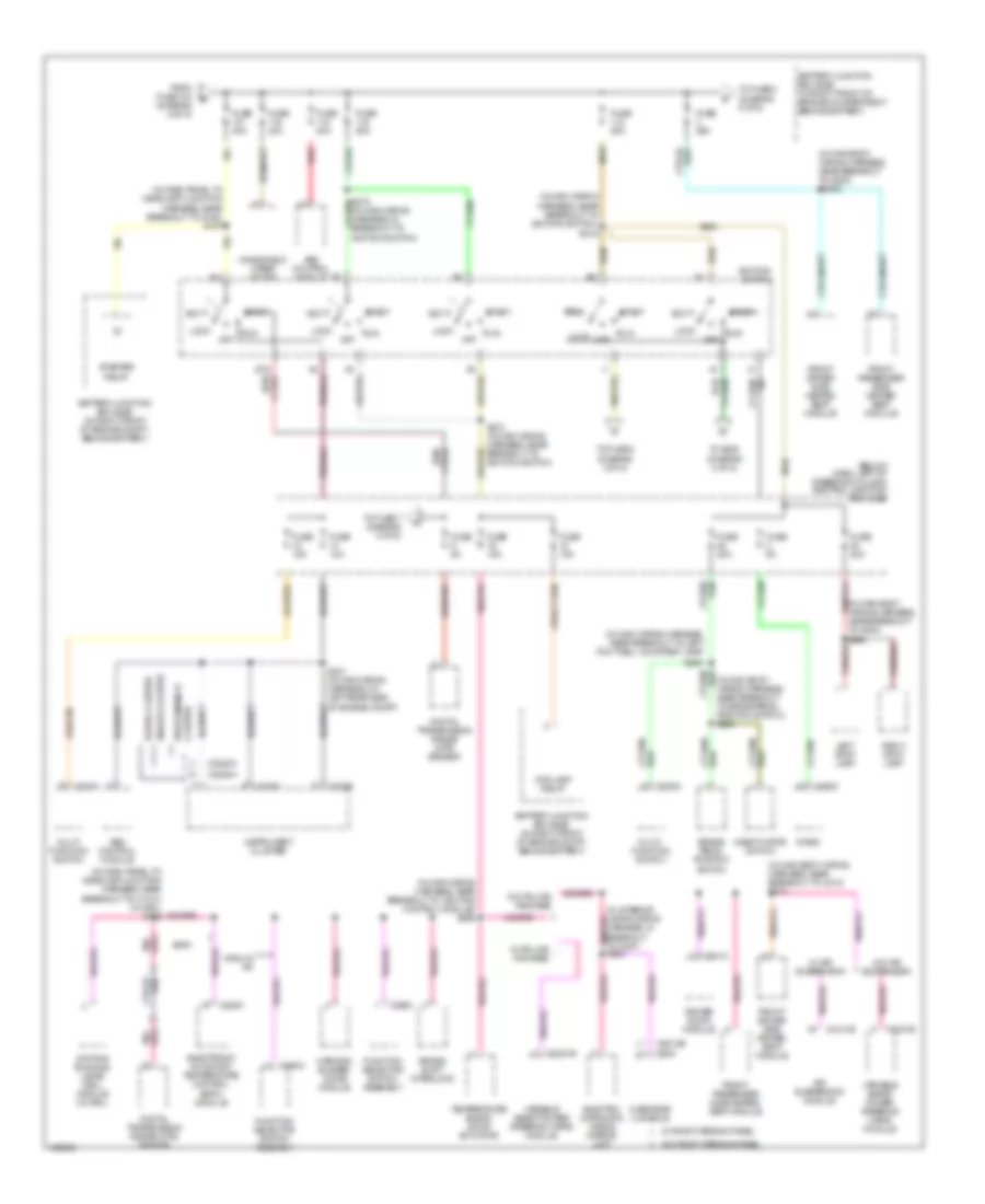
Power Distribution Wiring Diagram (2 of 5) for Mercury Grand Marquis GS 2004
List of elements for Power Distribution Wiring Diagram (2 of 5) for Mercury Grand Marquis GS 2004:
- (at rear of center console)
- (behind right kick panel)
- (in console panel wiring harness, in breakout to power point) (marauder) s249
- (in main body wiring harness, near breakout to g204) s228
- (in main wiring harness, near breakout to adjustable pedal switch) s285
- (in main wiring harness, near breakout to ignition switch) s262
- (in main wiring harness, near breakout to left footwell courtesy lamp) s239
- (in main wiring harness, near breakout to lighting control module) s227
- (in right front of engine compartment, behind battery) battery junction box (bjb)
- (left side of dash) s282
- (m100 radio) (apline radio)
- Abs control module
- Autolamp/ sunload sensor
- Blower motor relay
- C202c
- C2145b
- C220b
- C2212b
- C228a
- C240 c290c
- Cd changer (alpine radio)
- Central junction box (cjb) (below dash, left of steering column)
- Daytime running lamps (drl) module
- Door ajar indicator
- Driver side door lock switch
- Electronic automatic temperature control (eatc) module
- From circuit breaker (diagram 1 of 5)
- Front cigar lighter
- Fuse 15a
- Fuse 20a
- Fuse 25a
- Fuse 40a
- Fuse 50a
- G201
- Horn relay
- Instrument cluster
- Lighting control module
- Multi- function switch
- Passenger side door lock switch
- Power point (marauder)
- Radio
- Rear window defrost relay
- S104 (in dash panel to headlamp junction harness, near breakout to g102)
- S153 (in dash panel to headlamp junction harness, near breakout to battery junction box)
- S2002 (in main wiring harness, on left rear side of engine compt)
- S2006
- S213 (alpine radio)
- S248
- S410 (in taillamps wiring harness, near breakout to c410)
- Subwoofer amplifier
- Taxi
- Taxi roof lamp switch
- To fuse 101 (diagram 3 of 5)
- To fuse 3 (diagram 5 of 5)
- W/ center console
- W/o center console
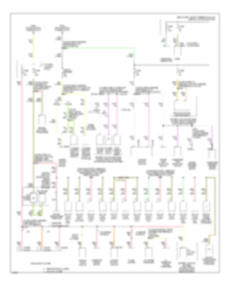
Power Distribution Wiring Diagram (3 of 5) for Mercury Grand Marquis GS 2004
List of elements for Power Distribution Wiring Diagram (3 of 5) for Mercury Grand Marquis GS 2004:
- (below dash, left of steering column) central junction box (cjb)
- (in dash panel to headlamp junction harness, near breakout to g102) s127
- (in main body wiring harness, near breakout to brake pedal position switch) s265
- (in main body wiring harness, near breakout to c214) s274
- (in main body wiring harness, near breakout to g200) s2003
- (in main body wiring harness, near breakout to g204) s268
- (in main wiring harness, near breakout to ignition switch) s219
- (in main wiring harness, near breakout to left footwell courtesy lamp)
- (in main wiring harness, near breakout to lighting control module) s266
- Abs control module
- Acc
- Air suspension module
- Analog cluster
- Battery junction box (bjb) (in right front of engine compartment, behind battery)
- Battery junction box (bjb) (in right front of engine compt, behind battery)
- Brake pedal position switch
- Brake shift interlock
- C202a
- C2131b
- C220b
- C220c
- C2220a
- C2231b
- C228a
- C290c
- C294c
- C501c
- C9013b
- C930
- Daytime running lamps (drl) module (w/ drl)
- Deactivator switch
- Digital cluster
- Digital transmission range (dtr) sensor
- Driver door module
- Eatc
- Electro- chromatic inside mirror unit
- Electronic automatic temperature control (eatc) module
- Fog lamp relay
- From fuse 104 (diagram 2 of 5)
- Front driver side heated seat module
- Front passenger side heated seat module
- Function selector switch assembly
- Fuse 10a
- Fuse 15a
- Fuse 20a
- Fuse 25a
- Fuse 30a
- Fuse 50a
- Fuse 5a
- Ignition switch
- Instrument cluster
- Left stop lamp
- Lock
- Manual a/c
- Multi- function switch
- Off
- Overhead console
- Performance cluster
- Radio
- Red
- Right stop lamp
- Run
- S231 (in main wiring harness, on left rear side of engine compt)
- S263
- S270 (in main wiring harness, near breakout to ignition switch)
- Start
- Starter relay
- Temperature blend door actuator
- To fuse 5 (diagram 5 of 5)
- To fuse 7 (diagram 5 of 5)
- To fuse 8 (diagram 4 of 5)
- To s225 (diagram 4 of 5)
- Variable assist power steering (vaps) module
- W/ air suspension
- W/ police package
- W/ roof opening panel
- W/o air suspension
- W/o police package
- W/o roof opening panel
- Warning buzzer/ chime module
- Windshield wiper motor
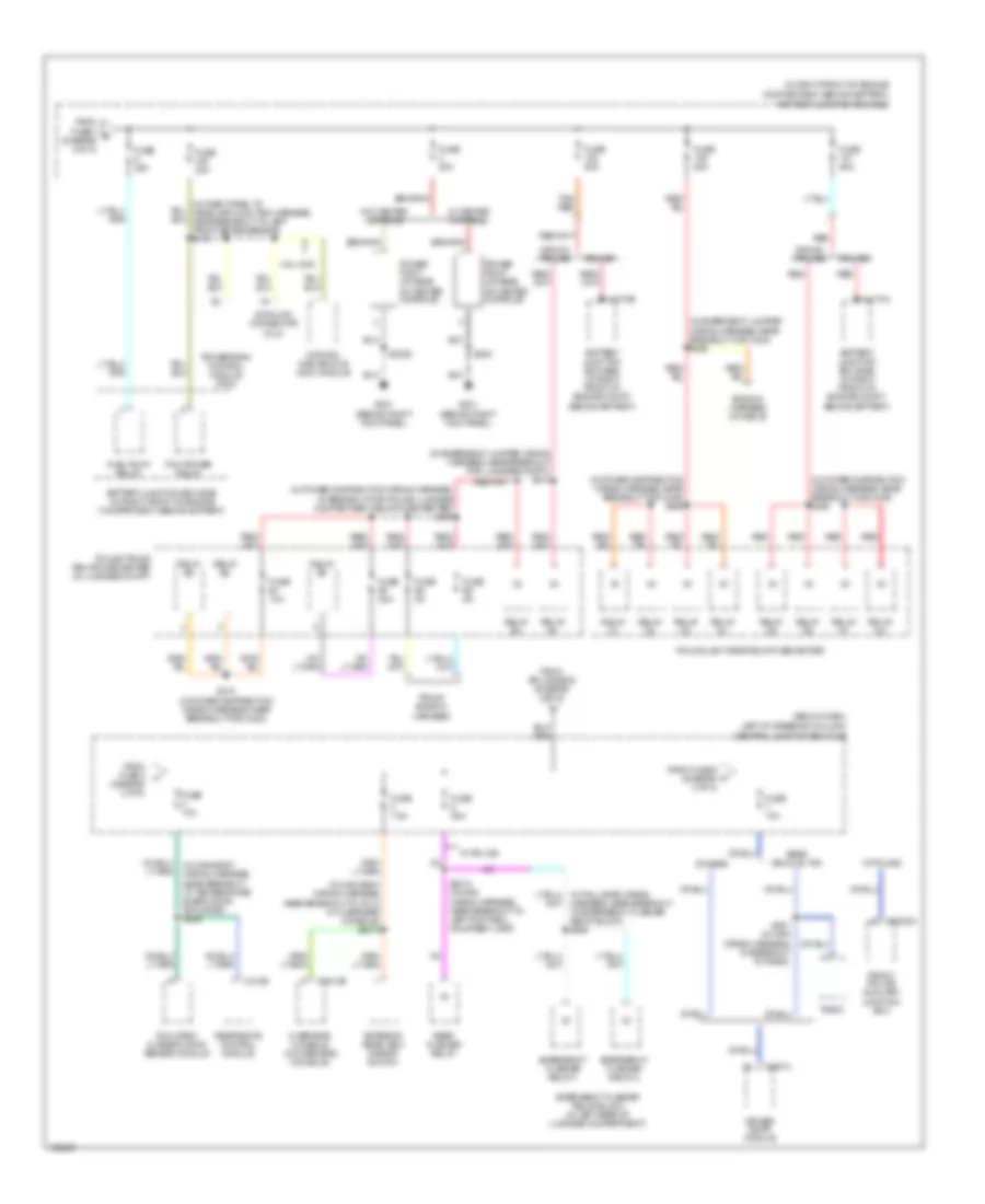
Power Distribution Wiring Diagram (4 of 5) for Mercury Grand Marquis GS 2004
List of elements for Power Distribution Wiring Diagram (4 of 5) for Mercury Grand Marquis GS 2004:
- (below dash, left of steering column) central junction box (cjb)
- (in console panel wiring harness, near breakout to c219) (marauder) s2007
- (in dash panel to headlamp junction harness, near breakout to c1010) s117
- (in engine control sensor & fuel charge wiring harness, near breakout to c1033) s151
- (in engine control sensor & fuel charge wiring harness, near breakout for left rear of engine) s103
- (in main body wiring harness, near breakout to g204) s218
- (in main wiring harness, near breakout to adjustable pedal switch) s2009
- (in main wiring harness, near breakout to autolamp sensor) s276
- (in main wiring harness, near breakout to function selector switch assembly) (w/ police) s211
- (in main wiring harness, near breakout to ignition switch) s225
- (in right front of engine compt, behind battery) battery junction box (bjb)
- (m100 radio) (alpine radio)
- 4.6l
- 4.6l w/ digital cluster
- A/c clutch relay
- Analog cluster
- Battery junction box (bjb) (in right front of engine compartment, behind battery)
- Battery junction box (bjb) (in right front of engine compt, behind battery)
- Blower motor relay
- C2145a
- C2145c
- C2220a
- C2220b
- C240 c290c
- C504b
- Circuit breaker 20a
- Coil on plug (cop) 1
- Coil on plug (cop) 2
- Coil on plug (cop) 3 (4.6l cng)
- Coil on plug (cop) 3 (4.6l)
- Coil on plug (cop) 4 (4.6l cng)
- Coil on plug (cop) 4 (4.6l)
- Coil on plug (cop) 5 (4.6l cng)
- Coil on plug (cop) 5 (4.6l)
- Coil on plug (cop) 6 (4.6l cng)
- Coil on plug (cop) 6 (4.6l)
- Coil on plug (cop) 7
- Coil on plug (cop) 8
- Driver side door lock switch
- Driver side seat heater switch
- Except marauder
- Floor shifter
- From ignition switch (diagram 3 of 5)
- Fuse 15a
- Fuse 25a
- Fuse 5a
- Fuse 7.5a
- Headlamp junction harness, near breakout to g102) s154
- Ignition trans- former capacitor 1 (marauder)
- Ignition transformer capacitor
- Ignition transformer capacitor 2 (marauder)
- Instrument cluster
- Lighting control module
- Luggage compart- ment lid release switch 1
- Luggage compart- ment lid release switch 3 (w/ police)
- Marauder
- Master window adjust switch
- Nca
- Oil pressure gauge (marauder)
- Overdrive cancel switch
- Passenger side door lock switch
- Passenger side seat heater switch
- Passive anti-theft transceiver
- Pcm power diode
- Pcm power relay
- Performance cluster
- Police power relay
- Radio
- Red/ (in main wiring harness, on left rear side of engine compt) s223
- Roof opening panel relay
- Speed control actuator
- To fuse 4 (diagram 5 of 5)
- Traction control indicator relay
- Voltmeter (marauder)
- W/ center console
- W/ eatc
- W/ police
- W/o center console
- W/o police
- Warning lamps module
- Windshield wiper motor
Power Distribution Wiring Diagram (5 of 5) for Mercury Grand Marquis GS 2004
List of elements for Power Distribution Wiring Diagram (5 of 5) for Mercury Grand Marquis GS 2004:
- (behind right kick panel)
- (below dash,
- (in dash panel to headlamp junction harness, near breakout to left front brake sensor) s115
- (in emergency jumper wiring harness, near breakout for c300) s350
- (in emergency jumper wiring harness, near breakout for luggage compt) s470
- (in main body wiring harness, near breakout to c213) (w/ overhead console) s2015
- (in main body wiring harness, near breakout to temperature blend door actuator) s229
- (in power distribution wiring harness, at breakout for police luggage compartment relay/fuse center) s478
- (in power distribution wiring harness, near breakout for c406) s462
- (in power distribution wiring harness, near breakout for c406) s466
- (in right front of engine
- 4.6l cng
- Base vehicle, taxi
- Battery junction box (bjb) (in right front of engine compartment, behind battery)
- Battery junction box (bjb) (in right front of engine compt, behind battery)
- C2232a
- C310b
- C4170a
- C4170b
- C501a
- C9013b
- Compartment, behind battery) battery junction box (bjb)
- Crown police
- Data link connector (dlc)
- Driver door module
- Emergency flasher relay 1
- Emergency flasher relay 2
- Emergency flasher relay block (in left rear of luggage compartment)
- Ends in harness console
- Exterior rear view mirror switch
- From fuse 3 s (diagram 3 of 5)
- From fuse 8 (diagram 4 of 5)
- From fuse 9 (diagram 3 of 5)
- From splice s239 (diagram 2 of 5)
- Front police auxiliary junction box
- Fuel pump relay
- Fuse 10a
- Fuse 20a
- Fuse 25a
- Fuse 30a
- Fuse 50a
- Fuse 7.5a
- Fuse b1 10a
- Fuse b2 5a
- Fuse b3 5a
- Fuse b7 20a
- G201
- Left of steering column) central junction box (cjb)
- Natural gas vehicle (ngv) module
- Occupant classification sensor module
- Others
- Overhead console (w/ overhead console)
- Pcm power relay
- Police
- Police light bar relay/fuse center
- Police trunk relay/fuse center (in luggage compt)
- Power point (at rear of center console)
- Powertrain control module (pcm)
- Radio
- Rear flasher relay
- Red
- Relay b1
- Relay b2
- Relay b3
- Relay b4
- Relay b5
- Relay c1
- Relay c2
- Relay c3
- Relay c4
- Relay c5
- Relay c6
- Relay c7
- Relay c8
- Restraints control module
- S2006
- S201 (in main wiring harness, in breakout to radio)
- S2012 (in main wiring harness, near breakout to left footwell courtesy lamp)
- S248
- S474 (in power distribution wiring harness, near breakout for c422)
- Tan/ red
- Trunk ends in harness
- W/ center console
- W/ police
- W/o center console
POWER DOOR LOCKS
Power Door Locks Wiring Diagram, with Keyless Entry for Mercury Grand Marquis GS 2004
List of elements for Power Door Locks Wiring Diagram, with Keyless Entry for Mercury Grand Marquis GS 2004:
- (near breakout to c214)
- (near breakout to fuel door release switch)
- (near breakout to left exterior rearview mirror) s506
- (near breakout to lighting control module)
- 1/2
- 3/4
- 5/6
- 7/8
- 9/0
- Battery junction box (bjb) (in right front of engine compt, behind battery)
- C2145a
- C2145b
- C220b
- C501a
- C501b
- C501c
- Central junction box (cjb) (below dash, left of steering column)
- Digital
- Door ajar
- Door ajar ind
- Door lock
- Driver door module (bottom front of left front door)
- Driver side door lock switch
- Fuse 10a
- Fuse 15a
- Fuse 20a
- G200 (behind right kick panel)
- Hndl sw sig rtn c2145c
- Hot at all times
- Hot in run or acc
- Hot in start
- Illum
- Illumination
- Instrument cluster
- Key pad illum
- Key pad sw a
- Key pad sw b
- Key pad sw c
- Key pad switch assembly
- Left front door lock actuator (at bottom rear of left front door)
- Left front exterior door handle switch
- Left rear door lock actuator (at rear of left rear door)
- Lighting control module (behind center of dash)
- Lock
- Luggage compartment lid release solenoid (on center rear of luggage compt lid)
- Luggage compt lid release switch 1
- Nca
- Passenger side door lock actuator (at bottom rear of right front door)
- Passenger side door lock switch
- Pwr
- Right front exterior door handle switch
- Right rear door lock actuator (at rear of right rear door)
- S201 (base, taxi)
- S228
- S235 (near breakout to g204)
- S238
- S260 (near breakout to g204)
- S261 (near breakout to g200)
- S277
- S288
- S403
- S500
- S501
- S510 (near breakout to exterior rearview mirror switch)
- S600
- Sig rtn
- Trunk lid
- Unlock
- Vbatt
- Vpwr
- Vref dr handle
- Vref out
Power Door Locks Wiring Diagram, without Keyless Entry for Mercury Grand Marquis GS 2004
List of elements for Power Door Locks Wiring Diagram, without Keyless Entry for Mercury Grand Marquis GS 2004:
- (in body main wiring harness, near breakout to g200) s261
- (in body main wiring harness, near breakout to g204) s260
- Battery junction box (bjb) (in right front of engine compt, behind battery)
- Central junction box (cjb) (below dash, left of steering column)
- Circuit breaker 602 20a
- Driver side door lock switch
- Fuse 15a
- G200 (behind right kick panel)
- Hot at all times
- Hot in run or acc
- Illumination
- Left front door lock actuator (at bottom rear of left front door)
- Left rear door lock actuator (at rear of left rear door)
- Lock
- Passenger side door lock actuator (at bottom rear of right front door)
- Passenger side door lock switch
- Right rear door lock actuator (at rear of right rear door)
- S245
- S288
- S500
- S600
- Unlock
POWER MIRRORS
Electronic Day/Night Mirror Wiring Diagram for Mercury Grand Marquis GS 2004
List of elements for Electronic Day/Night Mirror Wiring Diagram for Mercury Grand Marquis GS 2004:
- (behind right kick panel) g200
- Central junction box (cjb) (below dash, left of steering column)
- Digital transmission range (dtr) sensor (on left side of transmission)
- Electrochromatic inside mirror unit
- Exterior lights system
- Fuse 15a
- Ground
- Hot in run
- S119 (w/ drl)
- S215 (w/ auto-dimming interior mirror unit) (in main body wiring harness, near breakout to c213)
- S266
- S902
- S903
- Vpwr
Power Mirrors Wiring Diagram for Mercury Grand Marquis GS 2004
List of elements for Power Mirrors Wiring Diagram for Mercury Grand Marquis GS 2004:
- Central junction box (cjb) (below dash, left of steering column)
- Defogger system
- Down
- Exterior rear view mirror switch
- Fuse 7.5a
- G200 (behind right kick panel)
- Hot at all times
- Left
- Left exterior rear view mirror (at top front of left front door)
- Left mirror select
- Left/ right
- Left/ right m
- Nca
- Red
- Right
- Right exterior rear view mirror (at top front of right front door)
- Right mirror select
- S2015 (w/ overhead console)
- S500
- S503 (in main body wiring harness, in breakout to exterior rearview mirror switch)
- Up/ down m
POWER SEATS
Adjustable Pedal Wiring Diagram for Mercury Grand Marquis GS 2004
List of elements for Adjustable Pedal Wiring Diagram for Mercury Grand Marquis GS 2004:
- (police) (except police)
- Adjustable pedal motor (below left side of dash)
- Adjustable pedal switch (behind left side of dash)
- Central junction box (cjb) (below dash, left of steering column)
- Circuit breaker 20a
- Fwd
- G201 (behind right kick panel)
- Hot at all times
- Interior lights system
- Red
- Rwd
- S207
- S250 s245
Driver Power Seat Wiring Diagram for Mercury Grand Marquis GS 2004
List of elements for Driver Power Seat Wiring Diagram for Mercury Grand Marquis GS 2004:
- (behind right kick panel) g200
- Backrest of seat
- Battery junction box (bjb) (in right front of engine compt, behind battery)
- Circuit breaker 20a
- Driver seat backrest motor (in driver seat)
- Driver side front seat adjust switch
- Entire seat
- Front of seat
- Fwd
- Hot at all times
- Left power seat motor assembly (under left front seat)
- Nca
- Rear of seat
- Rwd
- S245
- S500
Heated Seats Wiring Diagram for Mercury Grand Marquis GS 2004
List of elements for Heated Seats Wiring Diagram for Mercury Grand Marquis GS 2004:
- (behind right kick panel) g200
- Battery junction box (bjb) (in right front of engine compt, behind battery)
- Central junction box (cjb) (below dash, left of steering column)
- Driver side front heated seat module (under driver seat)
- Driver side seat heater switch
- Fuse 15a
- Fuse 25a
- G200 (behind right kick panel)
- High ind
- Hot at all times
- Hot in run
- Hot in run or acc
- Left front seat cushion heater (under left front seat)
- Low
- Low ind
- Nca
- Panel illum
- Passenger side front heated seat module (under passenger seat)
- Passenger side seat heater switch
- Red
- Right front seat cushion heater (under right front seat)
- S2003
- S208
- S238
- S274
- S288
- S305
Lumbar Wiring Diagram for Mercury Grand Marquis GS 2004
List of elements for Lumbar Wiring Diagram for Mercury Grand Marquis GS 2004:
- Battery junction box (bjb) (in right front of engine compt, behind battery)
- Circuit breaker 20a
- Driver seat lumbar compressor motor (under driver seat)
- G200 (behind right kick panel)
- Hot at all times
- Left front lumbar adjust switch
- Out
- Passenger seat lumbar compressor motor (under right front seat)
- Pnk
- Right front lumbar adjust switch
- S208
- S245
- S300 (in power seats harness, under driver seat)
- S305
- S310 (in power seats harness, near breakout to right front lumbar adjust switch) pnk
- W/ heated seats
- W/o heated seats
Passenger Power Seat Wiring Diagram for Mercury Grand Marquis GS 2004
List of elements for Passenger Power Seat Wiring Diagram for Mercury Grand Marquis GS 2004:
- (behind right kick panel) g200
- Backrest of seat
- Battery junction box (bjb) (in right front of engine compt, behind battery)
- Circuit breaker 20a
- Entire seat
- Front of seat
- Fwd
- Hot at all times
- Nca
- Passenger seat backrest motor (in passenger seat)
- Passenger side front seat adjust switch
- Rear of seat
- Right power seat motor assembly (under right front seat)
- Rwd
- S245
- S600
POWER TOP/SUNROOF
Power Top/Sunroof Wiring Diagram for Mercury Grand Marquis GS 2004
List of elements for Power Top/Sunroof Wiring Diagram for Mercury Grand Marquis GS 2004:
- 1) close/ tilt up
- 2) close/ tilt down
- Battery junction box (in right front of engine compt, behind battery)
- C9013b
- C921a
- C921b
- Central junction box (below dash, left of steering column)
- Fuse 15a
- Fuse 25a
- G102 (at front of right front fender apron)
- G200 (behind right kick panel)
- Hot at all times
- Hot in run or acc
- Limit switches
- Nca
- Overhead console
- Red
- Roof opening panel module
- Roof opening panel motor assembly
- Roof opening panel relay
- S113
- S122
- S238
- S902
- Tan/red
- Vpwr
POWER WINDOWS
Power Windows Wiring Diagram for Mercury Grand Marquis GS 2004
List of elements for Power Windows Wiring Diagram for Mercury Grand Marquis GS 2004:
- (in main body wiring harness, near breakout to brake pedal position switch) s264
- C504a
- C504b
- Central junction box (cjb) (below dash, left of steering column)
- Circuit breaker 20a
- Driver
- Driver side front power window motor (at bottom rear of left front door)
- G200 (behind right kick panel)
- Hot in run or acc
- Left rear
- Left rear power window motor (in rear of left rear door)
- Left rear window adjust switch
- Lock
- Master window adjust switch
- One- touch down
- One-touch down relay
- Passenger
- Passenger side front power window motor (at top front of right front door)
- Right rear
- Right rear power window motor (in front of right rear door)
- Right rear window adjust switch
- Right side front power window switch
- S218 (police)
- S500
- Vbatt
RADIO
Base Radio Wiring Diagram for Mercury Grand Marquis GS 2004
List of elements for Base Radio Wiring Diagram for Mercury Grand Marquis GS 2004:
- (at center of rear shelf) antenna
- (behind right kick panel) g201
- Central junction box (cjb) (below dash, left of steering column)
- Fuse (taxi) 10a
- Fuse 15a
- Fuse 5a
- Fused ignition
- G201 (behind right kick panel)
- Ground
- Hot at all times
- Hot in run
- Hot in run or acc
- Illum power
- Interior lights system
- L front spkr (+)
- L front spkr (-)
- L rear spkr (+)
- L rear spkr (-)
- Left front speaker
- Left rear speaker
- Nca
- Pair
- Power
- R front spkr (+)
- R front spkr (-)
- R rear spkr (+)
- R rear spkr (-)
- Radio
- Right front speaker
- Right rear speaker
- S201
- S204
- Twisted
- Twisted pair
- Vpwr
Premium Sound Radio Wiring Diagram for Mercury Grand Marquis GS 2004
List of elements for Premium Sound Radio Wiring Diagram for Mercury Grand Marquis GS 2004:
- (5) phone (6) mode (7) seek up (8) seek down (9) volume up (10) volume
- (at center of rear shelf) antenna
- (behind rear seats, top left) subwoofer amplifier
- (in breakout to c211)
- (in breakout to c212)
- (in breakout to compact disc changer)
- (in breakout to radio)
- (in dash panel to headlamp junction harness, near breakout to speed control actuator)
- (near breakout to lighting control module) s247
- Air bag sliding contact (at base of steering column)
- Audio mute
- Audio network
- Audio shield
- Audio system on
- Audio/climate control switch
- Battery junction box (bjb) (in right front of engine compt, behind battery)
- C218a
- C290a
- C290b
- C290c
- Cd changer (at rear of luggage compt)
- Cd left sig in
- Cd left sig out
- Cd right sig in
- Cd right sig out
- Central junction box (cjb) (below dash, left of steering column)
- Down
- Engine controls system
- Fuse 15a
- Fuse 25a
- Fuse 5a
- Fused ignition
- G201 (behind right kick panel)
- G402 (behind center of rear seats)
- G404 (behind center of rear seats)
- Ground
- Hot at all times
- Hot in run or acc
- Hot in start
- Illum power
- Interior lights system
- L front spkr (+)
- L front spkr (-)
- L rear spkr (+)
- L rear spkr (-)
- Left front speaker
- Left rear speaker
- Nca
- Pnk red/
- Power
- Powertrain control module (pcm) (in engine compt, on left side of firewall)
- R front spkr (+)
- R front spkr (-)
- R rear spkr (+)
- R rear spkr (-)
- Radio
- Right front speaker
- Right rear speaker
- Rtn sig
- Rx sig
- S129
- S2002
- S204
- S213
- S220
- S222
- S232
- S255
- S275
- S284
- S410 (near breakout to c410)
- S423
- S446
- S447
- Speed control actuator (left rear side of engine compt)
- Steering wheel sw
- Subwoofer mute
- Tan
- Twisted pair
- Tx sig
- Vpwr
- Vss (+)
- Vss(+)
SHIFT INTERLOCK
Shift Interlock Wiring Diagram for Mercury Grand Marquis GS 2004
List of elements for Shift Interlock Wiring Diagram for Mercury Grand Marquis GS 2004:
- (w/ police package, lower option content, 4.6l cng) (w/o police package, lower option content, 4.6l cng)
- Brake pedal position switch (top of brake pedal support)
- Brake shift interlock (on steering column)
- Central junction box (cjb) (below dash, left of steering column)
- Fuse 15a
- Fuse 20a
- G201 (behind right kick panel)
- Hot at all times
- Hot in run
- S203 s207
- S265
- S266
- S283
- Solid state
STARTING/CHARGING
Charging Wiring Diagram for Mercury Grand Marquis GS 2004
List of elements for Charging Wiring Diagram for Mercury Grand Marquis GS 2004:
- (analog cluster)
- (electronic
- (in starter motor relay & battery ground harness, near breakout to c146) s152
- (marauder)
- (not used)
- Battery (at right side of engine compt)
- Battery junction box (bjb) (in right front of engine compt, behind battery)
- C220c
- C2220a
- Central junction box (cjb) (below dash, left of steering column)
- Charge indicator (except electronic cluster)
- Cluster)
- Fuse 10a
- Fuse 15a
- G100 (at front right of engine)
- G103 (at front of right front fender apron)
- Generator (at left front of engine)
- Hot in run
- Instrument cluster
- Powertrain control module (pcm) (in engine compt, on left side of firewall)
- Red
- S106
- S114 (in starter motor relay & battery ground harness, near breakout to c146) red
- S231
- Starter motor (at right rear of engine)
- W/o cng & 4v
Starting Wiring Diagram for Mercury Grand Marquis GS 2004
List of elements for Starting Wiring Diagram for Mercury Grand Marquis GS 2004:
- (in engine compt,
- Acc
- Battery (at right side of engine compt)
- Battery junction box (bjb) (in right front of engine compt, behind battery)
- Central junction box (cjb) (below dash, left of steering column)
- Charging circuit
- Control
- Digital transmission range (dtr) sensor (on left side of transmission)
- Except police package & 4.6l cng
- Fuse 30a
- Fuse 5a
- G100 (at front right of engine)
- G102 (at front of right front fender apron)
- G103 (at front of right front fender apron)
- Ignition switch
- Lock
- Module (pcm)
- Of firewall)
- Off
- On left side
- Police package & 4.6l cng
- Powertrain
- Red
- Run
- S113
- S127
- Sta
- Start
- Starter motor (at right rear of engine)
- Starter relay
SUPPLEMENTAL RESTRAINTS
Supplemental Restraints Wiring Diagram (1 of 2) for Mercury Grand Marquis GS 2004
List of elements for Supplemental Restraints Wiring Diagram (1 of 2) for Mercury Grand Marquis GS 2004:
- (behind right kick panel) g201
- (near breakout to left side air bag sensor) s214
- (near breakout to temperature blend door actuator) s205
- (near breakout to temperature blend door actuator) s229
- (under driver seat)
- (under passenger seat)
- (w/o remote keyless entry) (w/ remote keyless entry)
- 11-12, 15-16, 20-21 & 23-24 2-3, 5-6 & 9-10
- Air bag ind ctrl
- Air bag tone driver
- C2145a
- C310a
- C310b
- Central junction box (cjb) (below dash left of steering column)
- Computer data lines system
- Crash sensor feed
- Crash sensor return
- Data link connector (dlc) (behind left side of dash)
- Driver air bag feed
- Driver air bag rtn
- Driver safety belt buckle switch
- Driver safety belt retractor pretensioner (left side of vehicle floor)
- Fuse 10a
- G202 (behind left kick panel)
- G204 (behind left kick panel)
- Ground
- Horizontal sense
- Hot in run or start
- Iso bus
- L air bag mod feed
- L air bag mod rtn
- L air bag sens feed
- L air bag sens rtn
- Left seat track position sensor (below driver seat)
- Left side air bag module (in driver seat)
- Lighting control module (behind center of dash)
- Nca
- Occupant classification sensor module (under passenger seat)
- Pass air bag feed
- Pass air bag rtn
- Passenger safety belt buckle switch
- Passenger safety belt retractor pretensioner (right side of vehicle floor)
- Pin shorting bars engaged
- Pretensioner feed
- Pretensioner return
- R air bag mod feed
- R air bag mod rtn
- R air bag sens feed
- R air bag sens rtn
- Red
- Restraints control module (in left front footwell)
- Right side air bag module (in passenger seat)
- Right side air bag sensor (on center right side of vehicle floor)
- S241 (w/ keyless entry) (in main body wiring harness, near breakout to g204)
- S301 (in power seats harness, in breakout to c311)
- Safety belt input
- Seat pressure sensor (below passenger seat)
- Seat track return
- Seat weight feed
- Seat weight return
- Shorting bar
- Twisted pair
- Vpwr
- When module connector is disconnected from harness. shorting bars are connected between following pins: c310a: c310b:
Supplemental Restraints Wiring Diagram (2 of 2) for Mercury Grand Marquis GS 2004
List of elements for Supplemental Restraints Wiring Diagram (2 of 2) for Mercury Grand Marquis GS 2004:
- (analog)
- (analog) (digital)
- (digital)
- (marauder)
- (near breakout to autolamp sensor)
- Accessory feed instrument cluster
- Air bag indicator
- Air bag sliding contact (at base of steering column)
- C1009
- C216a
- C216b
- C2220a
- C2220b
- C2222
- Central junction box (cjb) (below dash left of steering column)
- Driver air bag unit (under horn pad on steering wheel)
- Forword crash sensor (on front center of upper radiator support)
- Fuse f6 15a
- Gas
- Hot in run or start
- Instrument cluster power
- Instrument cluster warning lamps module (behind left side of dash)
- Left side air bag sensor (on center left side of vehicle floor)
- Natural gas vehicle (ngv) module (on front of radiator support)
- Nca
- Ngv
- Ngv analog
- Passenger air bag module (behind left side of dash)
- S276
- S299 (in main wiring harness, near breakout to lighting control module)
- Shorting bar
- Stage 1
- Stage 2
- Twisted pair
TRANSMISSION
A/T Wiring Diagram for Mercury Grand Marquis GS 2004
List of elements for A/T Wiring Diagram for Mercury Grand Marquis GS 2004:
- (behind air cleaner assembly) mass air- flow (maf) sensor
- (in dash panel to headlamp junc- tion harn, near breakout to c1047)
- (left rear of engine compt)
- (left side of engine compt)
- (left side of tran- smission)
- (left side of trans- mission) output shaft speed (oss) sensor
- (left side of transmission) digital transmission range sensor
- (police)
- (rear of left front fender apron) g101
- 4r70w transmission
- Analog
- Battery junction box (bjb) (right front of eng compt, behind battery)
- Battery junction box (bjb) (right front of engine compt, behind battery)
- Bpp switch
- Brake pedal position (bpp) switch (top of brake pedal support)
- C220b
- C2220b
- Central junction box (cjb) (below dash, left of steering column)
- Central junction box (left of steering column)
- Data link +
- Data link -
- Data link connector (partial) (behind left side of dash)
- Data link power
- Deactivator switch & multi- function switch
- Digital
- Elect press
- Electronic pressure control solenoid
- Engine controls system
- Floor shifter (w/ center console)
- Fuse 15a
- Fuse 20a
- Fuse 25a
- Fuse 30a
- G101 (rear of left front fender apron)
- G201 (behind right kick panel)
- Ground
- Hot at all times
- Hot in run or start
- Ignition coil, passive anti-theft transceiver
- Ignition power
- Instrument cluster
- Intake air temp
- Lighting control module, volt meter, oil pressure gauge, warning lamp module & instrument cluster
- Maf return
- Maf sensor sig
- Marauder
- Output shaft
- Overdrive cancel indicator
- Overdrive cancel switch (w/o center console)
- Pcm power diode
- Pcm power relay
- Powertrain control module (pcm) (left side of firewall)
- Powertrain control module, data link connector, natural gas module
- R p
- Red
- Ref voltage
- S109
- S110
- S115
- S117
- S118
- S123 (near breakout to c1033)
- S126 (near breakout near coil on plug 4)
- S130
- S134
- S135
- S146
- S147
- S265
- S276
- S283
- Shift sol a
- Shift sol b
- Shift solenoids
- Signal control
- Speed control actuator
- Ss a
- Ss b
- Tci lamp
- Throttle position (tp) sensor (left side of throttle body)
- Torque conv
- Torque converter clutch (tcc) solenoid
- Tps signal
- Tr1
- Tr2
- Tr3
- Tr4
- Trans cntrl sw
- Trans temp
- Transmission fluid temperature sensor
- Vss signal (+)
TRUNK, TAILGATE, FUEL DOOR
Trunk Release Wiring Diagram, with Keyless Entry for Mercury Grand Marquis GS 2004
List of elements for Trunk Release Wiring Diagram, with Keyless Entry for Mercury Grand Marquis GS 2004:
- (behind right kick panel) g200
- (near breakout to lighting control module) s240
- Battery junction box (bjb) (in right front of engine compt, behind battery)
- C2145a
- C2145c
- C220a
- C501b
- C501c
- Decklid ajar switch
- Demand lighting output
- Digital cluster
- Driver door module (bottom front of left front door)
- Fuse 20a
- Hot at all times
- Instrument cluster
- Lighting control module (behind center of dash)
- Luggage compartment lamp
- Luggage compartment lid release solenoid (on center rear of luggage compt lid)
- Luggage compartment lid release switch 1
- Pnk/
- Release out
- Release sw
- S230 (near breakout to g200)
- S403
- S500
- S506 (near breakout to left exterior rearview mirror)
- Trunk ajar input
Trunk Release Wiring Diagram, without Keyless Entry for Mercury Grand Marquis GS 2004
List of elements for Trunk Release Wiring Diagram, without Keyless Entry for Mercury Grand Marquis GS 2004:
- Battery junction box (bjb) (in right front of engine compt, behind battery)
- C2145a
- C2145c
- C220a
- Circuit breaker 20a
- Decklid ajar switch
- Demand lighting output
- Digital cluster
- G200 (behind right kick panel)
- Hot at all times
- Instrument cluster
- Lighting control module (behind center of dash)
- Luggage compartment lamp
- Luggage compartment lid release solenoid (on center rear of luggage compt lid)
- Luggage compartment lid release switch 1
- Pnk/
- S230 (in main body wiring harness, near breakout to g200)
- S240 (in main wiring harness, near breakout to lighting control module)
- S245
- S403
- Trunk ajar input
WARNING SYSTEMS
Warning Systems Wiring Diagram, with Analog Cluster for Mercury Grand Marquis GS 2004
List of elements for Warning Systems Wiring Diagram, with Analog Cluster for Mercury Grand Marquis GS 2004:
- (behind right kick panel) g200
- (in breakout to c311) s301
- (near breakout to g200) s259
- (near breakout to lighting control module) s247
- Air bag sliding contact (at base of steering column)
- C2145a
- C2145b
- C2145c
- C218a
- C218c
- C2212a
- C2212b
- C2220a
- C2220b
- C310a
- C310b
- C501b
- C526a
- C526b
- C602a
- C602b
- C715a
- C715b
- C820b
- Central junction box (cjb) (below dash, left of steering column)
- Crown victoria/grand marquis
- Door ajar indi- cator (taxi)
- Driver door module (bottom front of left front door)
- Driver safety belt buckle switch (under driver seat)
- Driver side front door ajar switch (at top rear of left front door)
- Driver side rear door ajar switch (at rear of left rear door)
- Driver's ajar sw
- Engine controls system
- Fuse 15a
- G201 (behind right kick panel)
- Gnd
- Hot at all times
- Hot in run
- Hot in run or acc
- Hot in start or run
- Ignition
- Ignition key switch
- Instrument cluster
- Key in
- Left seat track position sensor (below driver deat)
- Lighting control module (behind center of dash)
- Marauder
- Nca
- Pass ajar sw
- Passenger safety belt buckle switch (under passenger seat)
- Passenger side front door ajar switch (at top rear of right front door)
- Passenger side rear door ajar switch (at rear of right rear door) c820a
- Restraints control module (in left front footwell)
- S2009
- S204
- S207
- S208
- S214 (near breakout to left side air bag sensor)
- S227
- S266
- S276
- S280 (taxi) (in main wiring harness, near breakout to c213)
- S282 (taxi)
- S285
- S500
- S600
- Safety belt ind
- Seatbelt sw
- Vbatt
- Vss
- W/ steering wheel controls w/o steering wheel controls
- Warning buzzer/ chime module (behind center of dash)
Warning Systems Wiring Diagram, with Digital Cluster for Mercury Grand Marquis GS 2004
List of elements for Warning Systems Wiring Diagram, with Digital Cluster for Mercury Grand Marquis GS 2004:
- (at front of right front fender apron) g102
- (behind right kick panel) g200
- (behind right kick panel) g201
- (bottom front of left front door) driver door module
- (in breakout to c311) s301
- (in main wiring harness, near breakout to autolamp sensor) s209
- (near breakout to air bag sliding contact) s237
- (near breakout to c213)
- (near breakout to g200) s259
- (near breakout to lighting control module)
- (near breakout to lighting control module) s277
- Abs
- Abs control module (at left front of engine compartment)
- Acc
- Air bag
- Air bag sliding contact (at base of steering column)
- Brake fluid level switch (on brake fluid reservoir)
- C2145a
- C2145b
- C2145c
- C218a
- C218c
- C220b
- C220c
- C2212b
- C310a
- C310b
- C501a
- C501b
- C526a
- C526b
- C602a
- C602b
- C715a
- C715b
- C820a
- C820b
- Central junction box (cjb) (below dash, left of steering column)
- Door ajar ind
- Door ajar indi- cator (taxi)
- Driver safety belt buckle switch (under driver seat)
- Driver side front door ajar switch (at top rear of left front door)
- Driver side rear door ajar switch (at rear of left rear door)
- Driver's ajar sw
- Engine controls system
- Fuse 15a
- G200 (behind right kick panel)
- G201 (behind right kick panel)
- Gnd
- Ground
- Hazard
- Hazard ind
- Hot at all times
- Hot in run
- Hot in run or acc
- Hot in start or run
- Ignition
- Ignition key switch
- Ignition switch
- Instrument cluster
- Key in
- Left seat track position sensor (below driver seat)
- Lighting control module (behind center of dash)
- Lock
- Low brake level
- Microprocessor
- Nca
- Off
- Parking brake switch (behind left side of dash, on top of parking brake assembly)
- Pass ajar sw
- Passenger safety belt buckle switch (under passenger seat)
- Passenger side front door ajar switch (at top rear of right front door)
- Passenger side rear door ajar switch (at rear of right rear door)
- Restraints control module (in left front footwell)
- Run
- S112
- S124 (left rear of engine compt)
- S2009
- S204
- S207
- S208
- S210
- S214 (near breakout to left side air bag sensor)
- S227
- S247
- S266
- S276
- S282 (taxi)
- S500
- S600
- Safety belt ind
- Seatbelt sw
- Speedometer
- Start
- Tone drv
- Tone req
- Vbatt
- Vss
- W/ steering wheel controls w/o steering wheel controls
- Warning buzzer/ chime module (behind center of dash)
- Warning lamps module (behind left side of dash)
WIPER/WASHER
Wiper/Washer Wiring Diagram for Mercury Grand Marquis GS 2004
List of elements for Wiper/Washer Wiring Diagram for Mercury Grand Marquis GS 2004:
- (behind right kick panel) g201
- (in washer fluid reservoir) windshield washer pump motor
- 21. interval 1 22. interval 2 23. interval 3 24. interval 4 25. interval 5
- Battery junction box (bjb) (in right front of engine compt, behind battery)
- C202b
- C2145c
- Central junction box (cjb) (below dash, left of steering column)
- Fuse 30a
- Fuse 7.5a
- G201 (behind right kick panel)
- Hot at all times
- Hot in run or acc
- Lighting control module (behind center of dash)
- Multi-function switch 0. off 2. low 1. high
- Red
- S112
- S128
- S139 (near breakout to brake fluid level switch)
- S207
- Wash switch
- Washer fluid level switch (digital) (in washer fluid reservoir)
- Windshield wiper motor (on left rear side of engine compartment)

 Čeština
 Dansk
Dansk Deutsch
 Ελληνικά
 English
 English
 Español
 Suomi
Suomi Français
 Français
 עברית
עברית Hrvatski
 Magyar
 Italiano
 日本語
日本語 한국어
한국어 Nederlands
 Polski
 Português
 Português
 Română
 Русский
 Slovenčina
 Svenska
 Türkçe
 中文 (中国)