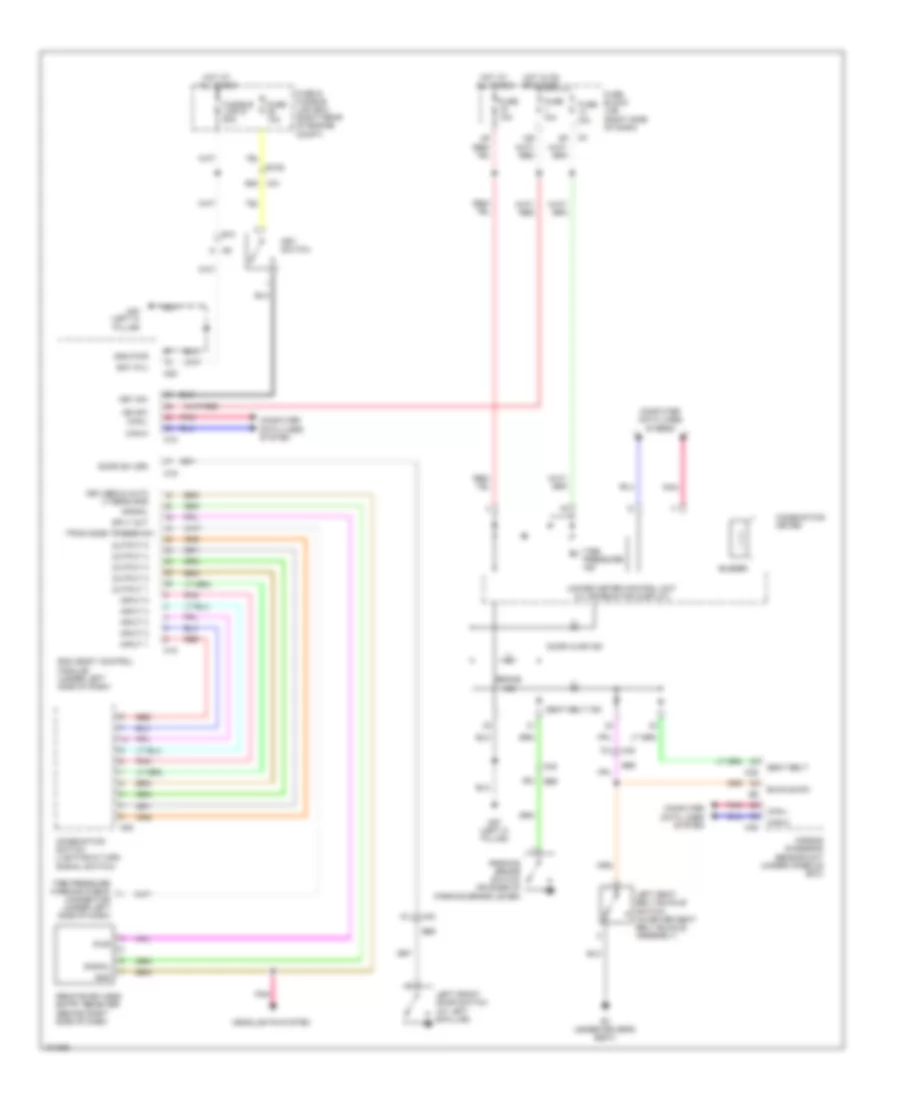
AIR CONDITIONING
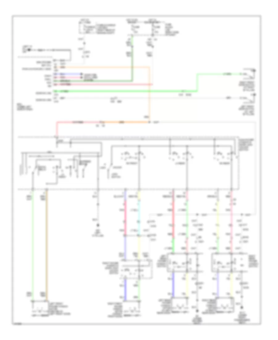
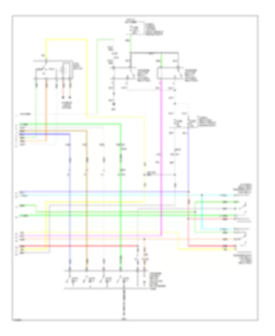
Manual A/C Wiring Diagram, Early Production for Nissan Xterra X 2013
 https://portal-diagnostov.com/license.html
Automotive Electricians Portal FZCO
Automotive Electricians Portal FZCO
https://portal-diagnostov.com/license.html
https://portal-diagnostov.com/license.html
Automotive Electricians Portal FZCO
Automotive Electricians Portal FZCO
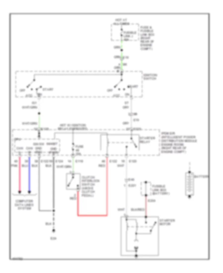
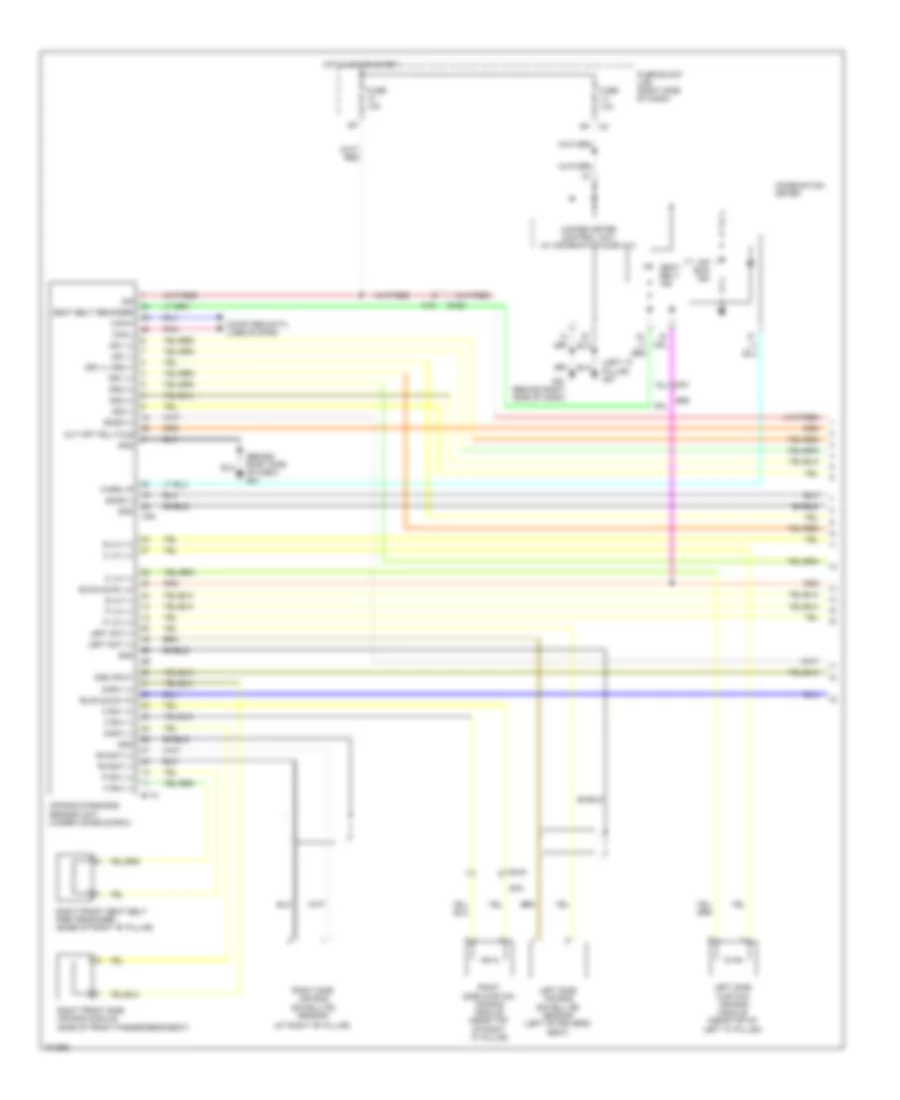
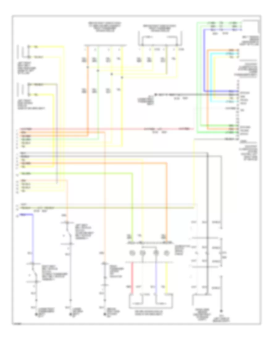
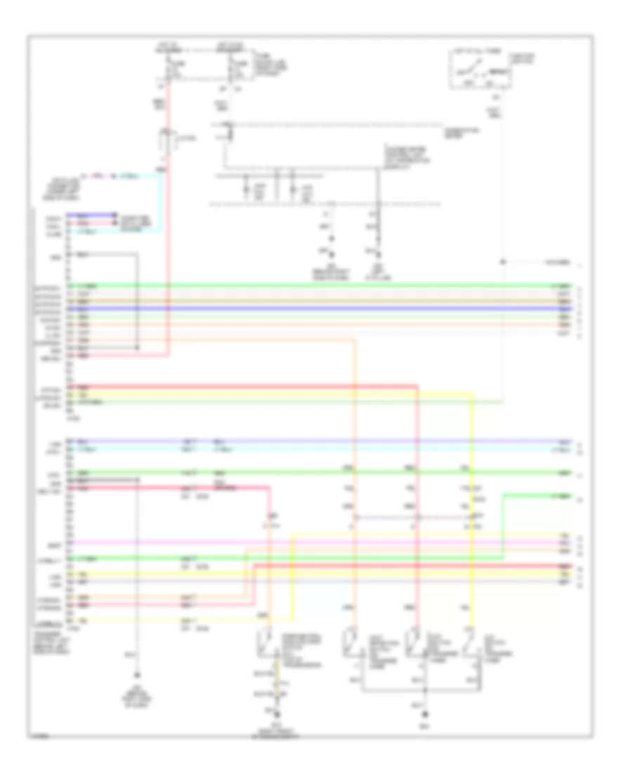
List of elements for Manual A/C Wiring Diagram, Early Production for Nissan Xterra X 2013:
- (behind right side of dash) m61
- 60g
- 75g
- 80g
- A/c compressor (left front of engine)
- A/c relay
- A/c request
- Air mix door motor (behind center of dash)
- Aircon sw
- Avcc
- Batt
- Bcm (under left side of dash)
- Blend feed back
- Blower fan sw
- Can-h
- Can-l
- Computer
- Computer data lines system
- Cooling fan hi relay
- Cooling fan lo relay
- Cooling fan motor (front of engine compt)
- Cpu
- Data lines
- Defogger system
- Dr blend ccw
- Dr blend cw
- E119
- E120
- E122
- E124
- E15 (right front of engine compt)
- E152
- E16
- E24
- Ecm (right rear of engine compt)
- Engine controls system
- Engine coolant temperature sensor (rear of engine)
- F14
- F32
- F57
- Fan on
- Fr blower monitor
- Front air control (behind center of dash)
- Front blower motor (behind glove box, on intake unit)
- Front blower motor relay (right rear of engine compt)
- Fuse & fusible link box (right rear of engine compt)
- Fuse 10a
- Fuse 15a
- Fuse 20a
- Fuse block (j/b) (right side of dash)
- Fusible link i 40a
- Gnd
- Gnd (power)
- Gnd (sig)
- Gnd-a
- Gnd-a pdrress
- Hot at all times
- Hot in on
- Hot in on or start
- Ign
- Ignition relay
- Ill+
- Ill-
- Intake door motor (behind right side of dash, on intake unit)
- Intake sensor
- Intake sensor (behind right side of dash)
- Interior lights
- Ipdm e/r (right rear of engine compt)
- M18
- M31
- M61 (behind right side of dash)
- Mode (gnd)
- Mode ccw
- Mode cw
- Mode door motor (behind center of dash)
- Mode feed back
- Pd press
- Pnk
- Recirc door ccw
- Recirc door cw
- Red
- Refrigerant pressure sensor (front of engine compt)
- Rr def status
- Rr defogger request
- Sens rtn
- System
- V ref actr (5v)
- Variable blower control (right side of dash)
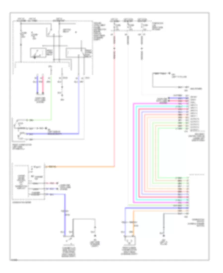
Manual A/C Wiring Diagram, Late Production for Nissan Xterra X 2013
List of elements for Manual A/C Wiring Diagram, Late Production for Nissan Xterra X 2013:
- (behind right side of dash, on intake unit)
- (front of engine compt) cooling fan motor
- (right side of dash)
- (under left side of dash) bcm
- 5n m3
- 60g
- 75g
- 80g
- 8p m4
- A/c compressor (left front of engine)
- A/c relay
- A/c request
- Aircon sw
- Avcc
- Bat
- Blend feed back
- Blower monitor
- Can-h
- Can-l
- Computer data lines system
- Cooling fan high relay
- Cooling fan low relay
- Cpu
- Defogger system
- Dr blend ccw
- Dr blend cw
- E119
- E120
- E122
- E124
- E15 (right front of engine compt)
- E152
- E16
- E24
- Ecm (right rear of engine compt)
- Engine controls system
- Engine coolant temperature sensor (rear of engine)
- F14
- F32
- F57
- Fan sw
- Front air control (behind center of dash)
- Front air mix door motor (behind center of dash)
- Front blower motor (behind glove box, on intake unit)
- Front blower motor relay (right rear of engine compt)
- Front blower motor resistor (behind right side of dash)
- Front blower switch
- Fuse & fusible link box (right rear of engine compt)
- Fuse 10a
- Fuse 15a
- Fuse block (j/b)
- Fusible link i 40a
- Gnd
- Gnd-a
- Gnd-a pdrress
- Hot at all times
- Hot in on
- Hot in on or start
- Ign
- Ignition relay
- Ill (+)
- Ill (-)
- Intake door motor
- Intake sensor
- Intake sensor (behind right side of dash)
- Interior lights system
- Ipdm e/r (right rear of engine compt)
- M18
- M31
- M61 (behind right side of dash)
- Mode ccw
- Mode cw
- Mode door motor (behind center of dash)
- Mode feed back
- Mode gnd
- Off
- Pdpres
- Pnk
- Recirc door ccw
- Recirc door cw
- Red
- Refrigerant pressure sensor (front of engine compt)
- Rr def request
- Rr def status
- Sens return
- V ref actr (5v)
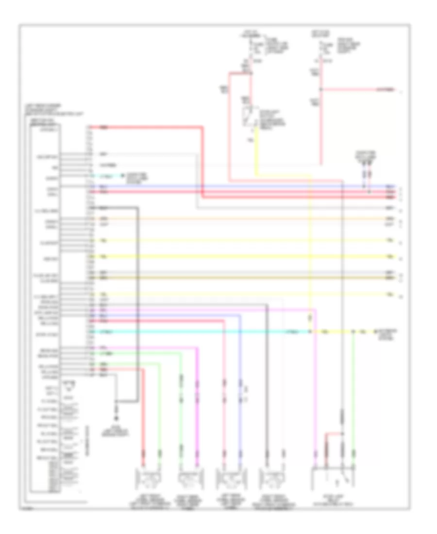
ANTI-LOCK BRAKES
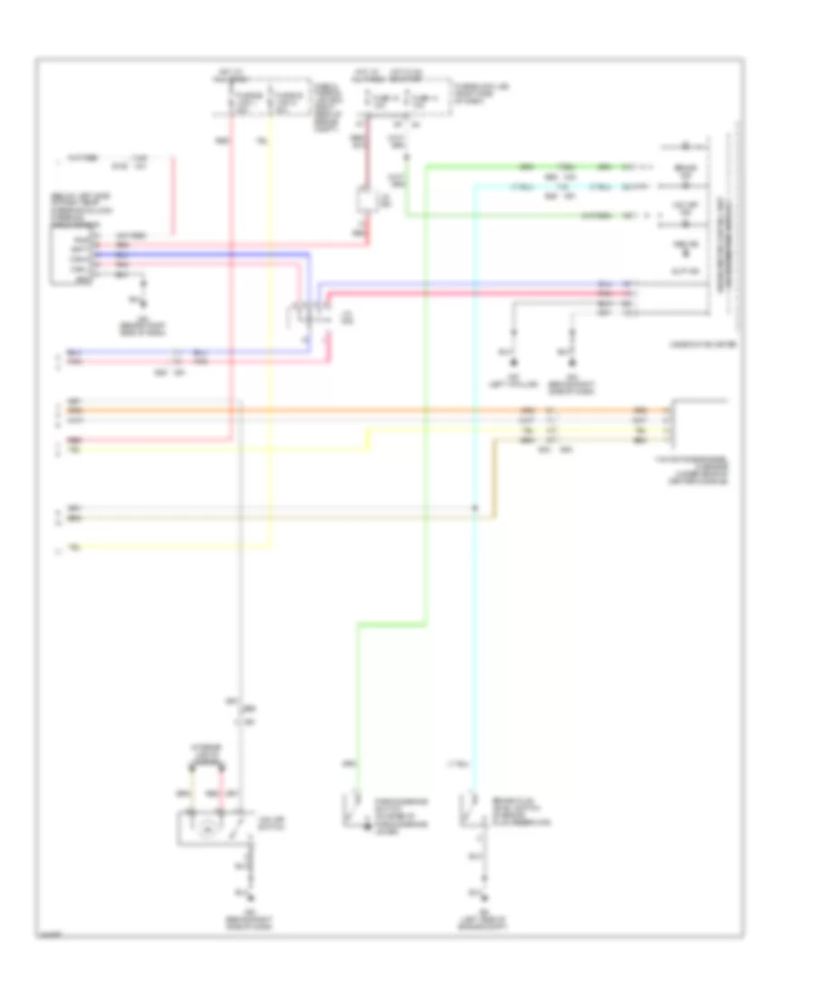
Anti-lock Brakes Wiring Diagram, with Traction Control & Stability Assist with Hill Assist (1 of 2) for Nissan Xterra X 2013
List of elements for Anti-lock Brakes Wiring Diagram, with Traction Control & Stability Assist with Hill Assist (1 of 2) for Nissan Xterra X 2013:
- (left rear corner of engine compt) abs actuator & electric unit
- 15c
- 16c
- 17c
- 18c
- Abs/tcs/vdc control unit
- Can-h
- Can-l
- Can2-h
- Can2-l
- Clus gnd
- Clus sup
- Computer data lines system
- Diag-k
- E119
- E126 (left side of engine compt)
- E160
- E41
- Exterior lights system
- Fl in sol
- Fl out sol
- Fluid lev sw
- Fr in sol
- Fr lh pwr
- Fr lh sig
- Fr out sol
- Fr rh pwr
- Fr rh sig
- Fuse 10a
- Fuse block (j/b) (right side of dash)
- Hdc sw
- Hot at all times
- Hot in on or start
- Hsv2 (mc2) hsv1 (mc1) usv2 (mc2) usv1 (mc1)
- Ign
- Ipdm e/r (right rear of engine compt)
- Left front wheel sensor (left front steering knuckle assembly)
- Left rear wheel sensor (left rear wheel)
- Mot (+)
- Mot (-)
- Motor
- Mtr gnd
- Mtr sply
- Pnk
- Red
- Right front wheel sensor (right front steering knuckle assembly)
- Right rear wheel sensor (right rear wheel)
- Rl in sol
- Rl out sol
- Rr in sol
- Rr lh pwr
- Rr lh sig
- Rr out sol
- Rr rh pwr
- Rr rh sig
- Solenoid valve
- Stop lamp relay (in fuse & relay box)
- Stop lp sw
- Stoplight switch (on bracket, above brake pedal)
- Stp lamp on
- Vdc off sw
- Vlv ecu gnd
- Vlv ecu sply
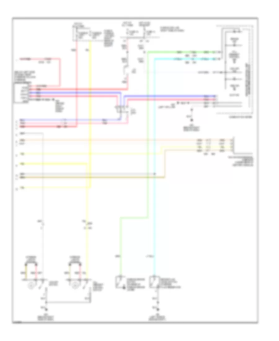
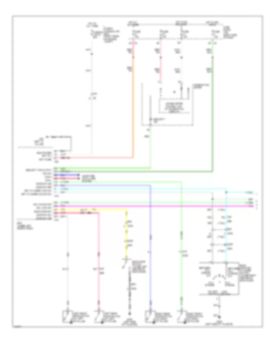
Anti-lock Brakes Wiring Diagram, with Traction Control & Stability Assist with Hill Assist (2 of 2) for Nissan Xterra X 2013
List of elements for Anti-lock Brakes Wiring Diagram, with Traction Control & Stability Assist with Hill Assist (2 of 2) for Nissan Xterra X 2013:
- (below left side of dash, near steering column)
- (w/ information display) unified meter control unit
- 44g
- 68j
- Abs ind
- B40
- B69
- Batt
- Brake fluid level switch (in brake fluid reservoir)
- Brake ind
- Can-h
- Can-l
- Combination meter
- E26
- E34
- E9 (left side of engine compt)
- Fuse & fusible link box (right rear of engine compt)
- Fuse 14 10a
- Fuse 18 10a
- Fuse block (j/b) (right side of dash)
- Fusible link i 30a
- Fusible link n 40a
- Gnd
- Hill descent control ind
- Hill descent control switch
- Hot at all times
- Hot in on or start
- Interior lights system
- J/c m02
- J/c m03
- M31 e152
- M40
- M57 (left a-pillar)
- M61 (behind right side of dash)
- M91
- Parking brake switch (on base of parking brake lever)
- Pnk
- Pwr
- Red
- Slip ind
- Steering angle sensor
- Vdc off ind
- Vdc off switch
- Yaw rate/side/decel g-sensor (under rear of center console)
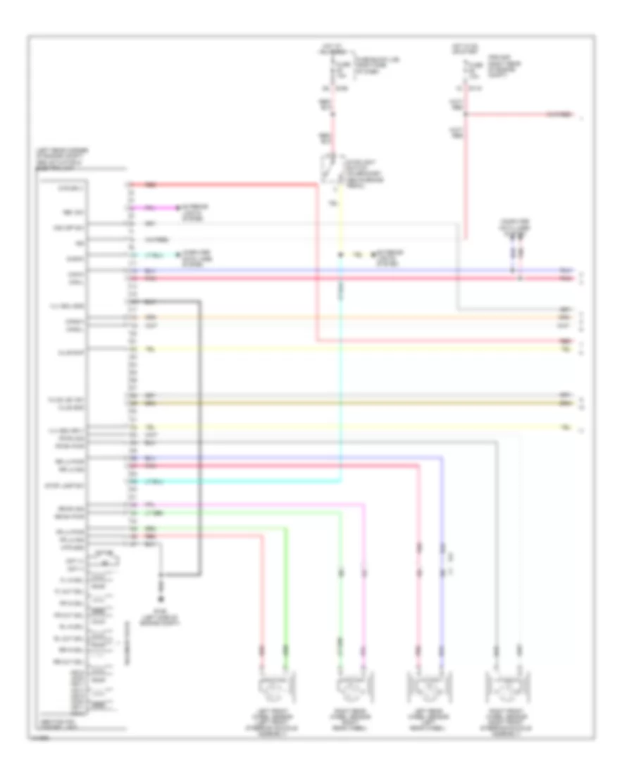
Anti-lock Brakes Wiring Diagram, with Traction Control & Stability Assist, without Hill Assist (1 of 2) for Nissan Xterra X 2013
List of elements for Anti-lock Brakes Wiring Diagram, with Traction Control & Stability Assist, without Hill Assist (1 of 2) for Nissan Xterra X 2013:
- (left rear corner of engine compt) abs actuator & electric unit
- 15c
- 16c
- 17c
- 18c
- Abs/tcs/vdc control unit
- Can-h
- Can-l
- Can2-h
- Can2-l
- Clus gnd
- Clus sup
- Computer data lines system
- Diag-k
- E119
- E126 (left side of engine compt)
- E160
- E41
- Exterior lights system
- Fl in sol
- Fl out sol
- Fluid lev sw
- Fr in sol
- Fr lh pwr
- Fr lh sig
- Fr out sol
- Fr rh pwr
- Fr rh sig
- Fuse 10a
- Fuse block (j/b) (right side of dash)
- Hot at all times
- Hot in on or start
- Hsv2 (mc2) hsv1 (mc1) usv2 (mc2) usv1 (mc1)
- Ign
- Ipdm e/r (right rear of engine compt)
- Left front wheel sensor (left front steering knuckle assembly)
- Left rear wheel sensor (left rear wheel)
- Mot (+)
- Mot (-)
- Motor
- Mtr gnd
- Mtr sply
- Pnk
- Red
- Rev sw
- Right front wheel sensor (right front steering knuckle assembly)
- Right rear wheel sensor (right rear wheel)
- Rl in sol
- Rl out sol
- Rr in sol
- Rr lh pwr
- Rr lh sig
- Rr out sol
- Rr rh pwr
- Rr rh sig
- Solenoid valve
- Stop lamp sw
- Stoplight switch (on bracket, above brake pedal)
- Vdc off sw
- Vlv ecu gnd
- Vlv ecu sply
Anti-lock Brakes Wiring Diagram, with Traction Control & Stability Assist, without Hill Assist (2 of 2) for Nissan Xterra X 2013
List of elements for Anti-lock Brakes Wiring Diagram, with Traction Control & Stability Assist, without Hill Assist (2 of 2) for Nissan Xterra X 2013:
- (below left side of dash, near steering column) steering angle sensor
- 44g
- 68j
- Abs ind
- B40
- B69
- Batt
- Brake fluid level switch (in brake fluid reservoir)
- Brake ind
- Can-h
- Can-l
- Combination meter
- E152 m31
- E26
- E34
- E9 (left side of engine compt)
- Fuse & fusible link box (right rear of engine compt)
- Fuse 14 10a
- Fuse 18 10a
- Fuse block (j/b) (right side of dash)
- Fusible link l 30a
- Fusible link n 40a
- Gnd
- Hot at all times
- Hot in on or start
- Interior lights system
- J/c m02
- J/c m03
- M40
- M57 (left a-pillar)
- M61 (behind right side of dash)
- M91
- M91 e26
- Parking brake switch (on base of parking brake lever)
- Pnk
- Pwr
- Red
- Slip ind
- Unified meter control unit (w/ information display)
- Vdc off ind
- Vdc off switch
- Yaw rate/side/decel g sensor (under rear of center console)
ANTI-THEFT
Forced Entry Wiring Diagram (1 of 2) for Nissan Xterra X 2013
List of elements for Forced Entry Wiring Diagram (1 of 2) for Nissan Xterra X 2013:
- 4p m4
- 52j
- 57j
- 61j
- Acc sw
- B162
- B48
- B69
- Back door key cylinder switch (lower right center of back door)
- Back door sw
- Back door switch (lower left center of back door)
- Bat (f/l)
- Bat (fuse)
- Bcm (under left side of dash)
- Between full stroke & n
- Can-h
- Can-l
- Cdl lock sw
- Cdl unlock sw
- Combination meter
- Computer data lines system
- D402
- D405
- D406 (left side of tailgate)
- D501
- Door sw (as)
- Door sw (dr)
- Door sw (rl)
- Door sw (rr)
- E10
- Full stroke
- Fuse & fusible link box (right rear of engine compt)
- Fuse 10a
- Fuse block (j/b) (right side of dash)
- Fusible link g 50a
- Gnd (power)
- Hot at all times
- Hot in acc or on
- Hot in on or start
- Key cylinder lock sw
- Key cylinder unlock sw
- Left front door switch (at left "b" pillar)
- Left rear door switch (at left "c" pillar)
- Lock switch
- M16
- M18
- M19
- M20
- M3 4n
- M40
- M40 53j
- M40 60j
- M57 (left "a" pillar)
- Pnk
- Right front door switch (at right "b" pillar)
- Right rear door switch (at right "c" pillar)
- Security ind
- Security ind output
- Un lock switch
- Unified meter control unit (w/ information display)
Forced Entry Wiring Diagram (2 of 2) for Nissan Xterra X 2013
List of elements for Forced Entry Wiring Diagram (2 of 2) for Nissan Xterra X 2013:
- +ig
- Anti theft horn
- Between full stroke & n
- Can-h
- Can-l
- Computer data lines system
- Cpu
- D101
- D102
- D150
- D151
- D152
- D153
- E122
- E123
- E124
- E24
- E9 (left side of engine compt)
- Full stroke
- Fuse & fusible link box (right rear of engine compt)
- Fuse 10a
- Fuse 15a
- Fuse 20a
- Gnd
- Gnd (pwr)
- Gnd (sig)
- H/lp hi
- H/lp lo
- Headlamp high relay
- Headlamp low relay
- Headlights system
- Horn (left front of engine compt)
- Horn relay (in fuse & fusible link box)
- Horns system
- Hot at all times
- Hot in on or start
- Ignition relay
- Ipdm e/r (right rear of engine compt)
- Left front door lock assembly (key cylinder switch)
- Lock
- Lock switch
- M57 (left "a" pillar)
- M74
- M75
- M79 (behind right side of dash)
- Main power window & door lock/ unlock switch
- Pnk
- Red
- Right power window & door lock/ unlock switch
- Unlock
- Unlock switch
- W/ dual tone horn
Immobilizer Wiring Diagram for Nissan Xterra X 2013
List of elements for Immobilizer Wiring Diagram for Nissan Xterra X 2013:
- +ig
- 15p
- Anti theft horn
- Bat (f/l)
- Bat (fuse)
- Bcm (under left side of dash)
- Can h
- Can l
- Can-h
- Can-l
- Clock
- Combination meter
- Computer data lines system
- Cpu
- E10
- E121
- E122
- E124
- E152
- E24
- E9 (left side of engine compt)
- Fuse & fusible link box (right rear of engine compt)
- Fuse 10a
- Fuse 15a
- Fuse 20a
- Fuse block (j/b) (right side of dash)
- Fusible link g 50a
- Gnd
- Gnd (power)
- Gnd (pwr)
- Gnd (sig)
- H/lp hi
- H/lp lo
- Headlights system
- Horn (left front of engine compt)
- Horn relay (in fuse & fusible link box)
- Horns system
- Hot at all times
- Hot in on or start
- Ign sw
- Ignition relay
- Immob ant sig (clock)
- Immob ant sig (rx, tx)
- Ipdm e/r (right rear of engine compt)
- M18
- M20
- M31
- M57 (left 'a' pillar)
- Nats antenna amplifier (behind center of dash)
- Pnk
- Red
- Rx,tx
- Security ind
- Security ind output
- Unified meter control unit (w/ information display)
- Vb (12v)
- W/ dual tone horn
BODY CONTROL MODULES
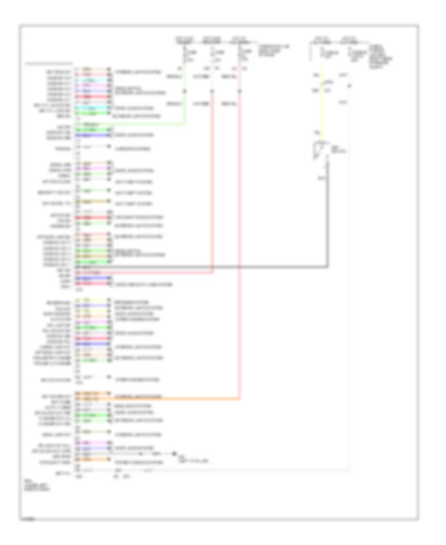
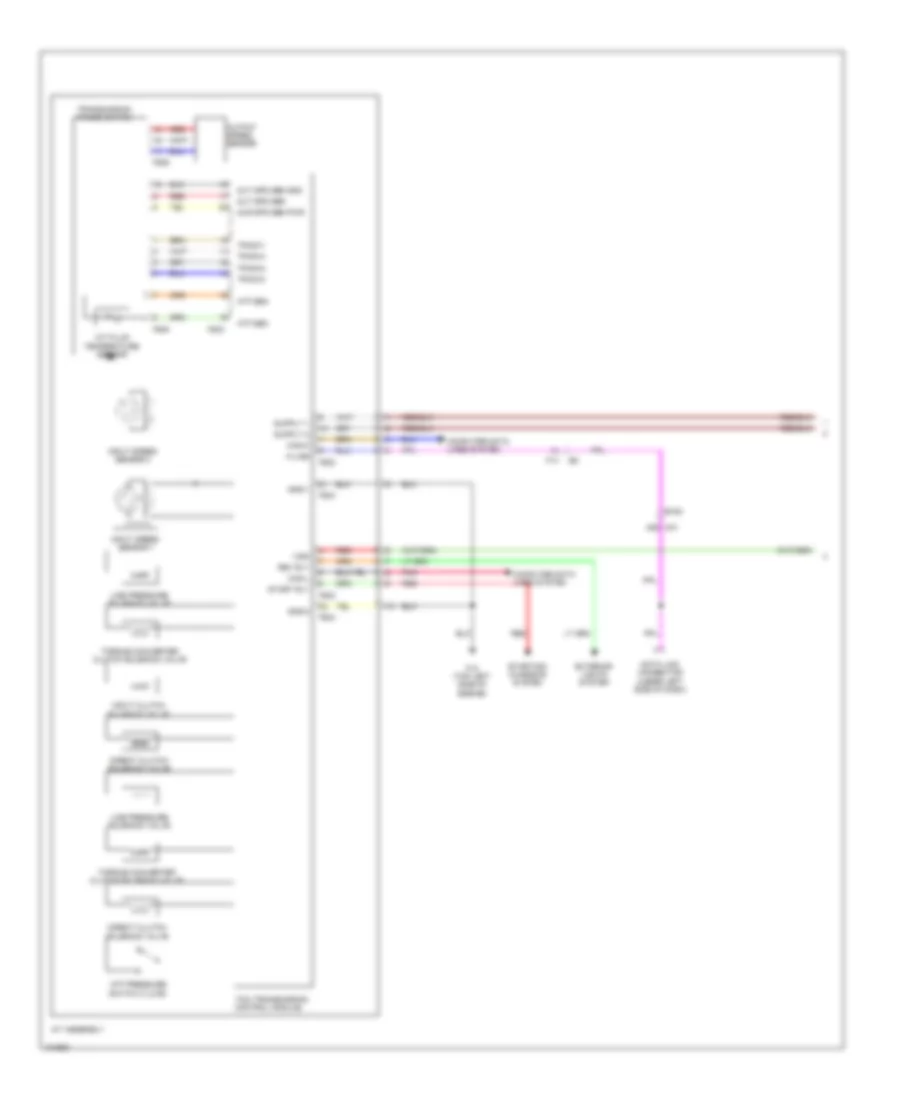
Body Control Modules Wiring Diagram for Nissan Xterra X 2013
List of elements for Body Control Modules Wiring Diagram for Nissan Xterra X 2013:
- 15p
- 55g
- Acc sw
- Air con sw
- Air conditioning system
- Ant sig (clock)
- Ant sig (rx, tx)
- Anti-theft system
- Auto lt sens
- Auto stop
- Back door sw
- Bat (f/l)
- Bat (fuse)
- Bat saver out
- Bcm (under left side of dash)
- Brk sw
- Can-h
- Can-l
- Cargo lamp out
- Cdl lock sw
- Cdl unlock sw
- Comb sw in 1
- Comb sw in 2
- Comb sw in 3
- Comb sw in 4
- Comb sw in 5
- Comb sw out 1
- Comb sw out 2
- Comb sw out 3
- Comb sw out 4
- Comb sw out 5
- Computer data lines system
- Defogger system
- Door locks system
- Door sw (as)
- Door sw (dr)
- Door sw (rl)
- Door sw (rr)
- Dr lock out (all)
- Dr unlock out (dr)
- Dr unlock out (otr)
- E10
- E152
- Exterior lights system
- Fan sw
- Flasher out (lh)
- Flasher out (rh)
- Fuse & fusible link box (right rear of engine compt)
- Fuse 10a
- Fuse 25 10a
- Fuse block (j/b) (right side of dash)
- Fusible link g 50a
- Gnd (pwr)
- Hazard sw
- Headlights & exterior lights systems
- Headlights system
- Hot at all times
- Hot in on or acc
- Hot in on or start
- Ign sw
- Interior lights system
- Key cyl lock sw
- Key cyl unlock sw
- Key ring out
- Key sw
- Key switch
- M18
- M19
- M20
- M31
- M57 (left "a" pillar)
- Off road lamp out
- Off road lamp sw
- Pca out
- Pnk
- Power windows system
- Pwr suply (rap)
- Red
- Room lamp out
- Rr defog sw
- Rr wip o/p (mtr)
- Security ind out
- Signal
- Signal gnd
- Signal pwr
- Tpms sw
- Trailer lh flasher
- Trailer rh flasher
- Warning systems
- Wiper/washer system
COMPUTER DATA LINES
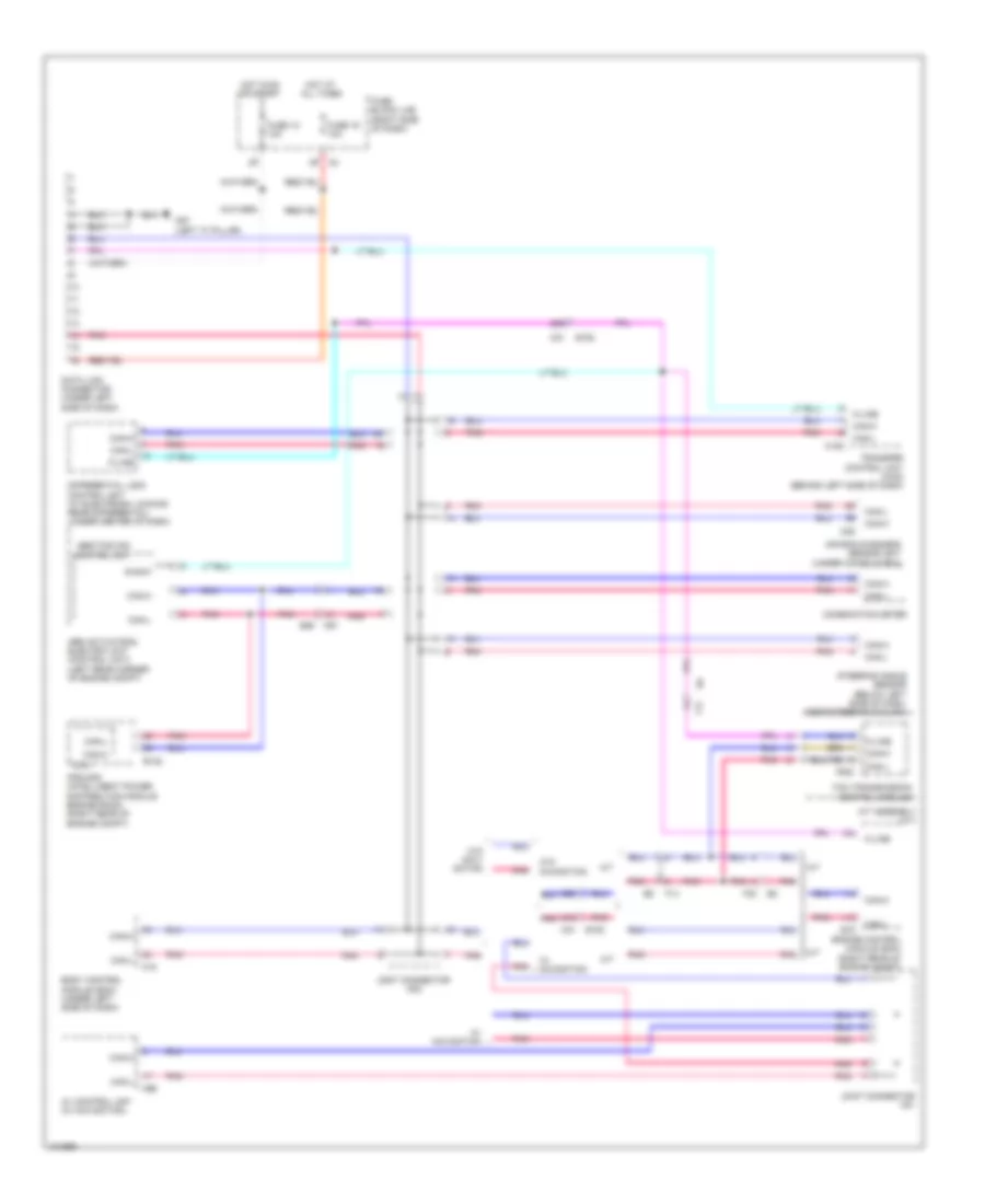
Computer Data Lines Wiring Diagram for Nissan Xterra X 2013
List of elements for Computer Data Lines Wiring Diagram for Nissan Xterra X 2013:
- 48g
- 51g
- 52g
- 8p m4
- A/t
- A/t assembly (a/t)
- Abs actuator & electric unit (control unit) (left rear corner of engine compt)
- Abs/tcs/vdc control unit
- Air bag diagnosis sensor unit (under console box)
- Av control unit (w/ navigation)
- Body control module (bcm) (under left side of dash)
- Can-h
- Can-l
- Combination meter
- Cpu
- Data link connector (under left side of dash)
- Diag-k
- Differential lock control unit (w/ electronic locking rear differential) (under center of dash)
- E122
- E152
- E16
- E26
- Engine control module (ecm) (right rear of engine compt)
- F14
- F32
- F502
- Fuse 12 10a
- Fuse 19 10a
- Fuse block (j/b) (right side of dash)
- Hot at all times
- Hot in on or start
- Ipdm e/r (intelligent power distribution module engine room) (right rear of engine compt)
- Joint connector m01
- Joint connector m02
- K-line
- M/t
- M152
- M18
- M31
- M31 e152
- M35
- M57 (left "a" pillar)
- M91
- M96
- Pnk
- Steering angle sensor (below left side of dash, near steering column)
- Tcm (transmission control module)
- Transfer control unit (4wd) (behind left side of dash)
- W/ navigation
- W/o navi- gation
- W/o navigation
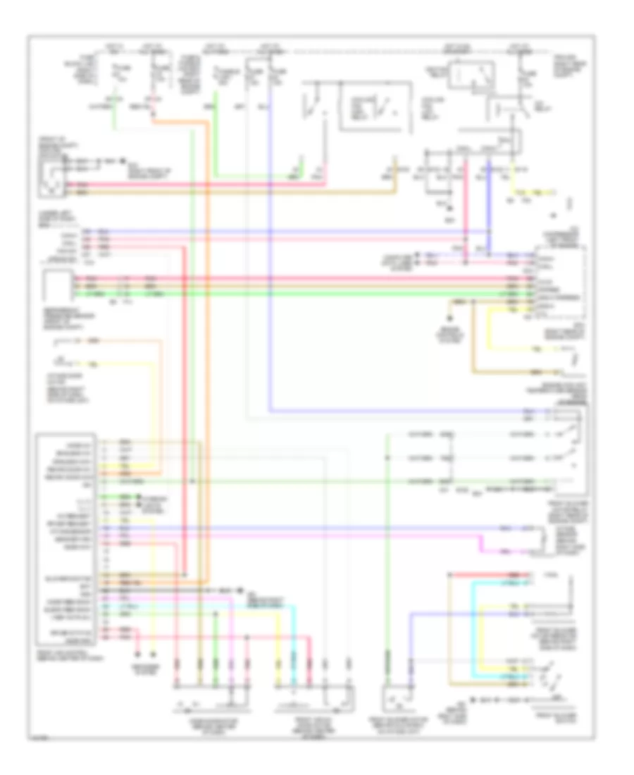
COOLING FAN
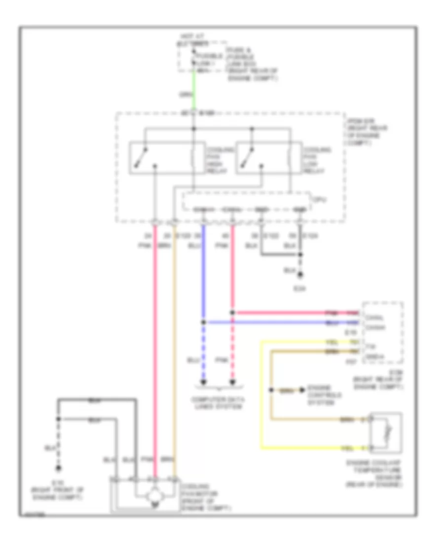
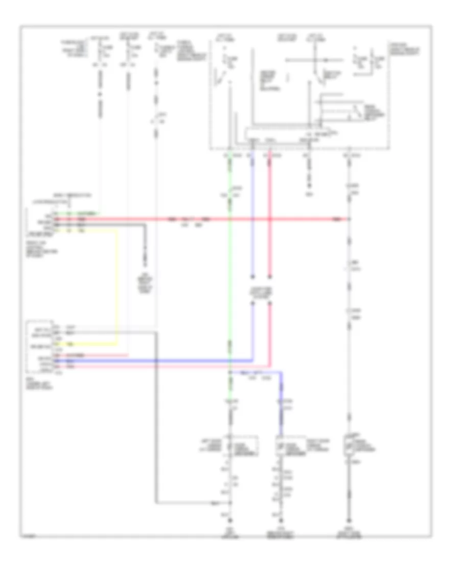
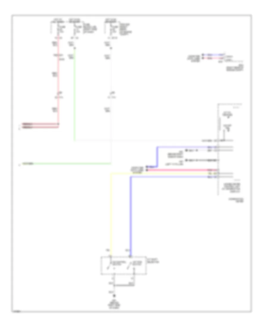
Cooling Fan Wiring Diagram for Nissan Xterra X 2013
List of elements for Cooling Fan Wiring Diagram for Nissan Xterra X 2013:
- Can-h
- Can-l
- Computer data lines system
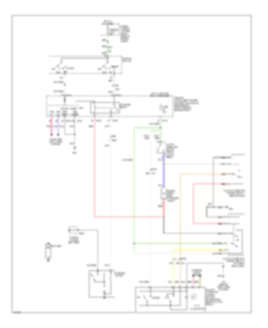
- Cooling fan high relay
- Cooling fan low relay
- Cooling fan motor (front of engine compt)
- Cpu
- E120
- E122
- E124
- E15 (right front of engine compt)
- E16
- E24
- Ecm (right rear of engine compt)
- Engine controls system
- Engine coolant temperature sensor (rear of engine)
- F57
- Fuse & fusible link box (right rear of engine compt)
- Fusible link i 40a
- Gnd
- Gnd-a
- Hot at all times
- Ipdm e/r (right rear of engine compt)
- Pnk
CRUISE CONTROL
Cruise Control Wiring Diagram for Nissan Xterra X 2013
List of elements for Cruise Control Wiring Diagram for Nissan Xterra X 2013:
- 42g
- 43g
- A/t
- A/t assembly
- Accelerator pedal position (app) sensor (under left side of dash)
- Aps1
- Aps2
- Ascd steering switch
- Ascd sw
- Avcc
- Avcc 1
- Avcc2
- Bncsw
- Brake
- Brake pedal position switch
- Can-h
- Can-l
- Cancel switch
- Close
- Clutch pedal position switch
- Combination meter
- Combination switch (spiral cable)
- Computer data lines system
- Cruise ind
- E119
- E122
- E16
- E160
- E2 f32
- E24
- E5 f14
- Ecm (right rear of engine compt)
- Electric throttle control actuator (on throttle body)
- F502
- F503
- F505
- F506
- F54
- Fuse 12 10a
- Fuse 14 10a
- Fuse 19 10a
- Fuse 20 10a
- Fuse 20a
- Fuse block (j/b) (right side of dash)
- Gnd
- Gnd-a
- Gnd-a2
- Hot at all times
- Hot in on or start
- Input speed sensor 1
- Input speed sensor 2
- Ipdm e/r (intelligent power distribution module engine room) (right rear of engine compt)
- M/t
- M102
- M30
- M31 e152
- M57 (left "a" pillar)
- Mot rly
- Motor 1
- Motor 2
- Nca
- On/off (main) switch
- Open
- Out spd sen gnd
- Out spd sens power out spd sen
- Output speed sensor
- Pnk
- Red
- Resume/ accel switch
- Sensor 1
- Sensor 2
- Set ind
- Set/ coast switch
- Stop light switch (a/t: on bracket, above brake pedal)
- Throttle control motor
- Throttle control motor relay
- Throttle position sensor
- Tps 1
- Tps 2
- Transmission control module
- Transmission range switch
- Unified meter control unit (w/ information display)
- V mot
DEFOGGERS
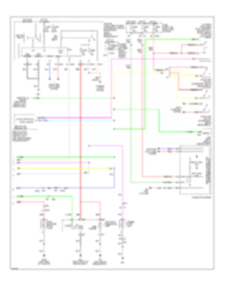
Defoggers Wiring Diagram for Nissan Xterra X 2013
List of elements for Defoggers Wiring Diagram for Nissan Xterra X 2013:
- +ig
- 15p
- 74g
- 79j
- B42
- B50
- B69
- Bat (f/l)
- Bcm (under left side of dash)
- Can-h
- Can-l
- Computer data lines system
- Cpu
- D101
- D152
- D153
- D409
- D410
- D603 (right side of tailgate)
- D604
- D650
- D651
- Door mirror defogger
- E10
- E120
- E122
- E124
- E152
- E24
- E36
- Early production
- Front air control (behind center of dash)
- Fuse & fusible link box (right rear of engine compt)
- Fuse 10a
- Fuse 15a
- Fuse block (j/b) (right side of dash)
- Fusible link g 50a
- Gnd
- Gnd (pwr)
- Heated mirror relay (if equipped)
- Hot at all times
- Hot in on
- Hot in on or start
- Ign
- Ign sw
- Ignition relay
- Ipdm e/r (right rear of engine compt)
- Late production
- Left door mirror (at mirror)
- M18
- M19
- M20
- M31
- M40
- M57 (left a-pillar)
- M61 (behind right side of dash)
- M75
- M79 (behind right side of dash)
- Pnk
- Rear window defogger
- Rear window defogger relay
- Red
- Right door mirror (at mirror)
- Rr def
- Rr def req
- Rr def sw
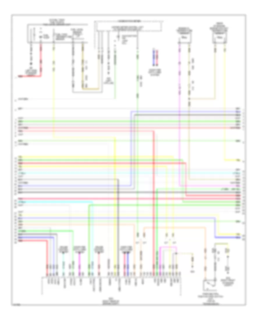
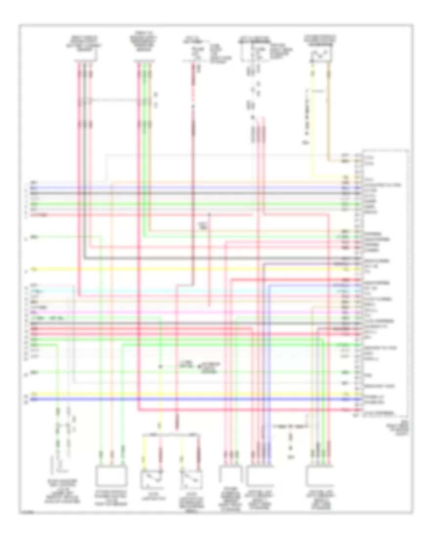
ENGINE PERFORMANCE
4.0L
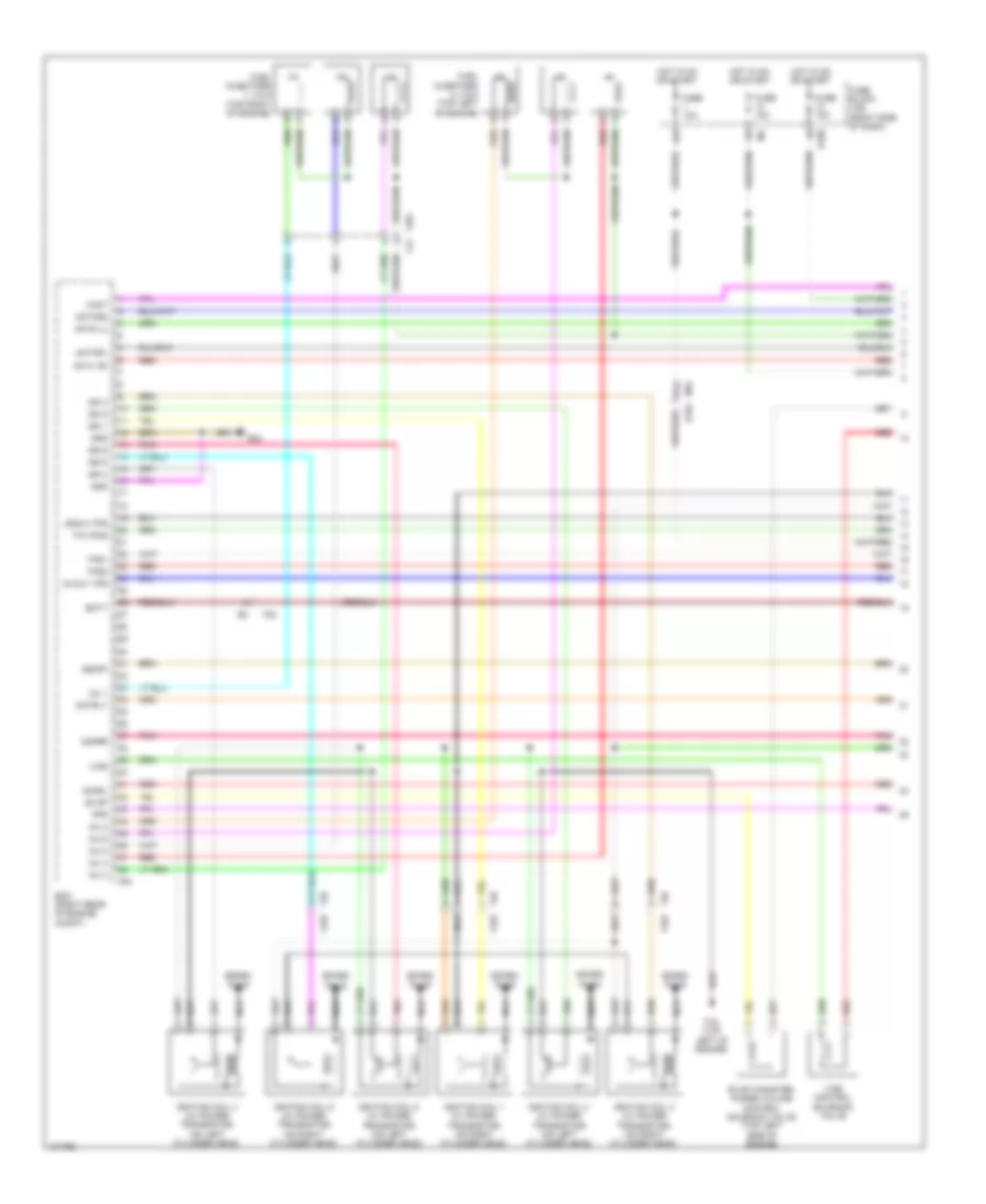
4.0L, Engine Performance Wiring Diagram (1 of 5) for Nissan Xterra X 2013
List of elements for 4.0L, Engine Performance Wiring Diagram (1 of 5) for Nissan Xterra X 2013:
- 15p
- 41g
- Af-h1 (r)
- Af-h2 (l)
- Avcc1 tps
- Batt
- E160
- E24
- Ecm (right rear of engine compt)
- Evap
- Evap canister purge volume control solenoid valve (top left side of engine)
- F16 (top left of engine)
- F201 f44
- F26 f225
- F32
- F54
- Fpr
- Fuel injectors 1, 3 & 5 (top right of engine)
- Fuel injectors 2, 4 & 6 (top left of engine)
- Fuse 10a
- Fuse block (j/b) (right side of dash)
- Gnd
- Gnd-a tps
- Hot in on or start
- Ign 1
- Ign 2
- Ign 3
- Ign 4
- Ign 5
- Ign 6
- Ignition coil 1 (w/ power transistor) (on right cylinder head)
- Ignition coil 2 (w/ power transistor) (on left cylinder head)
- Ignition coil 3 (w/ power transistor) (on right cylinder head)
- Ignition coil 4 (w/ power transistor) (on left cylinder head)
- Ignition coil 5 (w/ power transistor) (on right cylinder head)
- Ignition coil 6 (w/ power transistor) (on left cylinder head)
- Inj 1
- Inj 2
- Inj 3
- Inj 4
- Inj 5
- Inj 6
- M31 e152
- Motor1
- Motor2
- Motrly
- Nca
- O2hrl
- O2hrr
- Pnk
- Red
- Spark plug
- Ssoff
- Tcv-pos
- Tps1
- Tps2
- Vias
- Vias control solenoid valve
- Vmot
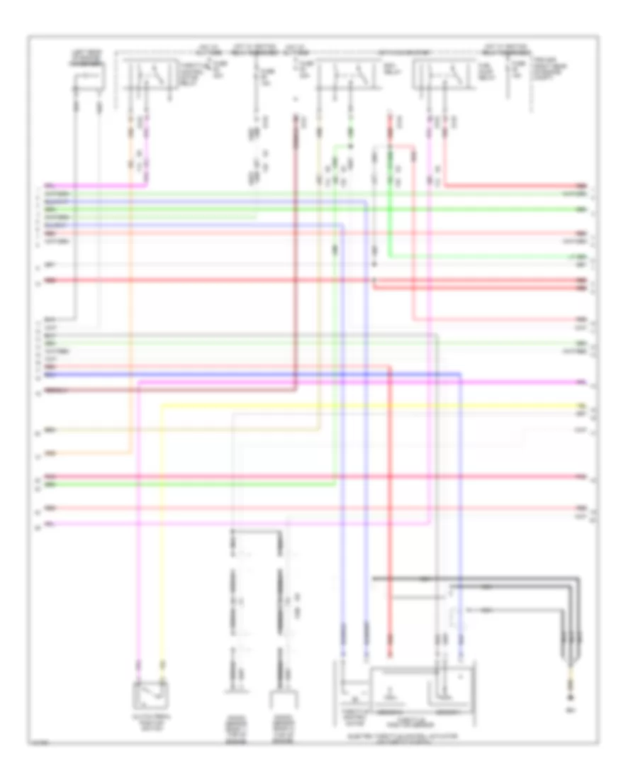
4.0L, Engine Performance Wiring Diagram (2 of 5) for Nissan Xterra X 2013
List of elements for 4.0L, Engine Performance Wiring Diagram (2 of 5) for Nissan Xterra X 2013:
- (left rear of engine) condenser 1
- Clutch pedal position switch
- E119
- E121
- E122
- E24
- Ecm relay
- Electric throttle control actuator (on throttle body)
- F14
- F250
- F32
- F67
- Fuel pump relay
- Fuse 15a
- Fuse 20a
- Hot at all times
- Hot in on or start
- Hot w/ ignition relay energized
- Ipdm e/r (right rear of engine compt)
- Knock sensor (bank 1) (top of engine)
- Knock sensor (bank 2) (top of engine)
- Nca
- Pnk
- Red
- Sensor 1
- Sensor 2
- Shield
- Throttle control motor
- Throttle control motor relay
- Throttle position sensor
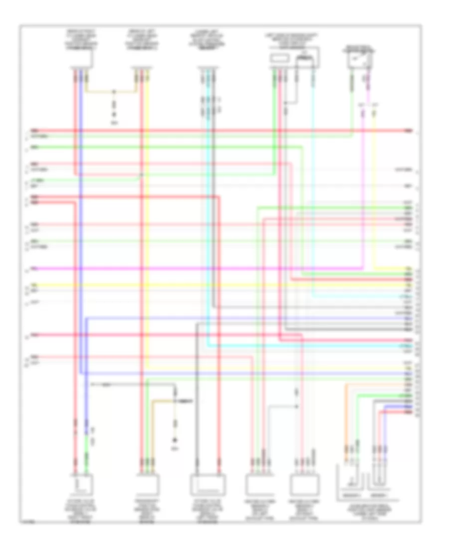
4.0L, Engine Performance Wiring Diagram (3 of 5) for Nissan Xterra X 2013
List of elements for 4.0L, Engine Performance Wiring Diagram (3 of 5) for Nissan Xterra X 2013:
- (left side of engine compt, near air intake box) mass airflow (maf) sensor
- (rear of left cylinder head) camshaft position sensor (phase) (bank 2)
- (rear of right cylinder head) camshaft position sensor (phase) (bank 1)
- (under left rear of vehicle) evap control system pressure sensor
- 10c
- 11c
- 12c
- A/t
- Accelerator pedal position (app) sensor (under left side of dash)
- Brake pedal position switch
- C1 e41
- Crankshaft position sensor (pos) (right rear of engine)
- E24
- F225
- F26
- Heated oxygen sensor 2 (bank 1) (on right exhaust pipe)
- Heated oxygen sensor 2 (bank 2) (on left exhaust pipe)
- Iat sensor
- Intake valve timing control solenoid valve (bank 1) (right front of engine)
- Intake valve timing control solenoid valve (bank 2) (left front of engine)
- M/t
- Nca
- Pnk
- Red
- Sensor 1
- Sensor 2
4.0L, Engine Performance Wiring Diagram (4 of 5) for Nissan Xterra X 2013
List of elements for 4.0L, Engine Performance Wiring Diagram (4 of 5) for Nissan Xterra X 2013:
- (in fuel tank) fuel pump & fuel level sensor unit
- (rear of engine) engine coolant temperature sensor
- 13c
- 14c
- 28c
- 56g
- 66g
- 67g
- A/t
- Aps1
- Aps2
- Ascd sw
- Avcc
- Avcc2
- Avcc2-tprs
- Bncsw
- Brake
- Can-h
- Can-l
- Cdcv
- Combination meter
- Computer data lines system
- Cruise control system
- E15 (right front of engine compt)
- E152
- E16
- E201
- E24
- E40
- E41
- E9 (left side of engine compt)
- Ecm (right rear of engine compt)
- Engine oil temperature sensor
- F14
- Ftprs
- Fuel level sensor
- Fuel pump
- Fuel tank temperature sensor
- Gnd
- Gnd a2
- Gnd-a
- Gnda ftprs
- Gnda-ascds
- Ignsw
- K-line
- M/t
- M31
- M57 (left a-pillar)
- Malfunction ind lamp (mil)
- Neut
- Park/neutral position (pnp) switch (m/t) (top of transmission)
- Pnk
- Red
- Unified meter control unit (w/ information display)
- Vbr
4.0L, Engine Performance Wiring Diagram (5 of 5) for Nissan Xterra X 2013
List of elements for 4.0L, Engine Performance Wiring Diagram (5 of 5) for Nissan Xterra X 2013:
- (front of engine compt) refrigerant pressure sensor
- (right side of engine compt) battery current sensor
- 26c
- 27c
- A/t
- Af+1 (r)
- Af+2 (l)
- Af-1 (r)
- Af-2 (l)
- Air fuel (a/f) ratio sensor 1 (bank 1) (right rear of engine)
- Air fuel (a/f) ratio sensor 1 (bank 2) (left side of engine)
- Avcc (pdpress)
- Avcc (pspress)
- Avcc1-cursen
- Avcc2-pos tcv pos
- Cursen
- Cvtcl
- Cvtcr
- E119
- E160
- E24
- E41
- Ecm (right rear of engine compt)
- Evap canister vent control valve (under left rear of vehicle, on evap canister)
- Exterior lights system
- F14
- F32
- F57
- Fuse 10a
- Fuse 15a
- Fuse block (j/b) (right side of dash)
- Gnd-a
- Gnd-o2
- Gnd-pos tcv pos
- Gnda-cursen
- Gnda-knk1 knk2
- Gnda-pdpres
- Gnda-pspres
- Hot at all times
- Hot w/ ignition relay energized
- Intake manifold runner control valve motor
- Intake manifold runner control valve position sensor
- Ipdm e/r (right rear of engine compt)
- Knk1
- Knk2 (l)
- M/t
- Nca
- O2srl
- O2srr
- Pdpress
- Phase (lh)
- Phase (rh)
- Pnk
- Pos
- Power steering pressure sensor (right front of engine)
- Pspres
- Qa+
- Qa-gnda-ta1
- Red
- Stop lamp switch
- Stop lamp switch (on bracket, above brake pedal)
- Ta1
- Tcv1
- Tcv2
- To1
- Vtcv
EXTERIOR LIGHTS
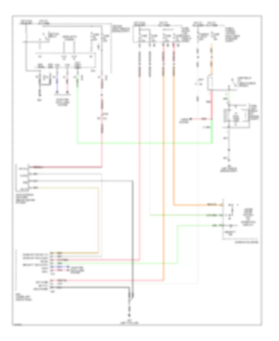
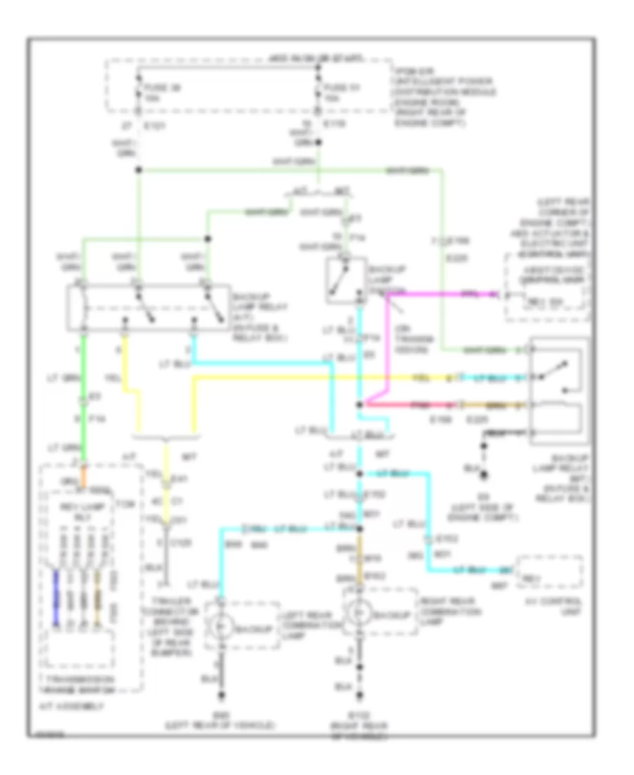
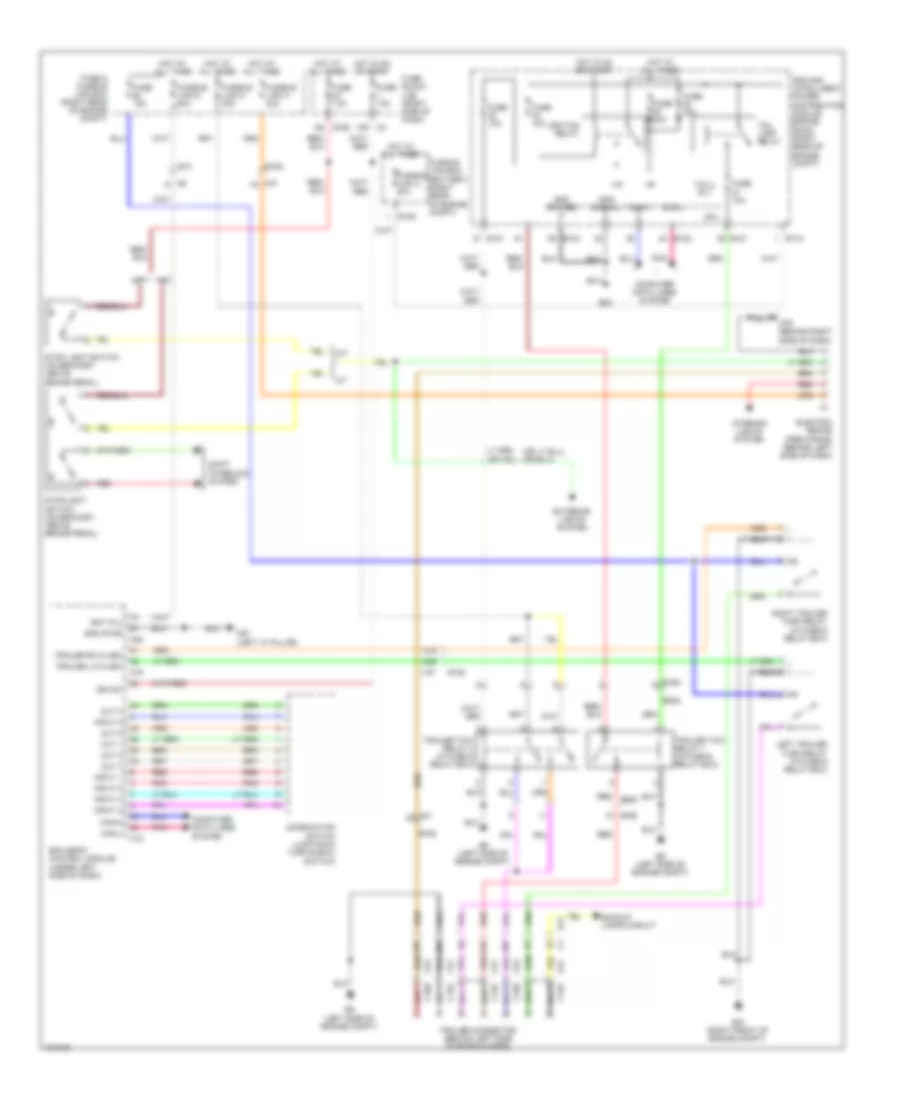
Backup Lamps Wiring Diagram for Nissan Xterra X 2013
List of elements for Backup Lamps Wiring Diagram for Nissan Xterra X 2013:
- (left rear corner of engine compt) abs actuator & electric unit (control unit)
- (on transm- ission)
- 38g
- 58j
- A/t
- A/t assembly
- Abs/tcs/vdc control unit
- Av control unit
- B132 (right rear of vehicle)
- B69 m40
- B85 (left rear of vehicle)
- Backup
- Backup lamp relay (a/t) (in fuse & relay box)
- Backup lamp relay (m/t) (in fuse & relay box)
- Backup lamp switch
- C1 4c
- C125
- E119
- E121
- E152
- E168
- E225
- E9 (left side of engine compt)
- F14
- F502
- F505
- Fuse 38 10a
- Fuse 51 10a
- Hot in on or start
- Ipdm e/r (intelligent power distribution module engine room) (right rear of engine compt)
- Left rear combination lamp
- M/t
- M16
- M31
- M97
- Pnk
- Rev
- Rev lamp rly
- Rev sw
- Right rear combination lamp
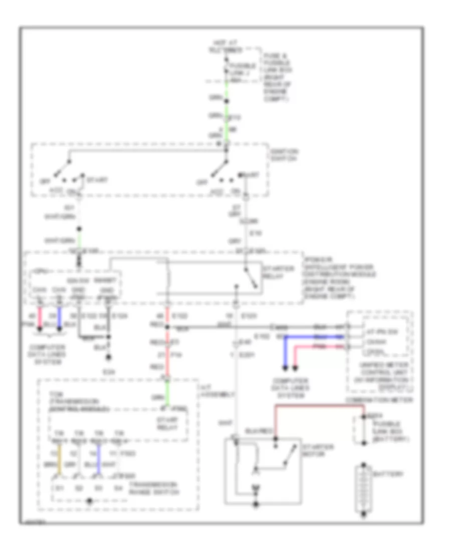
- Tcm
- Tr sw 1 f503
- Tr sw 2
- Tr sw 3
- Tr sw 4
- Trailer connector (behind left side of rear bumper)
- Transmission range switch
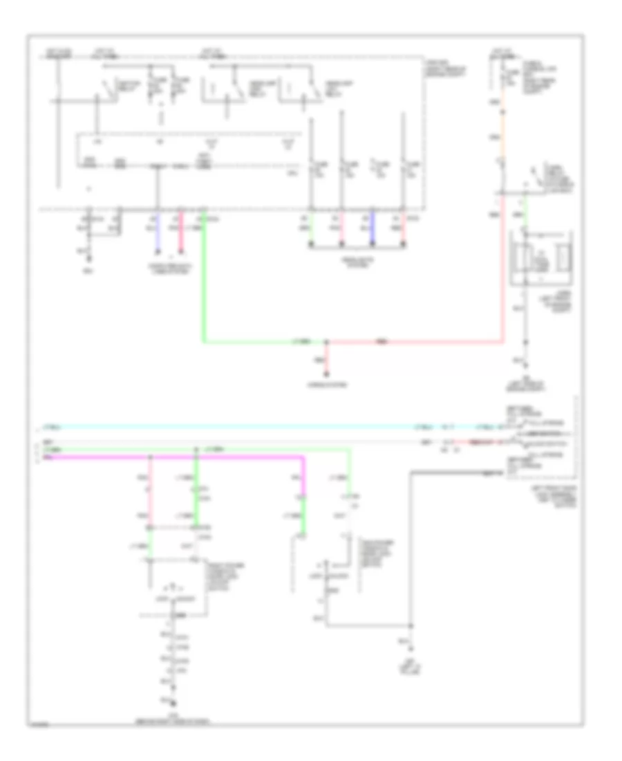
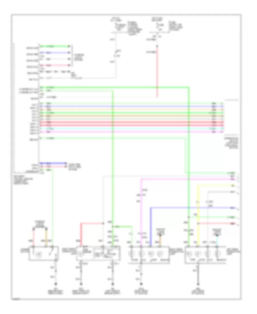
Exterior Lamps Wiring Diagram (1 of 2) for Nissan Xterra X 2013
List of elements for Exterior Lamps Wiring Diagram (1 of 2) for Nissan Xterra X 2013:
- 15p m4
- 53g
- 59j
- B132 (right rear of vehicle)
- B162
- B40
- B69
- B85 (left rear of vehicle)
- Backup
- Backup lamps circuit
- Bat (f/l)
- Bcm (body control module) (under left side of dash)
- Brk sw
- Can-h
- Can-l
- Combination switch (lighting & turn signal switch)
- Computer data lines system
- Dr sw (as)
- Dr sw (dr)
- Dr sw (rl)
- Dr sw (rr)
- E10
- E108
- E111
- E15 (right front of engine compt)
- E152
- E34
- E9 (left side of engine compt)
- Flasher out (lh)
- Flasher out (rh)
- Fuse & fusible link box (right rear of engine compt)
- Fuse 10a
- Fuse block (j/b) (right side of dash)
- Fusible link g 50a
- Gnd (pwr)
- Hazard sw
- Hazard switch
- Hot at all times
- Hot in on or start
- Ign sw
- Input 1
- Input 2
- Input 3
- Input 4
- Input 5
- Interior lights system
- Left rear combination lamp
- M16
- M18
- M19
- M20
- M31
- M31 49g
- M40
- M57 (left "a" pillar)
- M61 (behind right side of dash)
- Out 1
- Out 2
- Out 3
- Out 4
- Out 5
- Par- king
- Pnk
- Red
- Right front combination lamp
- Right rear combination lamp
- Side marker
- Stop
- Tail
- Turn
Exterior Lamps Wiring Diagram (2 of 2) for Nissan Xterra X 2013
List of elements for Exterior Lamps Wiring Diagram (2 of 2) for Nissan Xterra X 2013:
- (in fuse & relay box) (w/ hill descent control & hill start assist) stop lamp relay
- (w/ information display) unified meter control unit
- +ig
- 50g
- 8p m4
- 8q e160
- A/t
- Abs actuator & electric unit (control unit) (left rear corner of engine compt)
- Abs/tcs/vdc control unit
- B162
- B48
- Brake
- Brake (pre-wiring) (behind left side of dash)
- C1 5c
- Can-h
- Can-l
- Combination meter
- Computer data lines system
- Cpu
- D402
- D406 (left side of tailgate)
- E118
- E121
- E122
- E123
- E124
- E129
- E15 (right front of engine compt)
- E152
- E16
- E17
- E24
- E26
- E27
- E41
- E9 (left side of engine compt)
- Ecm (right rear of engine compt)
- Electric
- Fuse 10a
- Fuse 20a
- Fuse block (j/b) (right side of dash)
- Fusible link box (battery) (right rear of engine compt)
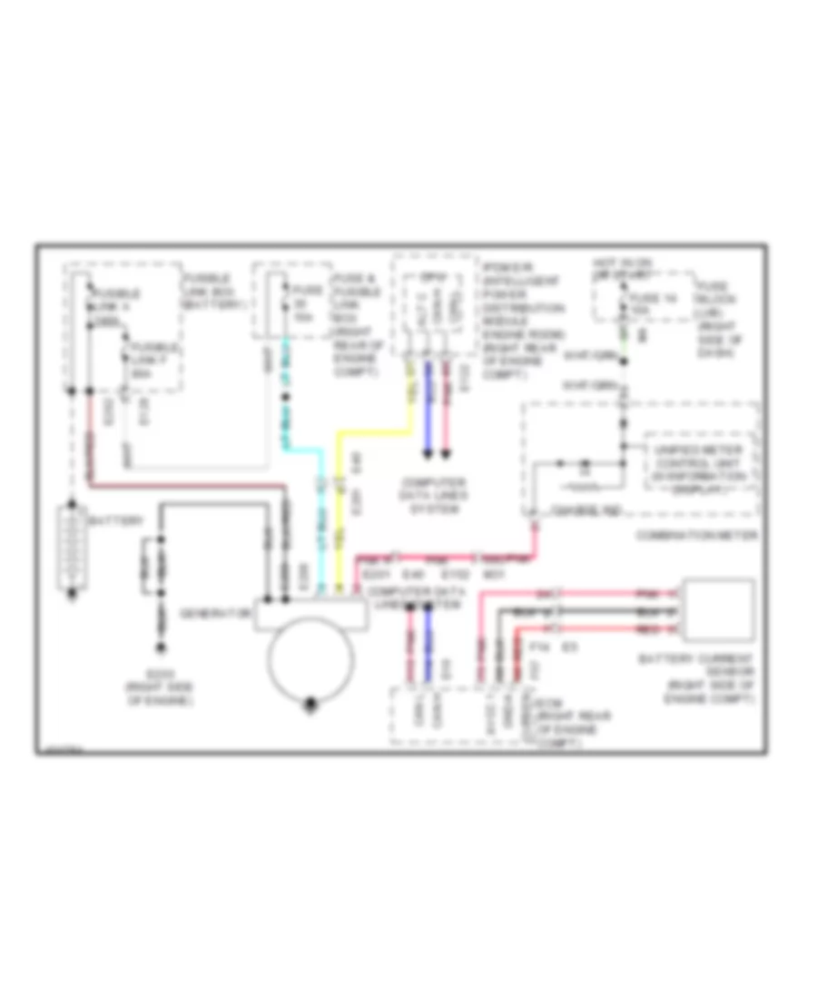
- Fusible link d 80a
- Gnd (power)
- Gnd (signal)
- High mounted stop lamp
- Hot at all times
- Hot in on or start
- Ignition relay
- Interior lights system
- Ipdm e/r (intelligent power distribution module engine room) (right rear of engine compt)
- Left front combination lamp
- Left turn ind
- License plate lamp
- M/t
- M16
- M31
- M57 (left "a" pillar)
- M91
- Par- king
- Pnk
- Red
- Right turn ind
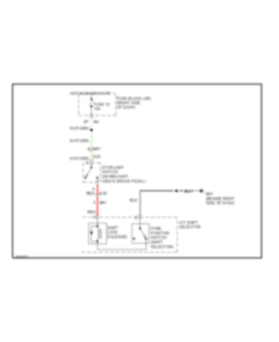
- Shift interlock system
- Side marker
- Stop lamp sw
- Stop lamp sw on
- Stop lamp switch (on bracket, above brake pedal)
- Tail lamp relay
- Tail/l rly
- Turn
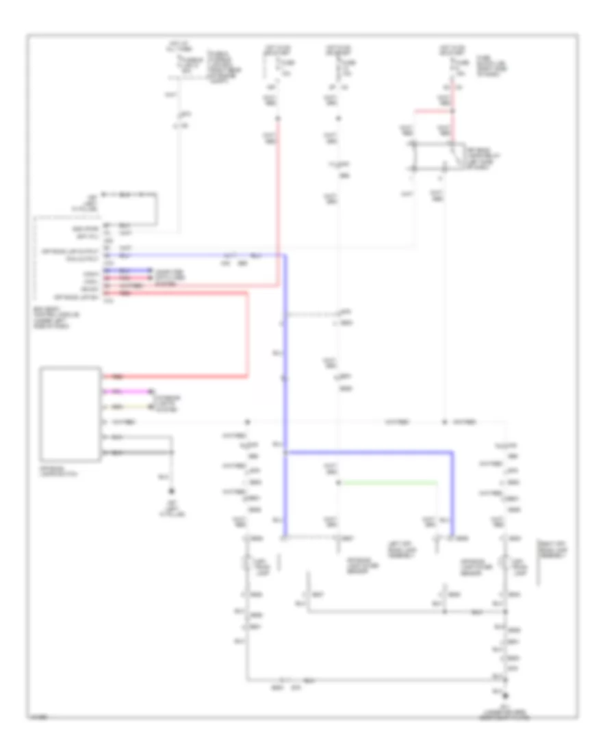
Off-Road Lighting Wiring Diagram for Nissan Xterra X 2013
List of elements for Off-Road Lighting Wiring Diagram for Nissan Xterra X 2013:
- 15p
- 2n m3
- 2p m4
- B11 (under drivers door scuff plate)
- B500
- B501
- B526
- B527
- B528
- B529
- B530
- B69
- B79
- Bat (f/l)
- Bcm (body control module) (under left side of dash)
- Can-h
- Can-l
- Computer data lines system
- E10
- Fuse & fusible link box (right rear of engine compt)
- Fuse 10a
- Fuse 15a
- Fuse block (j/b) (right side of dash)
- Fusible link g 50a
- Gnd (pwr)
- Hot at all times
- Hot in on or start
- Ign sw
- Interior lights system
- Left off- road lamp assembly
- M18
- M19
- M20
- M40
- M40 77j
- M40 78j
- M40 9j
- M57 (left "a" pillar)
- Off road lmp output
- Off road lmp sw
- Off- road lamp
- Off-road lamp cover sensor
- Off-road lamps relay (left side of dash)
- Off-road lamps switch
- Pca output
- Pnk
- Red
- Right off- road lamp assembly
Trailer Tow Wiring Diagram for Nissan Xterra X 2013
List of elements for Trailer Tow Wiring Diagram for Nissan Xterra X 2013:
- (left "a" pillar)
- +ig
- 15p m4
- 19c
- 20c
- 21c
- 22c
- 31g
- 32g
- A/t
- Backup lamps circuit
- Bat (f/l)
- Bcm (body control module) (under left side of dash)
- C125
- C150
- C51
- C52
- Can-h
- Can-l
- Combination switch (lighting & turn signal switch)
- Computer data lines system
- Cpu
- E10
- E118
- E121
- E122
- E124
- E129
- E15 (right front of engine compt)
- E152
- E160 8q
- E168
- E225
- E24
- E41
- E9 (left side of engine compt)
- Electric brake (pre-wiring) (behind left side of dash)
- Exterior lights system
- Fuse & fusible link box (right rear of engine compt)
- Fuse 10a
- Fuse 15a
- Fuse 20a
- Fuse block (j/b) (right side of dash)
- Fusible link a 80a
- Fusible link box (battery) (right rear of engine compt)
- Fusible link g 50a
- Fusible link h 30a
- Fusible link m 30a
- Gnd (power)
- Gnd (pwr)
- Gnd (signal)
- Hot at all times
- Hot in on or start
- Ign sw
- Ignition relay
- Input 1
- Input 2
- Input 3
- Input 4
- Input 5
- Interior lights system
- Ipdm e/r (intelligent power distribution module engine room) (right rear of engine compt)
- Left trailer turn relay (in fuse & relay box)
- M/t
- M18
- M19
- M20
- M31
- M31 1g
- M31 2g
- M57
- M79 (behind right side of dash)
- Out 1
- Out 2
- Out 3
- Out 4
- Out 5
- Pnk
- Red
- Red e225
- Right trailer turn relay (in fuse & relay box)
- Shift interlock system
- Stop light switch (on bracket, above brake pedal)
- Stoplight switch (on bracket, above brake pedal)
- Tail lamp relay
- Tail/l rly
- Trailer connector (behind left side of rear bumper)
- Trailer lh flash
- Trailer rh flash
- Trailer tow relay 1 (in fuse & relay box)
- Trailer tow relay 2 (in fuse & relay box)
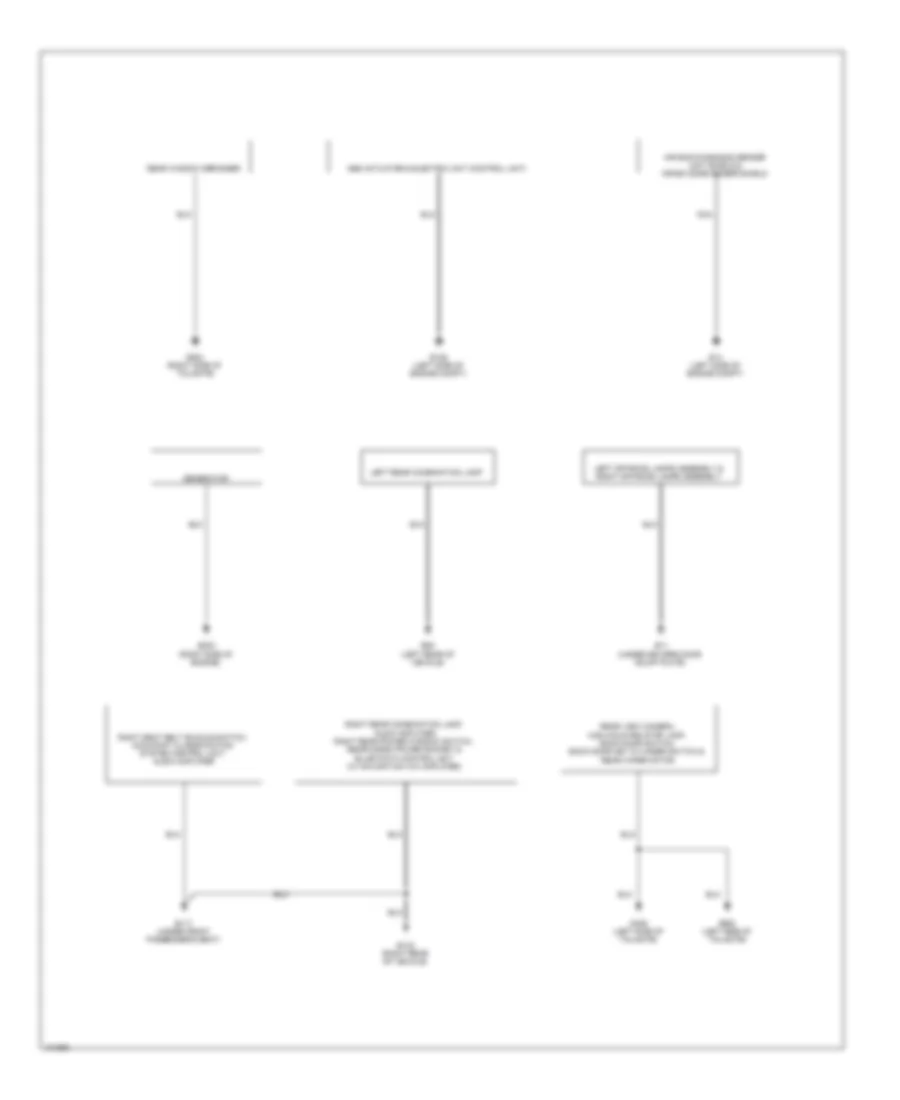
GROUND DISTRIBUTION
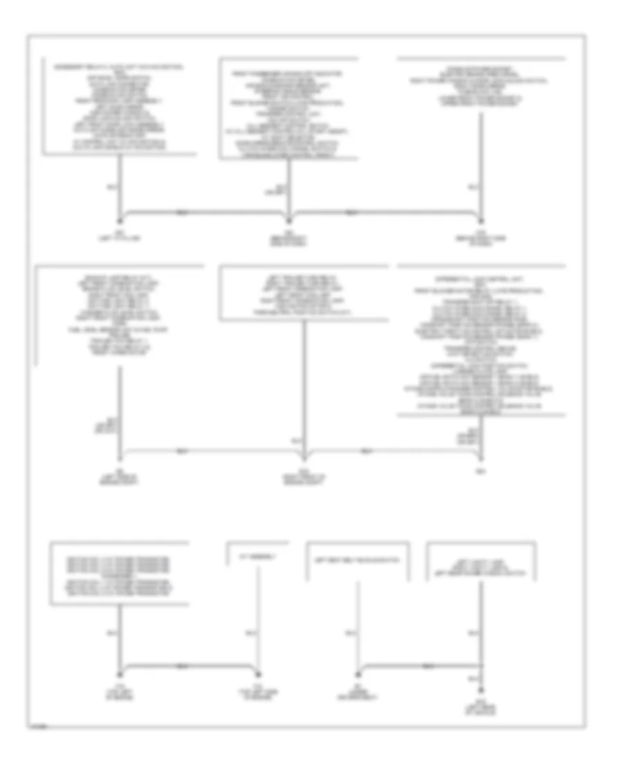
Ground Distribution Wiring Diagram (1 of 2) for Nissan Xterra X 2013
List of elements for Ground Distribution Wiring Diagram (1 of 2) for Nissan Xterra X 2013:
- A/t assembly
- Accessory relay-2, auto unit (w/o navigation), bcm, off road lamps switch, data link connector, combination meter, combination switch, front room/map lamp assembly, left door mirror, main power window & door lock/unlock switch, left front door lock assembly, auto anti-dazzling inside mirror, nats antenna amp, av control unit (w/ navigation) & aux in jack shield (w/ navigation)
- B19 (left rear of vehicle)
- B7 (under driver's seat)
- Backup lamp relay (m/t), left front combination lamp, brake fluid level switch, right front fog lamp, daytime light relay 2, daytime light relay 1, washer fluid level switch, right front combination lamp, horn, fuel level sensor unit & fuel pump, trailer, trailer tow relay 1, trailer tow relay 2 & front wiper motor
- Console power socket, electric brake (pre-wiring), right power window & door lock/unlock switch, right door mirror, fuse block (j/b), lower front power socket & upper front power socket
- Differential lock control unit, ecm, front blower motor relay (late production), ipdm e/r, transfer shut off relay 1, clutch interlock cancel relay 1, clutch interlock cancel relay 2, crankshaft position sensor (pos), camshaft position sensor (phase) (bank 2), electric throttle control actuator shield, camshaft position sensor (phase) (bank 1), atp switch, transfer control device, wait detection switch, 4lo switch, differential lock position switch, license plate lamp, air fuel ratio (a/f) sensor 1 (bank 1) shield, air fuel ratio (a/f) sensor 1 (bank 2) shield, intake manifold runner control valve motor shield, intake valve timing control solenoid valve (bank 2) shield & intake valve timing control solenoid valve (bank 2) shield
- E15 (right front of engine compt)
- E24
- E9 (left side of engine compt)
- F10 (top left side of engine)
- F16 (top left of engine)
- Front passenger air bag off indicator, combination meter, air bag diagnosis sensor unit, steering angle sensor, front air control, front blower switch (late production), hazard switch, transfer control unit, vdc off switch, hill descent control switch (w/ hill descent control/hill start assist), a/t shift selector, door mirror remote control switch, clutch interlock cancel switch & variable blower control (front)
- Ignition coil 2 (w/ power transistor), ignition coil 4 (w/ power transistor), ignition coil 6 (w/ power transistor), condenser 1, ignition coil 1 (w/ power transistor), ignition coil 3 (w/ power transistor) & ignition coil 5 (w/ power transistor)
- Left seat belt buckle switch
- Left trailer turn relay, right trailer turn relay, left front combination lamp, left front fog lamp, right front combination lamp, cooling fan motor & park/neutral position switch (m/t)
- Left vanity lamp, right vanity lamp & left rear power window switch
- M57 (left "a" pillar)
- M61 (behind right side of dash)
- M79 (behind right side of dash)
Ground Distribution Wiring Diagram (2 of 2) for Nissan Xterra X 2013
List of elements for Ground Distribution Wiring Diagram (2 of 2) for Nissan Xterra X 2013:
- Abs actuator & electric unit (control unit)
- Air bag diagnosis sensor unit shield & crash zone sensor shield
- B11 (under drivers door scuff plate)
- B117 (under front passenger's seat)
- B132 (right rear of vehicle)
- B85 (left rear of vehicle)
- D406 (left side of tailgate)
- D603 (right side of tailgate)
- D652 (left side of tailgate)
- E126 (left side of engine compt)
- E14 (left side of engine compt)
- E203 (right side of engine)
- Generator
- Left off-road lamps assembly & right off-road lamps assembly
- Left rear combination lamp
- Nca
- Rear view camera, high mounted stop lamp, back door switch, back door key cylinder switch & rear wiper motor
- Rear window defogger
- Right seat belt buckle switch, occupant classification system control unit, audio amplifier
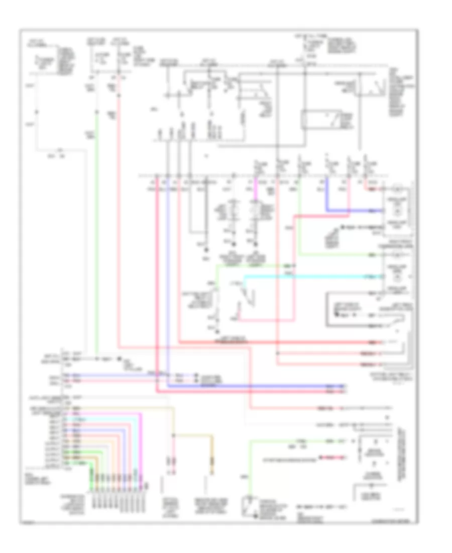
HEADLIGHTS
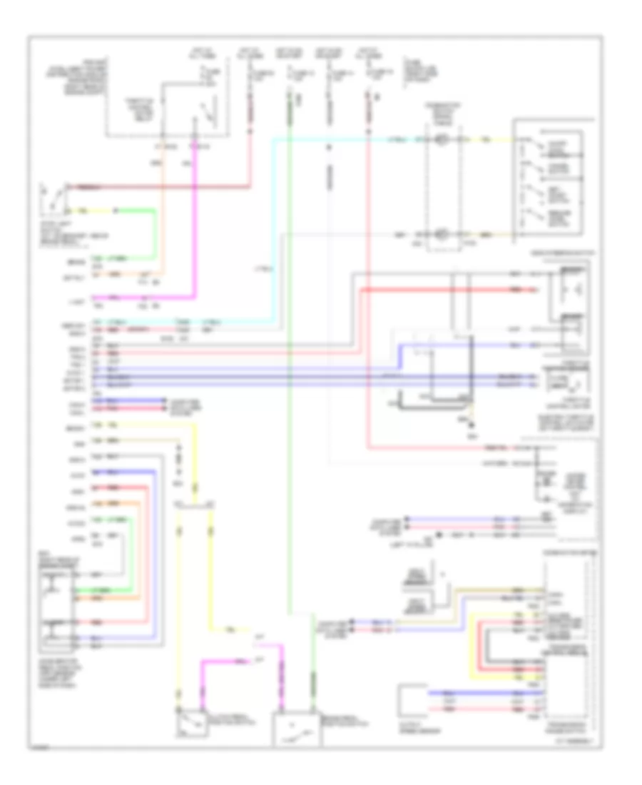
Headlights Wiring Diagram, with DRL for Nissan Xterra X 2013
List of elements for Headlights Wiring Diagram, with DRL for Nissan Xterra X 2013:
- (left side of engine compt)
- (left side of engine compt) e9
- 68j
- Auto light sens input 2 m20
- B69
- Bat (f/l)
- Bcm (under left side of dash)
- Brake indicator
- Can-h
- Can-l
- Charge indicator
- Combination meter
- Combination switch (lighting & turn signal switch)
- Computer data lines system
- Cpu
- Daytime light relay 1 (in fuse & relay box)
- Daytime light relay 2 (in fuse & relay box)
- Dtrl rly cont
- E10
- E107
- E118
- E119
- E122
- E123
- E124
- E129
- E15 (right front of engine compt)
- E24
- E9 (left side of engine compt)
- Fr fog
- Front fog lamp relay
- Fuse & fusible link box (right rear of engine compt)
- Fuse 10a
- Fuse 15a
- Fuse 20a
- Fuse block (j/b) (right side of dash)
- Fusible link box (battery) (right rear of engine compt)
- Fusible link d 80a
- Fusible link g 50a
- Gnd (pwr)
- Gnd (sig)
- H/lp hi
- H/lp lo
- Head- lamp high relay
- Headlamp high
- Headlamp low
- Headlamp low relay
- High beam indicator
- Hot at all times
- Hot in on or start
- Ig+
- Ignition relay
- Input
- Input 1
- Input 2
- Input 3
- Input 4
- Input 5
- Ipdm e/r (intelligent power distribution module engine room) (right rear of engine compt)
- Keyless & auto light sens gnd
- Left front combination lamp
- Left front fog lamp
- M18
- M20
- M28
- M40
- M57 (left "a" pillar)
- M61 (behind right side of dash)
- Optical sensor (w/ auto light system)
- Output
- Output 1
- Output 2
- Output 3
- Output 4
- Output 5
- Parking brake switch (on base of parking brake lever)
- Pnk
- Red
- Remote keyless entry receiver (behind right side of of dash)
- Right front combination lamp
- Right front fog lamp
- Starting/charging system
- Unified meter control unit (w/ information display)
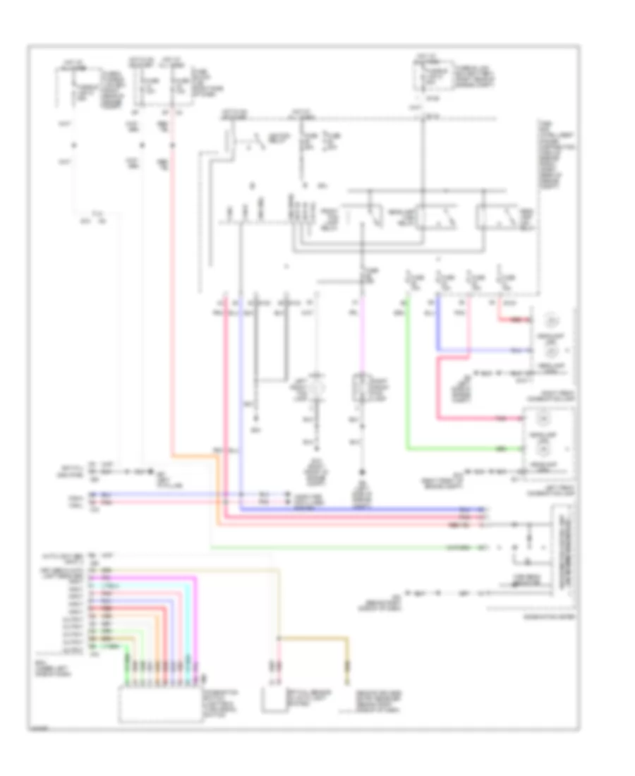
Headlights Wiring Diagram, without DRL for Nissan Xterra X 2013
List of elements for Headlights Wiring Diagram, without DRL for Nissan Xterra X 2013:
- Auto light sen input 2
- Bat (f/l)
- Bcm (under left side of dash)
- Can-h
- Can-l
- Combination meter
- Combination switch (lighting & turn signal switch)
- Computer data lines system
- Cpu
- E10
- E107
- E11
- E118
- E122
- E123
- E124
- E129
- E15 (right front of engine compt)
- E24
- E9 (left side of engine compt)
- Fr fog
- Front fog lamp relay
- Fuse & fusible link box (right rear of engine compt)
- Fuse 10a
- Fuse 15a
- Fuse 20a
- Fuse block (j/b) (right side of dash)
- Fusible link box (battery) (right rear of engine compt)
- Fusible link d 80a
- Fusible link g 50a
- Gnd (pwr)
- Gnd (sig)
- H/lp hi
- H/lp lo
- Head- lamp low relay
- Headlamp high
- Headlamp high relay
- Headlamp low
- High beam indicator
- Hot at all times
- Hot in on or start
- Ig+
- Ignition relay
- Input
- Ipdm e/r (intelligent power distribution module engine room) (right rear of engine compt)
- Keyless & auto light sens gnd input
- Left front combination lamp
- Left front fog lamp
- M18
- M20
- M28
- M57 (left "a" pillar)
- M61 (behind right side of of dash)
- Optical sensor (w/ auto light system)
- Output
- Pnk
- Red
- Remote keyless entry receiver (behind right side of of dash)
- Right front combination lamp
- Right front fog lamp
- Unified meter control unit (w/ information display)
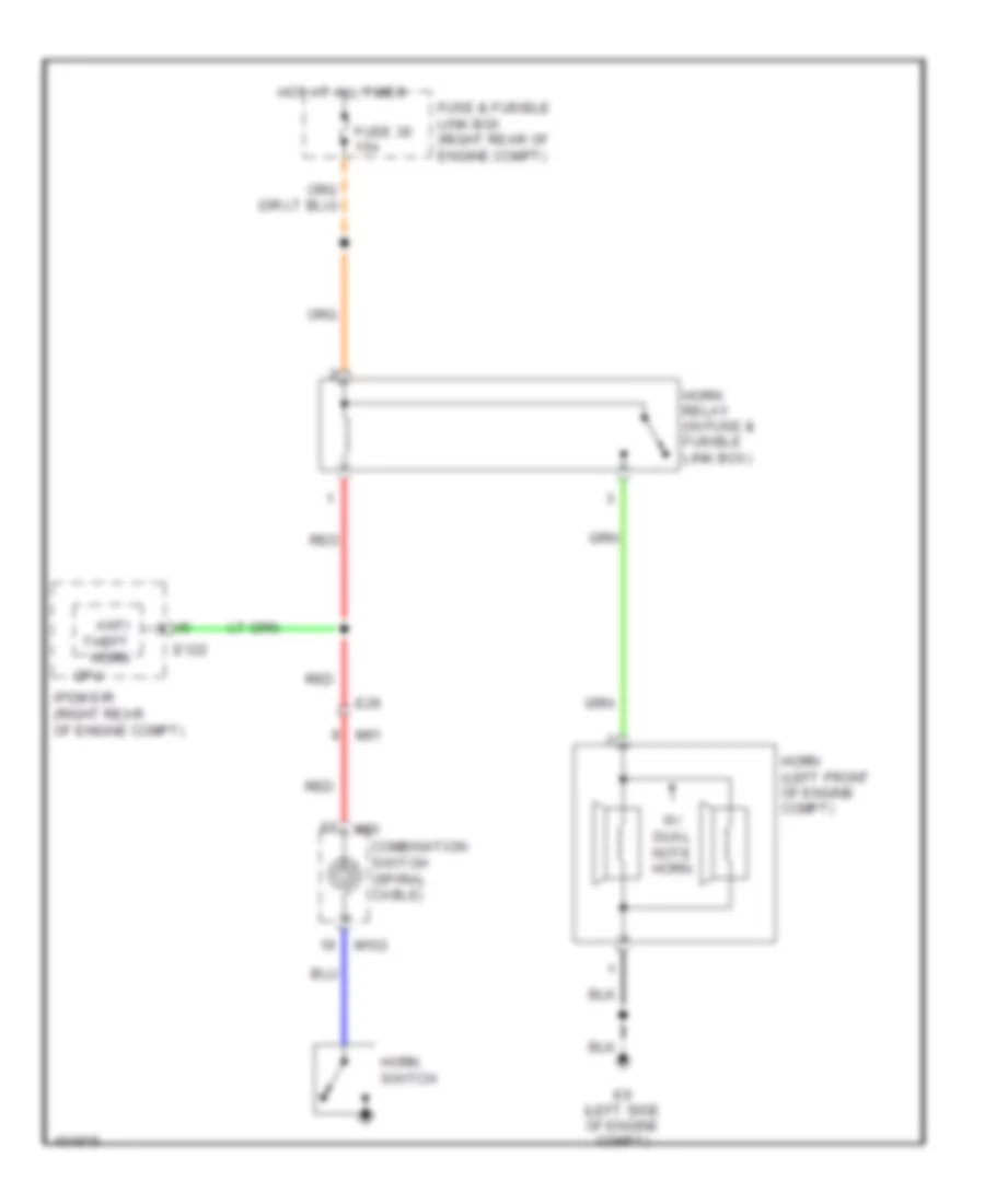
HORN
Horn Wiring Diagram for Nissan Xterra X 2013
List of elements for Horn Wiring Diagram for Nissan Xterra X 2013:
- Anti theft horn
- Combination switch (spiral cable)
- Cpu
- E122
- E26
- E9 (left side of engine compt)
- Fuse & fusible link box (right rear of engine compt)
- Fuse 30 15a
- Horn (left front of engine compt)
- Horn relay (in fuse & fusible link box)
- Horn switch
- Hot at all times
- Ipdm e/r (right rear of engine compt)
- M102
- M30
- M91
- Red
- W/ dual note horn
INSTRUMENT CLUSTER
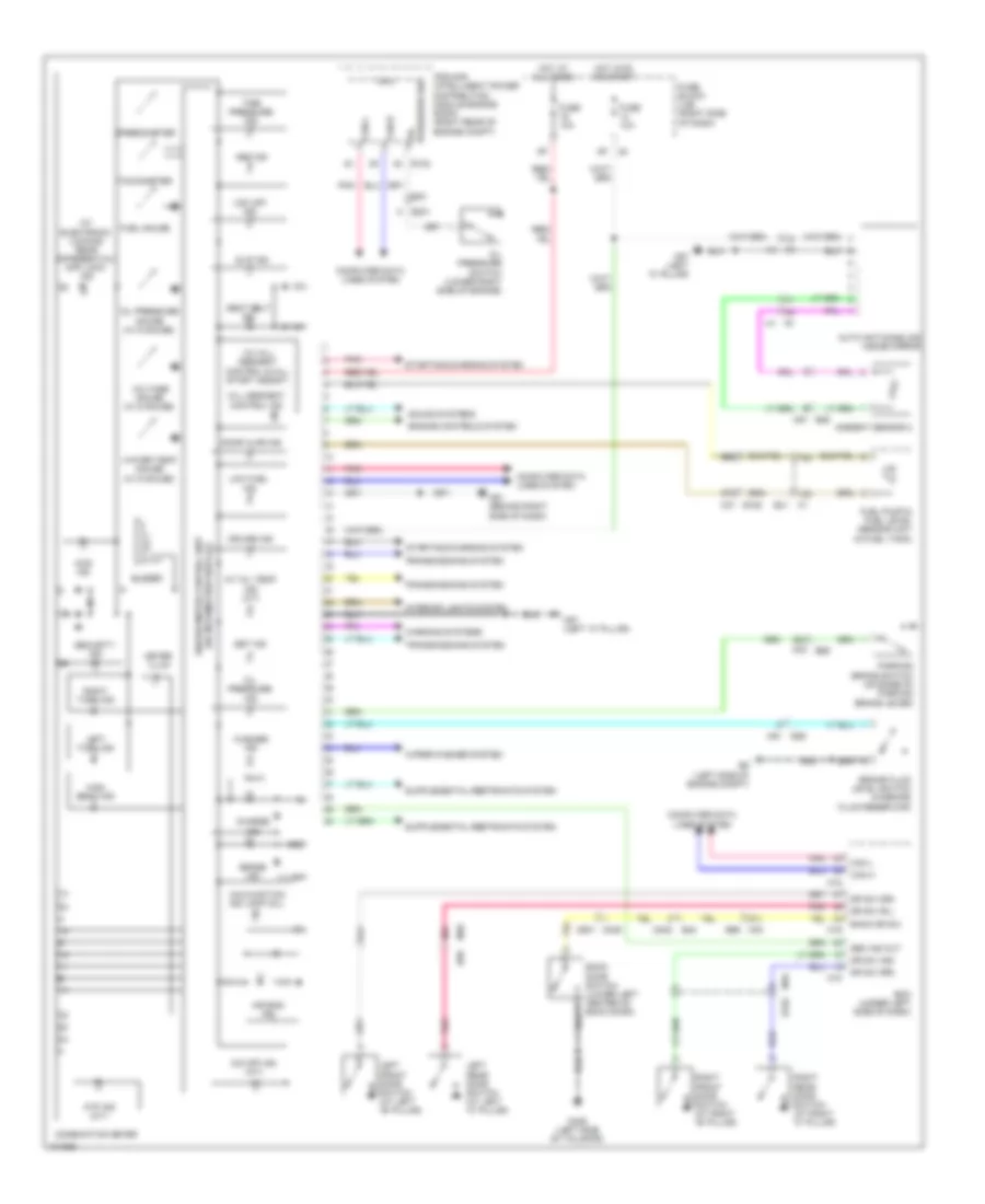
Instrument Cluster Wiring Diagram for Nissan Xterra X 2013
List of elements for Instrument Cluster Wiring Diagram for Nissan Xterra X 2013:
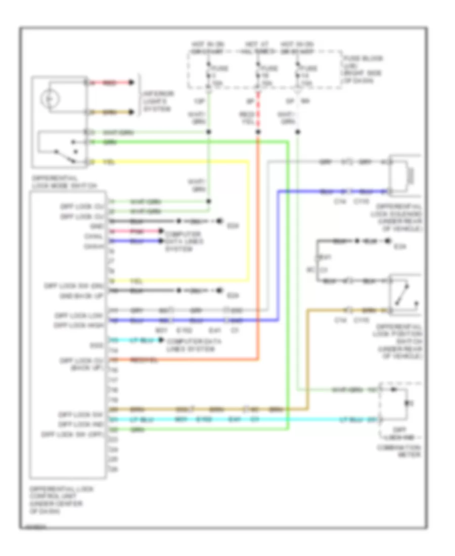
- (w/ electronic locking rear differential) diff lock ind
- (w/ hill descent control & hill start assist)
- (w/ information display)
- 13c
- 14c
- 4wd ind
- 57j
- 60j
- 61j
- 66g
- 67g
- 68j
- A/t oil temp ind (a/t)
- Abs ind
- Air bag ind
- Ambient sensor 2
- Atp ind (a/t)
- Auto anti-dazzling inside mirror
- B162
- B48
- B69
- Back door switch (lower left center of back door)
- Back dr sw
- Bcm (under left side of dash)
- Brake fluid level switch (in brake fluid reservoir)
- Brake ind
- Buzzer
- Can h
- Can l
- Can-h
- Can-l
- Charge ind
- Combination meter
- Computer data lines system
- Cpu
- Cruise ind
- D402
- D406 (left side of tailgate)
- D501 d405
- Door ajar ind
- Dr sw (as)
- Dr sw (dr)
- Dr sw (rl)
- Dr sw (rr)
- E122
- E201
- E26
- E40
- E41 c1
- E9 (left side of engine compt)
- Engine controls system
- Fuel gauge
- Fuel pump & fuel level sensor unit (in fuel tank)
- Fuse 10a
- Fuse block (j/b) (right side of dash)
- High beam ind
- Hill descent control ind
- Hot at all times
- Hot in on or start
- Interior lights system
- Ipdm e/r (intelligent power distribution module engine room) (right rear of engine compt)
- Left front door switch (at left "b" pillar)
- Left rear door switch (at left "c" pillar)
- Left turn ind
- Low fuel ind
- M16
- M18
- M19
- M31 e152
- M40
- M40 b69
- M57 (left "a" pillar)
- M61 (behind right side of dash)
- M91
- M91 e26
- Malfunction ind lamp (mil)
- Meter illum
- O/d off ind (a/t)
- Oil pressure gauge (w/ 6 gauge)
- Oil pressure ind
- Oil pressure switch (lower right side of engine)
- Parking brake switch (on base of parking brake lever)
- Pnk
- Pressure sw oil
- R1 m1
- Right front door switch (at right "b" pillar)
- Right rear door switch (at right "c" pillar)
- Right turn ind
- Seat belt ind
- Sec ind out
- Security ind
- Set ind
- Slip ind
- Sound systems
- Speedometer
- Starting/charging system
- Tachometer
- Tire pressure ind
- Transmissions system
- Unified meter control unit
- Vdc off ind
- Voltage gauge (w/ 6 gauge)
- Warning systems
- Washer ind
- Water temp gauge (w/ 6 gauge)
- Wiper/washer system
INTERIOR LIGHTS
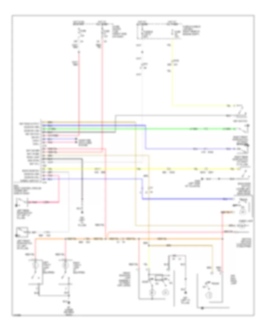
Courtesy Lamps Wiring Diagram for Nissan Xterra X 2013
List of elements for Courtesy Lamps Wiring Diagram for Nissan Xterra X 2013:
- 15p
- 2nd row room lamp
- 55g m31
- 57j
- 60j
- 61j
- 69j
- B162
- B48
- B69
- B7 (under driver's seat)
- Back door sw
- Back door switch (lower left center of back door)
- Bat (f/l)
- Bat (fuse)
- Bat saver
- Bcm (body control module) (under left side of dash)
- Can-h
- Can-l
- Cargo lamp
- Cargo lamp out
- Computer data lines system
- D402
- D405
- D406 (left side of tailgate)
- D501
- Door
- Door sw (as)
- Door sw (dr)
- Door sw (rl)
- Door sw (rr)
- E10
- E152
- Front room/map lamp assembly (w/ front map lamps)
- Fuse & fusible link box (right rear of engine compt)
- Fuse 10a
- Fuse block (j/b) (right side of dash)
- Fusible link g 50a
- Gnd (pwr)
- Hot at all times
- Hot in on or start
- Ign sw
- Ignition keyhole illumination (if equipped)
- Key ring output
- Key switch
- Left front door switch (at left "b" pillar)
- Left rear door switch (at left "c" pillar)
- Left vanity lamp (if equipped)
- M16
- M18
- M19
- M20
- M40
- M57 (left "a" pillar)
- Off
- Pnk
- Right front door switch (at right "b" pillar)
- Right rear door switch (at right "c" pillar)
- Right vanity lamp (if equipped)
- Room lamp
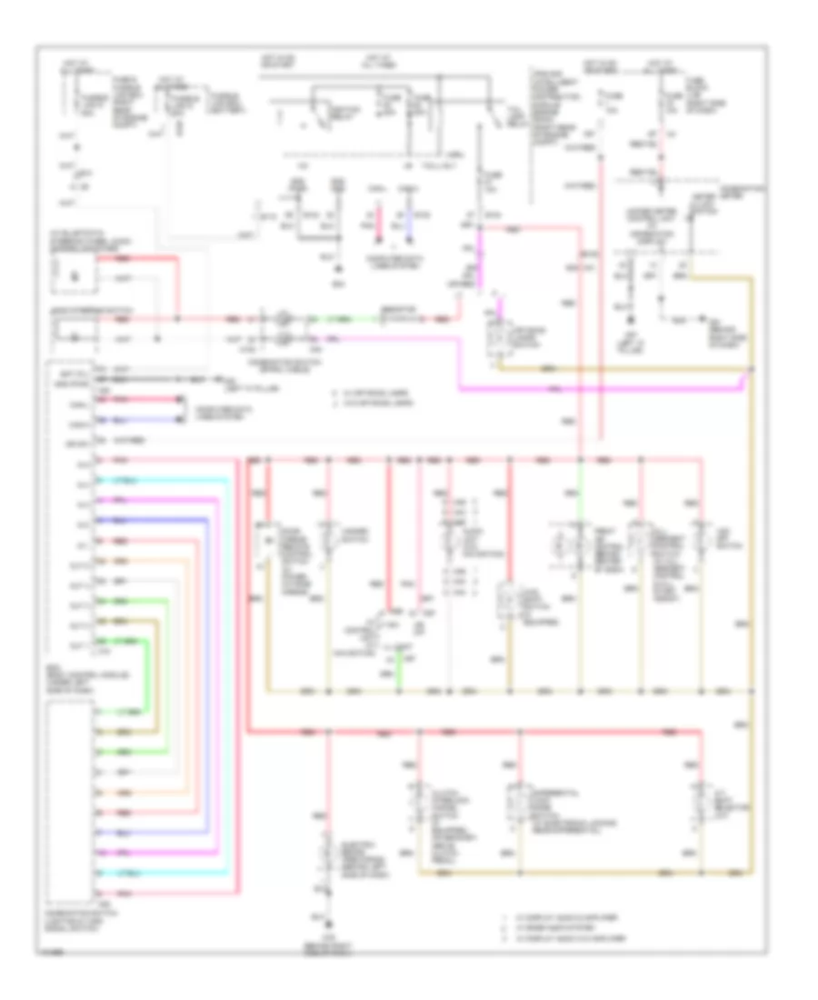
Instrument Illumination Wiring Diagram for Nissan Xterra X 2013
List of elements for Instrument Illumination Wiring Diagram for Nissan Xterra X 2013:
- +ig
- 15p
- 49g
- 4wd shift switch (if equipped)
- 62g m31
- A/t shift selector (a/t)
- Ascd steering switch
- Audio unit (w/o navigation)
- Av control unit (w/ navigation)
- Bat (f/l)
- Bcm (body control module) (under left side of dash)
- Can-h
- Can-l
- Clutch interlock cancel switch (if equipped) (on bracket, above clutch pedal)
- Combination meter
- Combination switch (lighting & turn signal switch)
- Combination switch (spiral cable)
- Computer data lines system
- Cpu
- Differential lock mode switch (w/ electronic locking rear differential)
- Door mirror remote control switch (w/ power outside mirror)
- E10
- E118
- E122
- E124
- E129
- E152
- E24
- Electric brake (pre-wiring) (behind left side of dash)
- Front air control (behind center of dash)
- Fuse & fusible link box (right rear of engine compt)
- Fuse 10a
- Fuse 20a
- Fuse block (j/b) (right side of dash)
- Fusible link box (battery)
- Fusible link d 80a
- Fusible link g 50a
- Gnd (pwr)
- Gnd (sig)
- Hazard switch
- Hill descent control switch (w/ hill descent control & hill start assist)
- Hot at all times
- Hot in on or start
- Ign sw
- Ignition relay
- Ill cont
- In 1
- In 2
- In 3
- In 4
- In 5
- Ipdm e/r (intelligent power distribution module engine room) (right rear of engine compt)
- Lt sw
- M102
- M18
- M20
- M28
- M30
- M43
- M44
- M46
- M49
- M57 (left "a" pillar)
- M61 (behind right side of dash)
- M79 (behind right side of dash)
- M96
- M97
- Meter illumi- nation
- Mr o/p
- Off road lamps switch
- Out 1
- Out 2
- Out 3
- Out 4
- Out 5
- Pnk
- Red
- Resistor
- Tail lamp relay
- Tail/l rly
- Unified meter control unit (w/ information display)
- Vdc off switch
- W/ base audio system
- W/ display audio & amplifier
- W/ display audio w/o amplifier
- W/ off road lamps
- W/o off road lamps
NAVIGATION
Navigation Wiring Diagram (1 of 2) for Nissan Xterra X 2013
List of elements for Navigation Wiring Diagram (1 of 2) for Nissan Xterra X 2013:
- 16p
- 51m
- 52m
- 54m
- 55m
- 57m
- 58m
- 60m
- 61m
- 63m
- 72m
- 73m
- 74m
- 76m
- 77m
- 78m
- 79m
- Acc
- Amp 0n/off sig
- Amp on
- Audio amplifier (under front passenger's seat)
- Aux l (+)
- Av control unit
- B106
- B117 (under front passenger's seat)
- B132 (right rear of vehicle)
- B149
- B158 gnd
- B159 frsp rh out (+)
- B159 frsp rh out (-)
- B69
- Bat
- Can-h
- Can-l
- Combination meter
- Computer data lines system
- D101
- D152
- D153
- D201
- D301
- Exterior lights system
- Fr lh tw (+)
- Fr lh tw (-)
- Fr rh tw (+)
- Fr rh tw (-)
- Fr sp lh (+)
- Fr sp lh (-)
- Fr sp rh (+)
- Fr sp rh(-)
- Frsp lh (+) in
- Frsp lh (-) in
- Frsp lh out (+)
- Frsp lh out (-)
- Frsp rh (+) in
- Frsp rh (-) in
- Fuse & fusible link box (right rear of engine compt)
- Fuse 10a
- Fuse 15a
- Fuse 29 20a
- Fuse block (j/b) (right side of dash)
- Gnd
- Hot at all times
- Hot in on or acc
- Interior lights system
- Left front door speaker
- Left front tweeter
- Left rear door speaker
- Left rear tweeter
- Light sw
- M36
- M40
- M75
- M96
- M97
- Mr output
- Pnk
- Red
- Reverse
- Right front door speaker
- Right front tweeter
- Right rear door speaker
- Right rear tweeter
- Rr sp lh (+)
- Rr sp lh (-)
- Rr sp rh (+)
- Rr sp rh (-)
- Rrsp lh (+) in
- Rrsp lh (-) in
- Rrsp lh out (+)
- Rrsp lh out (-)
- Rrsp rh (+) in
- Rrsp rh (-) in
- Rrsp rh out (+)
- Rrsp rh out (-)
- Spd
- Strg sw a
- Strg sw b
- Strg sw gnd
- Subwoofer (under driver's seat)
- Unified meter control unit (w/ information display)
- Woofer (+) 1
- Woofer (+) 2
- Woofer (-) 1
- Woofer (-) 2
Navigation Wiring Diagram (2 of 2) for Nissan Xterra X 2013
List of elements for Navigation Wiring Diagram (2 of 2) for Nissan Xterra X 2013:
- (near front center of headliner) microphone
- 56j
- 65j
- 66j
- 67j
- Ant main
- Aux gnd
- Aux in jack
- Aux r (+)
- Av control unit
- B69
- Cam gnd
- Cam video
- Camera on
- Combination switch (spiral cable)
- D402 b48
- D404
- D406 (left side of tail- gate)
- D503
- Fuse 10a
- Fuse block (j/b) (right side of dash)
- Gps ant
- Gps antenna
- Gps shield
- Hot in on or start
- Ign
- Ill cont
- Interior lights system
- M100
- M102
- M169
- M204
- M205
- M30
- M38
- M40
- M500
- M57 (left "a" pillar)
- M63
- M67
- M97
- M98
- M99
- Mic gnd
- Mic sig
- Mic vcc
- Mode/ end
- Phone/ send
- Pnk
- R1 m1
- Rear view camera (rear tailgate assembly)
- Red
- Rod antenna
- Sat ant
- Sat shield
- Satellite antenna
- Seek down
- Seek up
- Shield
- Source
- Steering wheel audio control switches
- Usb d+
- Usb d-
- Usb gnd
- Usb interface
- Vbus
- Video gnd
- Vol down
- Vol up
POWER DISTRIBUTION
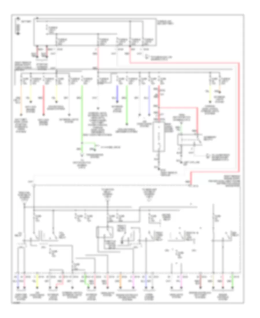
Power Distribution Wiring Diagram (1 of 2) for Nissan Xterra X 2013
List of elements for Power Distribution Wiring Diagram (1 of 2) for Nissan Xterra X 2013:
- (left a-pillar) m57
- (right rear of engine compt) fuse & fusible link box
- (right rear of engine compt) ipdm e/r (intelligent power distribution module engine room)
- 5g red
- A/c relay
- Accessory relay-2
- Air conditioning system
- Anti-lock brakes system
- Anti-theft, door locks, starting/ charging & horns systems
- B132 (right rear of vehicle)
- B163 red
- Battery
- Computer data lines system
- Cooling fans & defogger systems
- Cpu
- E118
- E119
- E121
- E122
- E123
- E124
- E128
- E129
- E152
- E202
- E204
- E30
- Ecm relay
- Engine controls & anti-theft systems
- Engine controls & cruise control systems
- Engine controls system
- Exterior lights system
- From fuel pump relay (diagram 2 of 2)
- From ignition switch (diagram 2 of 2)
- Front fog lamp relay
- Front wiper high relay
- Front wiper relay
- Fuse 10a
- Fuse 15a
- Fuse 20a
- Fuse 30a
- Fusible link a 140a
- Fusible link b 60a
- Fusible link box (battery)
- Fusible link c 80a
- Fusible link d 80a
- Fusible link e 100a
- Fusible link f 80a
- Fusible link g 50a
- Fusible link h 30a
- Fusible link i 40a
- Fusible link j 40a
- Fusible link l 30a
- Fusible link m 30a
- Fusible link n 40a
- Headlights system
- Heated mirror relay
- Interior lights & exterior lights systems
- Interior lights, exterior lights, headlights, wiper/washer, anti-theft, power windows, warning, door locks, defogger & body computer systems
- M17
- M31
- Navigation & sound systems
- Pnk
- Rear cargo power socket
- Red
- Starting/ charging system
- Tail lamp relay
- Throttle control motor relay
- To fuse block (j/b) (diagram 2 of 2)
- To headlamp low relay (diagram 2 of 2)
- To ignition relay (diagram 2 of 2)
- To ignition switch (diagram 2 of 2)
- To lower front power socket (diagram 2 of 2)
- Transmissions system
- W/ 4-wheel drive
- Warning, door locks & interior lights systems
- Wiper/ washer system
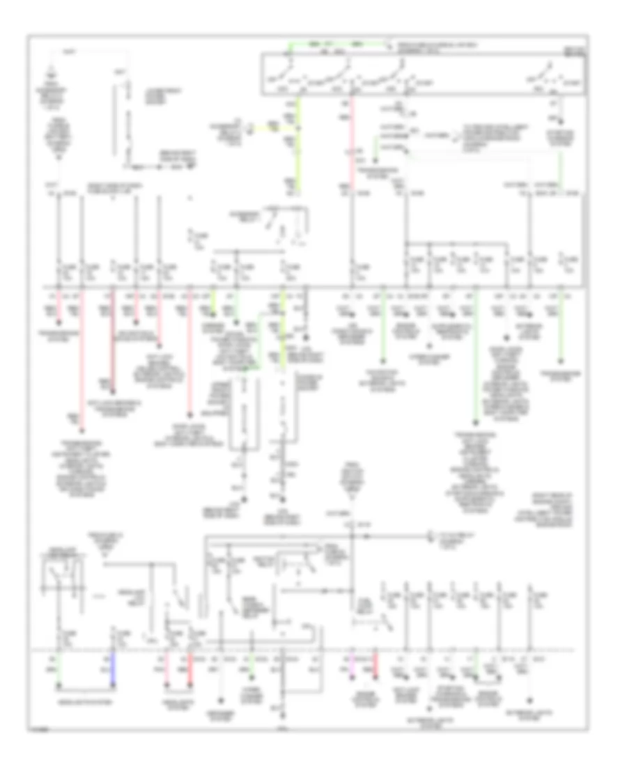
Power Distribution Wiring Diagram (2 of 2) for Nissan Xterra X 2013
List of elements for Power Distribution Wiring Diagram (2 of 2) for Nissan Xterra X 2013:
- (behind right side of dash) m79
- (right rear of engine compt) ipdm e/r (intelligent power distribution module engine room)
- (right side of dash) fuse block (j/b)
- 10p
- 12p
- 13p
- 15p
- 16p
- 1q e160
- 4n m3
- Acc
- Accessory relay 1
- Air conditioning & defogger systems
- Anti-lock brakes & transmissions systems
- Anti-lock brakes system
- Anti-lock brakes, cruise control, exterior lights & engine controls systems
- Console power socket
- Cpu
- Defogger system
- Door locks, anti-theft, interior lights & body computer systems
- Door locks, anti-theft, warning, engine controls, defogger, interior lights, power windows, headlights, exterior lights, wiper/washer & body computer systems
- E10
- E119
- E121
- E122
- E123
- E124
- E158
- E159
- E160
- E24
- Engine controls system
- Exterior lights system
- From accessory relay-2 (diagram 1 of 2)
- From fuse & fusible link box (diagram 1 of 2)
- From fuse 43 (diagram 1 of 2)
- From fuse 52 (diagram 1 of 2)
- From fusible link box (battery) (diagram 1 of 2)
- From ignition switch (diagram 2 of 2)
- Fuel pump relay
- Fuse 10a
- Fuse 15a
- Fuse 20a
- Headlamp high relay
- Headlamp low relay
- Headlights system
- Ig2
- Ignition relay
- Ignition switch
- Lower front power socket
- M204
- M63
- M79 (behind right side of dash)
- Mirrors system
- Navigation & sound systems
- Navigation, sound & exterior lights systems
- Off
- Pnk
- Rear window defogger relay
- Red
- Sound, power windows, door locks, anti-theft, navigation & body computer systems
- Start
- Starting/ charging & transmissions systems
- Starting/ charging system
- To a/c relay (diagram 1 of 2)
- To accessory relay-2 (diagram 1 of 2)
- To ipdm e/r (intelligent power distribution module engine room) (diagram 2 of 2)
- Transmissions system
- Transmissions, anti-theft, instrument cluster, headlights, interior lights, warning, engine controls, exterior lights & air conditioning systems
- Upper front power socket (if equipped)
- Wiper/ washer system
- Wiper/washer system
POWER DOOR LOCKS
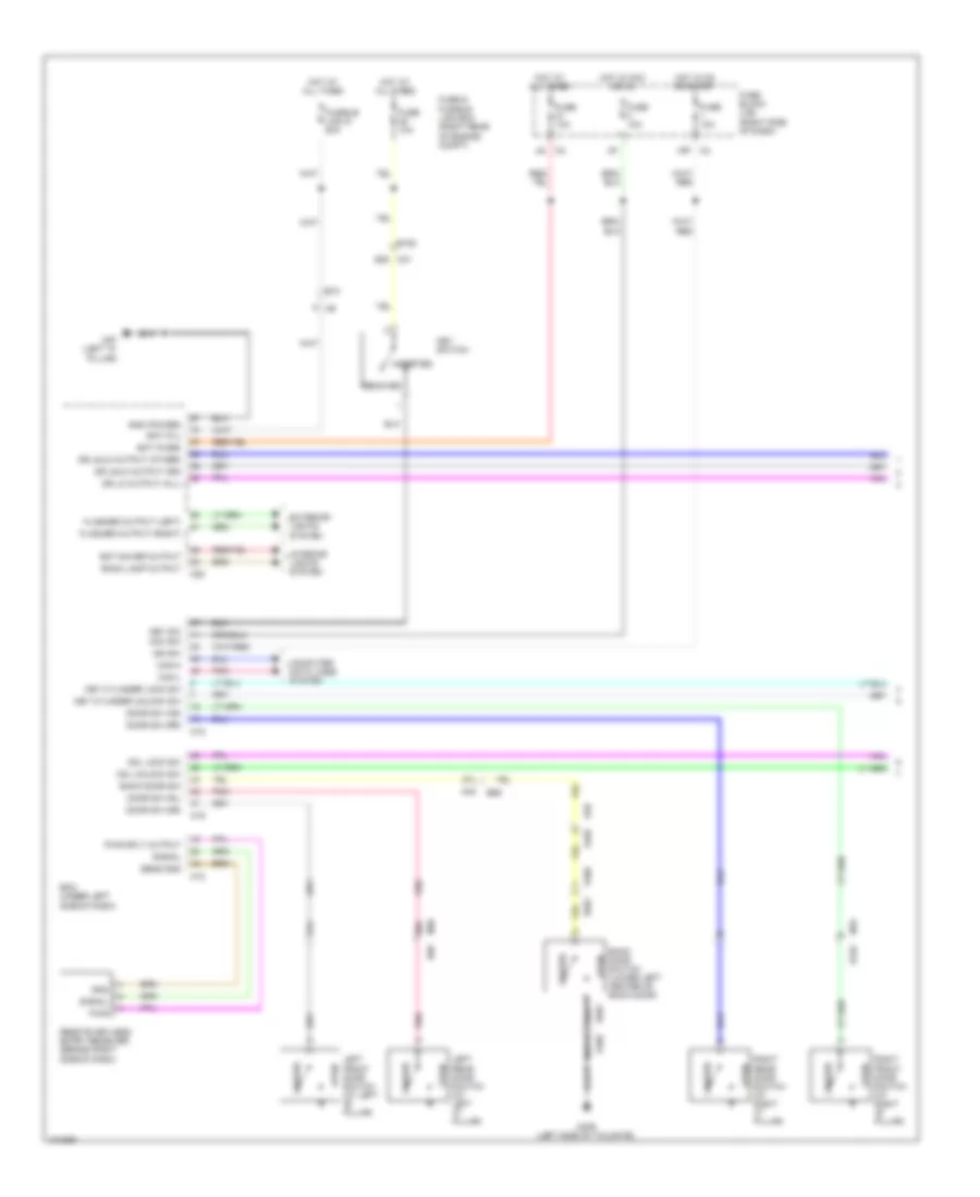
Door Lock & Keyless Entry Wiring Diagram (1 of 2) for Nissan Xterra X 2013
List of elements for Door Lock & Keyless Entry Wiring Diagram (1 of 2) for Nissan Xterra X 2013:
- 15p m4
- 4n m3
- 55g m31
- 57j
- 60j
- 61j
- Acc sw
- B162
- B48
- B69
- Back door sw
- Back door switch (lower left center of back door)
- Bat (f/l)
- Bat (fuse)
- Bat saver output
- Bcm (under left side of dash)
- Can-h
- Can-l
- Cdl lock sw
- Cdl unlock sw
- Closed
- Computer data lines system
- D402
- D405
- D406 (left side of tailgate)
- D501
- Door sw (as)
- Door sw (dr)
- Door sw (rl)
- Door sw (rr)
- Dr lk output (all)
- Dr unlk output (dr)
- Dr unlk output (other)
- E10
- E152
- Exterior lights system
- Flasher output (left)
- Flasher output (right)
- Fuse & fusible link box (right rear of engine compt)
- Fuse 10a
- Fuse block (j/b) (right side of dash)
- Fusible link g 50a
- Gnd
- Gnd (power)
- Hot at all times
- Hot in acc or on
- Hot in on or start
- Ign sw
- Inserted
- Interior lights system
- Key cylinder lock sw
- Key cylinder unlock sw
- Key sw
- Key switch
- Left front door switch (at left "b" pillar)
- Left rear door switch (at left "c" pillar)
- M16
- M18
- M19
- M20
- M40
- M57 (left "a" pillar)
- Open
- Pnk
- Pwr
- Pwr sply output
- Remote keyless entry receiver (behind right side of dash)
- Removed
- Right front door switch (at right "b" pillar)
- Right rear door switch (at right "c" pillar)
- Room lamp output
- Sens gnd
- Signal
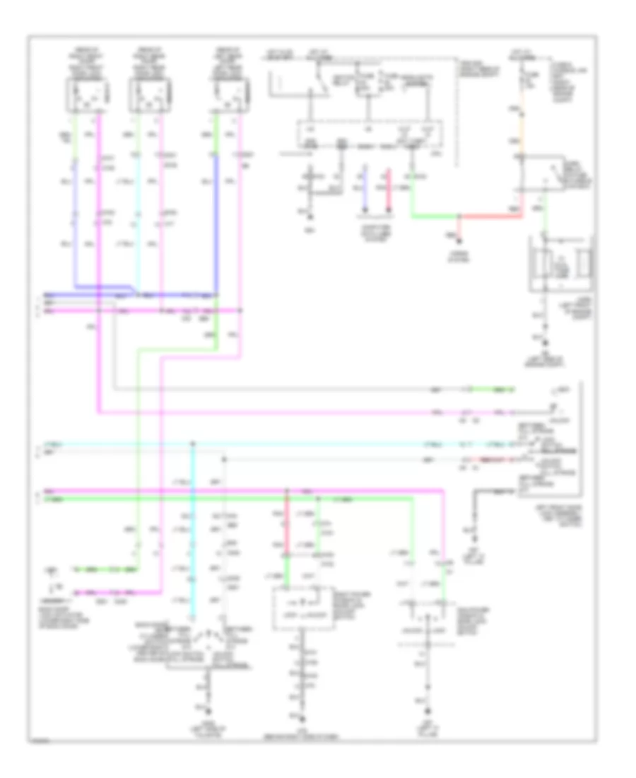
Door Lock & Keyless Entry Wiring Diagram (2 of 2) for Nissan Xterra X 2013
List of elements for Door Lock & Keyless Entry Wiring Diagram (2 of 2) for Nissan Xterra X 2013:
- (rear of left rear door) left rear door lock actuator
- (rear of right front door) right front door lock actuator
- (rear of right rear door) right rear door lock actuator
- +ig
- 53j
- 71j
- 72j
- Anti theft horn
- B106
- B163
- B48
- B69
- Back door key cylinder switch (lower right center of back door)
- Back door lock actuator (lower right side of back door)
- Between full stroke & n
- Can-h
- Can-l
- Computer data lines system
- Cpu
- D101
- D102
- D150
- D151
- D152
- D153
- D201
- D301
- D402
- D405
- D406 (left side of tailgate)
- D501
- E122
- E124
- E24
- E9 (left side of engine compt)
- Fuse & fusible link box (right rear of engine compt)
- Fuse 15a
- Fuse 20a
- Gnd (pwr)
- Gnd (sig)
- H/lp hi
- H/lp lo
- Headlights system
- Horn (left front of engine compt)
- Horn relay (in fuse & fusible link box)
- Horns system
- Hot at all times
- Hot in on or start
- Ignition relay
- Ipdm e/r (right rear of engine compt)
- Left front door lock assembly (key cylinder switch)
- Lock
- Lock switch full stroke
- M17
- M40
- M40 52j
- M57 (left "a" pillar)
- M74
- M75
- M79 (behind right side of dash)
- Main power window & door lock/ unlock switch
- Pnk
- Red
- Right power window & door lock/ unlock switch
- Unlock
- Unlock switch full stroke
- W/ dual tone horn
Door Lock Wiring Diagram (1 of 2) for Nissan Xterra X 2013
List of elements for Door Lock Wiring Diagram (1 of 2) for Nissan Xterra X 2013:
- 55g m31
- 57j
- 60j
- 61j
- B162
- B48
- B69
- Back door sw
- Back door switch (lower left center of back door)
- Bat (f/l)
- Bat (fuse)
- Bcm (under left side of dash)
- Can-h
- Can-l
- Cdl lock sw
- Cdl unlock sw
- Closed
- Computer data lines system
- D402
- D405
- D406 (left side of tailgate)
- D501
- Door sw (dr)
- Door sw (rl)
- Dr lk output (all)
- Dr sw (as)
- Dr sw (rr)
- Dr unlk output (dr)
- Dr unlk output (other)
- E10
- E152
- Fuse & fusible link box (right rear of engine compt)
- Fuse 10a
- Fuse block (j/b) (right side of dash)
- Fusible link g 50a
- Gnd (power)
- Hot at all times
- Inserted
- Key cylinder lock sw
- Key cylinder unlock sw
- Key sw
- Key switch
- Left front door switch (at left "b" pillar)
- Left rear door switch (at left "c" pillar)
- M16
- M18
- M19
- M20
- M3 4n
- M40
- M57 (left "a" pillar)
- Open
- Pnk
- Removed
- Right front door switch (at right "b" pillar)
- Right rear door switch (at right "c" pillar)
Door Lock Wiring Diagram (2 of 2) for Nissan Xterra X 2013
List of elements for Door Lock Wiring Diagram (2 of 2) for Nissan Xterra X 2013:
- (rear of left rear door) left rear door lock actuator
- (rear of right front door) right front door lock actuator
- (rear of right rear door) right rear door lock actuator
- 53j
- 71j
- 72j
- B163 m17
- B48
- B69
- Back door key cylinder switch (lower right center of back door)
- Back door lock actuator (lower right side of back door)
- Between full stroke & n
- D101
- D101 d152
- D102
- D150
- D151
- D152
- D153
- D153 m75
- D201 b6
- D301 b106
- D402
- D405
- D406 (left side of tailgate)
- D501
- Left front door lock (key cylinder switch)
- Lock
- Lock switch full stroke
- M40
- M40 52j
- M57 (left "a" pillar)
- M74
- M75
- M79 (behind right side of dash)
- Main power window & door lock/ unlock switch
- Pnk
- Right power window & door lock/ unlock switch
- Unlock
- Unlock switch full stroke
POWER MIRRORS
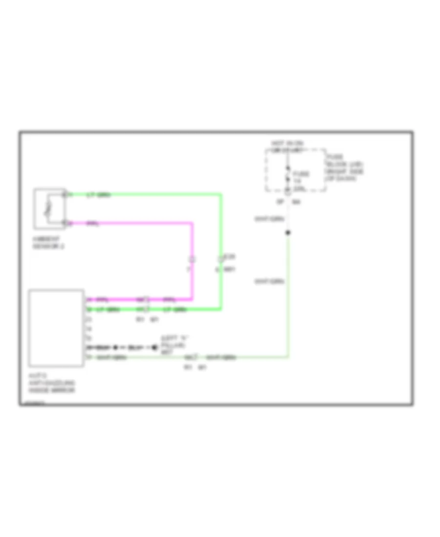
Auto Anti-dazzling Mirror Wiring Diagram for Nissan Xterra X 2013
List of elements for Auto Anti-dazzling Mirror Wiring Diagram for Nissan Xterra X 2013:
- (left "a" pillar) m57
- Ambient sensor 2
- Auto anti-dazzling inside mirror
- E26
- Fuse 10a
- Fuse block (j/b) (right side of dash)
- Hot in on or start
- M1 r1
- M91
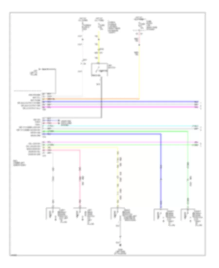
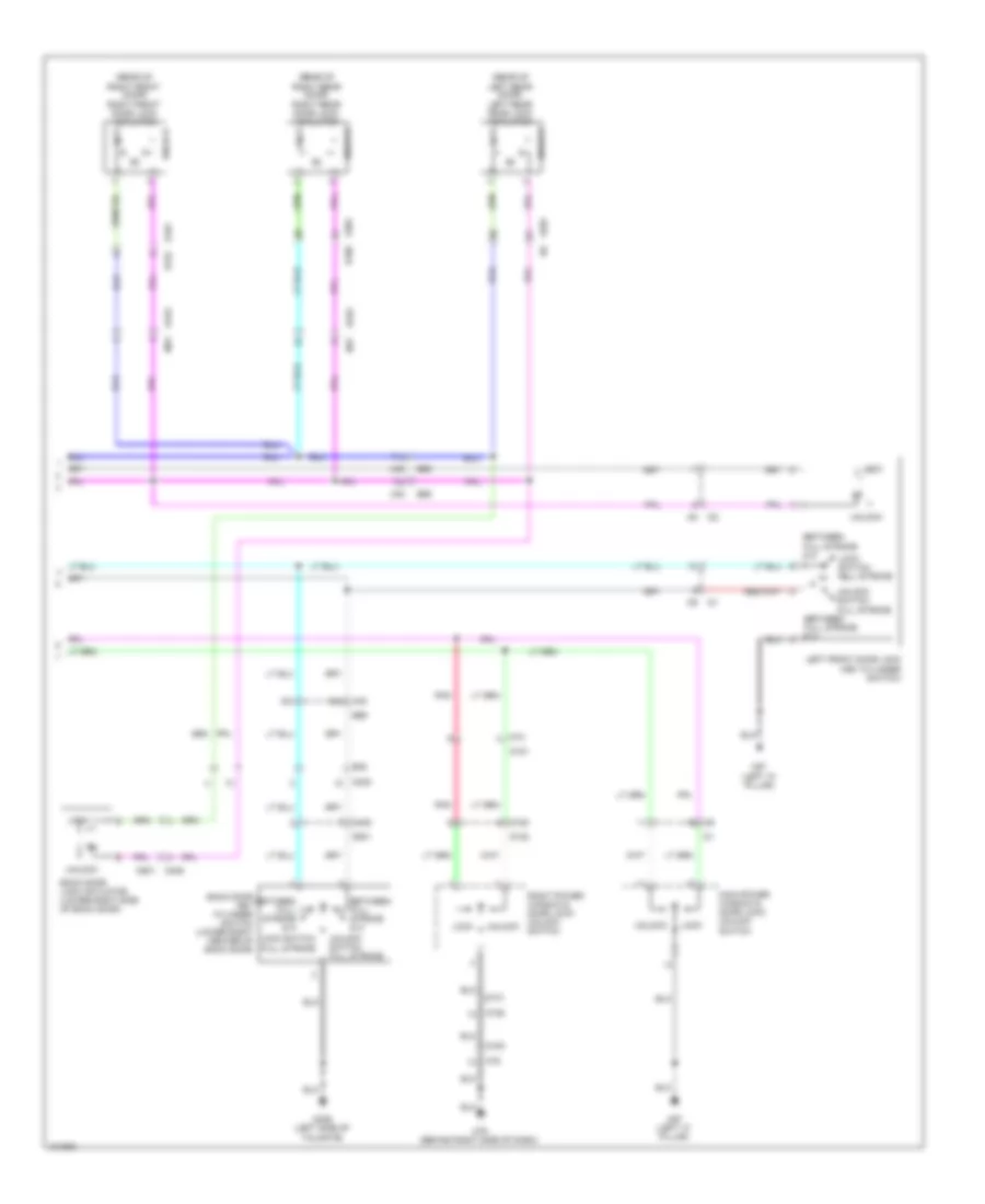
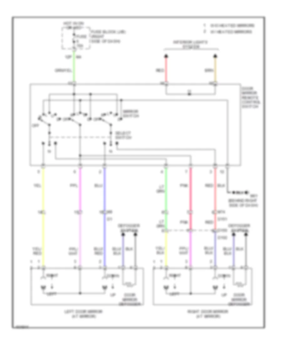
Power Mirrors Wiring Diagram for Nissan Xterra X 2013
List of elements for Power Mirrors Wiring Diagram for Nissan Xterra X 2013:
- 12p m4
- D102
- D150
- D151
- Defogger system
- Door mirror defogger
- Door mirror remote control switch
- Down
- Fuse 10a
- Fuse block (j/b) (right side of dash)
- Hot in on or acc
- Interior lights system
- Left
- Left door mirror (at mirror)
- M61 (behind right side of dash)
- M74
- Mirror switch
- Off
- Pnk
- Red
- Right
- Right door mirror (at mirror)
- Select switch
- W/ heated mirrors
- W/o heated mirrors
POWER WINDOWS
Power Windows Wiring Diagram for Nissan Xterra X 2013
List of elements for Power Windows Wiring Diagram for Nissan Xterra X 2013:
- (left "a" pillar) m57
- 61j
- 75j
- 80j
- Acc
- B106
- B117 (under front passenger's seat)
- B162
- B163
- B69
- B7 (under driver's seat)
- Bat (f/l)
- Bcm (under left side of dash)
- Can-h
- Can-l
- Computer data lines system
- Cpu
- D101
- D152
- D153
- D201
- D301
- Door sw (as)
- Door sw (dr)
- Down
- Down relay
- E10
- Express down
- Fuse & fusible link box (right rear of engine compt)
- Fuse 10a
- Fuse block (j/b) (right side of dash)
- Fusible link g 50a
- Gnd (power)
- Hot at all times
- Hot in on or acc
- Hot in on or start
- Ign
- Left front door switch (at left "b" pillar)
- Left front power window motor (center of left front door)
- Left rear power window motor (in left rear door)
- Left rear power window switch
- Lh front
- Lh rear
- Lock
- Lock switch
- M16
- M17
- M18
- M19
- M20
- M4 15p
- M40 10j
- M40 b69
- M57 (left "a" pillar)
- M75
- Main power window & door lock/ unlock switch
- Pnk
- Pwr win pwr sply (rap)
- Rap
- Red
- Rh front
- Rh rear
- Right front door switch (at right "b" pillar)
- Right front power window motor (in right front door)
- Right power window & door lock/ unlock switch
- Right rear power window motor (in right rear door)
- Right rear power window switch
- Unlock
RADIO
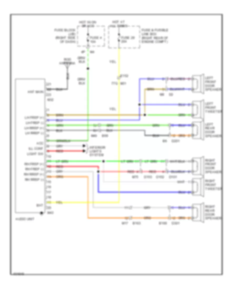
Base Radio Wiring Diagram for Nissan Xterra X 2013
List of elements for Base Radio Wiring Diagram for Nissan Xterra X 2013:
- Acc
- Ant main
- Audio unit
- B106
- B163
- B69
- Bat
- D101
- D152
- D153
- D201
- D301
- E152
- Fuse & fusible link box (right rear of engine compt)
- Fuse 29 20a
- Fuse 4 10a
- Fuse block (j/b) (right side of dash)
- Hot at all times
- Hot in on or acc
- Ill cont
- Interior lights system
- Left front door speaker
- Left front tweeter
- Left rear door speaker
- Lh frsp (+)
- Lh frsp (-)
- Lh rrsp (+)
- Lh rrsp (-)
- Light sw
- M17
- M31 77g
- M32
- M40
- M43
- M75
- Red
- Rh frsp (+)
- Rh frsp (-)
- Rh rrsp (+)
- Rh rrsp (-)
- Right front door speaker
- Right front tweeter
- Right rear door speaker
- Rod antenna
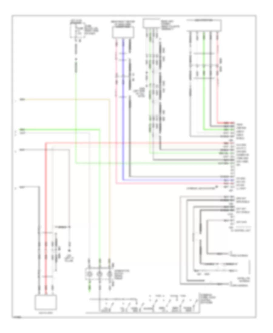
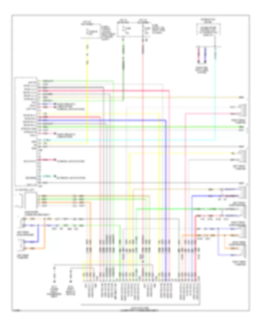
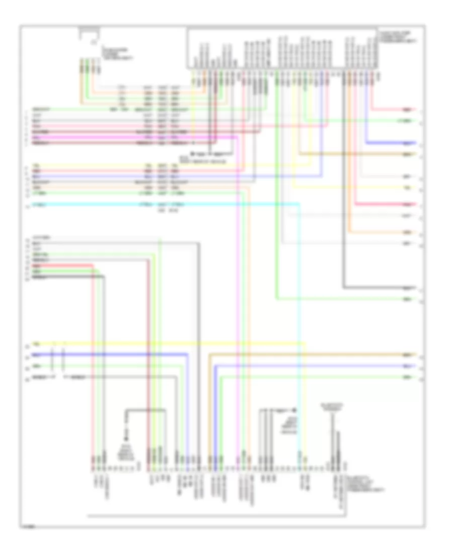
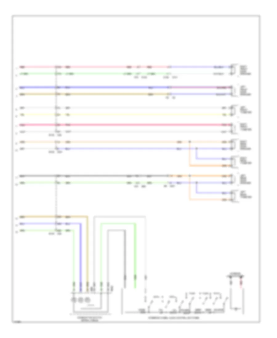
Radio Wiring Diagram, with Navigation (1 of 2) for Nissan Xterra X 2013
List of elements for Radio Wiring Diagram, with Navigation (1 of 2) for Nissan Xterra X 2013:
- 16p
- 51m
- 52m
- 54m
- 55m
- 57m
- 58m
- 60m
- 61m
- 63m
- 72m
- 73m
- 74m
- 76m
- 77m
- 78m
- 79m
- Acc
- Amp 0n/off sig
- Amp on
- Audio amplifier (under front passenger's seat)
- Aux l (+)
- Av control unit
- B106
- B117 (under front passenger's seat)
- B132 (right rear of vehicle)
- B149
- B158 gnd
- B159 frsp rh out (+)
- B159 frsp rh out (-)
- B69
- Bat
- Can-h
- Can-l
- Combination meter
- Computer data lines system
- D101
- D152
- D153
- D201
- D301
- Exterior lights system
- Fr lh tw (+)
- Fr lh tw (-)
- Fr rh tw (+)
- Fr rh tw (-)
- Fr sp lh (+)
- Fr sp lh (-)
- Fr sp rh (+)
- Fr sp rh(-)
- Frsp lh (+) in
- Frsp lh (-) in
- Frsp lh out (+)
- Frsp lh out (-)
- Frsp rh (+) in
- Frsp rh (-) in
- Fuse & fusible link box (right rear of engine compt)
- Fuse 10a
- Fuse 15a
- Fuse 29 20a
- Fuse block (j/b) (right side of dash)
- Gnd
- Hot at all times
- Hot in on or acc
- Interior lights system
- Left front door speaker
- Left front tweeter
- Left rear door speaker
- Left rear tweeter
- Light sw
- M36
- M40
- M75
- M96
- M97
- Mr output
- Pnk
- Red
- Reverse
- Right front door speaker
- Right front tweeter
- Right rear door speaker
- Right rear tweeter
- Rr sp lh (+)
- Rr sp lh (-)
- Rr sp rh (+)
- Rr sp rh (-)
- Rrsp lh (+) in
- Rrsp lh (-) in
- Rrsp lh out (+)
- Rrsp lh out (-)
- Rrsp rh (+) in
- Rrsp rh (-) in
- Rrsp rh out (+)
- Rrsp rh out (-)
- Spd
- Strg sw a
- Strg sw b
- Strg sw gnd
- Subwoofer (under driver's seat)
- Unified meter control unit (w/ information display)
- Woofer (+) 1
- Woofer (+) 2
- Woofer (-) 1
- Woofer (-) 2
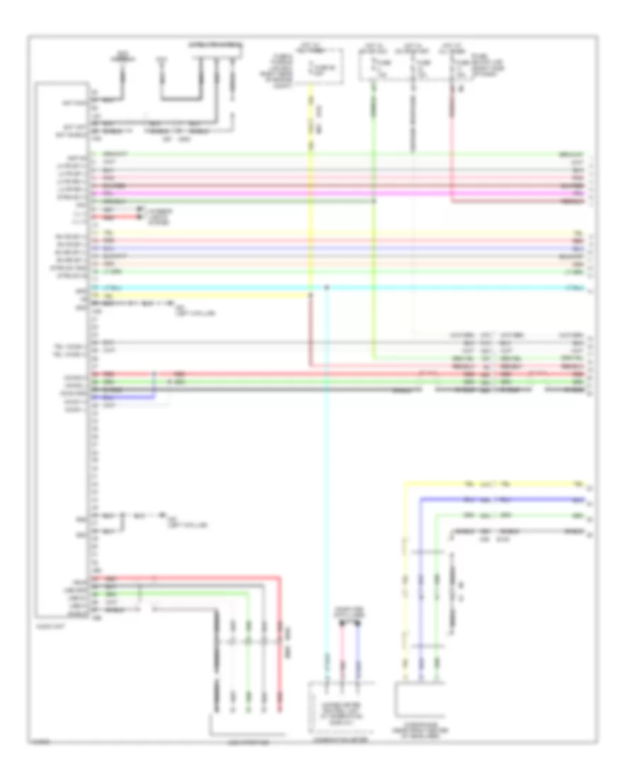
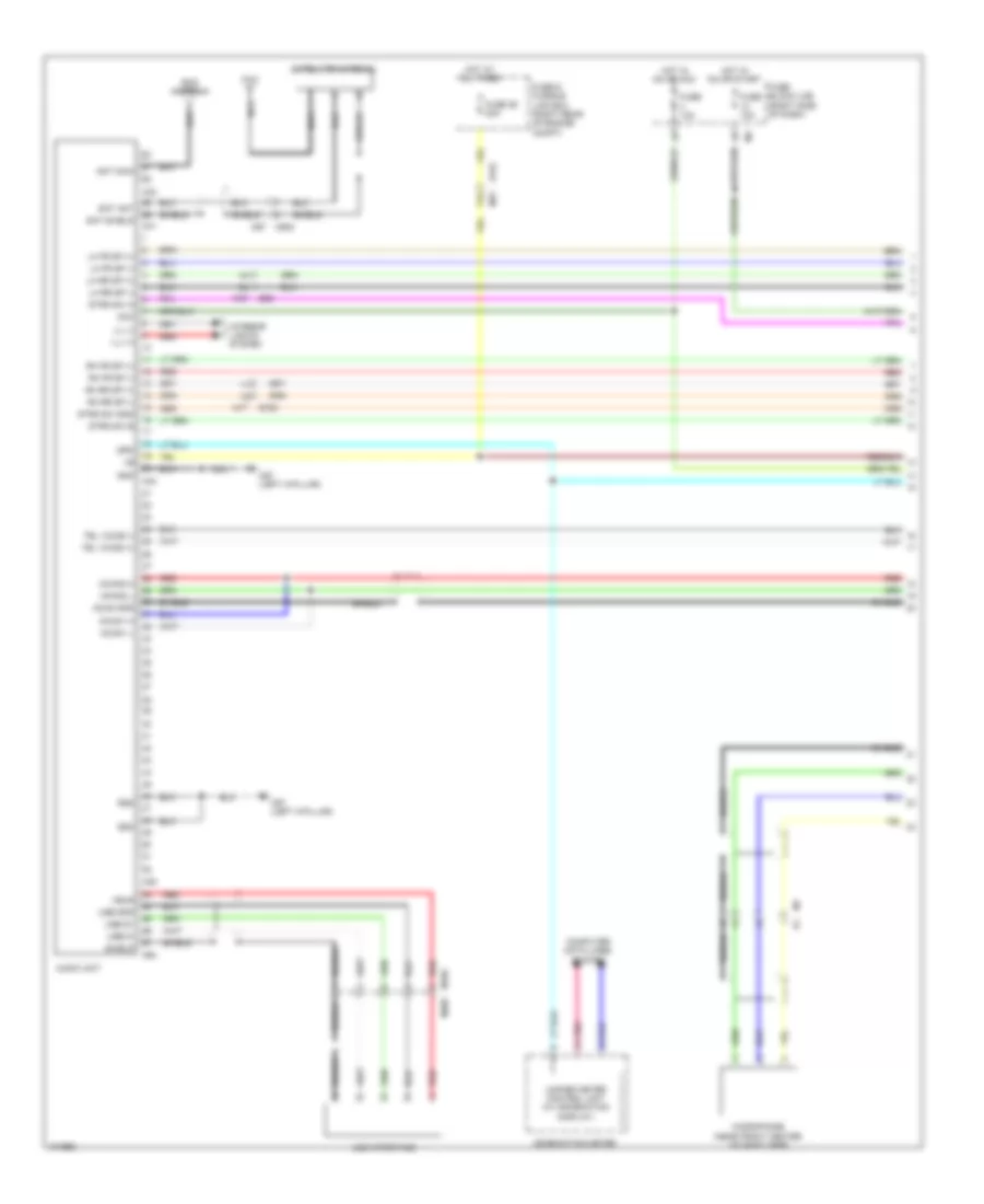
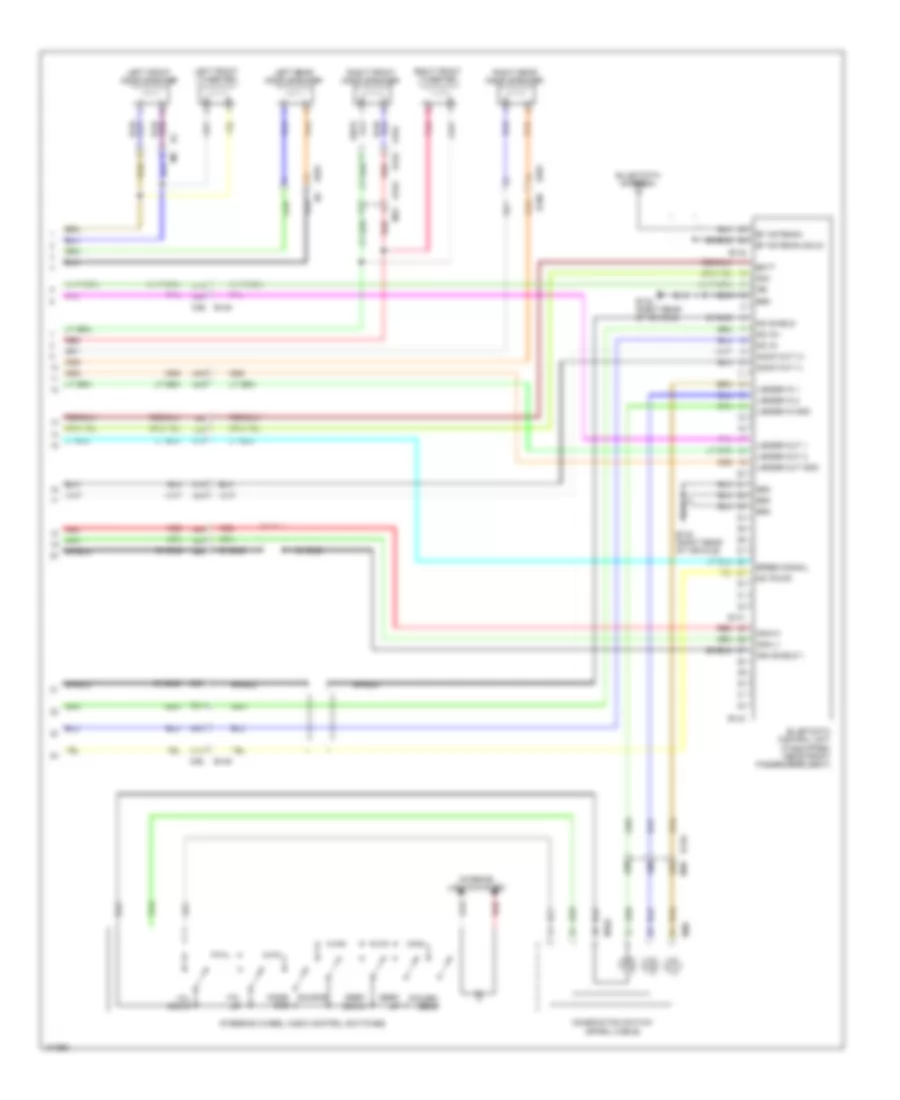
Radio Wiring Diagram, with Navigation (2 of 2) for Nissan Xterra X 2013
List of elements for Radio Wiring Diagram, with Navigation (2 of 2) for Nissan Xterra X 2013:
- (near front center of headliner) microphone
- 56j
- 65j
- 66j
- 67j
- Ant main
- Aux gnd
- Aux in jack
- Aux r (+)
- Av control unit
- B69
- Cam gnd
- Cam video
- Camera on
- Combination switch (spiral cable)
- D402 b48
- D404
- D406 (left side of tail- gate)
- D503
- Fuse 10a
- Fuse block (j/b) (right side of dash)
- Gps ant
- Gps antenna
- Gps shield
- Hot in on or start
- Ign
- Ill cont
- Interior lights system
- M100
- M102
- M169
- M204
- M205
- M30
- M38
- M40
- M500
- M57 (left "a" pillar)
- M63
- M67
- M97
- M98
- M99
- Mic gnd
- Mic sig
- Mic vcc
- Mode/ end
- Phone/ send
- Pnk
- R1 m1
- Rear view camera (rear tailgate assembly)
- Red
- Rod antenna
- Sat ant
- Sat shield
- Satellite antenna
- Seek down
- Seek up
- Shield
- Source
- Steering wheel audio control switches
- Usb d+
- Usb d-
- Usb gnd
- Usb interface
- Vbus
- Video gnd
- Vol down
- Vol up
Radio Wiring Diagram, without Navigation with Amplifier (1 of 3) for Nissan Xterra X 2013
List of elements for Radio Wiring Diagram, without Navigation with Amplifier (1 of 3) for Nissan Xterra X 2013:
- 10m
- 16p
- 31m
- 36m
- 37m
- 38m
- 39m
- 40m
- 41m
- 42m
- 49m
- 50m
- 77g
- Acc
- Amp on
- Ant main
- Audio unit
- B149
- Combination meter
- Computer data lines system
- E152
- Eq2
- Eq3
- Fuse & fusible link box (right rear of engine compt)
- Fuse 10a
- Fuse 15a
- Fuse 29 20a
- Fuse block (j/b) (right side of dash)
- Gnd
- Hot at all times
- Hot in on or acc
- Hot in on or start
- Ill (+)
- Ill (-)
- Interior lights system
- Lh fr rr (+)
- Lh fr rr (-)
- Lh fr sp (+)
- Lh fr sp (-)
- M169
- M205
- M31
- M36
- M37
- M46
- M48
- M500
- M57 (left a-pillar)
- M65
- M66
- M67
- Mcan gnd
- Mcan1 h
- Mcan1 l
- Mcan2 h
- Mcan2 l
- Microphone (near front center of headliner)
- Nca
- Pnk
- Red
- Rh fr sp (+)
- Rh fr sp (-)
- Rh rr sp (+)
- Rh rr sp (-)
- Rod antenna
- Sat ant
- Sat shield
- Satellite antenna
- Shield
- Spd
- Strg sw a
- Strg sw b
- Strg sw gnd
- Tel voice (+)
- Tel voice (-)
- Unified meter control unit (w/ information display)
- Usb d+
- Usb d-
- Usb gnd
- Usb interface
- Vbus
Radio Wiring Diagram, without Navigation with Amplifier (2 of 3) for Nissan Xterra X 2013
List of elements for Radio Wiring Diagram, without Navigation with Amplifier (2 of 3) for Nissan Xterra X 2013:
- 34m
- 43m
- 44m
- 47m
- 51m
- 52m
- 54m
- 55m
- 57m
- 58m
- 60m
- 61m
- 63m
- 73m
- 74m
- 76m
- 78m
- 79m
- Acc
- Amp on/off sig
- Audio amplifier (under front passenger's seat)
- Audio out (+)
- Audio out (-)
- B132 (right rear of
- B132 (right rear of vehicle)
- B141
- B142
- B143
- B149
- B158
- B159
- B69
- Batt
- Bt antenna
- Bt antenna shld
- Can shield 1
- Can-h1
- Can-l1
- Gnd
- Ign
- Ladder in 1
- Ladder in 2
- Ladder in gnd
- Ladder out 1
- Ladder out 2
- Ladder out gnd
- Lh fr sp (+) in
- Lh fr sp (-) in
- Lh fr sp out (+)
- Lh fr sp out (-)
- Lh fr tw (+)
- Lh fr tw (-)
- Lh rr sp (+) in
- Lh rr sp (-) in
- Lh rr sp out (+)
- Lh rr sp out (-)
- M36
- M40
- Mic in+
- Mic in-
- Mic pwr
- Mic shield
- Pnk
- Red
- Rh fr sp (+) in
- Rh fr sp (-) in
- Rh fr sp out (+)
- Rh fr sp out (-)
- Rh fr tw (+)
- Rh fr tw (-)
- Rh rr sp (+) in
- Rh rr sp (-) in
- Rh rr sp out (+)
- Rh rr sp out (-)
- Shield
- Spd sig
- Subwoofer (under driver's seat)
- Vehicle)
- Woofer (+) 1
- Woofer (+) 2
- Woofer (-) 1
- Woofer (-) 2
Radio Wiring Diagram, without Navigation with Amplifier (3 of 3) for Nissan Xterra X 2013
List of elements for Radio Wiring Diagram, without Navigation with Amplifier (3 of 3) for Nissan Xterra X 2013:
- 35m
- 45m
- 46m
- 72m
- 77m
- B106
- B149
- B69
- Combination switch (spiral cable)
- D101
- D152
- D153
- D201
- D301
- Interior lights system
- Left front door speaker
- Left front tweeter
- Left rear door speaker
- Left rear tweeter
- M102
- M30
- M36
- M40
- M75
- Mode/ end
- Pnk
- Power/ send
- Red
- Right front door speaker
- Right front tweeter
- Right rear door speaker
- Right rear tweeter
- Seek down
- Seek up
- Source
- Steering wheel audio control switches
- Vol down
- Vol up
Radio Wiring Diagram, without Navigation without Amplifier (1 of 2) for Nissan Xterra X 2013
List of elements for Radio Wiring Diagram, without Navigation without Amplifier (1 of 2) for Nissan Xterra X 2013:
- 77g
- Acc
- Ant main
- Audio unit
- B163
- B69
- Combination meter
- Computer data lines system
- E152
- Eq2
- Eq3
- Fuse & fusible link box (right rear of engine compt)
- Fuse 10a
- Fuse 29 20a
- Fuse block (j/b) (right side of dash)
- Gnd
- Hot at all times
- Hot in on or acc
- Hot in on or start
- Ill (+)
- Ill (-)
- Interior lights system
- Lh fr sp (+)
- Lh fr sp (-)
- Lh rr sp (+)
- Lh rr sp (-)
- M1 r1
- M169
- M17
- M205
- M31
- M33
- M40
- M41
- M44
- M45
- M500
- M57 (left a-pillar)
- M64
- M67
- Mcan gnd
- Mcan1 h
- Mcan1 l
- Mcan2 h
- Mcan2 l
- Microphone (near front center of headliner)
- Nca
- Pnk
- Red
- Rh fr sp (+)
- Rh fr sp (-)
- Rh rr sp (+)
- Rh rr sp (-)
- Rod antenna
- Sat ant
- Sat shield
- Satellite antenna
- Shield
- Spd
- Strg sw a
- Strg sw b
- Strg sw gnd
- Tel voice (+)
- Tel voice (-)
- Unified meter control unit (w/ information display)
- Usb d+
- Usb d-
- Usb gnd
- Usb interface
- Vbus
Radio Wiring Diagram, without Navigation without Amplifier (2 of 2) for Nissan Xterra X 2013
List of elements for Radio Wiring Diagram, without Navigation without Amplifier (2 of 2) for Nissan Xterra X 2013:
- 10m
- 31m
- 34m
- 35m
- 36m
- 37m
- 38m
- 39m
- 40m
- 41m
- 42m
- 43m
- 44m
- 45m
- 46m
- 47m
- 49m
- 50m
- Acc
- Audio out (+)
- Audio out (-)
- B106
- B132 (right rear of vehicle)
- B141
- B142
- B143
- B149
- Batt
- Bt antenna
- Bt antenna shld
- Can shield 1
- Can-h1
- Can-l1
- Combination switch (spiral cable)
- D101
- D152
- D153
- D201
- D301
- Gnd
- Ign
- Interior lights system
- Ladder in 1
- Ladder in 2
- Ladder in gnd
- Ladder out 1
- Ladder out 2
- Ladder out gnd
- Left front door speaker
- Left front tweeter
- Left rear door speaker
- M102
- M30
- M36
- M75
- Mic in+
- Mic in-
- Mic powr
- Mic shield
- Mode/ end
- Pnk
- Power/ send
- Red
- Right front door speaker
- Right front tweeter
- Right rear door speaker
- Seek down
- Seek up
- Shield
- Source
- Speed signal
- Steering wheel audio control switches
- Vol down
- Vol up
SHIFT INTERLOCK
Shift Interlock Wiring Diagram for Nissan Xterra X 2013
List of elements for Shift Interlock Wiring Diagram for Nissan Xterra X 2013:
- A/t shift selector
- E26
- Fuse 12 10a
- Fuse block (j/b) (right side of dash)
- Hot in on or start
- M61 (behind right side of dash)
- M91
- Park position switch (shift selector)
- Red
- Shift lock solenoid
- Stoplight switch (on bracket, above brake pedal)
STARTING/CHARGING
Charging Wiring Diagram for Nissan Xterra X 2013
List of elements for Charging Wiring Diagram for Nissan Xterra X 2013:
- 69g m31
- Alt c
- Avcc 1
- Battery
- Battery current sensor (right side of engine compt)
- Can h
- Can l
- Can-h
- Can-l
- Charge ind
- Combination meter
- Computer data lines system
- Cpu
- Cursen
- E122
- E128
- E152
- E16
- E201
- E202
- E203 (right side of engine)
- E206
- E209
- E40
- Ecm (right rear of engine compt)
- F14 e5
- F57
- Fuse & fusible link box (right rear of engine compt)
- Fuse 14 10a
- Fuse 15a
- Fuse block (j/b) (right side of dash)
- Fusible link a 140a
- Fusible link box (battery)
- Fusible link f 80a
- Generator
- Gnd-a
- Hot in on or start
- Ipdm e/r (intelligent power distribution module engine room) (right rear of engine compt)
- Pnk
- Red
- Unified meter control unit (w/information display)
Starting Wiring Diagram, A/T for Nissan Xterra X 2013
List of elements for Starting Wiring Diagram, A/T for Nissan Xterra X 2013:
- 45g
- A/t assembly
- Acc
- At-pn sw
- Battery
- Can h
- Can l
- Can-h
- Can-l
- Combination meter
- Computer data lines system
- Cpu
- E10
- E119
- E120
- E122
- E124
- E152 m31
- E201
- E204
- E24
- E40
- E5 red
- F14
- F502
- F503
- F505
- Fuse & fusible link box (right rear of engine compt)
- Fusible link box (battery)
- Fusible link j 40a
- Gnd (pwr)
- Gnd (sig)
- Hot at all times
- Ig1
- Ign sw
- Ignition switch
- Inhibit
- Ipdm e/r (intelligent power distribution module engine room) (right rear of engine compt)
- Off
- Pnk
- Red
- Start
- Start relay
- Starter motor
- Starter relay
- Tcm (transmission control module)
- Tr sw 1
- Tr sw 2
- Tr sw 3
- Tr sw 4
- Transmission range switch
- Unified meter control unit (w/ information display)
Starting Wiring Diagram, M/T with Clutch Interlock Cancellation for Nissan Xterra X 2013
List of elements for Starting Wiring Diagram, M/T with Clutch Interlock Cancellation for Nissan Xterra X 2013:
- 34g m31
- 39g m31
- 47g
- Acc
- Battery
- Can h
- Can l
- Cancel
- Clutch interlock cancel relay 1 (behind dash)
- Clutch interlock cancel relay 2 (in fuse & relay box)
- Clutch interlock cancel switch (on bracket, above clutch pedal)
- Clutch interlock switch (above clutch pedal)
- Computer data lines system
- Cpu
- Diode 3 (right side of engine compt)
- E10
- E119
- E120
- E122
- E124
- E152
- E201
- E204
- E24
- E40
- Fuse & fusible link box (right rear of engine compt)
- Fuse 10a
- Fusible link box (battery)
- Fusible link j 40a
- Gnd (pwr)
- Gnd (sig)
- Hot at all times
- Hot w/ ignition relay energized
- Ig1
- Ign sw
- Ignition switch
- Illumination
- Inhibit
- Interior lights system
- Ipdm e/r (intelligent power distribution module engine room) (right rear of engine compt)
- M61 (behind right side of dash)
- Motor
- Off
- Pnk
- Red
- Start
- Starter
- Starter relay
Starting Wiring Diagram, M/T without Clutch Interlock Cancellation for Nissan Xterra X 2013
List of elements for Starting Wiring Diagram, M/T without Clutch Interlock Cancellation for Nissan Xterra X 2013:
- Acc
- Battery
- Can h
- Can l
- Clutch interlock switch (above clutch pedal)
- Computer data lines system
- Cpu
- E10
- E119
- E120
- E122
- E124
- E201
- E204
- E24
- E40
- Fuse & fusible link box (right rear of engine compt)
- Fuse 10a
- Fusible link box (battery)
- Fusible link j 40a
- Gnd (pwr)
- Gnd (sig)
- Hot at all times
- Hot w/ ignition relay energized
- Ig1
- Ign sw
- Ignition switch
- Inhibit
- Ipdm e/r (intelligent power distribution module engine room) (right rear of engine compt)
- Off
- Pnk
- Red
- Start
- Starter motor
- Starter relay
SUPPLEMENTAL RESTRAINTS
Supplemental Restraints Wiring Diagram (1 of 2) for Nissan Xterra X 2013
List of elements for Supplemental Restraints Wiring Diagram (1 of 2) for Nissan Xterra X 2013:
- (at right "b" pillar)
- (behind right side of dash) m61
- (left "a" pillar) m57
- 70j
- Air bag diagnosis sensor unit (under console box)
- Air bag ind
- As1 (+)
- As1 (-)
- As2 (+)
- As2 (-)
- B113
- B157
- B162
- B69
- B78
- Buckle sw in
- Buckle sw lh
- C lh1 (+)
- C lh1 (-)
- C rh1 (+)
- C rh1 (-)
- Can-h
- Can-l
- Combination meter
- Computer data lines system
- Cut off telltale
- Dr1 (+)
- Dr1 (-), dr2 (-)
- Dr2 (+)
- Eczs (+)
- Eczs (-)
- Fuse 10a
- Fuse block (j/b) (right side of dash)
- Gnd
- Hot in on or start
- Ign
- Left sat (+)
- Left sat (-)
- Left side air bag (satellite) sensor (left of driver's seat)
- Left side curtain air bag module (near top of left "a" pillar)
- M16
- M35
- M40
- M61 (behind right side of dash)
- Ods input
- P lh1 (+)
- P lh1 (-)
- P rh1 (+)
- P rh1 (-)
- Pnk
- Rh-sat (+)
- Rh-sat (-)
- Right front seat belt pre-tensioner (base of right "b" pillar)
- Right front side air bag module (side of front passenger's seat)
- Right side air bag (satellite) sensor
- Right side curtain air bag module (near top of right "a" pillar)
- S-lh1 (+)
- S-lh1 (-)
- S-rh1 (+)
- S-rh1 (-)
- Seat belt ind
- Seat belt reminder
- Shield
- Unified meter control unit (w/ information display)
- Warn lp
Supplemental Restraints Wiring Diagram (2 of 2) for Nissan Xterra X 2013
List of elements for Supplemental Restraints Wiring Diagram (2 of 2) for Nissan Xterra X 2013:
- (behind right side of dash) (w/ service replacement) front passenger air bag module
- (behind right side of dash) front passenger air bag module
- (behind right side of dash) m61
- (under driver's seat) b7
- (under front passenger's seat) b117
- B117 (under front passenger's seat)
- B136
- B351
- Belt tension sensor (near base of right "b" pillar)
- Bts 5v
- Bts gnd
- Bts sig
- Combination switch (spiral cable)
- Comm
- Crash zone sensor (center front of engine compt)
- Driver air bag module (side of driver's seat)
- E14 (left side of engine compt)
- E29
- Front passenger air bag off indicator
- Gnd
- Ign
- Left front seat belt pre-tensioner (base of left "b" pillar)
- Left front side air bag module (side of driver's seat)
- Left seat belt buckle switch (in driver seat belt buckle assembly)
- M10
- M101
- M103
- M105
- M106
- M29
- Occupant classification system control unit (right side of vehicle)
- Occupant classification system sensor (under passenger's seat)
- Ps 5v
- Ps gnd
- Ps sig
- Red
- Right seat belt buckle switch (in front passenger seat belt buckle assembly)
- Shield
TRANSMISSION
4WD Wiring Diagram (1 of 2) for Nissan Xterra X 2013
List of elements for 4WD Wiring Diagram (1 of 2) for Nissan Xterra X 2013:
- 17g m31
- 18g
- 19g
- 20g
- 22g
- 23g
- 24g
- 25g
- 2wd sw
- 4h sw
- 4l sw
- 4lo switch (on transfer case)
- 4lpos sw
- 4wd fail ind
- 4wdposw
- 71g
- 72g
- Acc
- Actr sw1
- Actr sw2
- Actr sw3
- Actr sw4
- Atp (a/t) ind
- Atp sw
- Atp switch (on transfer case)
- Can-h
- Can-l
- Combination meter
- Computer data lines system
- Data link connector (under left side of dash)
- E15 (right front of engine compt)
- E152
- E19
- E24
- F14
- F33
- Fuse 10a
- Fuse block (j/b) (right side of dash)
- Gnd
- Hot at all times
- Hot in on or start
- Ig1
- Ign sw
- Ignition switch
- J/c m03
- Kline
- M152
- M153
- M31
- M57 (left "a" pillar)
- M61 (behind right side of dash)
- Mem b/u
- Mtr +
- Mtr -
- Mtrmon1
- Mtrmon2
- Mtrrly1
- Mtrrly2
- Neut sw
- Off
- Park/neutral position (pnp) switch (m/t) (top of transmission)
- Pnk
- Red
- Ssof
- Start
- Transfer control unit (behind left side of dash)
- Unified meter control unit (w/ information display)
- Vign
- Wait detection switch (on transfer case)
4WD Wiring Diagram (2 of 2) for Nissan Xterra X 2013
List of elements for 4WD Wiring Diagram (2 of 2) for Nissan Xterra X 2013:
- (in fuse & relay box) transfer shift high relay
- 12g m31
- 13g
- 14g
- 15g
- 16g m31
- 21g
- 2wd
- 4lo
- 4wd shift switch
- Actr sw 1
- Actr sw 2
- Actr sw 3
- Actr sw 4
- E10
- E152
- E19
- E24
- F32
- F33
- Fuse & fusible link box (right rear of engine compt)
- Fuse & relay box (right side of engine compt)
- Fuse 10a
- Fuse link j 40a
- Hot at all times
- Interior lights system
- Red
- Transfer control device (actuator motor) (on transfer case)
- Transfer shift low relay (in fuse & relay box)
- Transfer shut off relay 1 (in fuse & relay box)
- Transfer shut off relay 2 (in fuse & relay box)
A/T Wiring Diagram (1 of 2) for Nissan Xterra X 2013
List of elements for A/T Wiring Diagram (1 of 2) for Nissan Xterra X 2013:
- A/t assembly
- A/t fluid temperature sensor
- Atf pressure switch 2 (lc/b)
- Atf sen
- Can-h
- Can-l
- Computer data lines system
- Data link connector (under left side of dash)
- Direct clutch solenoid valve
- E152
- Exterior lights system
- F10 (top left side of engine)
- F14
- F502
- F503
- F504
- F505
- F506
- Gnd-1
- Gnd-2
- Input clutch solenoid valve
- Input speed sensor 1
- Input speed sensor 2
- K-line
- Line pressure solenoid valve
- M31 48g
- Our spd sen pwr
- Out spd sen
- Out spd sen gnd
- Output speed sensor
- Pnk
- Red
- Rev rly
- Start rly
- Starting/ charging system
- Tcm (transmission control module)
- Torque converter clutch solenoid valve
- Tr-sw1
- Tr-sw2
- Tr-sw3
- Tr-sw4
- Transmission range switch
- Vign
A/T Wiring Diagram (2 of 2) for Nissan Xterra X 2013
List of elements for A/T Wiring Diagram (2 of 2) for Nissan Xterra X 2013:
- 1n m3
- 1st pos switch
- 5p m4
- 76g m31
- A/t oil temp ind
- A/t shift selector
- Can-h
- Can-l
- Combination meter
- Computer data lines system
- E119
- E152
- E16
- Ecm (right rear of engine compt)
- F14
- Fuse 10a
- Fuse block (j/b) (right side of dash)
- Hot at all times
- Hot in on or start
- Ipdm e/r (right rear of engine compt)
- M57 (left "a" pillar)
- M61 (behind right side of dash)
- O/d off ind
- Od control switch
- Pnk
- Unified meter control unit (w/ information display)
Differential Lock Wiring Diagram for Nissan Xterra X 2013
List of elements for Differential Lock Wiring Diagram for Nissan Xterra X 2013:
- 13p
- 23c
- 24c
- 35g
- 8c c1
- C115
- C115 c14
- C14
- Can-h
- Can-l
- Combination meter
- Computer data lines system
- Diff lock cu
- Diff lock cu (back up)
- Diff lock high
- Diff lock ind
- Diff lock low
- Diff lock sw
- Diff lock sw (off)
- Diff lock sw (on)
- Differential lock control unit (under center of dash)
- Differential lock mode switch
- Differential lock position switch (under rear of vehicle)
- Differential lock solenoid (under rear of vehicle)
- E152
- E24
- E41
- Fuse 10a
- Fuse block (j/b) (right side of dash)
- Gnd
- Gnd back up
- Hot at all times
- Hot in on or start
- Interior lights system
- M31
- M4 5p
- Pnk
- Red
- Sss
WARNING SYSTEMS
Warning Systems Wiring Diagram for Nissan Xterra X 2013
List of elements for Warning Systems Wiring Diagram for Nissan Xterra X 2013:
- 15p
- 55g m31
- 61j
- 68j
- 70j
- Air bag diagnosis sensor unit (under console box)
- B69
- B7 (under driver's seat)
- Bat (f/l)
- Bcm (body control module) (under left side of dash)
- Brake ind
- Buckle sw
- Buzzer
- Can-h
- Can-l
- Combination meter
- Combination switch (lighting & turn signal switch)
- Computer data lines system
- Door ajar ind
- Door sw (dr)
- E10
- E152
- Fuse & fusible link box (right rear of engine compt)
- Fuse 10a
- Fuse block (j/b) (right side of dash)
- Fusible link g 50a
- Gnd
- Gnd pwr
- Headlights system
- Hot at all times
- Hot in on or start
- Ign sw
- Input 1
- Input 2
- Input 3
- Input 4
- Input 5
- Key sw
- Key switch
- Keyless & auto lt sens gnd
- Left front door switch (at left b-pillar)
- Left seat belt buckle switch (in driver seat belt buckle assembly)
- M18
- M19
- M20
- M28
- M35
- M40
- M57 (left a- pillar)
- Output 1
- Output 2
- Output 3
- Output 4
- Output 5
- Parking brake switch (on base of parking brake lever)
- Pnk
- Pwr
- Red
- Remote keyless entry receiver (behind right side of dash)
- Seat belt
- Seat belt ind
- Signal
- Sply out
- Tire pressure ind
- Tire pressure warning check connector (under left side of dash)
- Tpms mode trigger sw
- Unified meter control unit (w/ information display)
WIPER/WASHER
Front Wiper/Washer Wiring Diagram for Nissan Xterra X 2013
List of elements for Front Wiper/Washer Wiring Diagram for Nissan Xterra X 2013:
- 70g m31
- 79g
- Batt
- Bcm (body control module) (under left side of dash)
- Can-h
- Can-l
- Combination meter
- Combination switch (wiper & washer switch)
- Computer data lines system
- Cpu
- E121
- E122
- E152
- E24
- E9 (left side of engine compt)
- Front & rear washer motor (right rear of engine compt)
- Front wiper high relay
- Front wiper motor (left side of firewall)
- Front wiper relay
- Fuse 10a
- Fuse 20a
- Fuse 30a
- Fuse block (j/b) (right side of dash)
- Gnd (power)
- High
- Hot at all times
- Hot in on or start
- Ign sw
- Ignition relay
- Input 1
- Input 2
- Input 3
- Input 4
- Input 5
- Ipdm e/r (intelligent power distribution engine module) (right rear of engine compt)
- Low
- M18
- M20
- M28
- M31 78g
- M4 15p
- M57 (left "a" pillar)
- Move
- Output 1
- Output 2
- Output 3
- Output 4
- Output 5
- Pnk
- Red
- Stop
- Unified meter control unit (w/ information display)
- Washer fluid level switch (if equipped) (right side of engine compt)
- Washer fluid sw
- Washer ind
Rear Wiper/Washer Wiring Diagram for Nissan Xterra X 2013
List of elements for Rear Wiper/Washer Wiring Diagram for Nissan Xterra X 2013:
- 15p
- 73j m40
- 74j
- 78g
- 79g
- B48
- B69
- Bcm (body control module) (under left side of dash)
- Can-h
- Can-l
- Combination switch (wiper & washer switch)
- Computer data lines system
- D402
- D405 d501
- D406 (left side of tailgate)
- E152
- Front & rear washer motor (right rear of engine compt)
- Fuse 1 10a
- Fuse 15 10a
- Fuse block (j/b) (right side of dash)
- Gnd (power)
- Hot in on or start
- Ign sw
- Input 1
- Input 2
- Input 3
- Input 4
- Input 5
- M18
- M19
- M20
- M28
- M31
- M57 (left "a" pillar)
- Output 1
- Output 2
- Output 3
- Output 4
- Output 5
- Pnk
- Rear wiper motor (at center of back door)
- Red
- Rr wiper auto stop sw 1
- Rr wiper mtr out 1

 Čeština
 Dansk
Dansk Deutsch
 Ελληνικά
 English
 English
 Español
 Suomi
Suomi Français
 Français
 עברית
עברית Hrvatski
 Magyar
 Italiano
 日本語
日本語 한국어
한국어 Nederlands
 Polski
 Português
 Português
 Română
 Русский
 Slovenčina
 Svenska
 Türkçe
 中文 (中国)