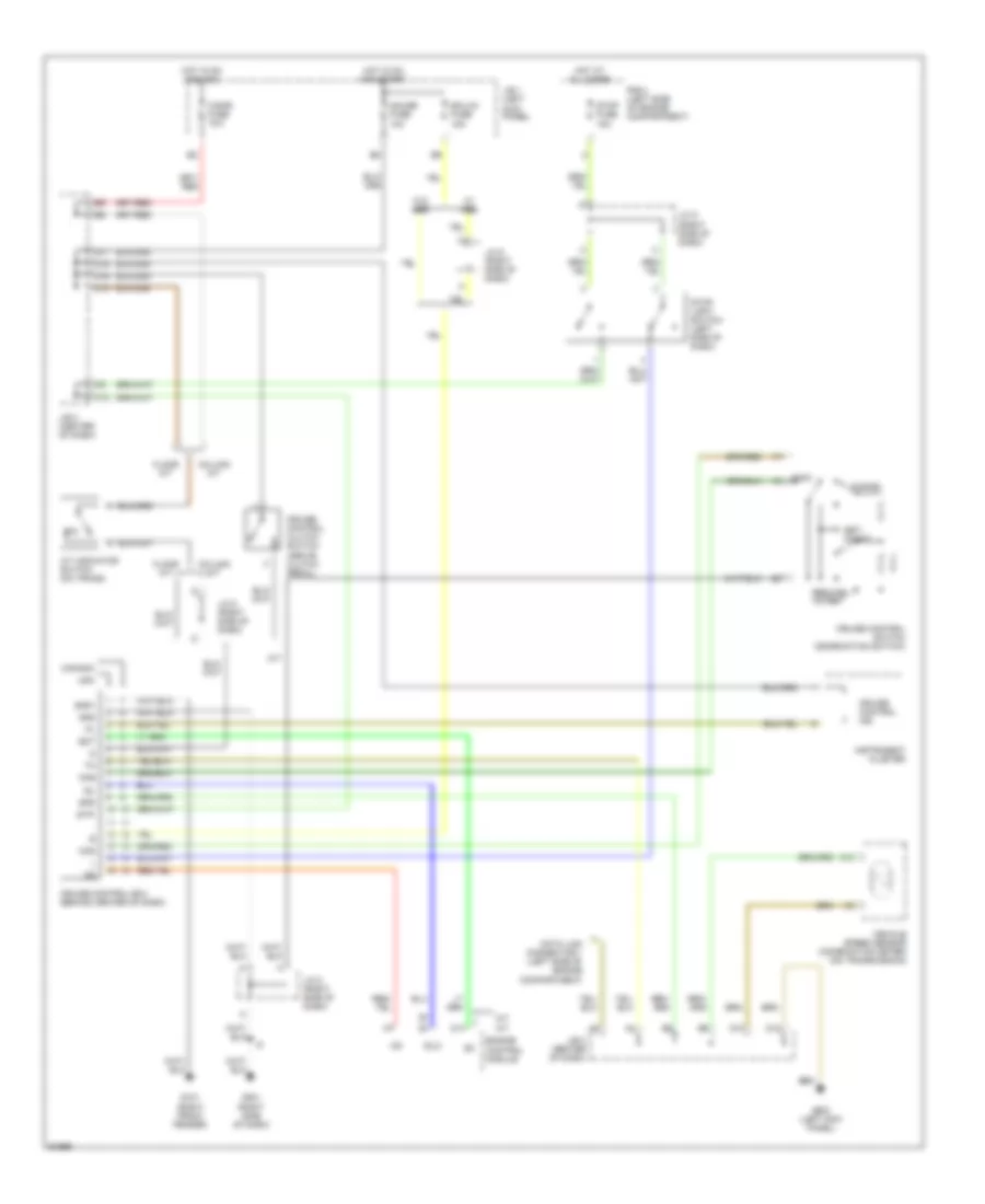
AIR CONDITIONING
A/C Wiring Diagram for Toyota Tacoma 1997
 https://portal-diagnostov.com/license.html
Automotive Electricians Portal FZCO
Automotive Electricians Portal FZCO
https://portal-diagnostov.com/license.html
https://portal-diagnostov.com/license.html
Automotive Electricians Portal FZCO
Automotive Electricians Portal FZCO
List of elements for A/C Wiring Diagram for Toyota Tacoma 1997:
- (3.4l m/t canada)
- (cowl harness, at right kick panel)
- (cowl harness, behind top right side of i/p)
- (except 3.4l m/t canada)
- 1995 vftc c
- 2.4l, 2.7l m/t
- 2.7l a/t
- 3.4l a/t
- 3.4l m/t
- 40a
- A/c amplifier (right side of i/p)
- A/c dual pressure switch (center of i/p)
- A/c fuse 10a
- A/c magnetic clutch
- A/c switch
- A/c thermistor (right side of i/p)
- A20
- Alt fuse 80a
- Blower motor
- Blower resistor (right side of i/p)
- Defroster mode switch
- E10
- Engine control module (behind right side of i/p)
- F14
- F15
- F16
- F20
- G100 (front left fender)
- G200 (left kick panel)
- G203 (right kick panel)
- Gauge fuse 10a
- Heater blower switch
- Heater fuse
- Heater relay
- Hot at all times
- Hot in run or start
- I11
- I13
- I14 (a/c harness, below glove box)
- I5 (cowl harness, behind left top of i/p)
- J/b 1 (left kick panel)
- J/b 3 (behind center of i/p)
- J/b 3 (behind center of instrument panel)
- J/c 1 (right front of engine compt)
- Off
- R/b 2 (left side of engine compt)
- Red
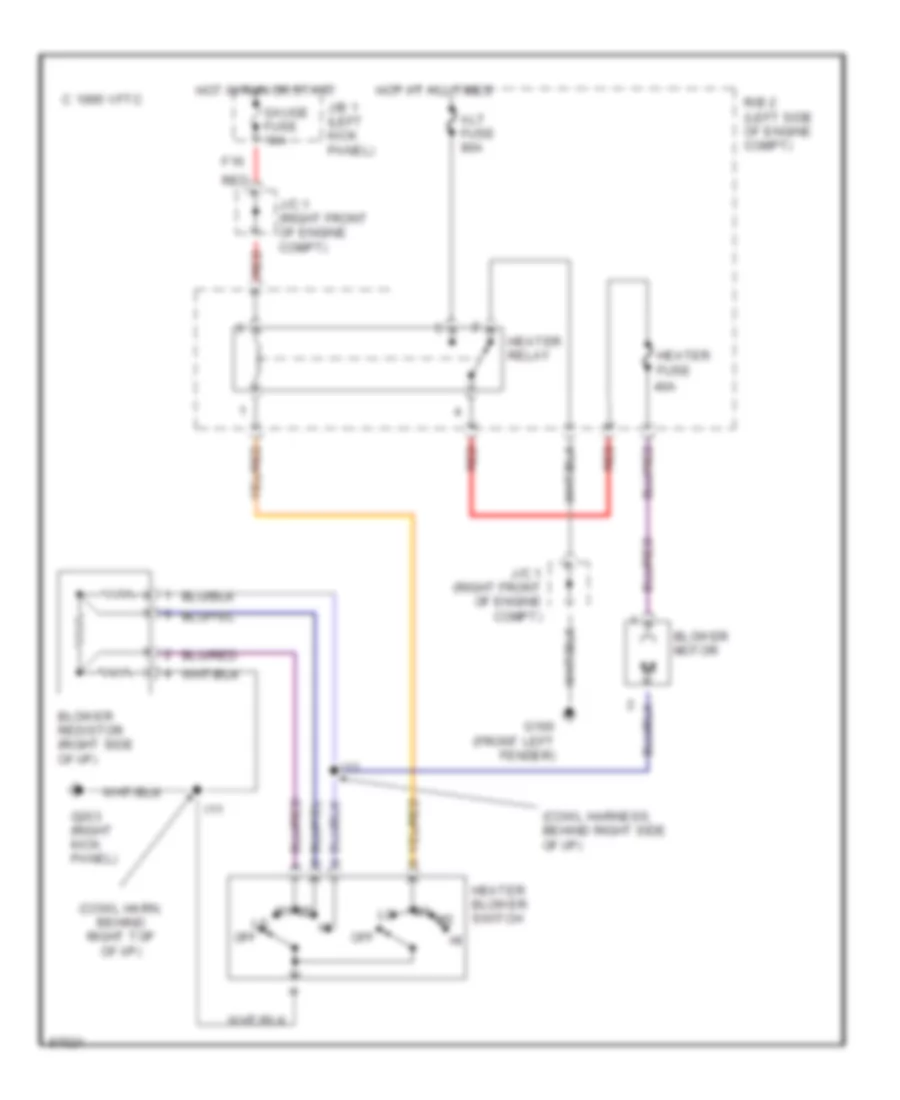
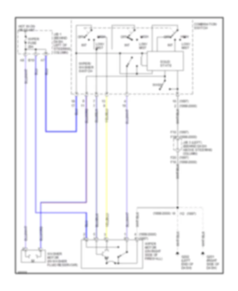
Heater Wiring Diagram for Toyota Tacoma 1997
List of elements for Heater Wiring Diagram for Toyota Tacoma 1997:
- (cowl harn, behind right top of i/p)
- (cowl harness, behind right side of i/p)
- 1995 vftc c
- 40a
- Alt fuse 80a
- Blower motor
- Blower resistor (right side of i/p)
- F16
- G100 (front left fender)
- G203 (right kick panel)
- Gauge fuse 10a
- Heater blower switch
- Heater fuse
- Heater relay
- Hot at all times
- Hot in run or start
- I11
- I13
- J/b 1 (left kick panel)
- J/c 1 (right front of engine compt)
- Off
- R/b 2 (left side of engine compt)
- Red
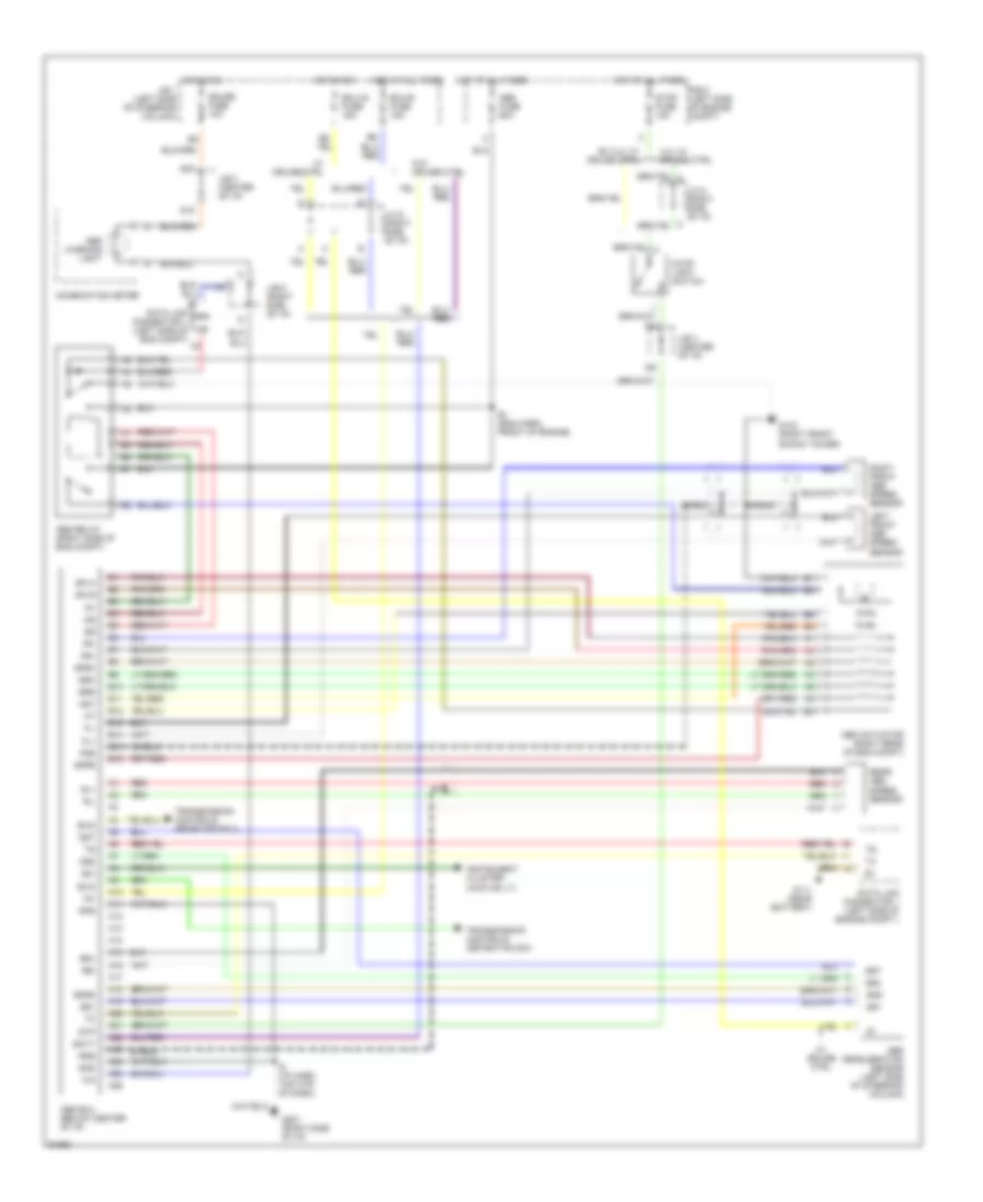
ANTI-LOCK BRAKES
Anti-lock Brake Wiring Diagrams for Toyota Tacoma 1997
List of elements for Anti-lock Brake Wiring Diagrams for Toyota Tacoma 1997:
- 3.4l w/ cruise ctrl
- A10
- A11
- A12
- A13
- A14
- A15
- A16
- A17
- A18
- A19
- A20
- A21
- A22
- A23
- A24
- A25
- A26
- Abs actuator (right rear of eng compt)
- Abs deceleration sensor (left side of steering column)
- Abs ecu (below center of i/p)
- Abs fuse 60a
- Abs relay (right side of eng compt)
- Abs warning light
- Ast
- B10
- B11
- B12
- B13
- B14
- B15
- B16
- Batt
- Combination meter
- D15
- D17
- Data link connector 1 (left side of eng compt)
- Data link connector 1 (left side of engine compt.)
- E1 (eng harn, front of engine)
- Ecu-b fuse 15a
- Ecu-ig fuse 15a
- Ex 3.4l w/ cruise ctrl
- Exi
- Exi2
- Exi3
- Fl+
- Fl-
- Fr+
- Fr-
- Fss
- G103 (right front shock tower)
- G111 (near battery)
- G201 (right side of i/p)
- Gauge fuse 10a
- Ggnd
- Gnd
- Gs1
- Gs2
- Gst
- Hot at all times
- Hot in on
- I6 (i/p harn, top ctr of dash)
- Ig1
- Instrument cluster (4wd ind lt)
- J/b 1 (left side of steering column)
- J/b 3 (center of i/p)
- J/b 6 (right side of i/p)
- J/c 6 (right side of i/p)
- J/c 8 (right side of i/p) c
- Left front abs speed sensor
- R/b 2 (left side of engine compt)
- Rear abs speed sensor
- Red
- Right front abs speed sensor
- Rl+
- Rl-
- Rr+
- Rr-
- Rss
- Sflh
- Sflr
- Sfrh
- Sfrr
- Shield
- Srh
- Srr
- Stop fuse 15a
- Stop light switch
- Stp
- Transmission controls (detection sw)
- Transmission controls (rear diff ecu)
- W/ cruise ctrl
- W/o cruise ctrl
COMPUTER DATA LINES
Computer Data Lines for Toyota Tacoma 1997
List of elements for Computer Data Lines for Toyota Tacoma 1997:
- (2.4l) --
- (2.7l) --
- (3.4l a/t) a18
- (3.4l m/t) a19
- (3.4l)
- (canada)
- (ex 3.4l)
- (i/p harn, right side of dash) i9
- (usa)
- A12
- A19
- A20
- A22
- A25
- Abs ecu (below center of dash)
- Abs ind
- Abs relay (on right side of engine compt)
- Airbag sensor assembly (below center of dash)
- B16
- Bat
- C15
- Circuit opening relay
- Combination meter
- Cruise control actuator/ecu (3.4l only) (right side of engine compt)
- Cruise control ecu (2.7/2.4l) (right kick panel)
- D13
- D15
- D17
- D24
- Data link connector 1 (on left side of engine compt)
- Data link connector 3 (below left center of dash)
- E12
- E13
- E14
- E15
- E2 (engine harness, left of battery)
- Ecu-b fuse 15a
- Efi relay
- Engine control module (below right side of dash)
- Engine controls system
- G111 (near battery)
- G201 (right side of dash)
- Gauge fuse 10a
- Hot at all times
- Hot in on or start
- I10
- I10 (i/p harn, right side of dash)
- J/b 1 (behind dash, left of steering column)
- J/b 3 (behind dash, above steering column)
- J/c 6 (below right side of dash)
- Obd fuse 10a
- R/b 2 (on left side of engine compt)
- Sdl
- Shield
- Sil
- Srs ind
- Te1
CRUISE CONTROL
2.4L
2.4L, Cruise Control Wiring Diagram for Toyota Tacoma 1997
List of elements for 2.4L, Cruise Control Wiring Diagram for Toyota Tacoma 1997:
- (2.4l)
- (2.7l)
- (a/t)
- (m/t)
- Batt
- C10
- Cancel
- Ccs
- Cms
- Cruise control actuator (on right inner fender panel)
- Cruise control clutch switch (on bracket, above clutch pedal)
- Cruise control ecu (behind center of dash)
- Cruise control ind
- Cruise control switch (combination switch)
- D10
- D12
- D15
- D16
- D17
- Data link connector 1 (left side of engine compartment)
- Ect
- Ecu-b fuse 15a
- Ecu-ig fuse 15a
- Engine controls system (throttle position sensor, engine control module)
- G200 (left kick panel)
- G201 (right side of dash)
- Gauge fuse 10a
- Gnd
- Hot at all times
- Hot in on and start
- Idl
- Igb
- Instrument cluster
- J/b 1 (left kick panel)
- J/b 3 (behind center of dash)
- J/c 3 (behind center of dash)
- J/c 6 (right side of dash)
- J/c 8 (right side of dash)
- Main
- R/b 2 (left side of engine compartment)
- Red
- Resume/ accel
- Set/ coast
- Spd
- Starting/charging system (park/neutral position switch)
- Stop fuse 15a
- Stop light switch (left side of dash)
- Stp-
- Vehicle speed sensor (combination meter) (on transmission)
- Vr1
- Vr2
- Vr3
- W/ abs
- W/o abs
2.7L
2.7L, Cruise Control Wiring Diagram for Toyota Tacoma 1997
List of elements for 2.7L, Cruise Control Wiring Diagram for Toyota Tacoma 1997:
- (2.4l)
- (2.7l)
- (a/t)
- (m/t)
- Batt
- C10
- Cancel
- Ccs
- Cms
- Cruise control actuator (on right inner fender panel)
- Cruise control clutch switch (on bracket, above clutch pedal)
- Cruise control ecu (behind center of dash)
- Cruise control ind
- Cruise control switch (combination switch)
- D10
- D12
- D15
- D16
- D17
- Data link connector 1 (left side of engine compartment)
- Ect
- Ecu-b fuse 15a
- Ecu-ig fuse 15a
- Engine controls system (throttle position sensor, engine control module)
- G200 (left kick panel)
- G201 (right side of dash)
- Gauge fuse 10a
- Gnd
- Hot at all times
- Hot in on and start
- Idl
- Igb
- Instrument cluster
- J/b 1 (left kick panel)
- J/b 3 (behind center of dash)
- J/c 3 (behind center of dash)
- J/c 6 (right side of dash)
- J/c 8 (right side of dash)
- Main
- R/b 2 (left side of engine compartment)
- Red
- Resume/ accel
- Set/ coast
- Spd
- Starting/charging system (park/neutral position switch)
- Stop fuse 15a
- Stop light switch (left side of dash)
- Stp-
- Vehicle speed sensor (combination meter) (on transmission)
- Vr1
- Vr2
- Vr3
- W/ abs
- W/o abs
3.4L
3.4L, Cruise Control Wiring Diagram for Toyota Tacoma 1997
List of elements for 3.4L, Cruise Control Wiring Diagram for Toyota Tacoma 1997:
- A/t
- A/t indicator switch (on trans)
- C10
- Canada
- Cancel
- Ccs
- Cigar fuse 15a
- Cms
- Column a/t
- Cruise control clutch switch (above clutch pedal)
- Cruise control ecu (behind center of dash)
- Cruise control ind
- Cruise control switch (combination switch)
- D10
- D12
- D14
- D15
- D16
- D17
- Data link connector 1 (left side of engine compartment)
- Ect
- Ecu-ig fuse 15a
- Engine control module
- Floor a/t
- G101 (right front fender)
- G200 (left kick panel)
- G201 (right side of dash)
- Gauge fuse 10a
- Gnd
- Gnd1
- Hot at all times
- Hot in on and acc
- Hot in on and start
- Idl
- Idlo
- Instrument cluster
- J/b 1 (left kick panel)
- J/b 3 (center of dash)
- J/c 6 (right side of dash)
- J/c 8 (right side of dash)
- M/t
- Main
- P/n
- R/b 2 (left side of engine compartment)
- Resume/ accel
- Set/ coast
- Spd
- Stop fuse 15a
- Stop light switch (left side of dash)
- Stp-
- Usa
- Vehicle speed sensor (combination meter) (on transmission)
- W/ abs
- W/o abs
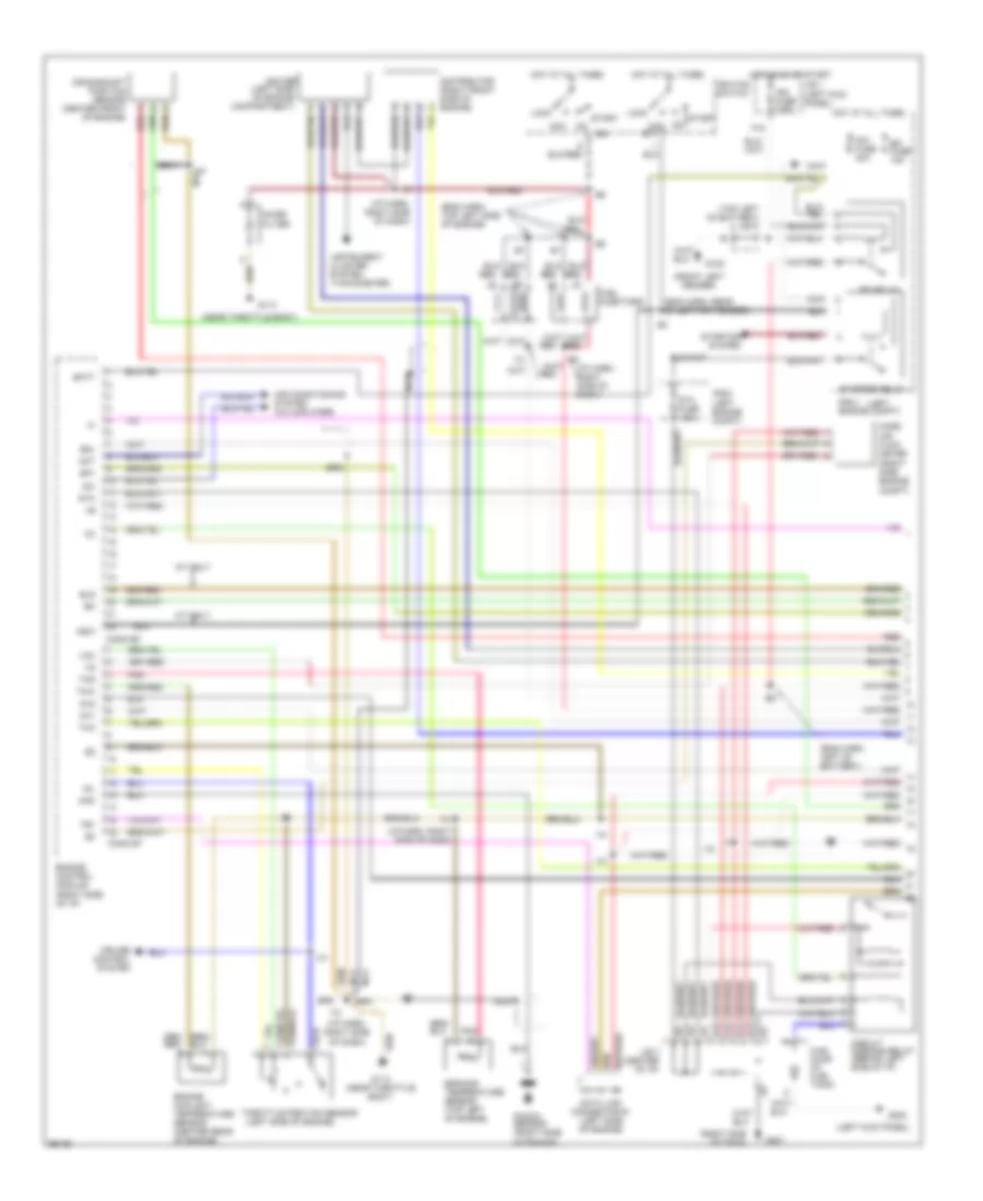
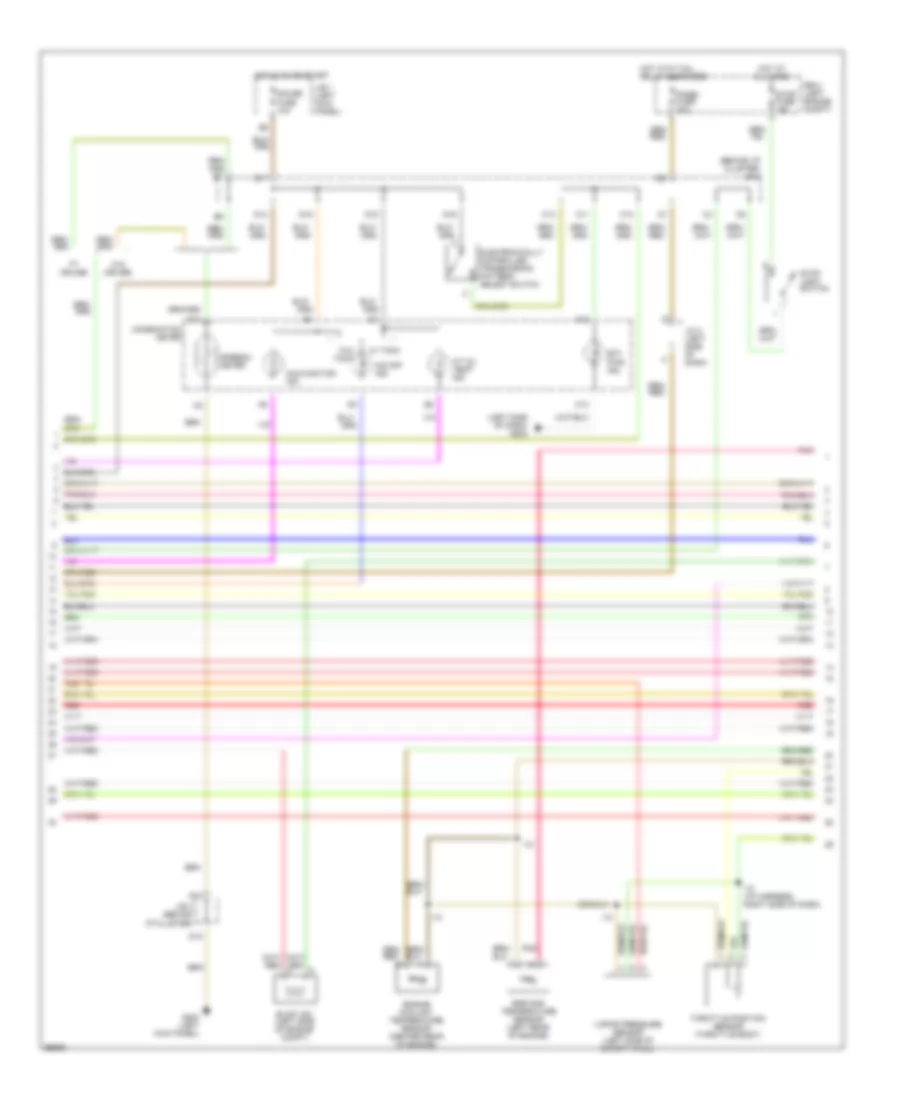
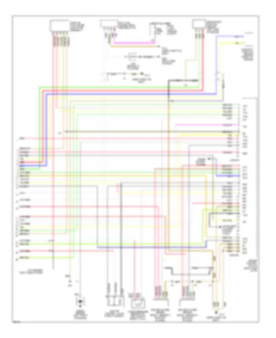
ENGINE PERFORMANCE
2.4L
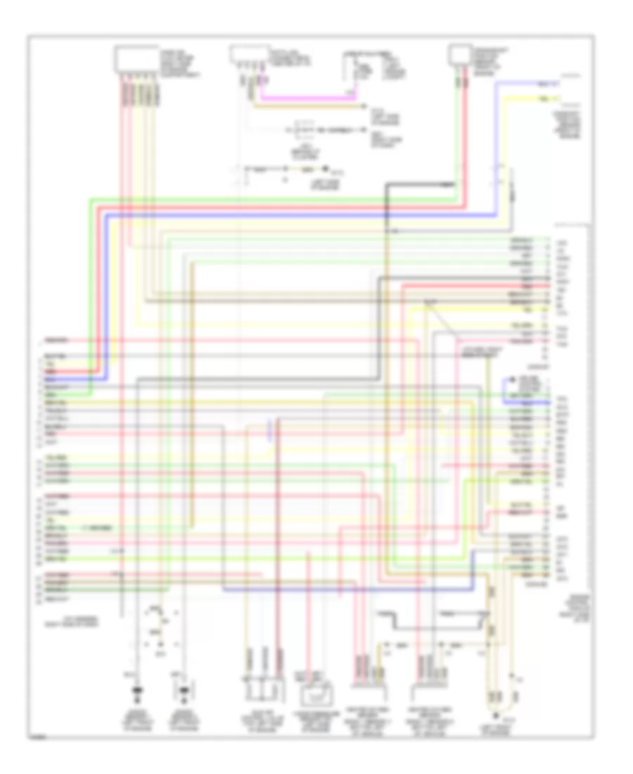
2.4L, Engine Performance Wiring Diagrams (1 of 2) for Toyota Tacoma 1997
List of elements for 2.4L, Engine Performance Wiring Diagrams (1 of 2) for Toyota Tacoma 1997:
- (eng harn, left of battery)
- (eng harn, rear of left frt fender)
- (eng harn, top left side of engine)
- (front left fender)
- (i/p harn, right side of dash)
- (left
- (left engine compt)
- (left kick panel)
- (left side of engine compartment)
- (left side of engine)
- (near throttle body)
- (right side of dash)
- (tachometer)
- (top left of battery) j/c 1
- A/t only
- Acc
- Acc st1
- Aci
- Act
- Air conditioning system (a/c amplifier)
- Am1 fuse 40a
- Batt
- Circuit opening relay (behind left side of i/p)
- Cluster system
- Conn e5
- Conn e7
- Crankshaft position sensor (center front of engine)
- Cruise control system
- Data link connector #1 (left side of engine)
- Distributor (right front side of engine)
- E12
- E13
- E14
- E15
- Efi fuse 15a
- Efi relay
- Egr gas temperature sensor (top left of engine)
- Els
- Engine control module (right side of i/p)
- Engine coolant temperature sensor (center rear of engine)
- F15
- Fuel injectors
- Fuel pump (in fuel tank)
- G102
- G113
- G113 (near throttle body)
- G201
- G202
- Hot at all times
- Hot in on or start
- I10
- Idl
- Ig2
- Ign fuse 7.5a
- Igniter
- Ignition switch
- Instrument
- J/b 1 (left kick panel)
- J/b 3 (center of i/p)
- Knk
- Knock sensor (right side of engine)
- Lock
- Mass air flow meter (right side engine compt)
- Nca
- Noise filter
- Nsw
- Ox1
- Ox2
- Pnk
- R/b 2
- R/b 2 engine compt)
- Red
- Sdl
- Sp1
- Sta
- Sta fuse 7.5a
- Start
- Starter relay
- Starting
- System
- Te1
- Tha
- Thg
- Throttle position sensor
- Thw
- Vcc
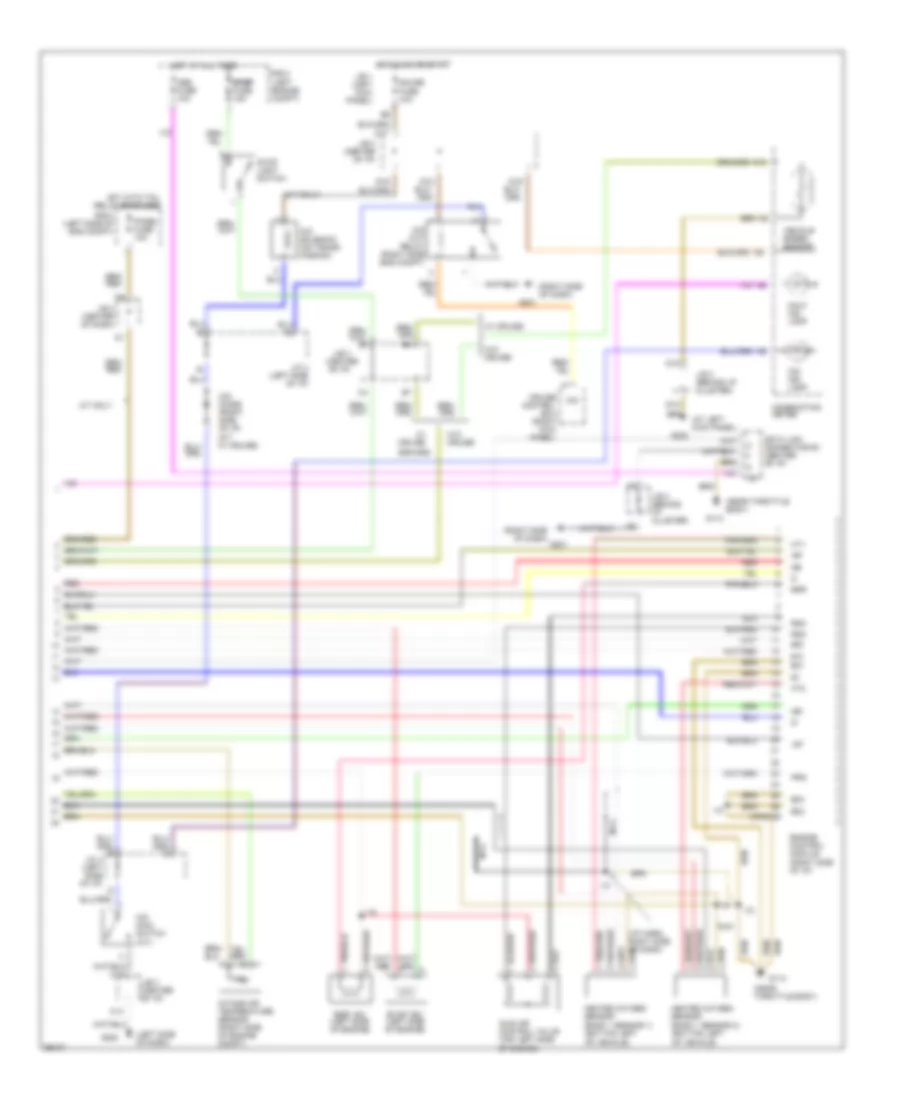
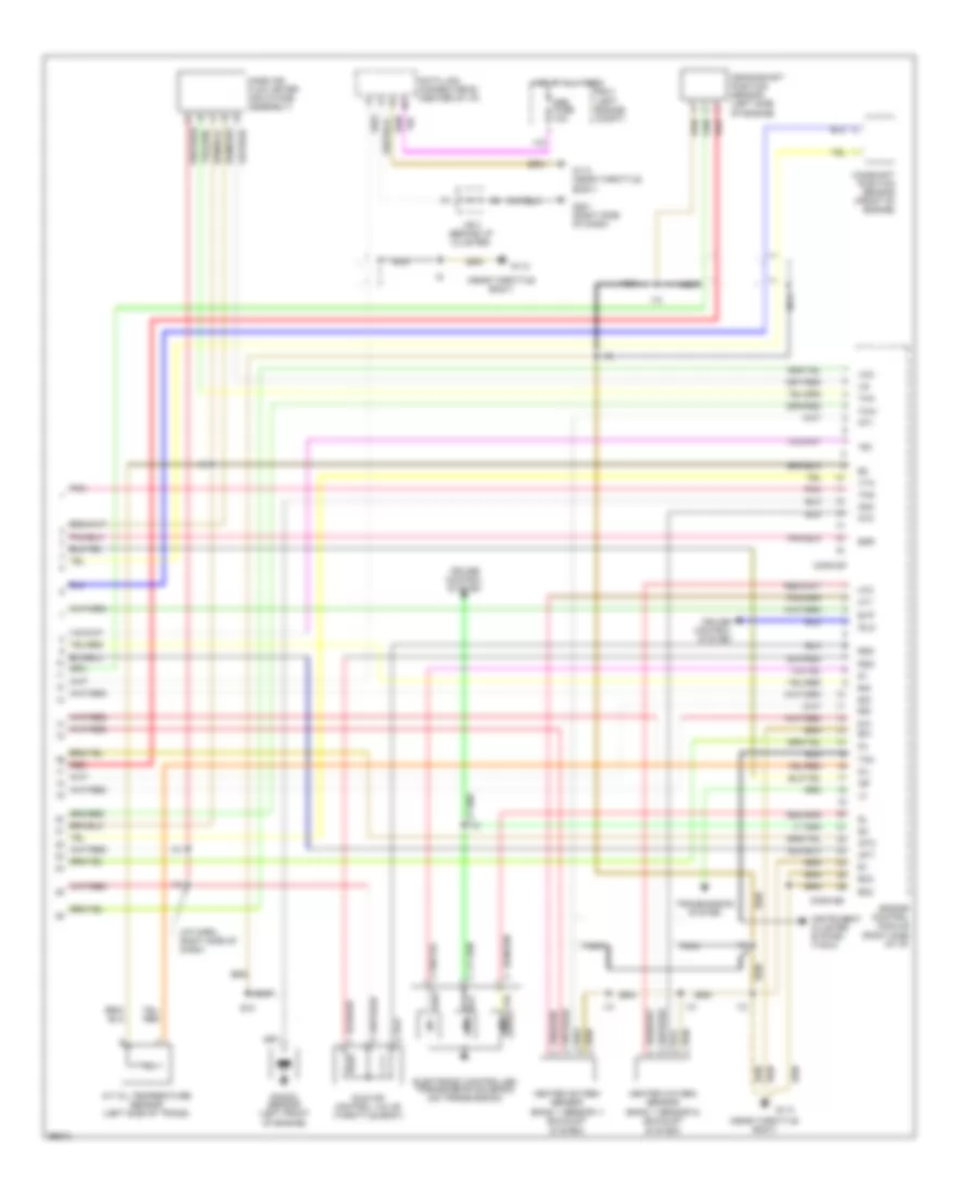
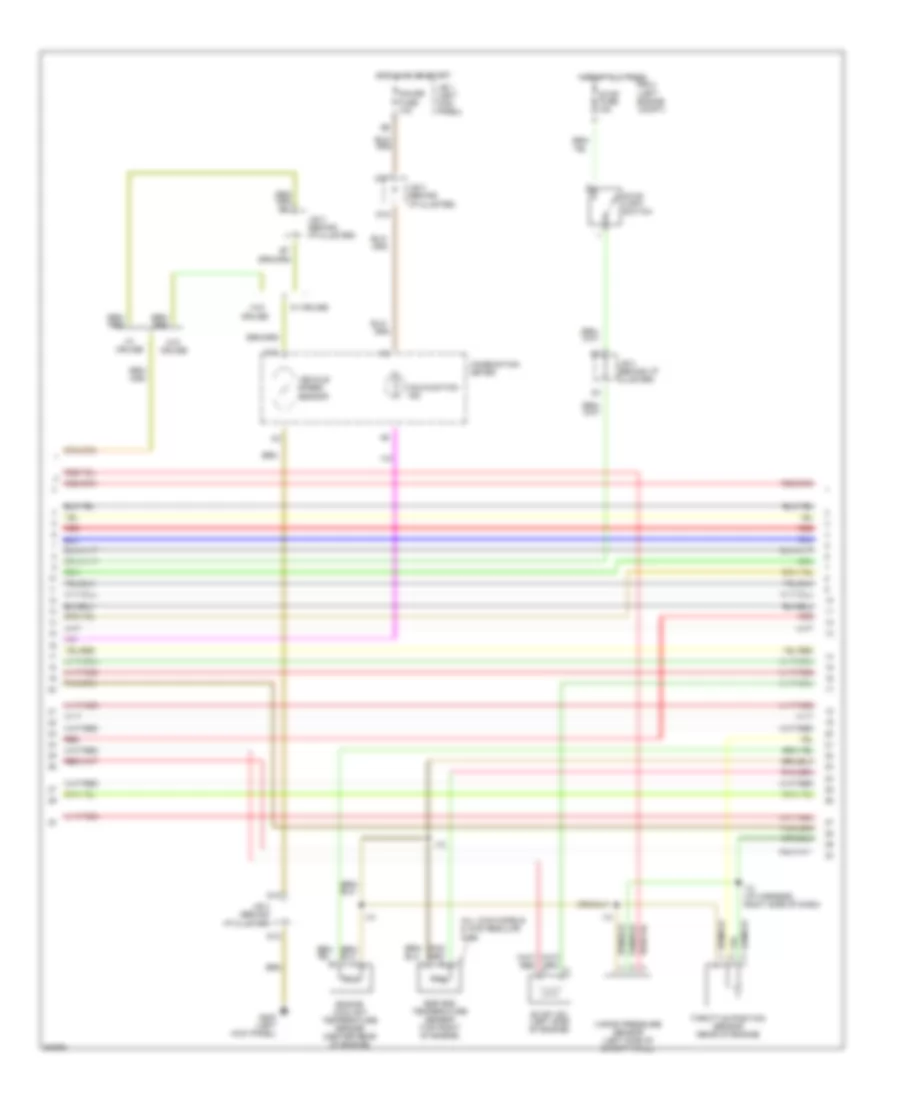
2.4L, Engine Performance Wiring Diagrams (2 of 2) for Toyota Tacoma 1997
List of elements for 2.4L, Engine Performance Wiring Diagrams (2 of 2) for Toyota Tacoma 1997:
- #10
- #20
- (a/t only)
- (at left kick panel)
- (center of i/p)
- (i/p harn, right side of dash)
- (left side of dash)
- (near throttle body)
- (right side of dash)
- A/t only
- C12
- C13
- Combination meter
- Conn e8
- Cruise control ecu (right kick panel)
- D j/c 4 (left side of i/p)
- D10
- D12
- D16
- D17
- D18
- D19
- Data link connector #3 (center of i/p)
- E01
- E02
- E03
- Egr
- Egr vsv (left side of engine)
- Engine control module (right side of i/p)
- Evap vsv (left side of engine)
- G113
- G201
- G202
- Gauge fuse 10a
- Heated oxygen sensor (bank 1 sensor 1) (bottom left of vehicle)
- Heated oxygen sensor (bank 1 sensor 2) (bottom left of vehicle)
- Hot at all times
- Hot in on or start
- Hot with tail relay energized
- Ht1
- Ht2
- I10
- Idle air control valve (top left side of engine)
- Igf
- Igt
- Intake air temperature sensor (right side of engine compt)
- J/b 1 (left kick panel)
- J/b 3
- J/b 3 (behind i/p cluster)
- J/b 3 (center of dash)
- J/b 3 (center of i/p)
- J/c 4 (left side of i/p)
- Malf. ind. lamp
- Nca
- Ne-
- O/d
- O/d cut relay (right side eng compt)
- O/d diode (right side of i/p) (a/t w/ cruise)
- O/d ind. lamp
- O/d main switch (a/t)
- O/d solenoid (on trans- mission)
- Obd fuse 10a
- Panel fuse 10a
- Prg
- R/b 2 (left engine compt)
- R/b 2 (left side of eng compt)
- Red
- Rsc
- Rso
- Stop light switch
- Stop stop stop stop stop fuse 15a
- Vehicle speed sensor
- W/ cruise
- W/o cruise
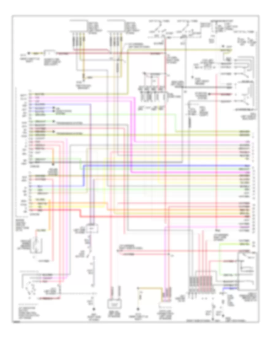
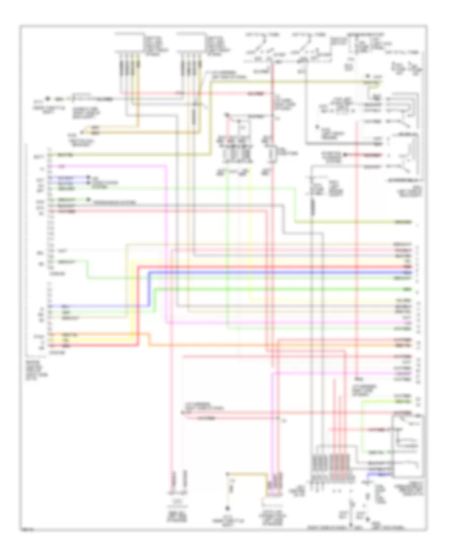
2.7L
2.7L, Engine Performance Wiring Diagrams, A/T (1 of 3) for Toyota Tacoma 1997
List of elements for 2.7L, Engine Performance Wiring Diagrams, A/T (1 of 3) for Toyota Tacoma 1997:
- (eng harn, left front fender)
- (i/p harness, left end of dash)
- (i/p harness, right side of dash)
- (i/p harness, right side of dash) i10
- (ignition coil bracket)
- (left engine compt)
- (near throttle body)
- (right side of dash)
- (top left of battery) j/c 1
- 4wd
- A/t indicator switch (park neutral position switch) (on trans)
- Acc
- Acc st1
- Aci
- Act
- Air conditioning system
- Am1 fuse 40a
- Batt
- Circuit opening relay (behind left side of i/p)
- Conn e5
- Conn e6
- Cruise control system
- Data link connector #1 (left side of engine)
- E12
- E13
- E14
- E15
- Efi fuse 15a
- Efi relay
- Egr vsv (left side of engine)
- Els
- Engine control module (right side of i/p)
- F15
- Fuel injectors
- Fuel pump (in fuel tank)
- G102 (left front fender)
- G113
- G113 (near throttle body)
- G125
- G201
- G201 (right side of dash)
- G202 (left kick panel)
- Hot at all times
- Hot in on or start
- I10
- I10 (i/p harn, right side of dash)
- Ig2
- Ign fuse 7.5a
- Ignition coil and ignitor 1 (left front of eng)
- Ignition coil and ignitor 2 (left front of eng)
- Ignition switch
- J/b 1 (left kick panel)
- J/b 3 (center of i/p)
- J/c 4 (left side of dash)
- Lock
- Ne-
- Noise filter (right side of eng compt)
- Nsw
- O/d main switch
- Od1
- Od2
- Oil-w
- Pnk
- Ptnk
- Pwr
- R/b 2
- R/b 2 (left side of eng compt)
- Red
- Sdl
- Sp1
- Sp2+
- Sp2-
- Sta
- Sta fuse 7.5a
- Start
- Starter relay
- Starting/ charging system
- Tfn
- Transmission system
- Vehicle speed sensor (on trans)
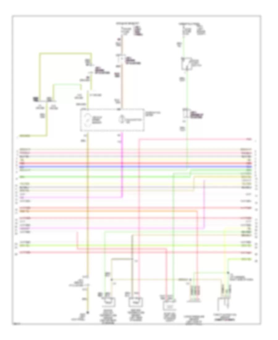
2.7L, Engine Performance Wiring Diagrams, A/T (2 of 3) for Toyota Tacoma 1997
List of elements for 2.7L, Engine Performance Wiring Diagrams, A/T (2 of 3) for Toyota Tacoma 1997:
- (behind i/p cluster) j/b 3
- (left side of dash) g202
- A/t oil temp ind.
- A12
- C10
- C11
- C12
- C13
- Combination meter
- D10
- D12
- D14
- D15
- D16
- D17
- D19
- Ect pwr ind.
- Egr gas temperature sensor (left rear of engine)
- Electronically controlled transmission pattern select switch
- Engine coolant temperature sensor (center rear of engine)
- Evap vsv (left side of engine compt)
- G200 (left kick panel)
- Gauge fuse 10a
- Hot at all times
- Hot in on or start
- Hot with tail relay energized
- I10
- I10 (i/p harness, right side of dash)
- J/b 1 (left kick panel)
- J/b 3 (behind i/p cluster)
- J/c 4 (left side of dash)
- Malfunction ind.
- O/d off ind.
- Panel fuse 10a
- Pnk
- R/b 2 (left engine compt)
- Red
- Speedo- meter
- Stop fuse 15a
- Stop light switch
- Throttle position sensor (throttle body)
- Vapor pressure sensor (left side of safety wall)
- W/ cruise
- W/ tach
- W/o cruise
- W/o tach
2.7L, Engine Performance Wiring Diagrams, A/T (3 of 3) for Toyota Tacoma 1997
List of elements for 2.7L, Engine Performance Wiring Diagrams, A/T (3 of 3) for Toyota Tacoma 1997:
- #10
- #20
- #30
- #40
- (i/p harn, right side of dash)
- (near throttle body)
- A/t oil temperature sensor (left side of trans)
- Camshaft position sensor (front of engine)
- Conn e7
- Conn e8
- Crankshaft position sensor (left side of engine)
- Cruise control system
- Data link connector #3 (center of i/p)
- E01
- E10
- Egr
- Electronic controlled transmission solenoid (on transmission)
- Engine control module (right side of i/p)
- Eo2
- Eo3
- Evp
- G113
- G113 (near throttle body)
- G201 (right side of dash)
- Heated oxygen sensor (bank 1 sensor 1) (exhaust system)
- Heated oxygen sensor (bank 1 sensor 2) (exhaust system)
- Hot at all times
- Ht1
- Ht2
- I10
- Idle air control valve (throttle body)
- Idlo
- Igf
- Igt1
- Igt2
- Instrument cluster system (tach)
- J/b 3 (behind i/p cluster)
- Knk
- Knock sensor (left front of engine)
- Mass air flow meter (air intake assembly)
- Nca
- Obd fuse 10a
- Oil
- Ox1
- Ox2
- Pnk
- R/b 2 (left engine compt)
- Red
- Rsc
- Rso
- Tac
- Te1
- Tha
- Thg
- Thw
- Transmission system
- Vcc
- Vta
2.7L, Engine Performance Wiring Diagrams, M/T (1 of 3) for Toyota Tacoma 1997
List of elements for 2.7L, Engine Performance Wiring Diagrams, M/T (1 of 3) for Toyota Tacoma 1997:
- (i/p harness, left end of dash)
- (i/p harness, right side of dash)
- (i/p harness, right side of dash) i10
- (ignition coil bracket)
- (left engine compt)
- (near throttle body)
- (right side of dash)
- (top left of battery) j/c 1
- 4wd
- Acc
- Acc st1
- Aci
- Act
- Air conditioning system
- Am1 fuse 40a
- Batt
- Circuit opening relay (behind left side of i/p)
- Conn e5
- Conn e6
- Data link connector #1 (left side of engine)
- E12
- E13
- E14
- E15
- Efi fuse 15a
- Efi relay
- Egr vsv (left side of engine)
- Engine control module (right side of i/p)
- F15
- Fuel injectors
- Fuel pump (in fuel tank)
- G102 (left front fender)
- G113
- G113 (near throttle body)
- G125
- G201
- G202 (left kick panel)
- Hot at all times
- Hot in on or start
- I10
- I10 (i/p harn, right side of dash)
- Ig2
- Ign fuse 7.5a
- Ignition coil and ignitor 1 (left front of eng)
- Ignition coil and ignitor 2 (left front of eng)
- Ignition switch
- J/b 1 (left kick panel)
- J/b 3 (center of i/p)
- Lock
- Ne-
- Noise filter (right side of eng compt)
- Ptnk
- R/b 2
- R/b 2 (left side of eng compt)
- Red
- Sdl
- Sp1
- Sta
- Sta fuse 7.5a
- Start
- Starter relay
- Starting/ charging system
- Transmission system
2.7L, Engine Performance Wiring Diagrams, M/T (2 of 3) for Toyota Tacoma 1997
List of elements for 2.7L, Engine Performance Wiring Diagrams, M/T (2 of 3) for Toyota Tacoma 1997:
- A5 a5 a5 a5 a5
- B5 b5 b5 b5 b5 b5
- C10
- Combination meter
- Cruise
- D10
- D12
- D17
- D19 d19 d19 d19 d19
- E6 e6 e6 e6 e6
- Egr gas temperature sensor (left rear of engine)
- Engine coolant temperature sensor (center rear of engine)
- Evap vsv (left side of engine compt)
- G200 (left kick panel)
- Gauge fuse 10a
- Hot at all times
- Hot in on or start
- I10
- I10 (i/p harness, right side of dash)
- J/b 1 j/b 1 j/b 1 j/b 1 j/b 1 (left (left (left (left (left kick kick kick kick kick panel) panel) panel) panel) panel)
- J/b 3 (behind i/p cluster)
- J/b 3 j/b 3 j/b 3 j/b 3 j/b 3 (behind (behind (behind (behind (behind i/p cluster) i/p cluster) i/p cluster) i/p cluster) i/p cluster)
- J/b 3 j/b 3 j/b 3 j/b 3 j/b 3 j/b 3 (behind i/p (behind i/p (behind i/p (behind i/p (behind i/p (behind i/p cluster) cluster) cluster) cluster) cluster) cluster)
- Malfunction ind.
- Pnk
- R/b 2 (left engine compt)
- Red
- Stop fuse 15a
- Stop light switch
- Throttle position sensor (throttle body) (throttle body) (throttle body) (throttle body) (throttle body) (throttle body)
- Vapor pressure sensor (left side of safety wall)
- Vehicle speed sensor
- W/ cruise
- W/o
- W/o cruise
2.7L, Engine Performance Wiring Diagrams, M/T (3 of 3) for Toyota Tacoma 1997
List of elements for 2.7L, Engine Performance Wiring Diagrams, M/T (3 of 3) for Toyota Tacoma 1997:
- #10
- #20
- #30
- #40
- (i/p harness, right side of dash)
- (near throttle body)
- Camshaft position sensor (front of engine)
- Conn e7
- Conn e8
- Crankshaft position sensor (left side of engine)
- Cruise control system
- Data link connector #3 (center of i/p)
- E01
- E10
- Egr
- Engine control module (right side of i/p)
- Eo2
- Eo3
- Evp
- G113
- G113 (near throttle body)
- G201 (right side of dash)
- Heated oxygen sensor (bank 1 sensor 1) (exhaust system)
- Heated oxygen sensor (bank 1 sensor 2) (exhaust system)
- Hot at all times
- Ht1
- Ht2
- I10
- Idle air control valve (throttle body)
- Idlo
- Igf
- Igt1
- Igt2
- Instrument cluster system (tach)
- J/b 3 (behind i/p cluster)
- Knk
- Knock sensor (left front of engine)
- Mass air flow meter (air intake assembly)
- Nca
- Obd fuse 10a
- Ox1
- Ox2
- Pnk
- R/b 2 (left engine compt)
- Red
- Rsc
- Rso
- Tac
- Te1
- Tha
- Thg
- Thw
- Tpc
- Vapor pressure sensor vsv (left side of safety wall)
- Vcc
- Vta
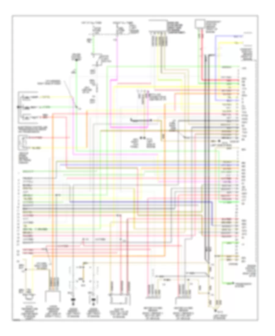
3.4L
3.4L, Engine Performance Wiring Diagrams, A/T (1 of 3) for Toyota Tacoma 1997
List of elements for 3.4L, Engine Performance Wiring Diagrams, A/T (1 of 3) for Toyota Tacoma 1997:
- (floor a/t)
- (i/p harn, right side of dash)
- (left engine compt)
- (left front fender)
- (left side of engine)
- (right side of dash)
- (right side of engine compartment)
- (top left of battery) j/c 1
- 4wd
- Ac1
- Acc
- Acc st1
- Act
- Air conditioning
- Am1 fuse 40a
- Batt
- Circuit opening relay (behind left side of i/p)
- Conn e5
- Conn e6
- Cruise control system
- Data link connector #1 (left side of engine)
- E12
- E13
- E14
- E15
- E3 (eng harn, rear of left front fender)
- Efi fuse 15a
- Efi relay
- Egr
- Egr vsv (left side of engine)
- Engine control module (right side of i/p)
- Evp1
- F15
- Floor a/t
- Fuel injectors
- Fuel pump (in fuel tank)
- G102
- G112
- G112 (left side of engine)
- G201
- G202 (left kick panel)
- Hot at all times
- Hot in on or start
- I10
- I10 (i/p harn, right side of dash)
- Idlo
- Ig2
- Ign fuse 7.5a
- Igniter
- Ignition coil no. 1 (top right side of engine)
- Ignition coil no. 2 (top right side of engine)
- Ignition coil no. 3 (top right side of engine)
- Ignition switch
- Instrument cluster system (tachometer)
- J/b 1 (left kick panel)
- J/b 3 (center of i/p)
- Lock
- Od1
- Od2
- Oil -w
- Pnk
- Pwr
- R/b 2
- R/b 2 (left side of eng compt)
- Red
- Sdl
- Sp1
- Sta fuse 7.5a
- Start
- Starter relay
- Starting
- System
- Te1
- Tfn
- Tpc
- Transmission system
- Vapor pressure sensor vsv (left side of safety wall)
3.4L, Engine Performance Wiring Diagrams, A/T (2 of 3) for Toyota Tacoma 1997
List of elements for 3.4L, Engine Performance Wiring Diagrams, A/T (2 of 3) for Toyota Tacoma 1997:
- (all 2wd models & 4wd reg cab)
- (at left kick panel)
- (center of i/p)
- (column a/t)
- (floor a/t)
- (left side
- (w/ tach) (w/o tach)
- A/t indicator switch (on transmission)
- A/t oil temp ind.
- A12
- B4 (column a/t)
- B5 (column a/t)
- C10
- C11
- C13
- Cig fuse 15a
- Column a/t
- Combination meter
- Cruise
- D ind.
- D n
- D1 a5
- D10
- D12
- D14
- D15 d19
- D16
- D17
- Ect pwr
- Egr gas temperature sensor (top center of engine)
- Electronically controlled transmission pattern select switch
- Engine coolant temperature sensor (center rear of engine)
- Evap vsv (left side of engine)
- F19
- F20
- Floor a/t
- G200
- Gauge fuse 10a
- Hot in acc or on
- Hot in on or start
- I10
- I10 (i/p harn, right side of dash)
- Ind.
- J/b 1 (left kick panel)
- J/b 3
- J/b 3 (behind i/p cluster)
- J/b 3 (center of i/p)
- J/c 4
- J/c 4 (left side of dash)
- J/c 4 (left side of i/p)
- J/c 8 (right side of dash)
- L ind.
- Malf. ind. lamp
- N ind.
- Norm
- O/d ind lamp
- O/d main switch
- Of i/p)
- Pnk
- Pwr
- R ind.
- Throttle position sensor (rear of engine)
- Vehicle speed sensor
- W/ column a/t
- W/ cruise
- W/ floor a/t
- W/o
- W/o cruise
- P ind.
3.4L, Engine Performance Wiring Diagrams, A/T (3 of 3) for Toyota Tacoma 1997
List of elements for 3.4L, Engine Performance Wiring Diagrams, A/T (3 of 3) for Toyota Tacoma 1997:
- #10
- #20
- #30
- #40
- #50
- #60
- (center of i/p)
- (i/p harn, right side dash)
- (i/p harn, right side of dash)
- (i/p harness, right side of dash)
- (left front of engine)
- (left side of eng)
- A/t oil temperature sensor (center rear of engine compt)
- Camshaft position sensor (front of engine)
- Conn e7
- Conn e8
- Crankshaft position sensor (front of engine)
- Cruise control system
- E01
- E02
- E03
- E10
- Electronic controlled transmission solenoid (on transmission)
- Engine control module (right side of i/p)
- G110
- G112
- G112 (left side of engine)
- G201 (right kick panel)
- Heated oxygen sensor (bank 1 sensor 1) (bottom left of vehicle)
- Heated oxygen sensor (bank 1 sensor 2) (bottom left of vehicle)
- Hot at all times
- Ht1
- Ht2
- I10
- Idle air control valve (top left side of engine)
- Igf
- Igt1
- Igt2
- Igt3
- J/b 3
- Knk1
- Knk2
- Knock sensor 1 (left front of engine)
- Knock sensor 2 (left front of engine)
- Mass air mass air flow meter flow meter (right side (right side of engine of engine compartment) compartment)
- Nca
- Ne-
- Nsw
- Obd fuse 10a
- Oil
- Ox1
- Ox2
- Ptnk
- R/b 2 (left engine compt)
- Red
- Rsc
- Rso
- Sp2+
- Sp2-
- Sta
- Stop fuse 15a
- Stop light switch
- Tha
- Thg
- Thw
- Transmission system
- Vapor pressure sensor (left side of safety wall)
- Vcc
- Vehicle speed sensor (on trans- mission)
- Vta
3.4L, Engine Performance Wiring Diagrams, M/T (1 of 3) for Toyota Tacoma 1997
List of elements for 3.4L, Engine Performance Wiring Diagrams, M/T (1 of 3) for Toyota Tacoma 1997:
- (i/p harn, right side of dash)
- (i/p harness, right side of dash)
- (i/p harness, right side of dash) i10
- (left engine compt)
- (left side of engine)
- (right side of dash)
- (right side of engine compartment)
- (top left of battery) j/c 1
- 4wd
- Acc
- Acc st1
- Aci
- Act
- Air conditioning system
- Am1 fuse 40a
- Batt
- Circuit opening relay (behind left side of i/p)
- Conn e5
- Conn e6
- Data link connector #1 (left side of engine)
- E03
- E12
- E13
- E14
- E15
- Efi fuse 15a
- Efi relay
- Egr vsv (left side of engine)
- Engine control module (right side of i/p)
- F15
- Fuel injectors
- Fuel pump (in fuel tank)
- G102 (left front fender)
- G110 (left front of engine)
- G112
- G201
- G202 (left kick panel)
- Hot at all times
- Hot in on or start
- Ht1
- Ht2
- I10
- Ig2
- Ign fuse 7.5a
- Igniter
- Ignition coil no. 1 (top right side of engine)
- Ignition coil no. 2 (top right side of engine)
- Ignition coil no. 3 (top right side of engine)
- Ignition switch
- Instrument cluster system (tachometer)
- J/b 1 (left kick panel)
- J/b 3 (center of i/p)
- Lock
- Ne-
- Ptnk
- R/b 2
- R/b 2 (left side of eng compt)
- Red
- Sdl
- Sp1
- Sta
- Sta fuse 7.5a
- Start
- Starter relay
- Starting/ charging system
- Transmission system
3.4L, Engine Performance Wiring Diagrams, M/T (2 of 3) for Toyota Tacoma 1997
List of elements for 3.4L, Engine Performance Wiring Diagrams, M/T (2 of 3) for Toyota Tacoma 1997:
- (all 2wd models & 4wd regular cab)
- C10
- Combination meter
- Cruise
- D10
- D12
- D17
- D19
- Egr gas temperature sensor (top right of engine)
- Engine coolant temperature sensor (center rear of engine)
- Evap vsv (left side of engine)
- G200 (left kick panel)
- Gauge fuse 10a
- Hot at all times
- Hot in on or start
- I10
- I10 (i/p harness, right side of dash)
- J/b 1 (left kick panel)
- J/b 3 (behind i/p cluster)
- Malfunction ind.
- R/b 2 (left engine compt)
- Red
- Stop fuse 15a
- Stop light switch
- Throttle position sensor (rear of engine)
- Vapor pressure sensor (left side of safety wall)
- Vehicle speed sensor
- W/ cruise
- W/o
- W/o cruise
3.4L, Engine Performance Wiring Diagrams, M/T (3 of 3) for Toyota Tacoma 1997
List of elements for 3.4L, Engine Performance Wiring Diagrams, M/T (3 of 3) for Toyota Tacoma 1997:
- #10
- #20
- #30
- #40
- #50
- #60
- (i/p harn, right side of dash)
- (i/p harness, right side of dash)
- (left front of engine)
- (left side of engine)
- Camshaft position sensor (front of engine)
- Conn e7
- Conn e8
- Crankshaft position sensor (front of engine)
- Cruise control system
- Data link connector #3 (center of i/p)
- E01
- E10
- Egr
- Engine control module (right side of i/p)
- Evp1
- G110
- G112
- G112 (left side of engine)
- G201 (right side of dash)
- Heated oxygen sensor (bank 1 sensor 1) (bottom left of vehicle)
- Heated oxygen sensor (bank 1 sensor 2) (bottom left of vehicle)
- Hot at all times
- I10
- Idle air control valve (top left side of engine)
- Idlo
- Igf
- Igt1
- Igt2
- Igt3
- J/b 3 (behind i/p cluster)
- Knk1
- Knk2
- Knock sensor 1 (left front of engine)
- Knock sensor 2 (left front of engine)
- Mass air flow meter (right side of engine compartment)
- Nca
- Obd fuse 10a
- Ox1
- Ox2
- R/b 2 (left engine compt)
- Red
- Rsc
- Rso
- Te1
- Tha
- Thg
- Thw
- Tpc
- Vapor pressure sensor vsv (left side of engine)
- Vcc
- Vta
EXTERIOR LIGHTS
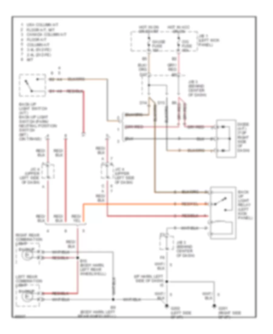
Back-up Lamps Wiring Diagram for Toyota Tacoma 1997
List of elements for Back-up Lamps Wiring Diagram for Toyota Tacoma 1997:
- (body harn, left rear wheelwell)
- (i/p harn, left side of dash) i5
- 2.4l (2vz-fe)
- 3.4l (5vz-fe)
- B10 (body harn, left rear wheelwell)
- Back up light relay (left kick panel)
- Back-up light switch (a/t) back-up light switch (park/ neutral position switch (m/t) (on trans)
- Backup
- Canada column a/t
- Cig fuse 15a
- Column a/t
- D13
- D14
- D17
- Diode (a/t) (top right side of dash)
- Floor a/t
- Floor a/t, m/t
- G201 (right side of i/p)
- G202 (left side of i/p)
- Gauge fuse 10a
- Hot in acc or on
- Hot in on or start
- J/b 1 (left kick panel)
- J/b 3 (behind center of dash)
- J/c 4 (upper left side of dash)
- Left rear combination light
- M/t
- Right rear combination light
- Usa column a/t
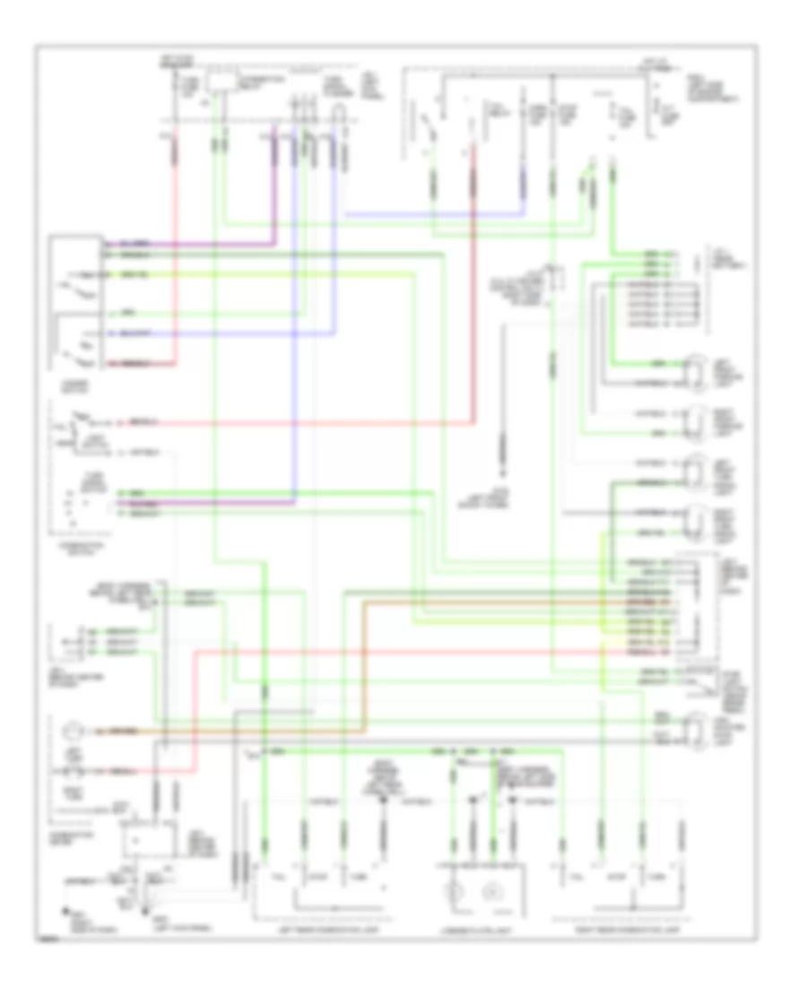
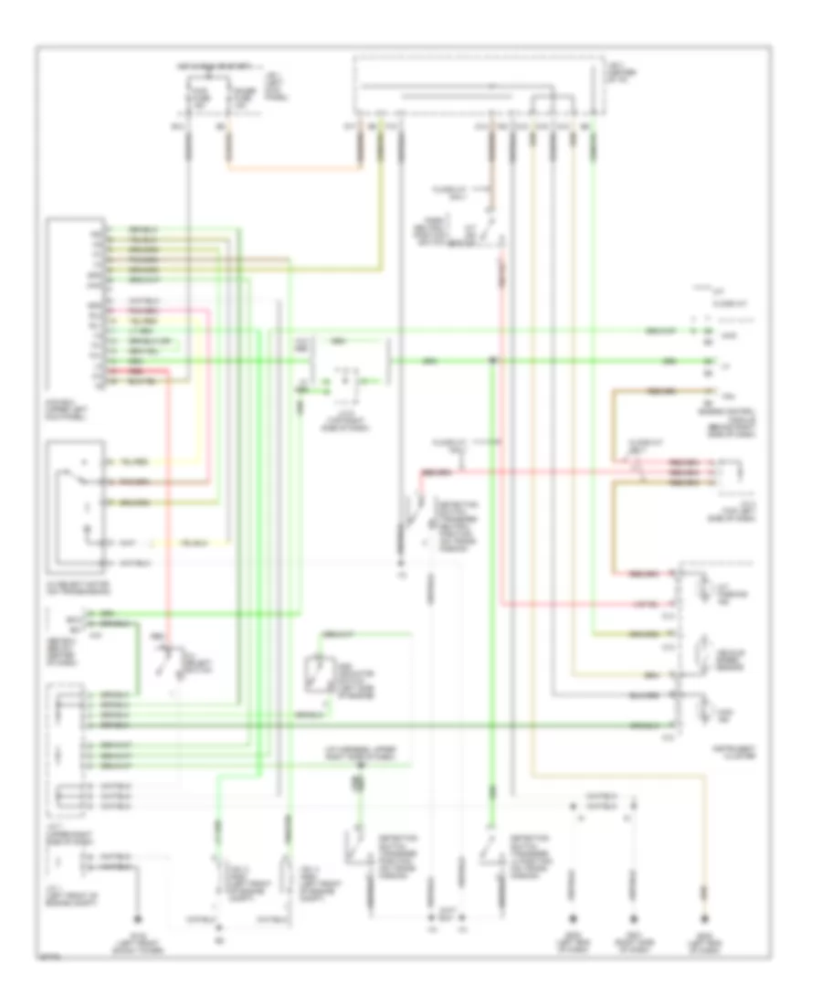
Exterior Lamps Wiring Diagram for Toyota Tacoma 1997
List of elements for Exterior Lamps Wiring Diagram for Toyota Tacoma 1997:
- (body harness, above left rear wheelwell)
- (body harness, behind left rear wheelwell) b10
- (left kick panel)
- A11
- A12
- A15
- A16
- Alt fuse 80a
- B10
- B11
- B11 (body harness, behind left side of rear bumper)
- C11
- C13
- Combination meter
- Combination switch
- F11
- F14
- F19
- F20
- G102 (left front shock tower)
- G200
- G201 (right side of dash)
- Hazard switch
- Head
- High mounted stop light
- Horn fuse 15a
- Hot at all times
- Hot in on or start
- Integration relay
- J/b 1 (left kick panel)
- J/b 3 (behind center of dash)
- J/c 1 (near battery)
- J/c 8 (3.4l w/ cruise control only) (right side of dash)
- Left front parking light
- Left front turn signal light
- Left rear combination lamp
- Left turn
- License plate light
- Light switch
- Off
- R/b 2 (left side of engine compartment)
- Right front parking light
- Right front turn signal light
- Right rear combination lamp
- Right turn
- Stop
- Stop fuse 15a
- Stop light switch (above brake pedal)
- Tail
- Tail fuse 10a
- Tail relay
- Turn
- Turn fuse 10a
- Turn signal flasher
- Turn signal switch
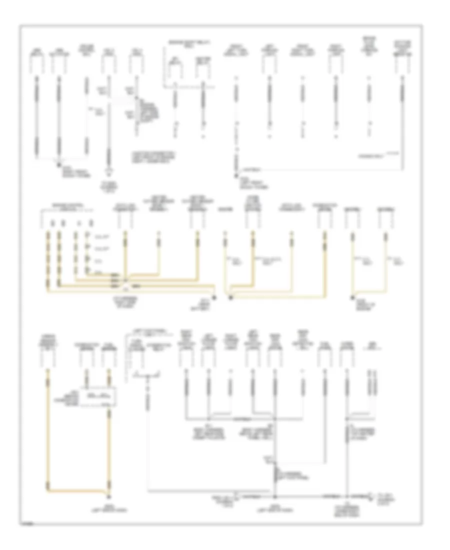
GROUND DISTRIBUTION
Ground Distribution Wiring Diagram (1 of 2) for Toyota Tacoma 1997
List of elements for Ground Distribution Wiring Diagram (1 of 2) for Toyota Tacoma 1997:
- (engine compt relay) r/b 2
- (i/p harness, right side of dash)
- (left kick panel) j/b 1
- 2.4l
- 2.4l & 2.7l only
- 2.7l
- 2.7l only
- 3.4l a/t
- 3.4l m/t
- 3.4l only
- A11
- A24
- Abs actuator
- Abs ecu
- Abs relay
- Airbag sensor assembly e1
- B11 (body harness, left rear side under tailgate)
- B16
- B9 (body harness, above left rear wheel well)
- Brake fluid level warning sw
- Canada only
- Combination meter
- Cruise control ecu
- D10
- D11
- D12
- D13
- D14
- D24
- D25
- D26
- D33
- D34
- Data link connector 1
- Data link connector 3
- Daytime running light resistor
- E01
- E02
- E03
- E2 (engine harness, left side of engine compt)
- Efi relay
- Engine control module
- From vsv 4 a (diagram 1 of 2)
- Front left turn signal light
- Front right turn signal light
- Fuel pump
- Fuel sender
- G102 (left front shock tower)
- G103 (right front shock tower)
- G111 (near battery)
- G125 (front of engine)
- G202) (left end of dash)
- Heated oxygen sensor (bank 1 sensor 1)
- Heated oxygen sensor (bank 1 sensor 2)
- Heater relay
- I10
- I12 (i/p harness, upper right end of dash)
- I6 (i/p harness, top center of dash)
- Igniter
- Igniter 1
- Igniter 2
- Integration relay
- J/b 3 (behind combination meter)
- Junction connector 1 (left front of engine compt, under r/b 2)
- Left license plate light
- Left parking light
- Left rear com- bination light
- Noise filter (ignition system)
- Rear diff lock detection sw
- Rear diff lock motor
- Right license plate light
- Right parking light
- Right rear com- bination light
- To g200 (diagram 1 of 2)
- To j/b 3 (diagram 2 of 2)
- Turn signal flasher
- Vsv 2 (add)
- Vsv 4 (add)
- Wiper motor
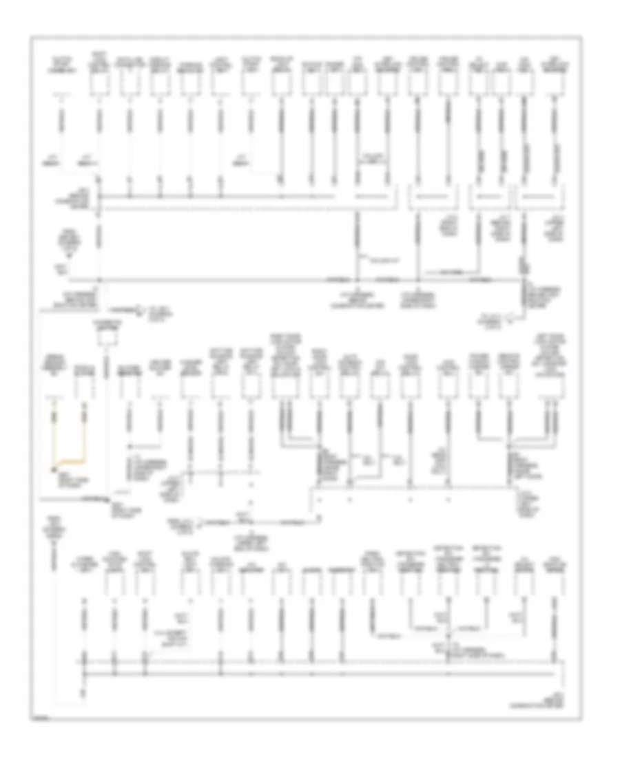
Ground Distribution Wiring Diagram (2 of 2) for Toyota Tacoma 1997
List of elements for Ground Distribution Wiring Diagram (2 of 2) for Toyota Tacoma 1997:
- (3.4l except column shift a/t)
- (a/t only)
- (canada)
- (floor
- (floor a/t) a
- (w/ 4wd)
- (w/ 4wd) c
- (w/ rear diff lock only)
- 2-4 select motor
- 2-4 select sw
- 2.4l only
- 3.4l only
- 4wd control ecu
- 4wd ecu
- A/c amplifier
- A/c sw
- A/t only
- A/t)
- A10
- A13
- Airbag sensor assembly e2
- Auto antenna control relay
- B3 (body harness, inside left door)
- B8 (body harness, inside right door)
- Back-up light relay
- Blower resistor
- Buckle sw
- C11
- C12
- C13
- Cigarette lighter
- Circuit opening relay
- Clock
- Clutch start cancel sw
- Clutch start sw
- Column a/t
- Com- bination meter
- Cruise control ecu
- Cruise control sw
- Data link connector
- Daytime running light relay (main)
- Daytime running light relay no 4
- Detection sw (transfer l4 position)
- Detection sw (transfer neutral position)
- Detection sw (transfer position)
- Dimmer sw
- Door lock control relay
- F10
- F11
- F12
- F13
- F14
- F15
- F16
- F17
- F18
- F19
- F20
- From abs ecu (diagram 1 of 2)
- From j/b 3 (diagram 2 of 2)
- From j/c 4 (diagram 2 of 2)
- G201 (right side of dash)
- Glove box light sw
- Heater blower sw
- High mounted stop light
- I10 (i/p harness, right side of dash)
- I11 (i/p harness, upper right side of dash)
- I4 (i/p harness, upper left end of dash)
- I5 (i/p harness, behind com- bination meter)
- I5 (i/p harness, behind combination meter)
- I8 (i/p harness, upper right side of dash)
- J/b 3 (behind combination meter)
- J/c 2 (upper left side of dash)
- J/c 3 (upper left side of dash)
- J/c 4 (upper left side of dash)
- J/c 7 (behind right side of dash)
- J/c 8 (right end of dash)
- Key interlock solenoid
- Left door lock motor & door unlock detection sw, door key lock unlock sw
- Light control sw
- M/t only
- O/d cut relay
- O/d main sw
- Park/ neutral position sw
- Parking brake sw
- Power window master sw
- Radio & player
- Remote control mirror sw
- Rheostat
- Right door lock control sw
- Right door lock motor & door unlock detection sw, door key lock & unlock sw
- Shift lock control relay
- Shift lock control sw
- To j/b 3 (diagram 2 of 2)
- To j/c 3 (diagram 2 of 2)
- Unlock warning sw
- Washer level sensor
- Wiper & washer sw
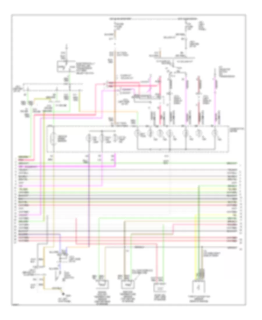
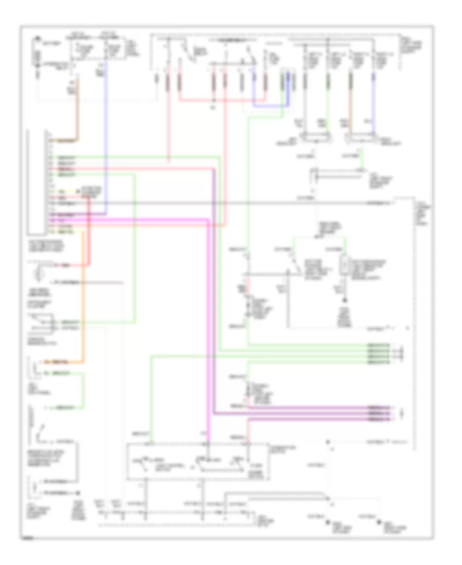
HEADLIGHTS
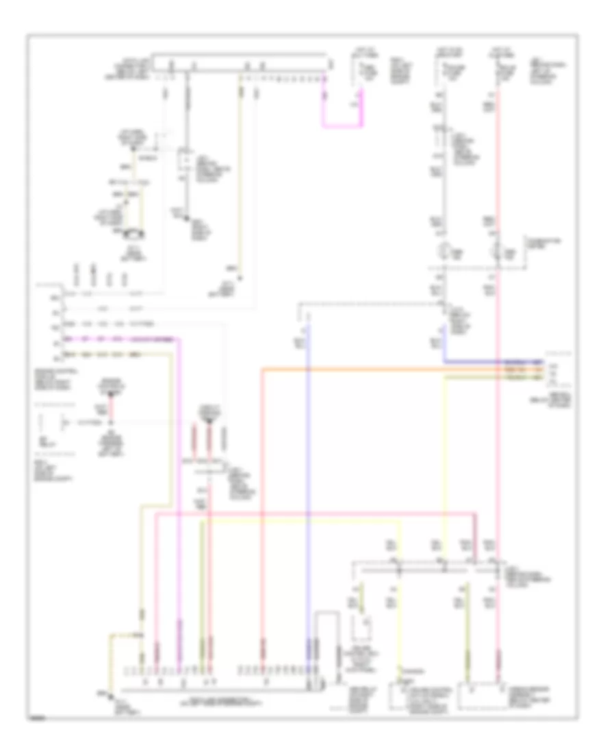
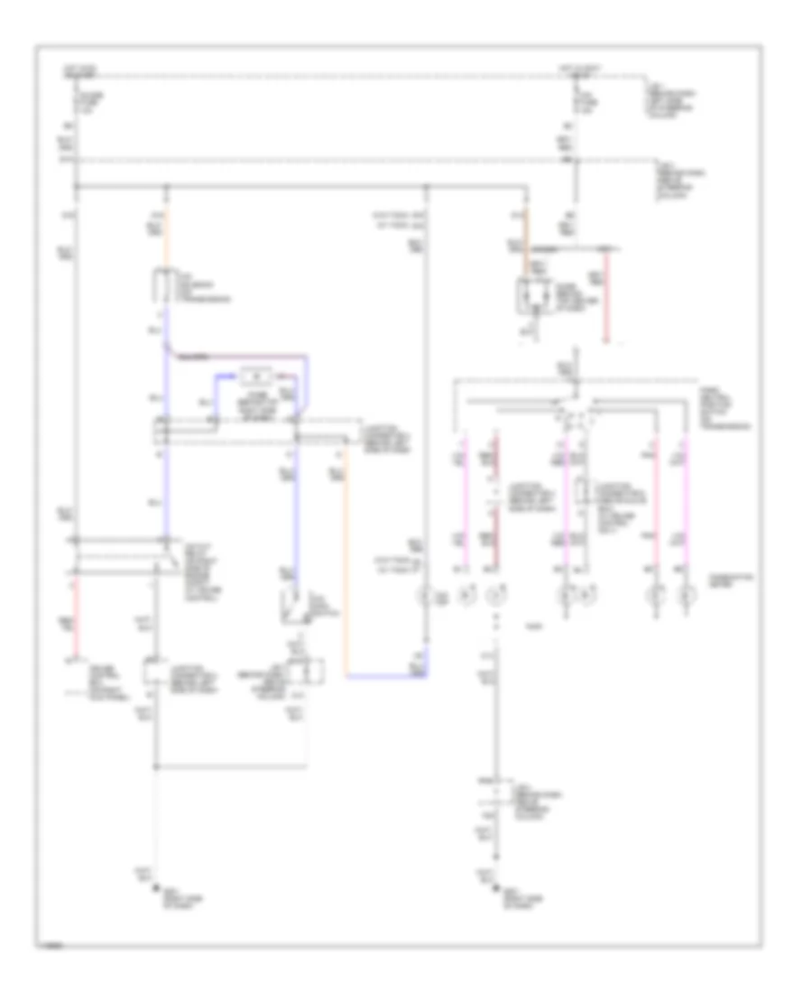
Headlight Wiring Diagram, with DRL for Toyota Tacoma 1997
List of elements for Headlight Wiring Diagram, with DRL for Toyota Tacoma 1997:
- (eng harn, left front fender) e2
- Battery
- Brake fluid level warning switch (on brake fluid reservoir)
- Combination switch
- Daytime running light relay (main) (center of dash)
- Daytime running light relay 4 (right side of dash)
- Daytime running light resistor (left front side of engine compt)
- Dimmer relay
- Dimmer switch
- Diode 1 (drl) (top left side of dash)
- Diode 2 (drl) (top left center of dash)
- Drl fuse 7.5a
- Ecu-b fuse 15a
- F19
- F20
- Flash
- G102 (left front shock tower)
- G201 (right side of dash)
- G202 (left end of dash)
- Gauge fuse 10a
- Head
- Head relay
- High
- High beam indicator
- Hot at all times
- Hot in on or start
- Instrument cluster
- Integration relay
- J/b 1 (left kick panel)
- J/b 3 (center of i/p)
- J/c 1 (left front of engine compt)
- J/c 3 (upper left side of dash)
- Left headlight
- Left hi head fuse 10a
- Left lo head fuse 10a
- Light control switch
- Off
- Parking brake switch
- R/b 2 (left side of engine compt)
- Red
- Right headlight
- Right hi head fuse 10a
- Right lo head fuse 10a
- Starting/ charging system
- Tail
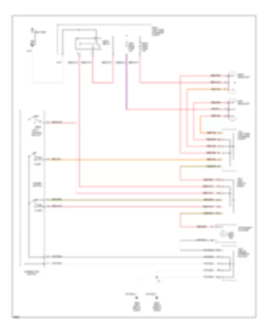
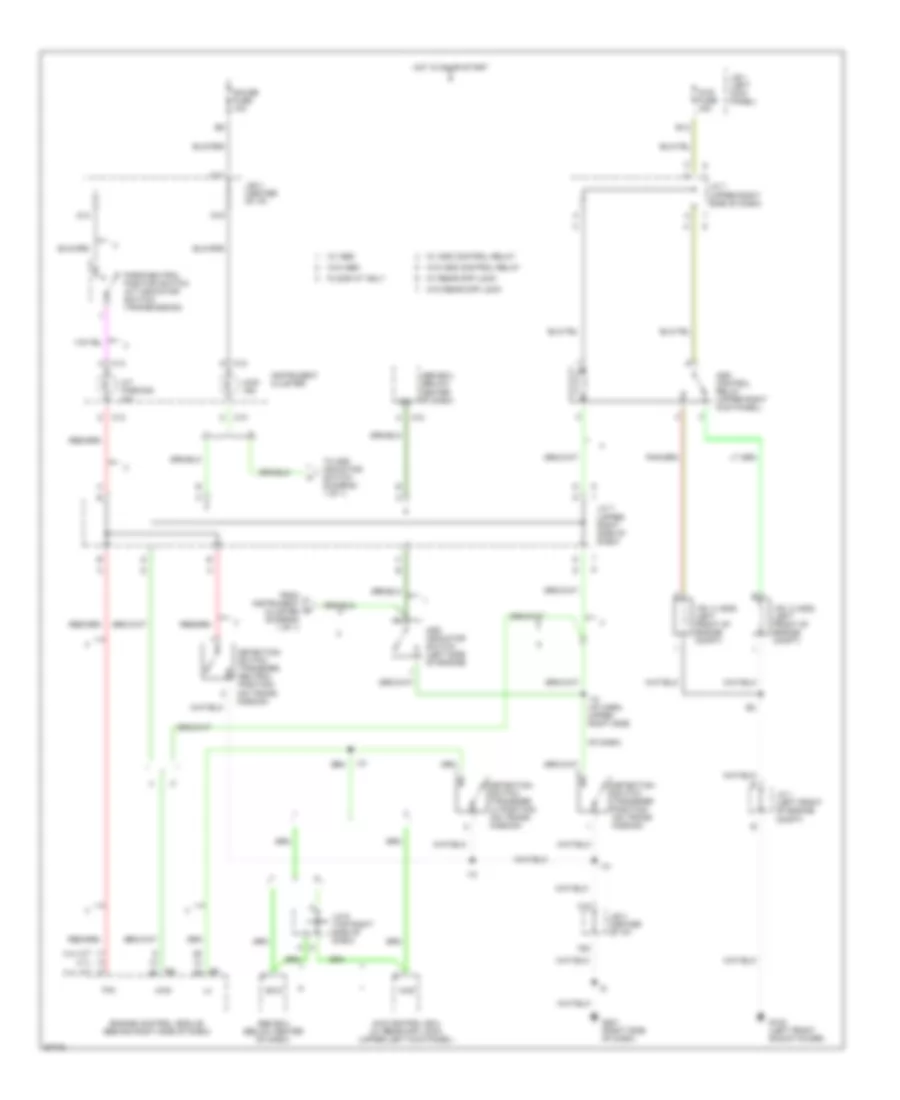
Headlight Wiring Diagram, without DRL for Toyota Tacoma 1997
List of elements for Headlight Wiring Diagram, without DRL for Toyota Tacoma 1997:
- A14
- Battery
- C17
- Combination switch
- Dimmer switch
- F13
- F19
- F20
- Flash
- G201 (right side of dash)
- G202 (left end of dash)
- Head
- Head relay
- High
- High beam ind
- Instrument cluster
- J/b 1 (left side of dash)
- J/b 3 (above steering column)
- J/c 1 (left side of engine compt)
- Left head fuse 10a
- Left headlight
- Light control switch
- Off
- R/b 2 (left side of engine compt)
- Right head fuse 10a
- Right headlight
- Tail
HORN
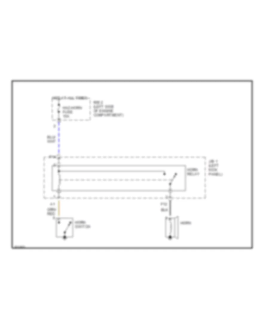
Horn Wiring Diagram for Toyota Tacoma 1997
List of elements for Horn Wiring Diagram for Toyota Tacoma 1997:
- F12
- F14
- Haz-horn fuse 15a
- Horn
- Horn relay
- Horn switch
- Hot at all times
- J/b 1 (left kick panel)
- R/b 2 (left side of engine compartment)
INSTRUMENT CLUSTER
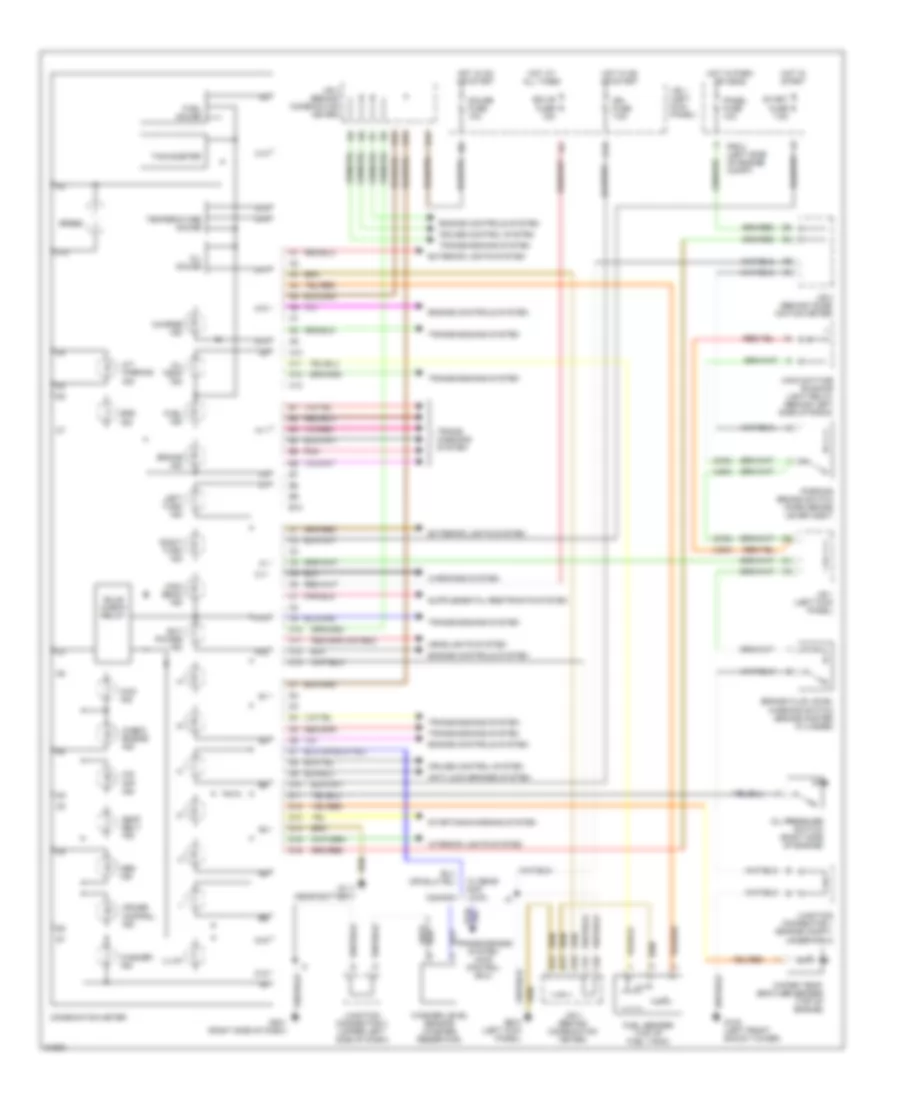
Instrument Cluster Wiring Diagram for Toyota Tacoma 1997
List of elements for Instrument Cluster Wiring Diagram for Toyota Tacoma 1997:
- (can)
- (usa)
- 4wd ind
- A/t parking ind
- A10
- A11
- A12
- A13
- Abs ind
- Anti-lock brakes system
- B10
- Brake fluid level warning switch (brake master cylinder)
- Brake ind
- Bulb check relay
- C10
- C11
- C12
- C13
- Canada
- Charge ind
- Check engine ind
- Combination meter
- Cruise control ind
- Cruise control system
- D10
- D11
- D12
- D13
- D14
- D15
- D16
- D17
- D19
- Ect power ind
- Ecu-b fuse 15a
- Engine controls system
- Exterior lights system
- F19
- F20
- Fuel gauge
- Fuel ind
- Fuel sender (top of fuel tank)
- G102 (left front shock tower)
- G111 (near battery)
- G200 (left kick panel)
- G201 (right side of dash)
- Gauge fuse 10a
- Headlights system
- High beam ind
- Hot at all times
- Hot in on or start
- Hot in park or head
- Hot in start
- Ign fuse 7.5a
- Illum
- Interior lights system
- J/b 1 (left kick panel)
- J/b 3 (behind comb- ination meter)
- J/b 3 (behind combination meter)
- Junction connector 1 (engine compt, under r/b 2)
- Junction connector 3 (upper left side of dash)
- Left turn ind
- Main daytime running light relay (behind left side of radio)
- O/d off ind
- Oil gauge
- Oil pressure switch (right side of engine)
- Oil temp ind
- Panel fuse 10a
- Parking brake switch (park brake lever assy)
- Pnk
- R/b 2 (left side of engine compt)
- Right turn ind
- Seat belt ind
- Speed
- Srs ind
- Start fuse 7.5a
- Starting/charging system
- Tachometer
- Temperature gauge
- Trans- missions system
- Transmissions system
- Transmissions system (4wd control ecu)
- W/ rear diff lock
- Warnings system
- Washer ind
- Washer level sensor (washer reservoir)
- Water temp- erature sender (top of engine)
INTERIOR LIGHTS
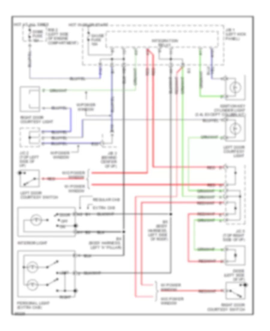
Courtesy Lamps Wiring Diagram for Toyota Tacoma 1997
List of elements for Courtesy Lamps Wiring Diagram for Toyota Tacoma 1997:
- A12
- B4 (body harness, left "a" pillar)
- B5 (body harness, left side of roof)
- Diode (left side of i/p)
- Dome fuse 15a
- Door
- E18
- E22
- Extra cab
- F10
- Gauge fuse 10a
- Hot at all times
- Hot in on or start
- Ignition key cylinder light (3.4l except column a/t)
- Integration relay
- Interior light
- J/b 1 (left kick panel)
- J/b 3 (behind center of i/p)
- J/c 2 (top left side of i/p)
- J/c 5 (top right side of i/p)
- Left
- Left door courtesy light
- Left door courtesy switch
- Off
- Personal light (extra cab)
- R/b 2 (left side of engine compartment)
- Red
- Regular cab
- Right
- Right door courtesy light
- Right door courtesy switch
- W/ power window
- W/o power window
- W/power window
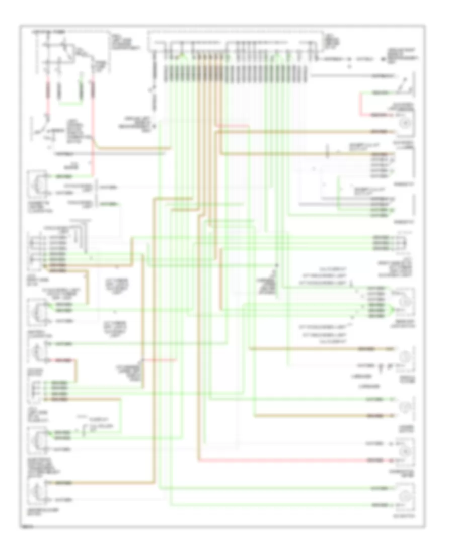
Instrument Illumination Wiring Diagram for Toyota Tacoma 1997
List of elements for Instrument Illumination Wiring Diagram for Toyota Tacoma 1997:
- (around left edge of reinforcement) g202
- (around right edge of reinforcement) g201
- 2 speaker
- 3.4l column a/t
- 3.4l engine
- 3.4l floor a/t
- 4 speaker
- A/c switch
- A10
- Ashtray illumination
- C14
- C15
- C16
- C17
- C18
- C19
- C20
- C21
- C22
- Cigarette lighter illumination
- Combination meter
- Electronic controlled transmission pattern select switch
- Except 2.4l m/t & 2.7l m/t
- F12
- F17
- F20
- Floor a/t
- Glove box light
- Glove box light switch
- Hazard switch
- Head
- Heater blower switch
- Hot at all times
- I5 (i/p harness, upper left side of dash)
- I6 (i/p harness, upper center of dash)
- J/b 3 (behind center of i/p)
- J/c 4 (left side of i/p) (floor a/t)
- J/c 7 (right side of i/p) (m/t w/rear diff lock & glove box light)
- J/c 8 (right side of i/p)
- Light control switch (part of combination switch
- M/t w/glove box light
- M/t w/o glove box light
- M/t w/rear diff. lock & glove box light
- O/d main switch
- Off
- Panel fuse 10a
- R/b 2 (left side of engine compartment)
- Radio & player
- Rear diff. lock switch
- Rheostat
- Tail
- Tail relay
- W/ glove box light, w/o m/t w/rear diff. lock
- W/glove box light
- W/o glove box light
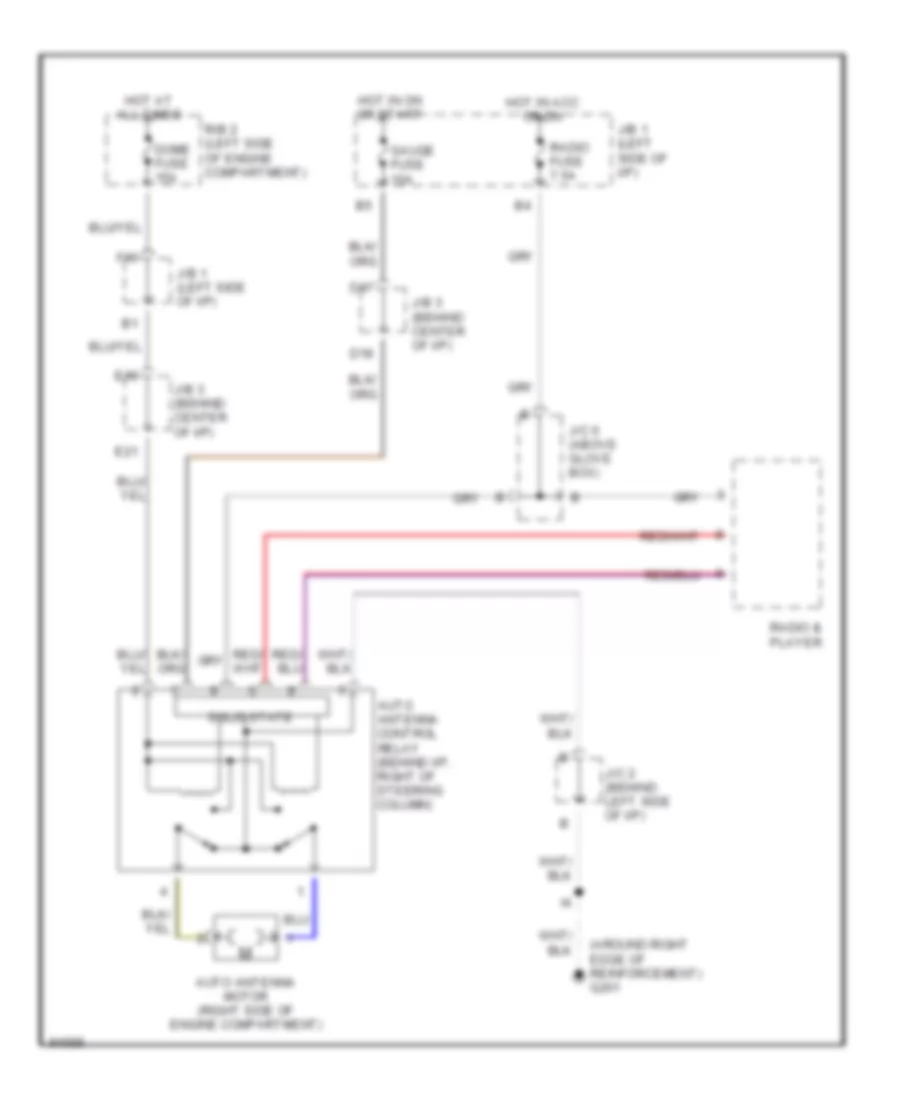
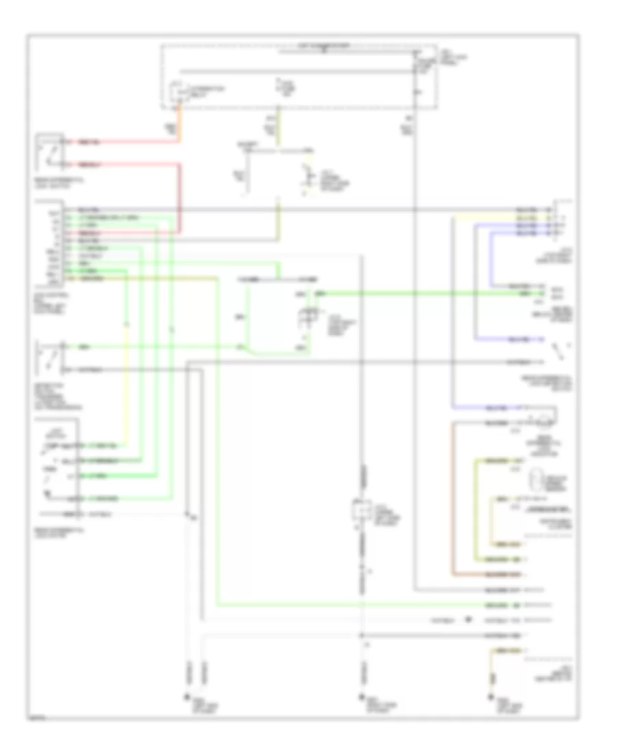
POWER ANTENNA
Power Antenna Wiring Diagram for Toyota Tacoma 1997
List of elements for Power Antenna Wiring Diagram for Toyota Tacoma 1997:
- (around right edge of reinforcement) g201
- Auto antenna control relay (behind i/p, right of steering column)
- Auto antenna motor (right side of engine compartment)
- D17
- D18
- Dome fuse 15a
- E18
- E21
- F10
- Gauge fuse 10a
- Hot at all times
- Hot in acc or on
- Hot in on or start
- J/b 1 (left side of i/p)
- J/b 1 (left side of i/p)
- J/b 3 (behind center of i/p)
- J/c 2 (behind left side of i/p)
- J/c 6 (above glove box)
- R/b 2 (left side of engine compartment)
- Radio & player
- Radio fuse 7.5a
- Solid state
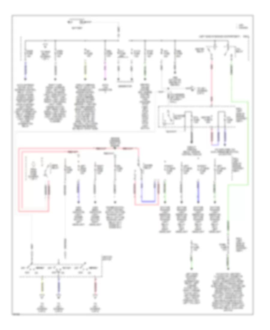
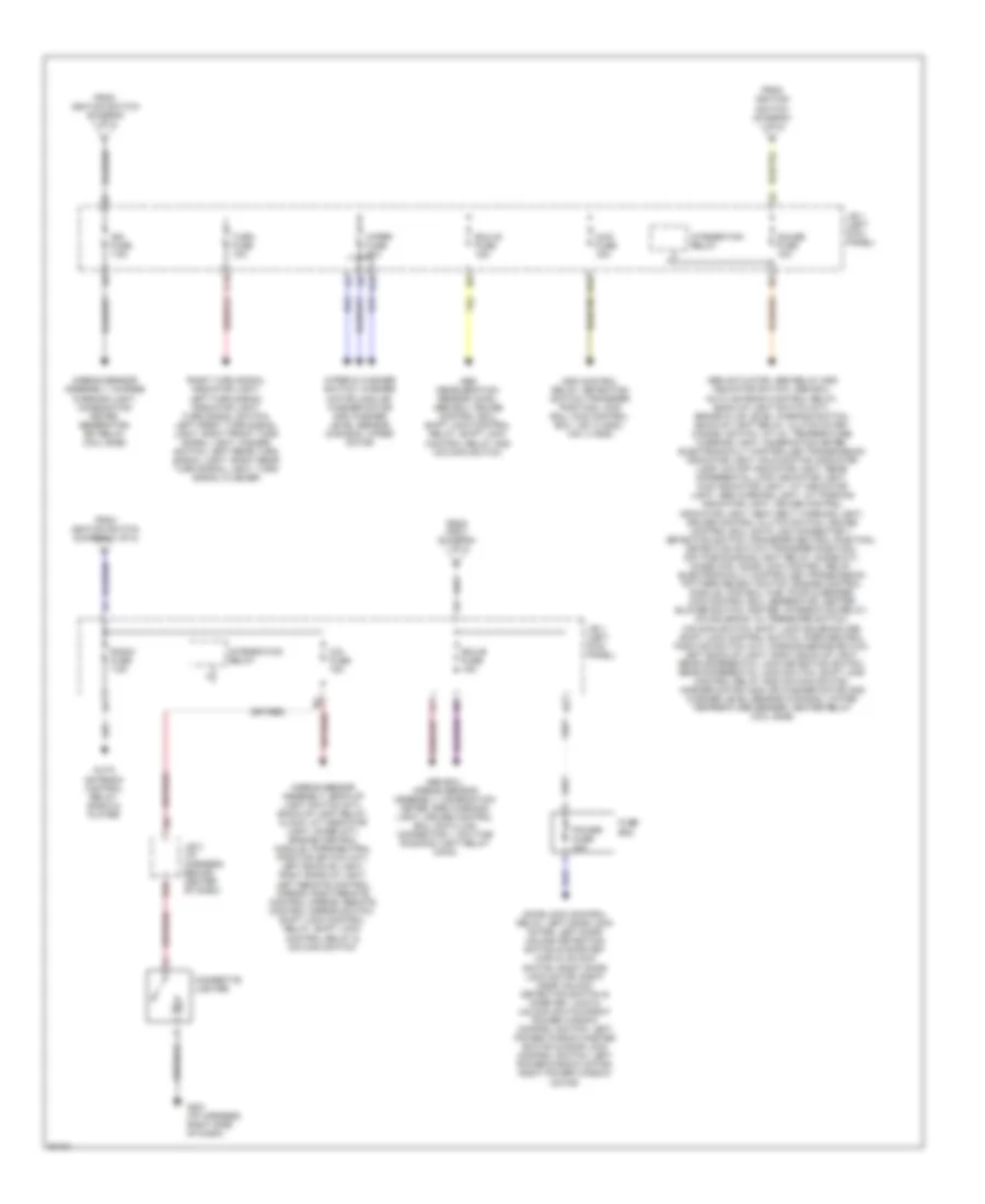
POWER DISTRIBUTION
Power Distribution Wiring Diagram (1 of 2) for Toyota Tacoma 1997
List of elements for Power Distribution Wiring Diagram (1 of 2) for Toyota Tacoma 1997:
- (engine harness, front of engine) e1
- (left side of engine compartment)
- A.c fuse 10a
- A/c amplifier, a/c dual pressure switch, a/c switch
- A/c switch, ashtray illumination, cigarette lighter illumination, clock, combination meter, seat belt warning light, electronically controlled transmission pattern select swtch, engine control module, glove box light, glove box light switch, hazard switch, heater blower switch, radio & player, rheostat, right taillight, shift lock control relay & o/d main switch
- Abs actuator, abs relay, abs ecu
- Abs ecu, cruise control ecu, engine control module, high mounted stop light, left stop light, right stop light, stop light switch
- Abs fuse 60a
- Acc
- Alt fuse 80a
- Alt-s fuse 7.5a
- Am1 fuse 40a
- Am2 fuse 30a
- Auto antenna motor, auto antenna control relay, clock, diode (power window), right door courtesy switch, left door courtesy light, right door courtesy light, integration relay, interior light, personal light, radio & player, integration relay
- Battery
- Canada
- Circuit opening relay, data link connector 1, engine control module, fuel pump & sender, heated oxygen sensor (bank 1 sensor 1), heated oxygen sensor (bank 1 sensor 2), idle air control valve, mass air flow meter, vsv (a/c idle-up), vsv (egr), vsv (evap), vsv (fpu), vsv (vapor pressure sensor), efi relay (point side)
- Circuit opening relay, engine control module
- Data link connector
- Daytime running light resistor, daytime running light relay no 4, left headlight
- Daytime running light resistor, daytime running light relay no 4, right headlight
- Dimmer relay
- Dimmer switch, light control switch, daytime running light
- Dome fuse 15a
- Drl fuse 7.5a
- Efi fuse 15a
- From dome fuse (diagram 1 of 1)
- Generator
- Head relay
- Heater fuse 40a
- Heater relay
- High beam indicator light, dimmer switch, left headlight
- High beam indicator light, dimmer switch, right headlight
- Horn fuse 15a
- I1 (i/p harness, left bottom of safety wall)
- Ignition switch
- Left door courtesy switch, integration relay, left license plate light, right license plate light, left parking light, right parking light, left taillight
- Left head fuse 10a
- Left hi head fuse 10a
- Left lo head fuse 10a
- Obd fuse 10a
- Off
- Panel fuse 10a
- R/b 2
- R/b 2 (left side of engine compart- ment)
- Red
- Relay, daytime running light relay no 4, diode no 1, diode no 2
- Right head fuse 10a
- Right hi head fuse 10a
- Right lo head fuse 10a
- Right turn signal interior light, left turn signal interior light, horn switch, left front turn signal light, right front turn signal light, horn, hazard switch, left rear turn signal light, right rear turn signal light, horn relay, turn signal flasher,
- Sta fuse 7.5a
- Start
- Starter relay
- Stop fuse 15a
- Tail fuse 10a
- Tail relay
- To head relay (diagram 1 of 1)
- To j/b 1 (diagram 2 of 2)
- To j/b 1, (diagram 2 of 2)
- Usa
Power Distribution Wiring Diagram (2 of 2) for Toyota Tacoma 1997
List of elements for Power Distribution Wiring Diagram (2 of 2) for Toyota Tacoma 1997:
- 4wd fuse 15a
- Abs actuator, abs relay,add indicator switch, abs ecu, auto antenna control relay, back-up light switch (m/t), brake fluid level warning switch, back-up light relay, clutch start cancel switch, a/t oil temperature warning light, combination meter, electronically controlled transmission indicator light, malfunction indicator lamp, o/d off indicator light, rear differential lock indicator light, 4wd indicator light, a/t indicator light, abs warning light, a/t parking indicator light, cruise control indicator light, seat belt warning light, cruise control clutch switch, cruise control ecu, data link connector 1, detection switch (transfer neutral position), detection switch (transfer position), daytime running light relay, diode (a/t), diode (o/d), door lock control relay, electronically controlled transmission pattern select switch, engine control module, 4wd ecu, fuel pump & sender, 4wd control ecu, generator, heater blower switch, igniter, integration relay, o/d solenoid, oil pressure switch, o/d main switch, shift lock solenoid and shift lock control switch, park/neutral position switch (a/t), parking brake switch, left back-up light, right back-up light, rear differential lock detection switch, rear differential lock switch, shift lock control relay and o/d main switch, washer motor (usa) or washer motor and washer level sensor (canada), water temperature sender, heater relay (coil side)
- Abs deceleration sensor (4wd), abs ecu, cruise control ecu, shift lock control relay, shift lock control relay and o/d main switch
- Abs ecu, airbag sensor assembly, combination meter, srs warning light, cruise control ecu, data link connector 1, daytime running light relay (main)
- Add control relay, detection switch (transfer position), 4wd ecu, 4wd control ecu, vsv 2 (add), vsv 4 (add)
- Airbag sensor assembly, back-up light switch (m/t), back-up light relay, clock, a/t indicator light, diode (a/t), engine control module, park/neutral position switch (a/t), left back-up light, right back-up light, left remote control mirror, right remote control mirror, remote control mirror switch, shift lock control relay, shift lock control relay & o/d main switch
- Airbag sensor assembly, charge warning light, combination meter, generator, efi relay (coil side)
- Auto antenna control relay, radio & player
- B10
- B12
- C14
- Cig fuse 15a
- Cigarette lighter
- Door lock control relay, left door lock motor, left door unlock detection switch & door key lock & unlock switch, right door lock motor, right door unlock detection switch & door key lock & unlock switch,right power window control switch, left power window master switch & door lock control switch, left power window motor, right power window motor
- Ecu-b fuse 15a
- Ecu-ig fuse 15a
- From ignition switch (diagram 1 of 2)
- From r/b 2 (diagram 1 of 2)
- Fuse box
- G201 (i/p harness, right side of dash)
- Gauge fuse 10a
- Ign fuse 7.5a
- Integration relay
- J/b 1 (left kick panel)
- J/b 3 (i/p harness, behind center of dash)
- Power fuse 30a
- Radio fuse 7.5a
- Right turn signal indicator light, left turn signal indicator light, turn signal switch, left front turn signal light, right front turn signal light, hazard switch, left rear turn signal light, right rear turn signal light, turn signal flasher
- Turn fuse 10a
- Wiper & washer switch, washer motor (usa) or washer motor and washer level sensor (canada), wiper motor
- Wiper fuse 20a
POWER DOOR LOCKS
Power Door Lock Wiring Diagram for Toyota Tacoma 1997
List of elements for Power Door Lock Wiring Diagram for Toyota Tacoma 1997:
- (body harn, in left door) b2
- (body harn, in right door) b8
- B3 (body harn, in left door)
- B6 (body harn, in right door)
- B7 (body harn, in right door)
- Door lock control relay (left side of i/p)
- F13
- F20
- Fuse box (left kick panel)
- G200 (left kick panel)
- G203 (right kick panel)
- Hot at all times
- I12
- Interior lights system (integration relay)
- J/b 3 (behind center of i/p)
- Junction connector j2 (left side of i/p)
- Junction connector j5 (right side of i/p)
- Left door courtesy switch
- Left door key lock/unlock switch
- Left door lock control switch (power window master switch)
- Left door lock motor/ unlock detection switch
- Lock
- Lock timer
- Power fuse 30a
- Red
- Right door courtesy switch
- Right door key lock/unlock switch
- Right door lock control switch
- Right door lock motor/ unlock detection switch
- Solid state
- Unlock
- Unlock timer
- Unlock warning switch
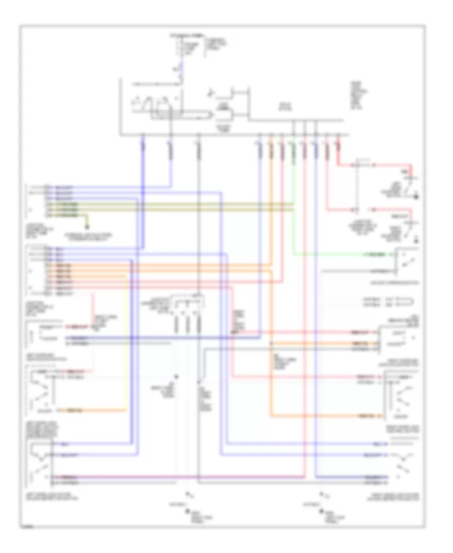
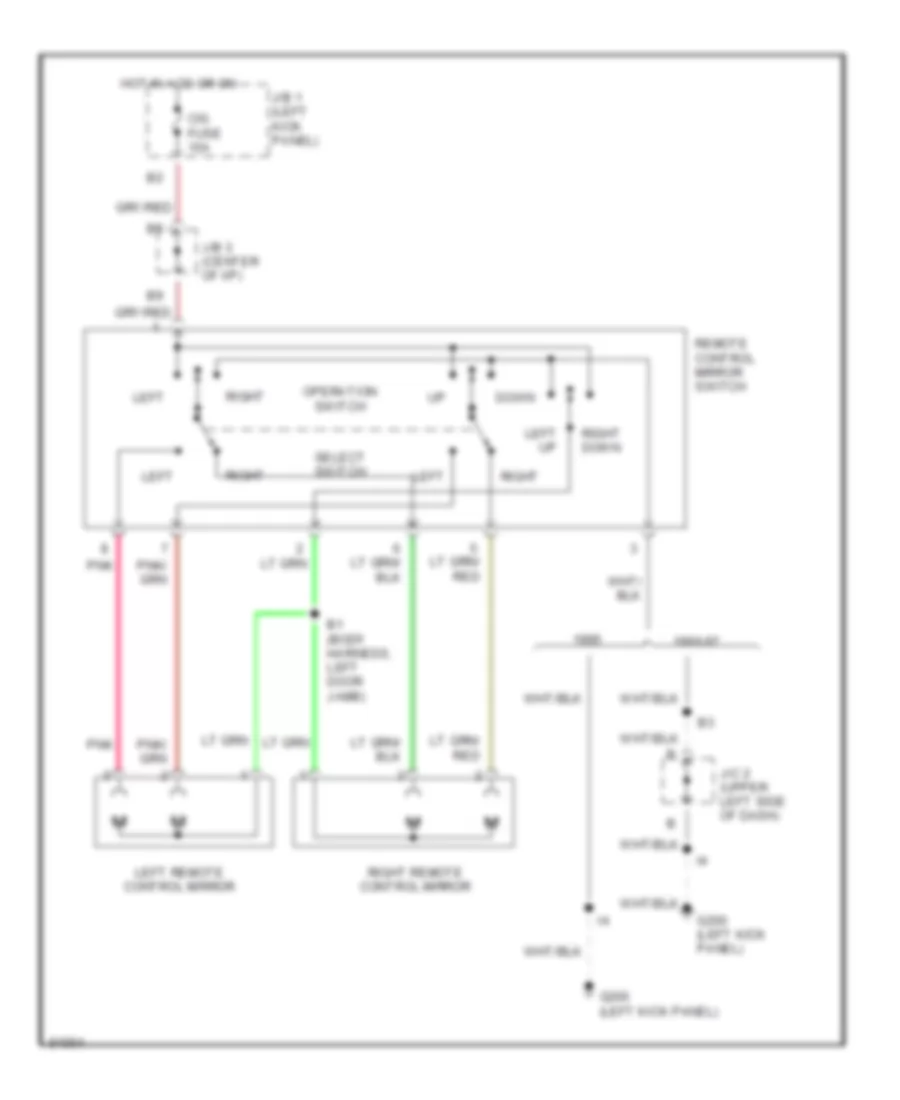
POWER MIRRORS
Power Mirror Wiring Diagram for Toyota Tacoma 1997
List of elements for Power Mirror Wiring Diagram for Toyota Tacoma 1997:
- 1996-97
- B1 (body harness, left door jamb)
- Cig fuse 15a
- Down
- G200 (left kick panel)
- Hot in acc or on
- J/b 1 (left kick panel)
- J/b 3 (center of i/p)
- J/c 2 (upper left side of dash)
- Left
- Left remote control mirror
- Left up
- Operation switch
- Pnk
- Remote control mirror switch
- Right
- Right down
- Right remote control mirror
- Select switch
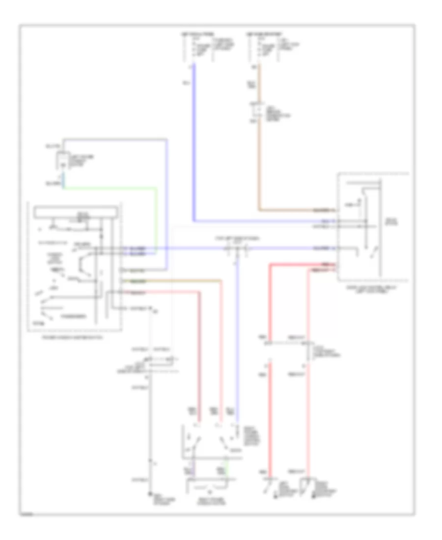
POWER WINDOWS
Power Window Wiring Diagram for Toyota Tacoma 1997
List of elements for Power Window Wiring Diagram for Toyota Tacoma 1997:
- (top left side of dash) j/c 2
- D17
- D20
- Door lock control relay (left kick panel)
- Down
- Driver's
- Fuse box (left side of dash)
- G201 (right side of dash)
- Gauge fuse 10a
- Hot at all times
- Hot in on or start
- J/b 1 (left kick panel)
- J/b 3 (behind combination meter)
- J/c 2 (top left side of dash)
- J/c 5 (top right side of dash)
- Left door courtesy switch
- Left power window motor
- Lock
- Normal
- Passenger's
- Power fuse 30a
- Power window master switch
- Red
- Right door courtesy switch
- Right power window control switch
- Right power window motor
- Solid state
- Window lock switch
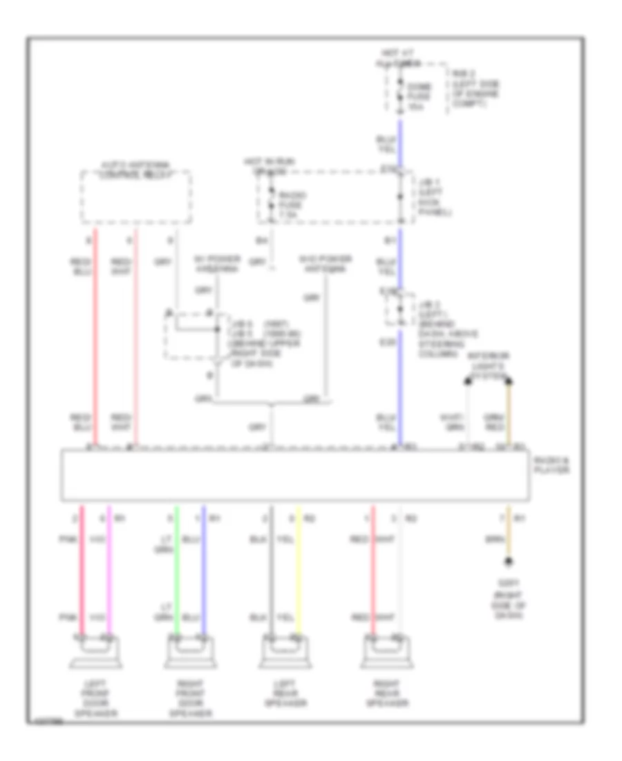
RADIO
Radio Wiring Diagrams for Toyota Tacoma 1997
List of elements for Radio Wiring Diagrams for Toyota Tacoma 1997:
- (1997) (1995-96)
- (right side of dash)
- Auto antenna control relay
- Dome fuse 15a
- E18
- E20
- F10
- G201
- Hot at all times
- Hot in run or acc
- Interior lights system
- J/b 1 (left kick panel)
- J/b 3 (left) (behind dash, above steering column)
- J/b 6 j/b 5 (behind upper right side of dash)
- Left front door speaker
- Left rear speaker
- Pnk
- R/b 2 (left side of engine compt)
- Radio & player
- Radio fuse 7.5a
- Red
- Right front door speaker
- Right rear speaker
- W/ power antenna
- W/o power antenna
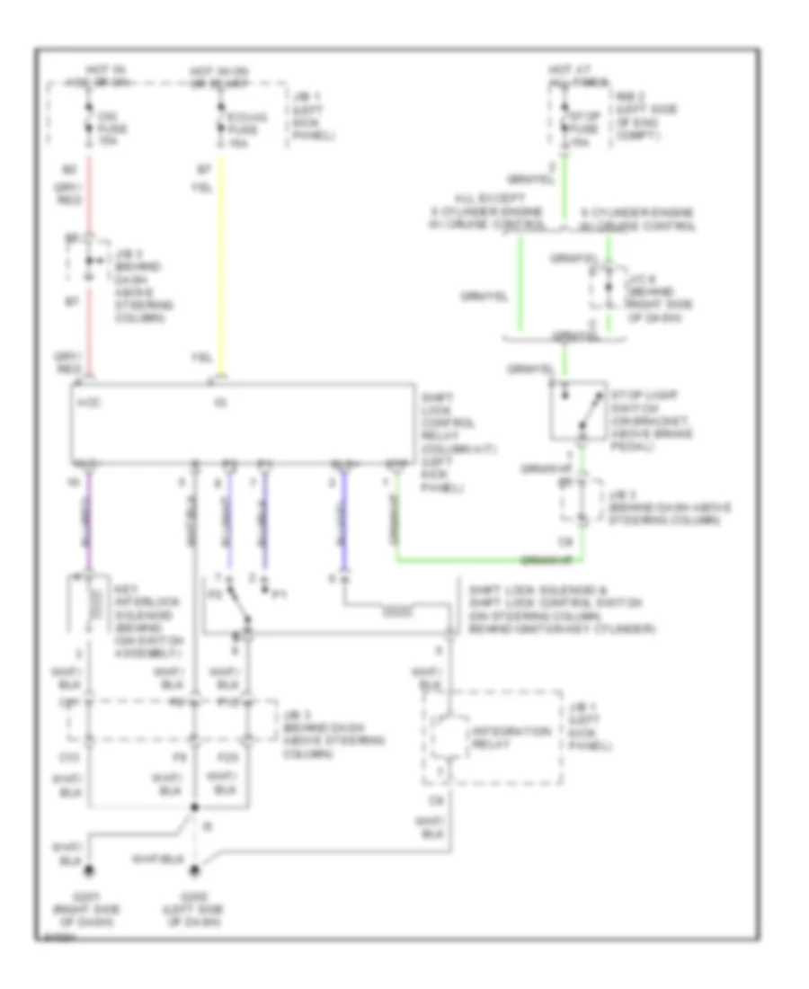
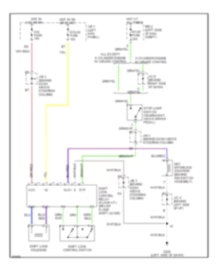
SHIFT INTERLOCKS
Shift Interlock Wiring Diagram, with Column Shift for Toyota Tacoma 1997
List of elements for Shift Interlock Wiring Diagram, with Column Shift for Toyota Tacoma 1997:
- 6 cylinder engine w/ cruise control
- Acc
- All except 6 cylinder engine w/ cruise control
- C11
- C13
- Cig fuse 15a
- E e
- Ecu-ig fuse 15a
- F12
- F20
- G201 (right side of dash)
- G202 (left side of dash)
- Hot at all times
- Hot in acc or on
- Hot in on or start
- Integration relay
- J/b 1 (left kick panel)
- J/b 3 (behind dash above steering column)
- J/c 8 (behind right side of dash)
- Key interlock solenoid (behind ign switch assembly)
- Kls+
- R/b 2 (left side of eng compt)
- Shift lock control relay (column a/t) (left kick panel)
- Shift lock solenoid & shift lock control switch (on steering column, behind ignition key cylinder)
- Sls+
- Stop fuse 15a
- Stop light switch (on bracket, above brake pedal)
- Stp
Shift Interlock Wiring Diagram, with Floor Shift for Toyota Tacoma 1997
List of elements for Shift Interlock Wiring Diagram, with Floor Shift for Toyota Tacoma 1997:
- 6 cylinder engine w/ cruise control
- Acc
- All except 6 cylinder engine w/ cruise control
- Cig fuse 15a
- Ecu-ig fuse 15a
- G202 (left side of dash)
- Hot at all times
- Hot in acc or on
- Hot in on or start
- J/b 1 (left kick panel)
- J/b 3 (behind dash above steering column)
- J/c 4 (behind left side of i/p)
- J/c 8 (behind right side of dash)
- Key interlock solenoid (behind ign switch assembly)
- Kls+
- R/b 2 (left side of eng compt)
- Shift lock control relay (floor a/t) (below floor shift lever)
- Shift lock control switch
- Shift lock solenoid
- Sls+
- Sls-
- Stop fuse 15a
- Stop light switch (on bracket, above brake pedal)
- Stp
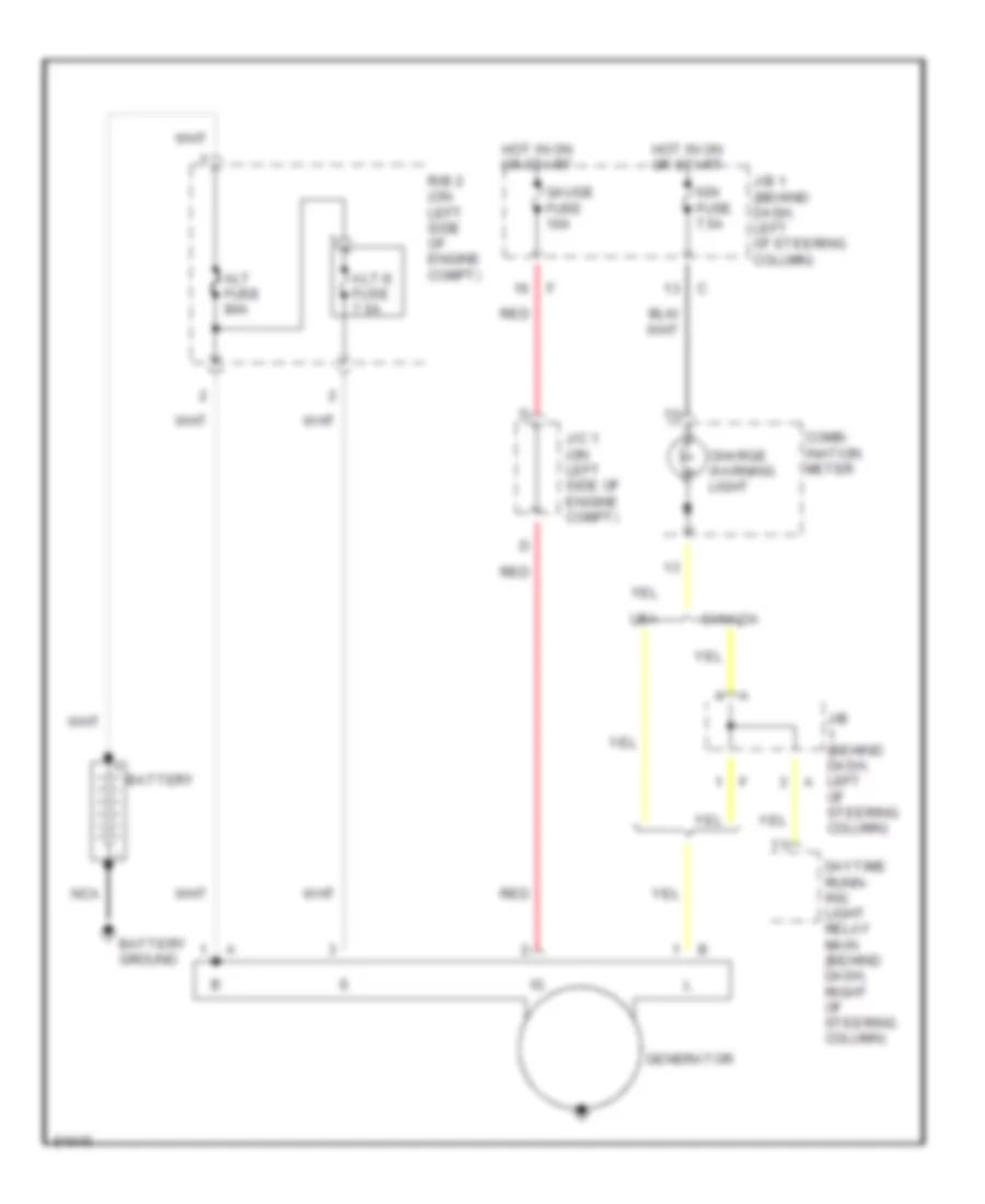
STARTING/CHARGING
Charging Wiring Diagram for Toyota Tacoma 1997
List of elements for Charging Wiring Diagram for Toyota Tacoma 1997:
- Alt fuse 80a
- Alt-s fuse 7.5a
- Battery
- Battery ground
- Canada
- Charge warning light
- Comb- ination meter
- Daytime runn- ing light relay main (behind dash, right of steering column)
- Gauge fuse 10a
- Generator
- Hot in on or start
- Ign fuse 7.5a
- J/b (behind dash, left of steering column)
- J/b 1 (behind dash, left of steering column)
- J/c 1 (on left side of engine compt)
- Nca
- R/b 2 (on left side of engine compt)
- Red
- Usa
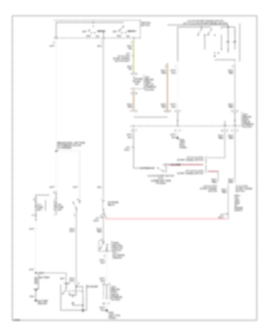
Starting Wiring Diagram for Toyota Tacoma 1997
List of elements for Starting Wiring Diagram for Toyota Tacoma 1997:
- (behind dash, left side of steering column, i/p harness) i1
- A/t only
- Acc
- Alt fuse 80a
- Am1 fuse 40a
- Battery
- Battery ground
- Clutch start cancel switch (m/t w/ clutch start cancel switch)
- Clutch start switch (m/t) (under left side of dash)
- G200 (left kick panel)
- Gauge fuse 10a
- Ignition switch
- J/b 1 (behind dash, left of steering column)
- J/b 3 (behind dash, above steering column)
- M/t only
- M/t w/ clutch start cancel switch
- M/t w/ clutch start cancel switch only
- M/t w/o clutch start cancel switch
- Nca
- Off
- P/ n
- Park/ neutral position switch (a/t) (on trans- mission)
- R/b 2 (on left side of engine compt)
- Start
- Starter
- Starter relay
- W/ clutch start cancel switch
- W/o clutch start cancel switch
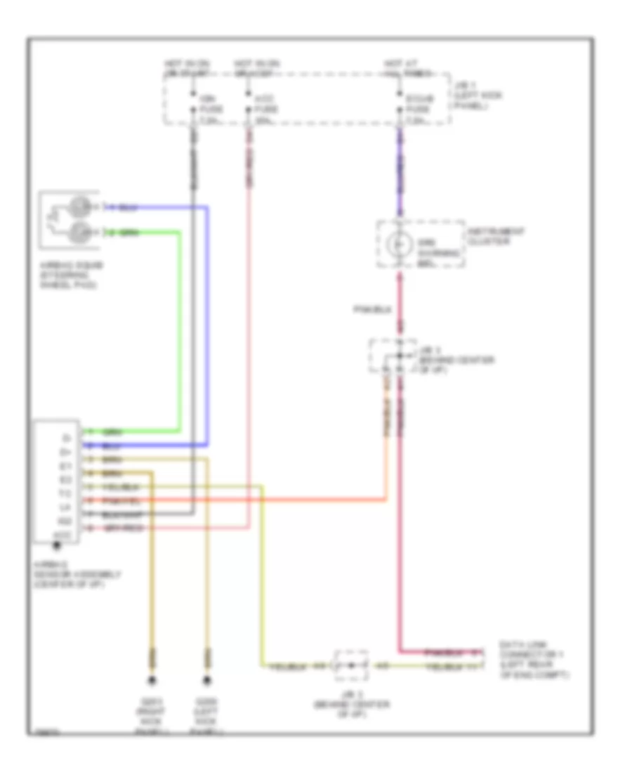
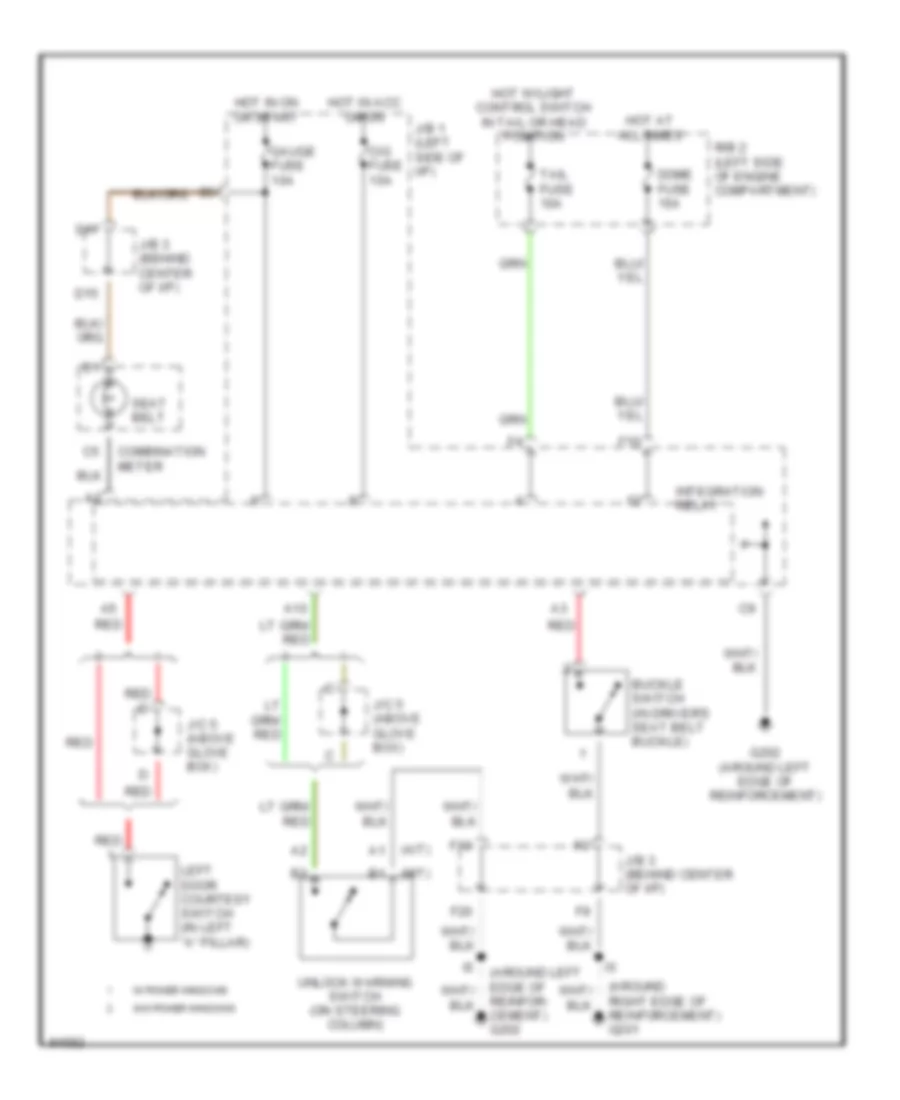
SUPPLEMENTAL RESTRAINTS
Supplemental Restraint Wiring Diagram for Toyota Tacoma 1997
List of elements for Supplemental Restraint Wiring Diagram for Toyota Tacoma 1997:
- Acc
- Acc fuse 15a
- Airbag sensor assembly (center of i/p)
- Airbag squib (steering wheel pad)
- Data link connector 1 (left rear of eng compt)
- Ecu-b fuse 7.5a
- G200 (left kick panel)
- G203 (right kick panel)
- Hot at all times
- Hot in on or accy
- Hot in on or start
- Ig2
- Ign fuse 7.5a
- Instrument cluster
- J/b 1 (left kick panel)
- J/b 3 (behind center of i/p)
- Srs warning ind
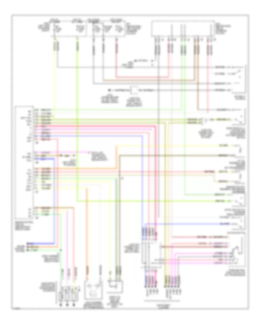
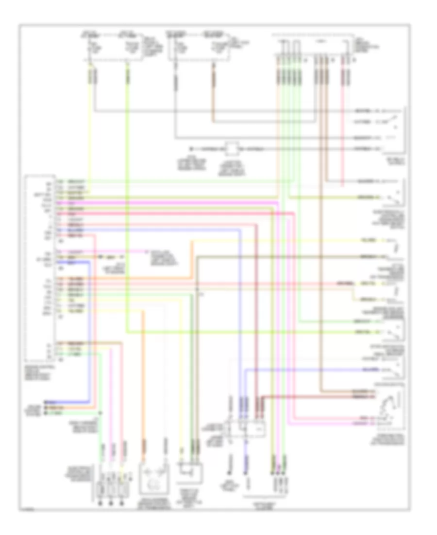
TRANSMISSION
2.4L
2.4L, Overdrive Wiring Diagram for Toyota Tacoma 1997
List of elements for 2.4L, Overdrive Wiring Diagram for Toyota Tacoma 1997:
- (w/ tach)
- (w/o tach)
- A5 d1
- C12
- C13
- Canada
- Cig fuse 15a
- Combination meter
- Cruise control ecu (on right kick panel)
- D13
- D15
- D16
- D17
- D18
- D19
- Diode (behind top center of dash)
- Diode (behind top right side of dash)
- F19
- F20
- G201 (right side of dash)
- Guage fuse 10a
- Hot in accy or on
- Hot in on or start
- J/b 1 (behind dash, left side of steering column)
- J/b 3 (behind dash, above steering column)
- Junction connector 2 (behind left side of dash)
- Junction connector 4 (behind left side of dash)
- Junction connector 6 (above glove box) (w/ cruise control only)
- O/d cut relay (on right side of engine compt) (w/ cruise control)
- O/d main switch
- O/d off
- O/d solenoid (on transmission)
- Park/ neutral position switch (on transmission)
- Pnk
- Usa
4WD Wiring Diagram, with 2-4 Select Switch for Toyota Tacoma 1997
List of elements for 4WD Wiring Diagram, with 2-4 Select Switch for Toyota Tacoma 1997:
- (i/p harness, upper right side of dash) i10
- 2-4
- 2-4 select motor (on transmission)
- 2-4 select switch
- 4wd
- 4wd ecu (upper left kick panel)
- 4wd fuse 15a
- 4wd ind
- A/t ind switch
- A/t parking ind
- A10
- Abs ecu (below center of dash)
- Add indicator switch (left side of engine)
- B12
- C10
- C12
- C13
- D10
- D12
- D14
- D17
- D19
- Detection switch (transfer l4 position) (on trans- mission)
- Detection switch (transfer neutral position) (on trans- mission)
- Detection switch (transfer position) (on trans- mission)
- Engine control module (behind right side of dash)
- Exi
- Exi3
- F18
- F20
- Floor a/t
- Floor a/t only
- G102 (left front shock tower)
- G201 (right side of dash)
- G202 (left end of dash)
- Gauge fuse 10a
- Gnd
- Hot in run or start
- I10
- Ind
- Instrument cluster
- J/b 1 (left kick panel)
- J/b 3 (center of i/p)
- J/c 1 (left front of engine compt)
- J/c 4 (top left side of dash)
- J/c 6 (top right side of dash)
- J/c 7 (upper right side of dash)
- M/t
- Park/ neutral position switch
- Red
- Rl1
- Rl2
- Spd
- Tfn
- Th+
- Th-
- Vehicle speed sensor
- Vsv 2 (add) (left front of engine compt)
- Vsv 4 (add) (left front of engine compt)
- W/ abs
- W/o abs
4WD Wiring Diagram, without 2-4 Select Switch for Toyota Tacoma 1997
List of elements for 4WD Wiring Diagram, without 2-4 Select Switch for Toyota Tacoma 1997:
- (on trans- mission)
- 2.7l
- 3.4l a/t
- 3.4l m/t
- 4wd
- 4wd control ecu (w/ rear diff lock) (upper left kick panel)
- 4wd fuse 15a
- 4wd ind
- :floor a/t only
- :w/ abs
- :w/ add control relay
- :w/ rear diff lock
- :w/o abs
- :w/o add control relay
- :w/o rear diff lock
- A/t parking ind
- A10
- Abs ecu (below
- Abs ecu (below center of dash)
- Add control relay (upper right kick panel)
- Add indicator switch (left side of engine)
- B12
- C10
- C13
- Center of dash)
- D14
- D17
- D19
- Detection switch (transfer l4 position) (on trans- mission)
- Detection switch (transfer neutral position)
- Detection switch (transfer position) (on trans- mission)
- Engine control module (behind right side of dash)
- Exi
- Exi3
- F18
- F20
- From instrument cluster (diagram 1 of 1)
- G102 (left front shock tower)
- G201 (right side of dash)
- Gauge fuse 10a
- Hot in on or start
- I10
- I10 (i/p harn, upper right side
- Instrument cluster
- J/b 1 (left kick panel)
- J/b 3 (center of i/p)
- J/c 1 (left front of engine compt)
- J/c 6 (top right side of dash)
- J/c 7 (upper right side of dash)
- Of dash)
- Park/neutral position switch (a/t indicator switch) (transmission)
- Tfn
- To add indicator switch (diagram 1 of 1)
- Vsv 2 (add) (left front of engine compt)
- Vsv 4 (add) (left front of engine compt)
Rear Differential Lock Wiring Diagram for Toyota Tacoma 1997
List of elements for Rear Differential Lock Wiring Diagram for Toyota Tacoma 1997:
- (speedometer)
- 3.4l
- 4wd
- 4wd control ecu (upper left kick panel)
- 4wd fuse 15a
- A10
- Abs ecu (below center of dash)
- B12
- C10
- C12
- C13
- D10
- D12
- D15
- D17
- Detection switch (transfer l4 position) (on transmission)
- Except 3.4l
- Exi2
- Exi3
- F18
- F20
- Free
- G201 (right side of dash)
- G202 (left end of dash)
- Gauge fuse 10a
- Gnd
- Hot in on or start
- I10
- Instrument cluster
- Integration relay
- J/b 1 (left kick panel)
- J/b 3 (behind center of i/p)
- J/c 2 (upper left side of dash)
- J/c 5 (top right side of dash)
- J/c 6 (top right side of dash)
- J/c 7 (upper right side of dash)
- Limit switch
- Lock
- Rear differential lock switch
- Rear differential lock detection switch
- Rear differential lock indicator
- Rear differential lock motor
- Rel1
- Rel2
- Rlp
- Spd
- Vehicle speed sensor
- W/ abs
- W/o abs
Transfer Case Wiring Diagram, with 2-4 Select Switch for Toyota Tacoma 1997
List of elements for Transfer Case Wiring Diagram, with 2-4 Select Switch for Toyota Tacoma 1997:
- (i/p harness, upper right side of dash) i10
- 2-4
- 2-4 select motor (on transmission)
- 2-4 select switch
- 4wd
- 4wd ecu (upper left kick panel)
- 4wd fuse 15a
- 4wd ind
- A/t ind switch
- A/t parking ind
- A10
- Abs ecu (below center of dash)
- Add indicator switch (left side of engine)
- B12
- C10
- C12
- C13
- D10
- D12
- D14
- D17
- D19
- Detection switch (transfer l4 position) (on trans- mission)
- Detection switch (transfer neutral position) (on trans- mission)
- Detection switch (transfer position) (on trans- mission)
- Engine control module (behind right side of dash)
- Exi
- Exi3
- F18
- F20
- Floor a/t
- Floor a/t only
- G102 (left front shock tower)
- G201 (right side of dash)
- G202 (left end of dash)
- Gauge fuse 10a
- Gnd
- Hot in run or start
- I10
- Ind
- Instrument cluster
- J/b 1 (left kick panel)
- J/b 3 (center of i/p)
- J/c 1 (left front of engine compt)
- J/c 4 (top left side of dash)
- J/c 6 (top right side of dash)
- J/c 7 (upper right side of dash)
- M/t
- Park/ neutral position switch
- Red
- Rl1
- Rl2
- Spd
- Tfn
- Th+
- Th-
- Vehicle speed sensor
- Vsv 2 (add) (left front of engine compt)
- Vsv 4 (add) (left front of engine compt)
- W/ abs
- W/o abs
Transfer Case Wiring Diagram, without 2-4 Select Switch for Toyota Tacoma 1997
List of elements for Transfer Case Wiring Diagram, without 2-4 Select Switch for Toyota Tacoma 1997:
- (on trans- mission)
- 2.7l
- 3.4l a/t
- 3.4l m/t
- 4wd
- 4wd control ecu (w/ rear diff lock) (upper left kick panel)
- 4wd fuse 15a
- 4wd ind
- :floor a/t only
- :w/ abs
- :w/ add control relay
- :w/ rear diff lock
- :w/o abs
- :w/o add control relay
- :w/o rear diff lock
- A/t parking ind
- A10
- Abs ecu (below
- Abs ecu (below center of dash)
- Add control relay (upper right kick panel)
- Add indicator switch (left side of engine)
- B12
- C10
- C13
- Center of dash)
- D14
- D17
- D19
- Detection switch (transfer l4 position) (on trans- mission)
- Detection switch (transfer neutral position)
- Detection switch (transfer position) (on trans- mission)
- Engine control module (behind right side of dash)
- Exi
- Exi3
- F18
- F20
- From instrument cluster (diagram 1 of 1)
- G102 (left front shock tower)
- G201 (right side of dash)
- Gauge fuse 10a
- Hot in on or start
- I10
- I10 (i/p harn, upper right side
- Instrument cluster
- J/b 1 (left kick panel)
- J/b 3 (center of i/p)
- J/c 1 (left front of engine compt)
- J/c 6 (top right side of dash)
- J/c 7 (upper right side of dash)
- Of dash)
- Park/neutral position switch (a/t indicator switch) (transmission)
- Tfn
- To add indicator switch (diagram 1 of 1)
- Vsv 2 (add) (left front of engine compt)
- Vsv 4 (add) (left front of engine compt)
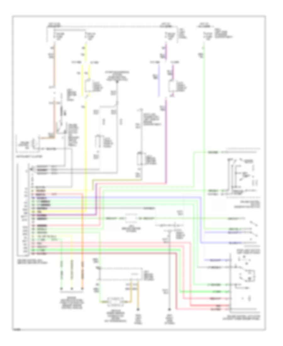
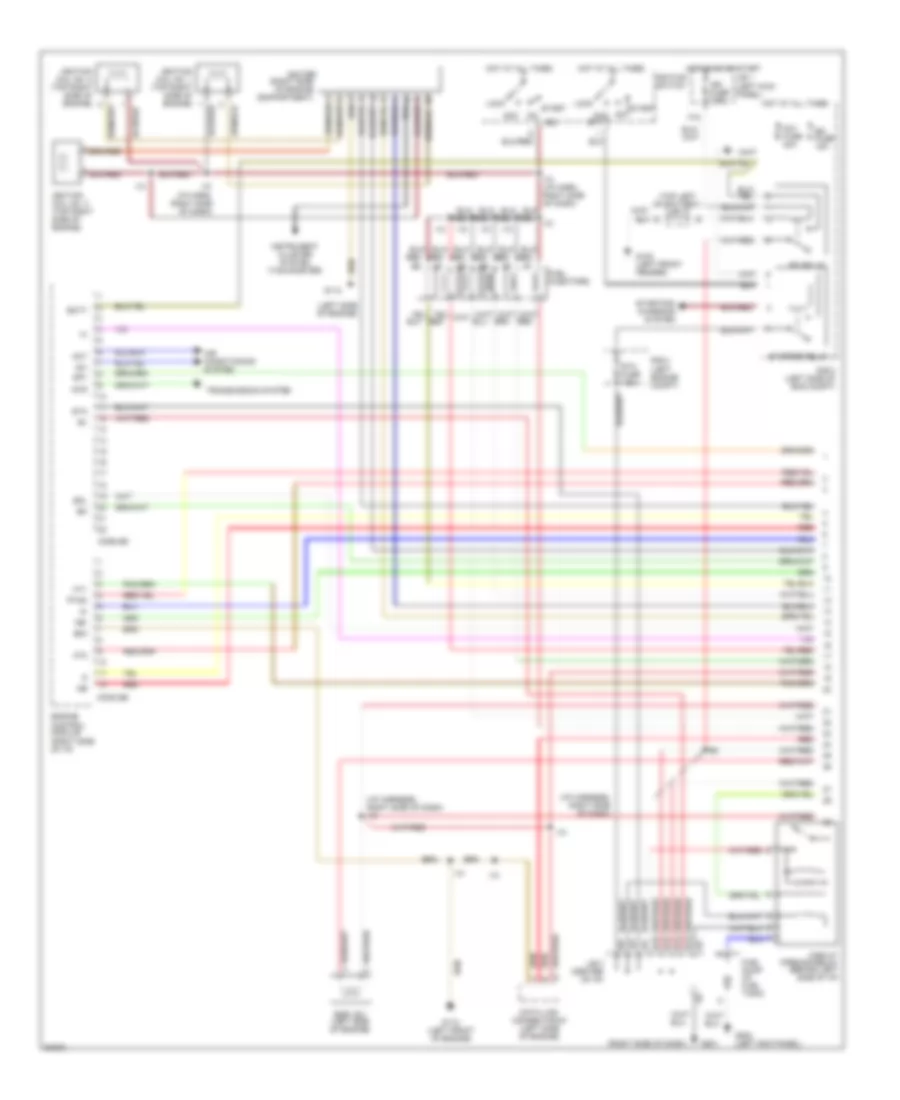
2.7L
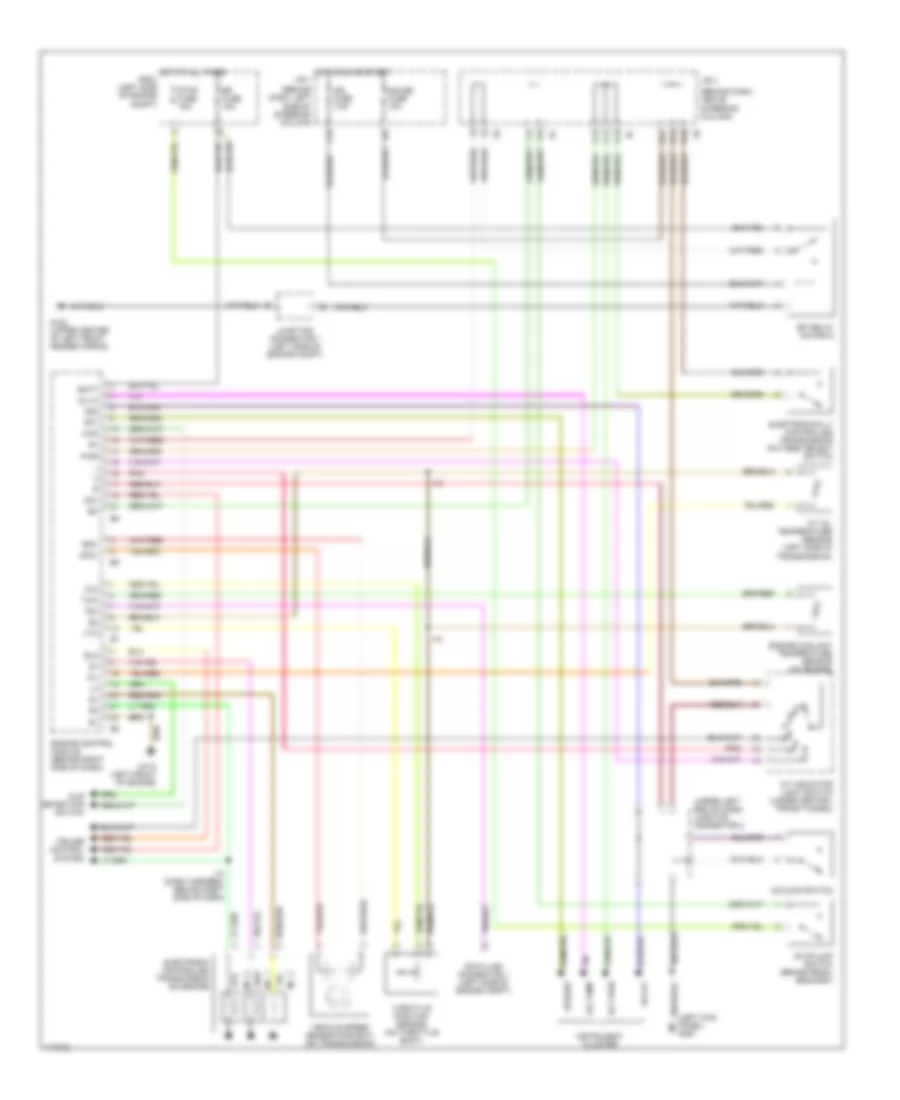
2.7L, A/T Wiring Diagram for Toyota Tacoma 1997
List of elements for 2.7L, A/T Wiring Diagram for Toyota Tacoma 1997:
- (behind dash, above steering column)
- (behind dash, left
- (left kick panel) g200
- (upper left end of dash) junction connector 4
- 4wd
- 4wd detection switch
- A/t indicator light switch (under central trans tunnel)
- A/t oil temperature sensor (left side of transmission)
- Batt
- C11
- C12
- C13
- Cruise control system
- D14
- D16
- D17
- Data link connector 1 (left side of engine compt)
- Ect pwr
- Efi fuse 15a
- Efi relay (on r/b 2)
- Electronic controlled transmission solenoids
- Electronically controlled transmission pattern select switch
- Engine control module (behind right side of dash)
- Engine coolant temperature sensor (on engine)
- F15
- G102 (upper center of left front fender apron)
- G110 (left front of engine)
- Gauge fuse 10a
- Hot at all times r/b 2 (left side of engine compt)
- Hot in on or start j/b 1
- I10
- I10 (dash harness, behind right side of dash)
- Idl0
- Ign fuse 7.5a
- Instrument cluster
- J/b 3
- Junction connector 1 (left side of engine compt)
- No. 1
- No. 2
- No. 3
- O/d main switch
- Od off
- Od1
- Od2
- Oil
- Oil temp
- Oil-w
- Pnk
- Pwr
- Side of steering column)
- Sp1
- Sp2+
- Sp2-
- Speedo
- Stop fuse 15a
- Stoplamp switch (brake pedal bracket)
- Te1
- Throttle position sensor (on throttle body)
- Thw
- Vcc
- Vehicle speed sensor (for ect) (on transmission)
- Vta
4WD Wiring Diagram, with 2-4 Select Switch for Toyota Tacoma 1997
List of elements for 4WD Wiring Diagram, with 2-4 Select Switch for Toyota Tacoma 1997:
- (i/p harness, upper right side of dash) i10
- 2-4
- 2-4 select motor (on transmission)
- 2-4 select switch
- 4wd
- 4wd ecu (upper left kick panel)
- 4wd fuse 15a
- 4wd ind
- A/t ind switch
- A/t parking ind
- A10
- Abs ecu (below center of dash)
- Add indicator switch (left side of engine)
- B12
- C10
- C12
- C13
- D10
- D12
- D14
- D17
- D19
- Detection switch (transfer l4 position) (on trans- mission)
- Detection switch (transfer neutral position) (on trans- mission)
- Detection switch (transfer position) (on trans- mission)
- Engine control module (behind right side of dash)
- Exi
- Exi3
- F18
- F20
- Floor a/t
- Floor a/t only
- G102 (left front shock tower)
- G201 (right side of dash)
- G202 (left end of dash)
- Gauge fuse 10a
- Gnd
- Hot in run or start
- I10
- Ind
- Instrument cluster
- J/b 1 (left kick panel)
- J/b 3 (center of i/p)
- J/c 1 (left front of engine compt)
- J/c 4 (top left side of dash)
- J/c 6 (top right side of dash)
- J/c 7 (upper right side of dash)
- M/t
- Park/ neutral position switch
- Red
- Rl1
- Rl2
- Spd
- Tfn
- Th+
- Th-
- Vehicle speed sensor
- Vsv 2 (add) (left front of engine compt)
- Vsv 4 (add) (left front of engine compt)
- W/ abs
- W/o abs
4WD Wiring Diagram, without 2-4 Select Switch for Toyota Tacoma 1997
List of elements for 4WD Wiring Diagram, without 2-4 Select Switch for Toyota Tacoma 1997:
- (on trans- mission)
- 2.7l
- 3.4l a/t
- 3.4l m/t
- 4wd
- 4wd control ecu (w/ rear diff lock) (upper left kick panel)
- 4wd fuse 15a
- 4wd ind
- :floor a/t only
- :w/ abs
- :w/ add control relay
- :w/ rear diff lock
- :w/o abs
- :w/o add control relay
- :w/o rear diff lock
- A/t parking ind
- A10
- Abs ecu (below
- Abs ecu (below center of dash)
- Add control relay (upper right kick panel)
- Add indicator switch (left side of engine)
- B12
- C10
- C13
- Center of dash)
- D14
- D17
- D19
- Detection switch (transfer l4 position) (on trans- mission)
- Detection switch (transfer neutral position)
- Detection switch (transfer position) (on trans- mission)
- Engine control module (behind right side of dash)
- Exi
- Exi3
- F18
- F20
- From instrument cluster (diagram 1 of 1)
- G102 (left front shock tower)
- G201 (right side of dash)
- Gauge fuse 10a
- Hot in on or start
- I10
- I10 (i/p harn, upper right side
- Instrument cluster
- J/b 1 (left kick panel)
- J/b 3 (center of i/p)
- J/c 1 (left front of engine compt)
- J/c 6 (top right side of dash)
- J/c 7 (upper right side of dash)
- Of dash)
- Park/neutral position switch (a/t indicator switch) (transmission)
- Tfn
- To add indicator switch (diagram 1 of 1)
- Vsv 2 (add) (left front of engine compt)
- Vsv 4 (add) (left front of engine compt)
Rear Differential Lock Wiring Diagram for Toyota Tacoma 1997
List of elements for Rear Differential Lock Wiring Diagram for Toyota Tacoma 1997:
- (speedometer)
- 3.4l
- 4wd
- 4wd control ecu (upper left kick panel)
- 4wd fuse 15a
- A10
- Abs ecu (below center of dash)
- B12
- C10
- C12
- C13
- D10
- D12
- D15
- D17
- Detection switch (transfer l4 position) (on transmission)
- Except 3.4l
- Exi2
- Exi3
- F18
- F20
- Free
- G201 (right side of dash)
- G202 (left end of dash)
- Gauge fuse 10a
- Gnd
- Hot in on or start
- I10
- Instrument cluster
- Integration relay
- J/b 1 (left kick panel)
- J/b 3 (behind center of i/p)
- J/c 2 (upper left side of dash)
- J/c 5 (top right side of dash)
- J/c 6 (top right side of dash)
- J/c 7 (upper right side of dash)
- Limit switch
- Lock
- Rear differential lock switch
- Rear differential lock detection switch
- Rear differential lock indicator
- Rear differential lock motor
- Rel1
- Rel2
- Rlp
- Spd
- Vehicle speed sensor
- W/ abs
- W/o abs
Transfer Case Wiring Diagram, with 2-4 Select Switch for Toyota Tacoma 1997
List of elements for Transfer Case Wiring Diagram, with 2-4 Select Switch for Toyota Tacoma 1997:
- (i/p harness, upper right side of dash) i10
- 2-4
- 2-4 select motor (on transmission)
- 2-4 select switch
- 4wd
- 4wd ecu (upper left kick panel)
- 4wd fuse 15a
- 4wd ind
- A/t ind switch
- A/t parking ind
- A10
- Abs ecu (below center of dash)
- Add indicator switch (left side of engine)
- B12
- C10
- C12
- C13
- D10
- D12
- D14
- D17
- D19
- Detection switch (transfer l4 position) (on trans- mission)
- Detection switch (transfer neutral position) (on trans- mission)
- Detection switch (transfer position) (on trans- mission)
- Engine control module (behind right side of dash)
- Exi
- Exi3
- F18
- F20
- Floor a/t
- Floor a/t only
- G102 (left front shock tower)
- G201 (right side of dash)
- G202 (left end of dash)
- Gauge fuse 10a
- Gnd
- Hot in run or start
- I10
- Ind
- Instrument cluster
- J/b 1 (left kick panel)
- J/b 3 (center of i/p)
- J/c 1 (left front of engine compt)
- J/c 4 (top left side of dash)
- J/c 6 (top right side of dash)
- J/c 7 (upper right side of dash)
- M/t
- Park/ neutral position switch
- Red
- Rl1
- Rl2
- Spd
- Tfn
- Th+
- Th-
- Vehicle speed sensor
- Vsv 2 (add) (left front of engine compt)
- Vsv 4 (add) (left front of engine compt)
- W/ abs
- W/o abs
Transfer Case Wiring Diagram, without 2-4 Select Switch for Toyota Tacoma 1997
List of elements for Transfer Case Wiring Diagram, without 2-4 Select Switch for Toyota Tacoma 1997:
- (on trans- mission)
- 2.7l
- 3.4l a/t
- 3.4l m/t
- 4wd
- 4wd control ecu (w/ rear diff lock) (upper left kick panel)
- 4wd fuse 15a
- 4wd ind
- :floor a/t only
- :w/ abs
- :w/ add control relay
- :w/ rear diff lock
- :w/o abs
- :w/o add control relay
- :w/o rear diff lock
- A/t parking ind
- A10
- Abs ecu (below
- Abs ecu (below center of dash)
- Add control relay (upper right kick panel)
- Add indicator switch (left side of engine)
- B12
- C10
- C13
- Center of dash)
- D14
- D17
- D19
- Detection switch (transfer l4 position) (on trans- mission)
- Detection switch (transfer neutral position)
- Detection switch (transfer position) (on trans- mission)
- Engine control module (behind right side of dash)
- Exi
- Exi3
- F18
- F20
- From instrument cluster (diagram 1 of 1)
- G102 (left front shock tower)
- G201 (right side of dash)
- Gauge fuse 10a
- Hot in on or start
- I10
- I10 (i/p harn, upper right side
- Instrument cluster
- J/b 1 (left kick panel)
- J/b 3 (center of i/p)
- J/c 1 (left front of engine compt)
- J/c 6 (top right side of dash)
- J/c 7 (upper right side of dash)
- Of dash)
- Park/neutral position switch (a/t indicator switch) (transmission)
- Tfn
- To add indicator switch (diagram 1 of 1)
- Vsv 2 (add) (left front of engine compt)
- Vsv 4 (add) (left front of engine compt)
3.4L
3.4L, A/T Wiring Diagram, with Column Shift for Toyota Tacoma 1997
List of elements for 3.4L, A/T Wiring Diagram, with Column Shift for Toyota Tacoma 1997:
- 2 ind
- A/t oil temperature sensor (on transmission)
- Batt (b+)
- C12
- C13
- Cig fuse 15a
- Cruise control system
- D ind
- D16
- D17
- Data link connector (left side of engine compt)
- E1 (grd)
- E12
- E13
- Ect pwr
- Efi fuse 15a
- Efi relay (on r/b 2)
- Electronic controlled transmission solenoids
- Electronically controlled transmission pattern select switch
- Engine control module (behind right side of dash)
- Engine coolant temperature sensor (on engine)
- F15
- G102 (upper center of left front fender apron)
- G110 (left front of engine)
- G200 (left kick panel)
- Gauge fuse 10a
- Hot at all times
- Hot in run or accy
- Hot in run or start
- I10
- I10 (dash harness, behind right side of dash)
- Idl0
- Ign fuse 7.5a
- Instrument cluster
- J/b 1 (behind dash, left side of steering column)
- J/b 3 (behind dash, above steering column)
- Junction connector 1 (left side of engine compt)
- Junction connector 4 (upper left end of dash)
- Junction connector 8 (right end of dash)
- L ind
- N ind
- No. 1
- No. 2
- No. 3
- O/d main switch
- Od off
- Od1
- Od2
- Oil
- P ind
- Park/neutral position switch (on transmission)
- Pnk
- Pwr
- R ind
- R/b 2 (left side of engine compt)
- Sp1
- Sp2+
- Sp2-
- Speedo
- Stop fuse 15a
- Stoplamp switch (on brake pedal bracket)
- Te1
- Throttle position sensor (on throttle body)
- Thw
- Vcc
- Vehicle speed sensor (for ect) (on transmission)
- Vta
3.4L, A/T Wiring Diagram, with Floor Shift for Toyota Tacoma 1997
List of elements for 3.4L, A/T Wiring Diagram, with Floor Shift for Toyota Tacoma 1997:
- A/t oil temperature sensor (on transmission)
- Batt (b+)
- C11
- C12
- C13
- Cruise control system
- D14
- D16
- D17
- Data link connector (left side of engine compt)
- E1 (grd)
- E12
- E13
- Ect pwr
- Efi fuse 15a
- Efi relay (on r/b 2)
- Electronic controlled transmission solenoids
- Electronically controlled transmission pattern select switch
- Engine control module (behind right side of dash)
- Engine coolant temperature sensor (on engine)
- F15
- G102 (upper center of left front fender apron)
- G110 (left front of engine)
- G200 (left kick panel)
- Gauge fuse 10a
- Hot at all times
- Hot in run or start
- I10
- I10 (dash harness, behind right side of dash)
- Idl0
- Ign fuse 7.5a
- Instrument cluster
- J/b 1 (left kick panel)
- J/b 3 (behind combination meter)
- Junction connector (upper left end of dash)
- Junction connector 1 (left side of engine compt)
- No. 1
- No. 2
- No. 3
- O/d main switch
- Od off
- Od1
- Od2
- Oil
- Oil temp
- Oil-w
- Park/neutral position switch (on transmission)
- Pnk
- Pwr
- Relay block 2 (left side of engine compt)
- Sp1
- Sp2+
- Sp2-
- Speedo
- Stop fuse 15a
- Stoplamp switch (on brake pedal bracket)
- Te1
- Throttle position sensor (on throttle body)
- Thw
- Vcc
- Vehicle speed sensor (for ect) (on transmission)
- Vta
4WD Wiring Diagram, with 2-4 Select Switch for Toyota Tacoma 1997
List of elements for 4WD Wiring Diagram, with 2-4 Select Switch for Toyota Tacoma 1997:
- (i/p harness, upper right side of dash) i10
- 2-4
- 2-4 select motor (on transmission)
- 2-4 select switch
- 4wd
- 4wd ecu (upper left kick panel)
- 4wd fuse 15a
- 4wd ind
- A/t ind switch
- A/t parking ind
- A10
- Abs ecu (below center of dash)
- Add indicator switch (left side of engine)
- B12
- C10
- C12
- C13
- D10
- D12
- D14
- D17
- D19
- Detection switch (transfer l4 position) (on trans- mission)
- Detection switch (transfer neutral position) (on trans- mission)
- Detection switch (transfer position) (on trans- mission)
- Engine control module (behind right side of dash)
- Exi
- Exi3
- F18
- F20
- Floor a/t
- Floor a/t only
- G102 (left front shock tower)
- G201 (right side of dash)
- G202 (left end of dash)
- Gauge fuse 10a
- Gnd
- Hot in run or start
- I10
- Ind
- Instrument cluster
- J/b 1 (left kick panel)
- J/b 3 (center of i/p)
- J/c 1 (left front of engine compt)
- J/c 4 (top left side of dash)
- J/c 6 (top right side of dash)
- J/c 7 (upper right side of dash)
- M/t
- Park/ neutral position switch
- Red
- Rl1
- Rl2
- Spd
- Tfn
- Th+
- Th-
- Vehicle speed sensor
- Vsv 2 (add) (left front of engine compt)
- Vsv 4 (add) (left front of engine compt)
- W/ abs
- W/o abs
4WD Wiring Diagram, without 2-4 Select Switch for Toyota Tacoma 1997
List of elements for 4WD Wiring Diagram, without 2-4 Select Switch for Toyota Tacoma 1997:
- (on trans- mission)
- 2.7l
- 3.4l a/t
- 3.4l m/t
- 4wd
- 4wd control ecu (w/ rear diff lock) (upper left kick panel)
- 4wd fuse 15a
- 4wd ind
- :floor a/t only
- :w/ abs
- :w/ add control relay
- :w/ rear diff lock
- :w/o abs
- :w/o add control relay
- :w/o rear diff lock
- A/t parking ind
- A10
- Abs ecu (below
- Abs ecu (below center of dash)
- Add control relay (upper right kick panel)
- Add indicator switch (left side of engine)
- B12
- C10
- C13
- Center of dash)
- D14
- D17
- D19
- Detection switch (transfer l4 position) (on trans- mission)
- Detection switch (transfer neutral position)
- Detection switch (transfer position) (on trans- mission)
- Engine control module (behind right side of dash)
- Exi
- Exi3
- F18
- F20
- From instrument cluster (diagram 1 of 1)
- G102 (left front shock tower)
- G201 (right side of dash)
- Gauge fuse 10a
- Hot in on or start
- I10
- I10 (i/p harn, upper right side
- Instrument cluster
- J/b 1 (left kick panel)
- J/b 3 (center of i/p)
- J/c 1 (left front of engine compt)
- J/c 6 (top right side of dash)
- J/c 7 (upper right side of dash)
- Of dash)
- Park/neutral position switch (a/t indicator switch) (transmission)
- Tfn
- To add indicator switch (diagram 1 of 1)
- Vsv 2 (add) (left front of engine compt)
- Vsv 4 (add) (left front of engine compt)
Rear Differential Lock Wiring Diagram for Toyota Tacoma 1997
List of elements for Rear Differential Lock Wiring Diagram for Toyota Tacoma 1997:
- (speedometer)
- 3.4l
- 4wd
- 4wd control ecu (upper left kick panel)
- 4wd fuse 15a
- A10
- Abs ecu (below center of dash)
- B12
- C10
- C12
- C13
- D10
- D12
- D15
- D17
- Detection switch (transfer l4 position) (on transmission)
- Except 3.4l
- Exi2
- Exi3
- F18
- F20
- Free
- G201 (right side of dash)
- G202 (left end of dash)
- Gauge fuse 10a
- Gnd
- Hot in on or start
- I10
- Instrument cluster
- Integration relay
- J/b 1 (left kick panel)
- J/b 3 (behind center of i/p)
- J/c 2 (upper left side of dash)
- J/c 5 (top right side of dash)
- J/c 6 (top right side of dash)
- J/c 7 (upper right side of dash)
- Limit switch
- Lock
- Rear differential lock switch
- Rear differential lock detection switch
- Rear differential lock indicator
- Rear differential lock motor
- Rel1
- Rel2
- Rlp
- Spd
- Vehicle speed sensor
- W/ abs
- W/o abs
Transfer Case Wiring Diagram, with 2-4 Select Switch for Toyota Tacoma 1997
List of elements for Transfer Case Wiring Diagram, with 2-4 Select Switch for Toyota Tacoma 1997:
- (i/p harness, upper right side of dash) i10
- 2-4
- 2-4 select motor (on transmission)
- 2-4 select switch
- 4wd
- 4wd ecu (upper left kick panel)
- 4wd fuse 15a
- 4wd ind
- A/t ind switch
- A/t parking ind
- A10
- Abs ecu (below center of dash)
- Add indicator switch (left side of engine)
- B12
- C10
- C12
- C13
- D10
- D12
- D14
- D17
- D19
- Detection switch (transfer l4 position) (on trans- mission)
- Detection switch (transfer neutral position) (on trans- mission)
- Detection switch (transfer position) (on trans- mission)
- Engine control module (behind right side of dash)
- Exi
- Exi3
- F18
- F20
- Floor a/t
- Floor a/t only
- G102 (left front shock tower)
- G201 (right side of dash)
- G202 (left end of dash)
- Gauge fuse 10a
- Gnd
- Hot in run or start
- I10
- Ind
- Instrument cluster
- J/b 1 (left kick panel)
- J/b 3 (center of i/p)
- J/c 1 (left front of engine compt)
- J/c 4 (top left side of dash)
- J/c 6 (top right side of dash)
- J/c 7 (upper right side of dash)
- M/t
- Park/ neutral position switch
- Red
- Rl1
- Rl2
- Spd
- Tfn
- Th+
- Th-
- Vehicle speed sensor
- Vsv 2 (add) (left front of engine compt)
- Vsv 4 (add) (left front of engine compt)
- W/ abs
- W/o abs
Transfer Case Wiring Diagram, without 2-4 Select Switch for Toyota Tacoma 1997
List of elements for Transfer Case Wiring Diagram, without 2-4 Select Switch for Toyota Tacoma 1997:
- (on trans- mission)
- 2.7l
- 3.4l a/t
- 3.4l m/t
- 4wd
- 4wd control ecu (w/ rear diff lock) (upper left kick panel)
- 4wd fuse 15a
- 4wd ind
- :floor a/t only
- :w/ abs
- :w/ add control relay
- :w/ rear diff lock
- :w/o abs
- :w/o add control relay
- :w/o rear diff lock
- A/t parking ind
- A10
- Abs ecu (below
- Abs ecu (below center of dash)
- Add control relay (upper right kick panel)
- Add indicator switch (left side of engine)
- B12
- C10
- C13
- Center of dash)
- D14
- D17
- D19
- Detection switch (transfer l4 position) (on trans- mission)
- Detection switch (transfer neutral position)
- Detection switch (transfer position) (on trans- mission)
- Engine control module (behind right side of dash)
- Exi
- Exi3
- F18
- F20
- From instrument cluster (diagram 1 of 1)
- G102 (left front shock tower)
- G201 (right side of dash)
- Gauge fuse 10a
- Hot in on or start
- I10
- I10 (i/p harn, upper right side
- Instrument cluster
- J/b 1 (left kick panel)
- J/b 3 (center of i/p)
- J/c 1 (left front of engine compt)
- J/c 6 (top right side of dash)
- J/c 7 (upper right side of dash)
- Of dash)
- Park/neutral position switch (a/t indicator switch) (transmission)
- Tfn
- To add indicator switch (diagram 1 of 1)
- Vsv 2 (add) (left front of engine compt)
- Vsv 4 (add) (left front of engine compt)
WARNING SYSTEMS
Warning System Wiring Diagrams for Toyota Tacoma 1997
List of elements for Warning System Wiring Diagrams for Toyota Tacoma 1997:
- (a/t)
- (around left edge of reinfor- cement) g202
- (around right edge of reinforcement) g201
- (m/t)
- A10
- Buckle switch (in driver's seat belt buckle)
- Cig fuse 15a
- Combination meter
- D15
- D17
- Dome fuse 15a
- F10
- F13
- F20
- G202 (around left edge of reinforcement)
- Gauge fuse 10a
- Hot at all times
- Hot in acc or on
- Hot in on or start
- Hot w/light control switch in tail or head position
- Integration relay
- J/b 1 (left side of i/p)
- J/b 3 (behind center of i/p)
- J/b 3 (behind center of i/p)
- J/c 5 (above glove box)
- Left door courtesy switch (in left "a" pillar)
- R/b 2 (left side of engine compartment)
- Red
- Red d
- Seat belt
- Tail fuse 10a
- Unlock warning switch (on steering column)
- W/ power windows
- W/o power windows
WIPER/WASHER
Wiper/Washer Wiring Diagram for Toyota Tacoma 1997
List of elements for Wiper/Washer Wiring Diagram for Toyota Tacoma 1997:
- (1997)
- (1998-2000)
- B10
- Combination switch
- F10 (1997)
- F16 (1998-2000)
- F18 (1998-2000)
- F20 (1997)
- G201 (right side of dash)
- G202 (left end of dash)
- High
- Hot in on or start
- I12
- Int
- J/b 1 (behind dash, left of steering column)
- J/b 3 (left) (behind dash above steering column)
- Low/ mist
- Off
- Solid state
- Wash
- Washer motor (in washer fluid reservoir)
- Wiper fuse 20a
- Wiper motor (on right side of firewall)
- Wiper/ washer switch

 Čeština
 Dansk
Dansk Deutsch
 Ελληνικά
 English
 English
 Español
 Suomi
Suomi Français
 Français
 עברית
עברית Hrvatski
 Magyar
 Italiano
 日本語
日本語 한국어
한국어 Nederlands
 Polski
 Português
 Português
 Română
 Русский
 Slovenčina
 Svenska
 Türkçe
 中文 (中国)