STARTING/CHARGING
Charging Wiring Diagram for Audi Q5 Premium 2013

List of elements for Charging Wiring Diagram for Audi Q5 Premium 2013:
- (left side of luggage compt) battery monitoring control module
- 2.0l
- 3.0l
- Battery
- Battery interrupt igniter
- Battery jump start terminal (terminal 30 wire junction 2) (in center plenum chamber)
- Computer data lines system
- Data bus on board diagnostic interface
- Fuse panel a (on battery positive terminal)
- G624 (in luggage compt near starter battery)
- Generator & voltage regulator
- Instrument cluster control module
- Starter
- T17e
- T17r
- T5l
- Voltage stabilizer (w/ start/stop system) (right side of luggage compt)
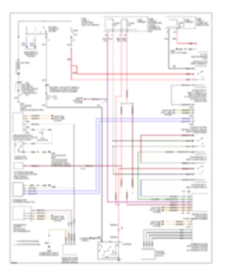
Starting Wiring Diagram for Audi Q5 Premium 2013
List of elements for Starting Wiring Diagram for Audi Q5 Premium 2013:
- (above clutch pedal assembly)
- 10a
- 2.0l
- 3.0l
- 3.0l 2.0l
- Access/start authorization button
- Battery
- Battery interrupt igniter
- Battery jump start terminal (terminal 30 wire junction 2) (in center plenum chamber)
- Battery monitoring control module (left side of luggage compt)
- Charging circuit
- Clutch position sensor (m/t)
- Comfort system central control module (right side of trunk)
- Computer data lines system
- Engine control module (ecm) (in left plenum chamber)
- Engine controls system
- Fuse 110a
- Fuse 3 5a
- Fuse 5a
- Fuse 9 5a
- Fuse carrier 1
- Fuse panel a (on battery positive terminal)
- Fuse panel b (driver's side plenum chamber on electronics box)
- Fuse panel c (lower left side of dash)
- G624 (in luggage compt near starter battery)
- G639 (left kick panel)
- G668
- G688 (under right front of center console)
- G887 (w/ navigation) g688 (w/o navigation) (w/o navigation: under right front of center console)
- Ignition/ starter switch
- Navigation
- Nca
- Red
- Selector lever sensor system control module
- Start/stop mode button
- Starter
- Starter relay (relay/fuse panel b)
- Starter relay 2 (relay/fuse panel b)
- Steering column electronic systems control module (on steering column)
- T16b
- T16f
- T17c
- T17q
- T32a
- T32b
- T32c
- T32d
- T32e
- T5i
- T94
- Transmission control module (tcm) (on transmission)
- Vehicle electrical system control module (left side of dash)
- Voltage stabilizer (w/ start/stop system) (right side of luggage compt)
- W/ start/stop system
- W/o
- W/o start/stop system