STARTING/CHARGING
4.0L
4.0L, Charging Wiring Diagram for Jaguar XK8 1997

List of elements for 4.0L, Charging Wiring Diagram for Jaguar XK8 1997:
- (battery ground stud) g401
- (right side of false bulkhead, in engine compartment) false bulkhead stud connector
- 1996 vftc c
- 250a
- Battery (right side of trunk)
- Bt60
- Bt61
- Bt80
- Charge warning
- Engine compartment fuse box (left front of engine compartment)
- Fc26
- Fuse 5 10a
- Generator (right front of engine compartment)
- High power protection module (in trunk, adjacent to battery)
- Hot in run & start
- Lf6
- Major instrument pack
- Note: early production vehicles with vin numbers below (vin 003300) use connector pin numbers, which differ from volume production models shown. use wire color code for pin identification on early production models.
- St1
- St10
- St2
- Starter motor (engine block)
- Suppression module (forward of generator, in engine compartment)
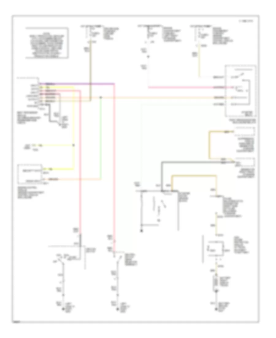
4.0L, Starting Wiring Diagram for Jaguar XK8 1997
List of elements for 4.0L, Starting Wiring Diagram for Jaguar XK8 1997:
- (battery ground stud) g401
- (left hand "a" post) g202
- (not used)
- 1996 vftc c
- 250a
- Acc i
- An1/ st11
- Battery (right side of trunk)
- Body processor module (on airbag bracket, passenger side fascia)
- Bt60
- Bt61
- Bt80
- Crank input
- Data
- Driver side fuse box (driver side fascia)
- Em10
- Em11
- Em20
- Engine compartment fuse box (left front of engine compartment)
- Engine control module (engine compartment, control module enclosure)
- Engine management fuse box (engine compartment, control module enclosure)
- False bulkhead stud connector (right side of false bulkhead, in engine compartment)
- Fc14
- Fc22
- Fc5
- Fuse 3 25a
- Fuse 5 10a
- Fuse 5 15a
- Generator (right front of engine compartment)
- High power protection module (in trunk, adjacent to battery)
- Hot at all times
- Hot in run & start
- Ignition switch
- Input
- Lf6
- Logig gnd
- Nca
- Neutral switch (gear selector assembly)
- Note: early production vehicles with vin numbers below (vin 003300) use connector pin numbers, which differ from volume production models shown. use wire color code for pin identification on early production models.
- Off
- Output
- Pwr gnd
- Right brake booster enclosure relays
- Run ii
- Security data
- St1
- St10
- St2
- St3
- Start iii
- Starter motor (engine block)
- Starter relay
- Suppression module (forward of generator, in engine compartment)