SUPPLEMENTAL RESTRAINTS
Supplemental Restraint Wiring Diagram for Chevrolet Corvette 1997
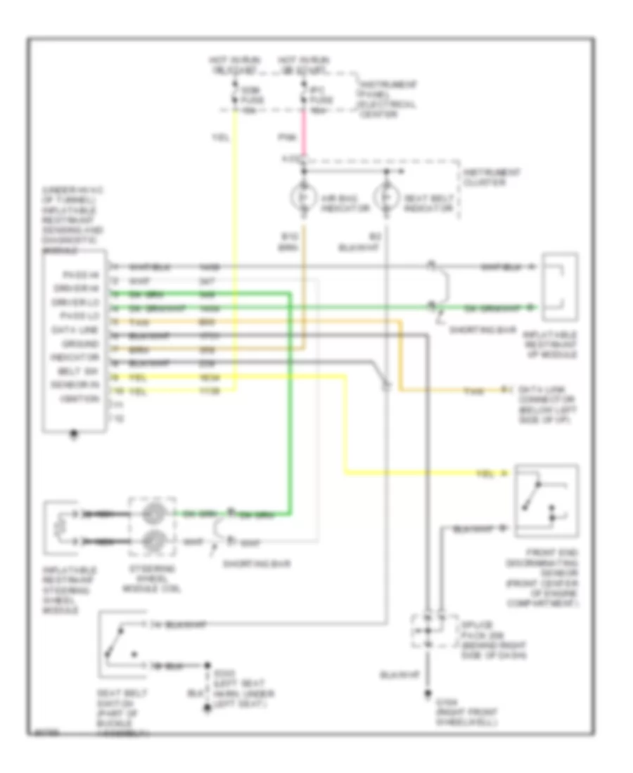
List of elements for Supplemental Restraint Wiring Diagram for Chevrolet Corvette 1997:
- (under hvac of tunnel) inflatable restraint sensing and diagnostic module
- A13
- Air bag indicator
- B12
- Belt sw
- Data line
- Data link connector (below left side of i/p)
- Driver hi
- Driver lo
- Front end discriminating sensor (front center of engine compartment)
- G104 (right front wheelwell)
- Ground
- Hot in run or start
- Ignition
- Indicator
- Inflatable restraint i/p module
- Inflatable restraint steering wheel module
- Instrument cluster
- Instrument panel electrical center
- Ipc fuse 10a
- Nca
- Nca b
- Pass hi
- Pass lo
- Pnk
- S303 (left seat harn, under left seat)
- Sdm fuse 15a
- Seat belt indicator
- Seat belt switch (part of buckle assembly)
- Sensor in
- Shorting bar
- Splice pack 208 (behind right side of dash)
- Steering wheel module coil
- Tan
 English