SUPPLEMENTAL RESTRAINTS
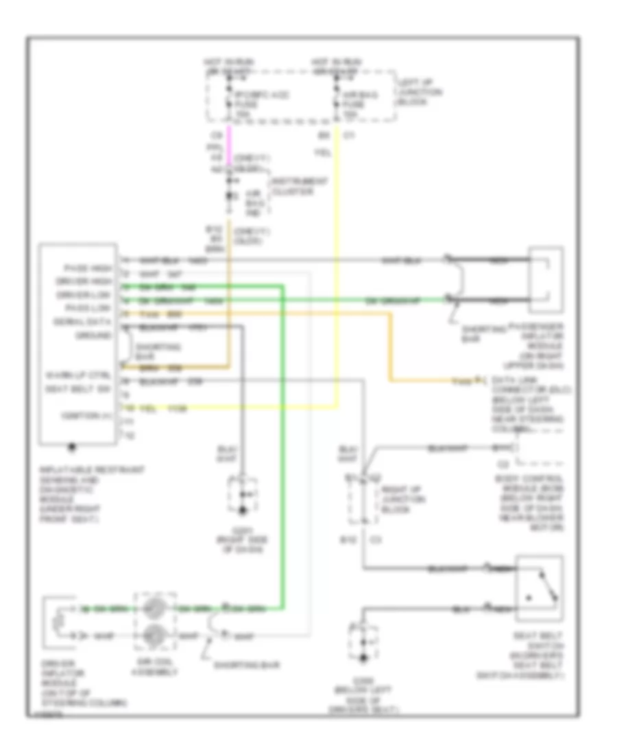
Supplemental Restraint Wiring Diagram for Chevrolet Malibu LS 1999
List of elements for Supplemental Restraint Wiring Diagram for Chevrolet Malibu LS 1999:
- (chevy) (olds)
- Air bag fuse 10a
- Air bag ind
- B11
- B12
- Body control module (bcm) (below right side of dash, near blower motor)
- Data link connector (dlc) (below left side of dash, near steering column)
- Driver high
- Driver inflator module (on top of steering column)
- Driver low
- G201 (right side of dash)
- G300 (below left side of driver's seat)
- Ground
- Hot in run or start
- Ignition (+)
- Inflatable restraint sensing and diagnostic module (under right front seat)
- Instrument cluster
- Ipc/bfc acc fuse 10a
- Left i/p junction block
- Nca
- Pass high
- Pass low
- Passenger inflat0r module (on right upper dash)
- Right i/p junction block
- Seat belt sw
- Seat belt switch (in driver's seat belt switch assembly)
- Serial data
- Shorting bar
- Sir coil assembly
- Tan
- Warn lp ctrl
 English