SUPPLEMENTAL RESTRAINTS
Supplemental Restraints Wiring Diagram for Hummer H2 2003
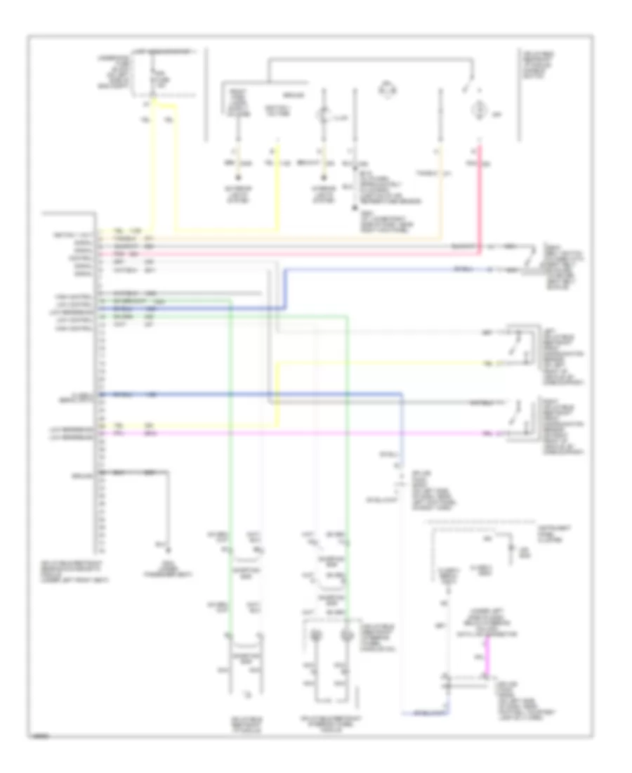
List of elements for Supplemental Restraints Wiring Diagram for Hummer H2 2003:
- (under left side of dash, below steering column) data link connector
- Air bag
- Class 2 (sdm)
- Class 2 serial data
- Control
- Exterior lights system
- G203 (at lower right side of dash, near right kick panel)
- G304 (under passenger seat)
- Ground
- High control
- Hot in run or start
- Ign
- Ignition 1 voltage
- Igniton 1 volt
- Illum
- Inflatable restraint i/p module
- Inflatable restraint i/p module disable switch
- Inflatable restraint sensing & diagnostic module (under left front seat)
- Inflatable restraint steering wheel module
- Inflatable restraint steering wheel module coil
- Instrument panel cluster
- Interior lights system
- Left inflatable restraint front discrimination sensor (on left front of vehicle, by core support)
- Low control
- Low reference
- Nca
- Nca a
- Nca b
- Off
- Pnk
- Right inflatable restraint front discrimination sensor (on right front of vehicle, by core support)
- S215 (in i/p harn, approximately 5.5 cm from junction of air temperature sensor)
- Seat belt switch (closed with seat belt buckled) (in driver seat belt buckle)
- Shorting bar
- Signal
- Sir fuse 15a
- Splice pack sp205 (on left side of dash, near footwell courtesy lamp on i/i harn)
- Splice pack sp207 (on left side of dash, near left kick panel, on body harn)
- Underhood fuse block (on left side of eng compt)
 English