SUPPLEMENTAL RESTRAINTS
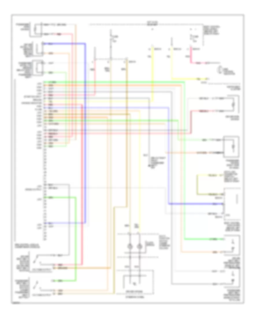
Supplemental Restraints Wiring Diagram for Hyundai Tiburon GT 2006
List of elements for Supplemental Restraints Wiring Diagram for Hyundai Tiburon GT 2006:
- (below right front passenger seat) g09
- Air bag indicator
- Atd
- Bcm-ai
- Bcm-im
- Bcm-jm
- Body control module box (behind left side of dash)
- Clock spring
- Crash output
- Data link connector (partial) (below left side of dash)
- Driver air bag
- Driver satellite sensor (below driver seat)
- Driver seat belt buckle switch (on driver seat belt buckle)
- Driver seat belt pretensioner (base of left ``b" pillar)
- Driver side air bag
- Fuse 10a
- Fuse 15a
- Ground
- High
- Hot in on or start
- Instrument cluster
- K-line
- Low
- M10-2
- Multi- function switch (under steering column)
- Nca
- Passenger air bag (right side of dash)
- Passenger satellite sensor (below right front passenger seat)
- Passenger seat belt buckle switch (under passenger seat bottom)
- Passenger seat belt pretensioner (base of right ``b" pillar)
- Passenger side air bag
- Pnk
- Red
- Srs (air bag) indicator
- Srs control module (under rear console)
- Start/on input
- Steering wheel
- Voltage output
 English