SUPPLEMENTAL RESTRAINTS
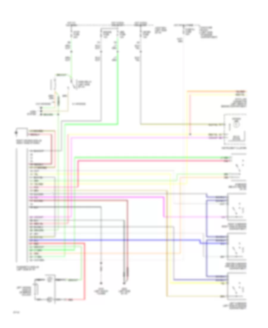
Supplemental Restraint Wiring Diagram for Mazda MX-3 1994
List of elements for Supplemental Restraint Wiring Diagram for Mazda MX-3 1994:
- Abs fuse 10a
- Air bag ind
- Center d-sensor (center of engine compartment)
- Data link connector (left rear of engine compartment)
- Diagnostic module (left side of i/p)
- Engine fuse 10a
- Fuse inj fuse 30a
- G102 (left shock tower)
- G202 (left side of i/p)
- Horn relay (left side of i/p)
- Horn system
- Hot at all times
- Hot in run and start
- Instrument cluster
- Joint box (left side of i/p)
- Left air bag module (steering column)
- Left d-sensor (left side of engine compartment)
- Main fuse block (left side of engine compartment)
- Meter fuse 15a
- Nca
- Pnk
- Red
- Right air bag module (right side of dash)
- Right d-sensor (right side of engine compartment)
- S-sensor (below center of i/p)
- Solid state
- Stop fuse 20a
- W/ air bags
- W/o air bags
 English