SUPPLEMENTAL RESTRAINTS
Supplemental Restraints Wiring Diagram (1 of 3) for Mitsubishi Galant SE 2010

List of elements for Supplemental Restraints Wiring Diagram (1 of 3) for Mitsubishi Galant SE 2010:
- C-121
- C-211
- C-214
- Combination meter
- Connector lock switch (connector coupled: on) (connector uncoupled: off)
- Cpu
- Data
- Data link connector (under left side of dash)
- Driver's side air bag drive
- Front impact
- Fuse 10a
- Fuse 7.5a
- G12 (left side of engine compt)
- G6 (behind instrument cluster)
- Gnd
- Hot at all times
- Hot in on or start
- Hot w/ taillight relay energized
- Indicator drive ckt
- Interface
- Joint connector (behind instrument cluster
- Joint connector 1 (upper left end of dash)
- Joint connector 3 (behind instrument cluster)
- Junction block (behind left side of dash)
- Micro computer
- Off
- Passenger's side air bag drive
- Passenger's side air bag off indicator light
- Passenger's side seat belt warning light
- Pnk
- Power
- Red
- Relay box (left side of engine compt)
- Srs ecu (behind lower center of dash)
- Srs indicator
- Warning light drive ckt
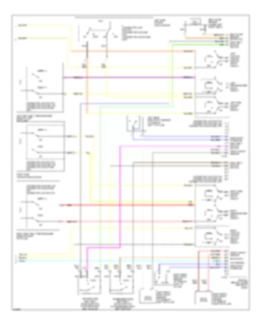
Supplemental Restraints Wiring Diagram (2 of 3) for Mitsubishi Galant SE 2010
List of elements for Supplemental Restraints Wiring Diagram (2 of 3) for Mitsubishi Galant SE 2010:
- (behind right side of dash) passenger's side air bag module squib
- (connector coupled: on) (connector uncoupled: off) connector lock switch
- (connector coupled: on) connector uncoupled: off) connector lock switch
- (in steering wheel) driver's side air bag module squib
- (top of left "c" pillar) left curtain air bag module squib
- (top of right "c" pillar) right curtain air bag module squib
- C-11
- C-29
- C-307
- Clock spring (in steering column)
- G2 (behind center of dash)
- Left front impact sensor (left front of engine compt)
- Left occupant classification sensor (under left side of front passenger's seat)
- Nca
- Occupant classification ecu (under front passenger's seat)
- Off
- Right front impact sensor (right front of engine compt)
- Right occupant classification sensor (under right side of front passenger's seat)
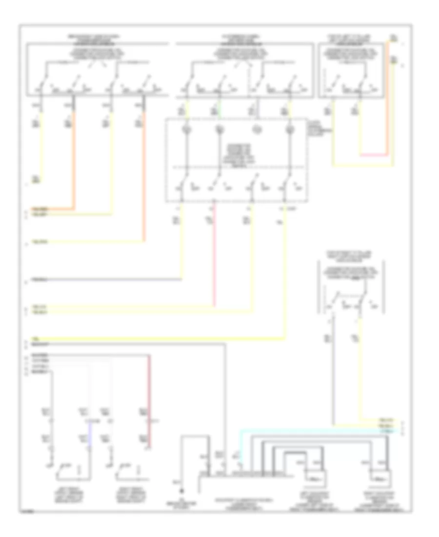
Supplemental Restraints Wiring Diagram (3 of 3) for Mitsubishi Galant SE 2010
List of elements for Supplemental Restraints Wiring Diagram (3 of 3) for Mitsubishi Galant SE 2010:
- (connector coupled: on) (connector uncoupled: off) connector lock switch
- Buckle sw
- C-120
- C-122
- Connector lock switch (connector coupled: on) (connector uncoupled: off)
- Driver's side seat belt buckle switch (in driver's seat belt buckle)
- Front impact sensor
- Hall ic
- Left curtain air bag module drive circuit
- Left front side impact sensor (at base of left "b" pillar)
- Left pretensioner drive circuit
- Left rear side impact sensor (at base of left "c" pillar)
- Left seat belt pretensioner (base of left "b" pillar)
- Left side air bag drive circuit
- Left side air bag module squib
- Nca
- Occ sensor
- Off
- Passenger's side seat belt buckle switch (in passenger's seat belt buckle)
- Red
- Right curtain air bag module drive circuit
- Right front side impact sensor (at base of right "b" pillar)
- Right pretensioner drive circuit
- Right rear side impact sensor (at base of right "c" pillar)
- Right seat belt pretensioner (base of right "b" pillar)
- Right side air bag drive circuit
- Right side air bag module squib
- Seat belt buckle switch
- Seat slide sensor (under left front seat)
- Seat slide sensor detection
- Side impact interface
- Solid state
- Srs ecu (behind lower center of dash)