
SUPPLEMENTAL RESTRAINTS
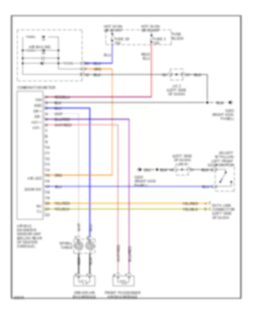
Supplemental Restraint Wiring Diagram for Nissan Quest XE 1997
List of elements for Supplemental Restraint Wiring Diagram for Nissan Quest XE 1997:
AIR CONDITIONINGBODY COMPUTERANTI-THEFTCOMPUTER DATA LINESANTI-LOCK BRAKESCRUISE CONTROLCOOLING FANEXTERIOR LIGHTSENGINE PERFORMANCEDEFOGGERSHEADLIGHTSGROUND DISTRIBUTIONHORNPOWER ANTENNAPOWER DISTRIBUTIONPOWER DOOR LOCKSINTERIOR LIGHTSINSTRUMENT CLUSTERPOWER TOP/SUNROOFPOWER MIRRORSPOWER SEATSRADIOSHIFT INTERLOCKSSUPPLEMENTAL RESTRAINTSTRANSMISSIONPOWER WINDOWSWARNING SYSTEMSSTARTING/CHARGINGWIPER/WASHER