CRUISE CONTROL
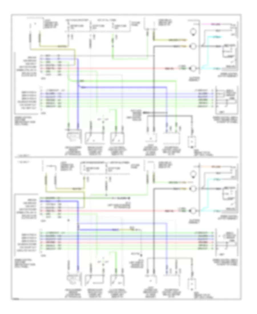
Cruise Control Wiring Diagram for Ford Escort 1996
List of elements for Cruise Control Wiring Diagram for Ford Escort 1996:
- * 1.8l only *
- * 1.9l only *
- A/t
- Anti-lock brakes system (abs control module)
- Boo sw in or clutch sw in
- Brake on/off (boo) switch (under left side of i/p)
- C204
- C210
- C212
- C227
- C234
- C235
- C240
- Clutch pedal position switch (under left side of i/p)
- Coast
- G112 (left side of engine, on transaxle)
- G200 (behind top of left cowl panel)
- Ground
- Horn fuse 20a
- Horn relay (behind left side of i/p)
- Hot at all times
- Hot in run or start
- I/p fuse panel
- Ignition power
- Joint connector (behind left side of i/p)
- Joint connector (behind right i/p, near grommet)
- M/t
- Meter fuse 15a
- Modulte vac out
- Off
- Powertrain control module (below center of i/p)
- Resume
- Servo pos in
- Servo position sensor
- Set/accel
- Slip ring assembly
- Solenoid power
- Speed control amplifier (behind right side cowl panel)
- Speed control servo (right fender apron, in front of wheel)
- Speed control switch assembly
- Speed ctrl sw in
- Stop fuse 20a
- Tan
- Vac
- Vac on/off out
- Vac vent out
- Vehicle speed sensor (lower rear of transaxle)
- Vent
- Vss ground
- Vss input
 Čeština
 Dansk
Dansk Deutsch
 Ελληνικά
 English
 English
 Español
 Suomi
Suomi Français
 Français
 עברית
עברית Hrvatski
 Magyar
 Italiano
 日本語
日本語 한국어
한국어 Nederlands
 Polski
 Português
 Português
 Română
 Русский
 Slovenčina
 Slovenščina
 Türkçe
 中文 (中国)
 Svenska