CRUISE CONTROL
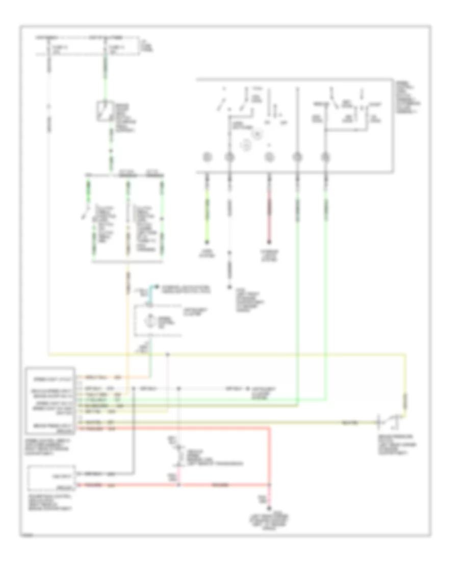
Cruise Control Wiring Diagram for Ford Explorer 1995
List of elements for Cruise Control Wiring Diagram for Ford Explorer 1995:
- (left rear corner of engine compart- ment, at fender apron)
- 10a
- 15a
- A/t w/ console
- A/t w/o console
- Accel
- Brake on/off (boo) switch (on brake pedal support)
- Brake on/off sw in
- Brake press input
- Brake pressure switch (left rear corner of engine compartment)
- Clutch pedal position (cpp) switch (on clutch pedal arm)
- Clutch pedal position (cpp) switch jumper (left side of i/p, taped to main harness)
- Coast
- Fuse 10
- Fuse 13
- G100 (left front of engine compartment, at fender apron)
- G104
- Ground
- Horn switches
- Horn system
- Hot at all times
- Hot in run
- I/p fuse panel
- Ignition
- Instrument cluster
- Instrument cluster system
- Interior lights system
- Interior lights system (headlamp switch, pin 8)
- M/t
- Nca
- Off
- Ohms
- Powertrain control module (pcm) (right rear of engine compartment)
- Resume
- Set/
- Speed cont lp out
- Speed cont sw gnd
- Speed cont sw in
- Speed control ind
- Speed control servo/ amplifier assembly (right rear of engine compartment)
- Speed control/ horn switch assembly (in steering column assembly)
- Vehicle speed input
- Vehicle speed sensor (vss) (left rear of transmission)
- Vss input
 Čeština
 Dansk
Dansk Deutsch
 Ελληνικά
 English
 English
 Español
 Suomi
Suomi Français
 Français
 עברית
עברית Hrvatski
 Magyar
 Italiano
 日本語
日本語 한국어
한국어 Nederlands
 Polski
 Português
 Português
 Română
 Русский
 Slovenčina
 Slovenščina
 Türkçe
 中文 (中国)
 Svenska