
 Čeština
 Dansk
Dansk Deutsch
 Ελληνικά
 English
 English
 Español
 Suomi
Suomi Français
 Français
 עברית
עברית Hrvatski
 Magyar
 Italiano
 日本語
日本語 한국어
한국어 Nederlands
 Polski
 Português
 Português
 Română
 Русский
 Slovenčina
 Slovenščina
 Türkçe
 中文 (中国)

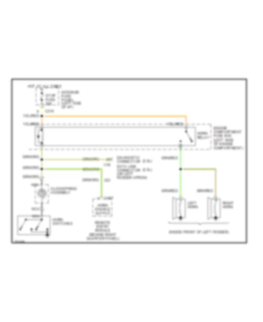
HORN
Horn Wiring Diagram for Ford Probe SE 1996
List of elements for Horn Wiring Diagram for Ford Probe SE 1996:

AIR CONDITIONINGANTI-LOCK BRAKESBODY COMPUTERCOMPUTER DATA LINESCOOLING FANDEFOGGERSEXTERIOR LIGHTSCRUISE CONTROLHEADLIGHTSHORNGROUND DISTRIBUTIONPOWER WINDOWSINSTRUMENT CLUSTERRADIOSHIFT INTERLOCKSINTERIOR LIGHTSPOWER DISTRIBUTIONPOWER MIRRORSPOWER SEATSPOWER DOOR LOCKSENGINE PERFORMANCESTARTING/CHARGINGSUPPLEMENTAL RESTRAINTSPOWER TOP/SUNROOFWARNING SYSTEMSTRANSMISSIONWIPER/WASHER