SHIFT INTERLOCK
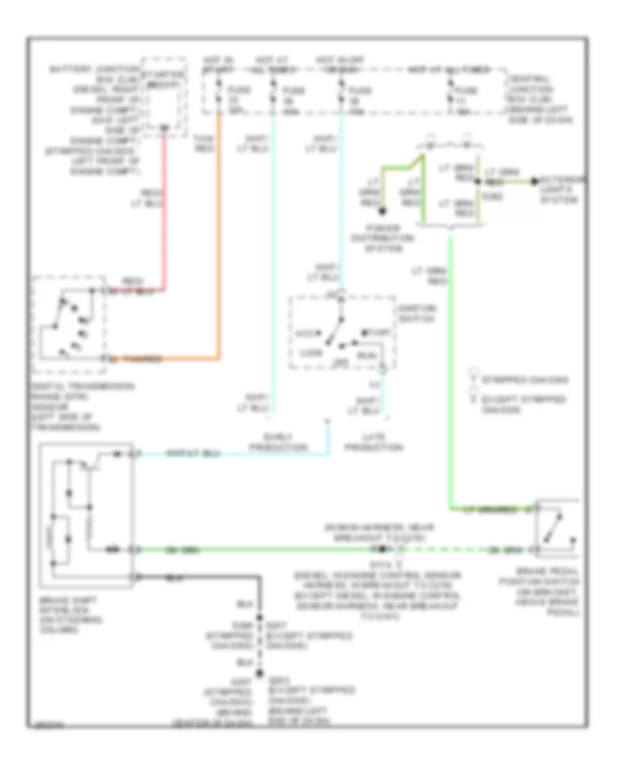
Shift Interlock Wiring Diagram for Ford Econoline E250 2008
List of elements for Shift Interlock Wiring Diagram for Ford Econoline E250 2008:
- (in main harness, near breakout to c219) s220
- Acc
- Battery junction box (cjb) (diesel: right front of engine compt) (gas: left side of engine compt) (stripped chassis : left front of engine compt)
- Brake pedal position switch (on bracket, above brake pedal)
- Brake shift interlock (on steering column)
- Central junction box (cjb) (behind left side of dash)
- Digital transmission range (dtr) sensor (left side of transmission)
- Early production
- Except stripped chassis
- Exterior lights system
- Fuse 10a
- Fuse 15a
- G203 (except stripped chassis) (behind left end of dash)
- G207 (stripped chassis) (behind center of dash)
- Hot at all times
- Hot in off or run
- Hot in start
- Ignition switch
- Late production
- Lock
- Off
- P r
- Power distribution system
- Run
- S174 (diesel: in engine control sensor harness, in breakout to c219) (except diesel: in engine control sensor harness, near breakout to g101)
- S207 (except stripped chassis)
- S282
- S286 (stripped chassis)
- Start
- Starter relay
- Stripped chassis
- Tan/ red
- Tan/red
 Čeština
 Dansk
Dansk Deutsch
 Ελληνικά
 English
 English
 Español
 Suomi
Suomi Français
 Français
 עברית
עברית Hrvatski
 Magyar
 Italiano
 日本語
日本語 한국어
한국어 Nederlands
 Polski
 Português
 Português
 Română
 Русский
 Slovenčina
 Slovenščina
 Türkçe
 中文 (中国)
 Svenska