AIR CONDITIONING
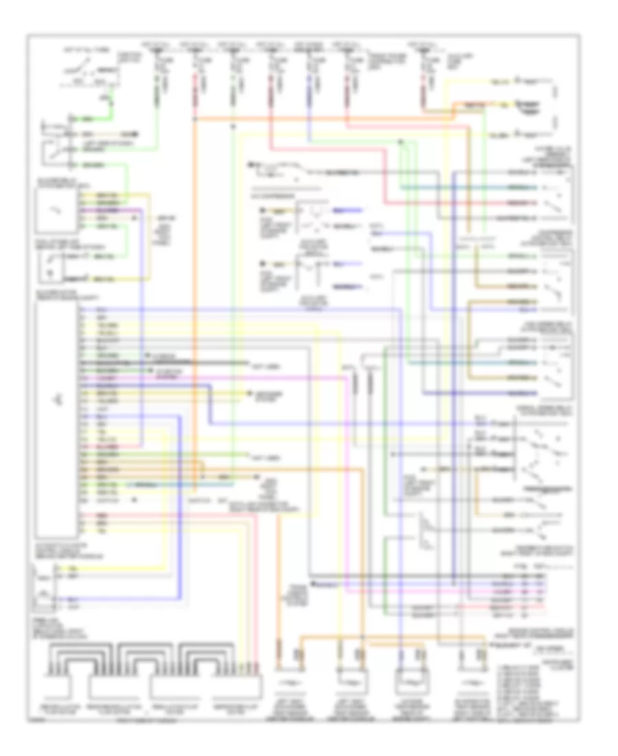
Air Conditioning Wiring Diagrams for BMW 318is 1996
List of elements for Air Conditioning Wiring Diagrams for BMW 318is 1996:
- (left side of dash)
- (not used)
- (right side of plenum)
- 1) below 21 bar
- 2) above 30 bar 3) above 2.6 bar 4) below 1.5 bar
- 4- cyl
- 4-cyl
- 5) above 18 bar 6) below 15 bar 7) 4cyl: above 88 deg c 6cyl: above 99 deg c 8) 4cyl: above 88 deg c 6cyl: above 91 deg c
- 6- cyl
- 6-cyl
- A/c compressor
- Acc
- Automatic climate control module (behind center console)
- Auxiliary fan motor (4-cyl)
- Auxiliary fan motor (6-cyl)
- Auxiliary fuse box
- Blower motor (rear of engine compt)
- Blower relay (in power dist box)
- Compressor control relay (in power dist box)
- Data link connector (right rear of eng compt)
- Defogger system
- Defroster flap motor
- Engine control module (right rear of engine compt)
- Evaporator temp sensor (right side of left footwell)
- Final stage unit (behind left side of dash)
- Fresh air flap motor (below dash, right of steering column)
- Front power distribution box
- Fuse 30a
- Fuse 40a
- Fuse 5a
- Fuse 7.5a
- G100 (left front of engine compt)
- G202
- G203 (right kick panel)
- High speed relay (in power dist box)
- Hot at all times
- Hot in run and start
- Ignition switch
- Instrument cluster
- Interior lights system
- Left heat exchanger temp sensor (center console)
- Lock
- Nca
- Normal speed relay (in power dist box)
- Outside temp sensor (rear of engine compt)
- Pressure switch
- Rear recirculation flap motor
- Recirculation flap motor
- Red
- Regulation flap motor
- Run
- Start
- Starting system
- Temperature switch (right front of eng compt)
- Trans- mission controls system
- Veh speed
- Water valve assembly (left rear side of engine compt)
- X10016
- X10017
- X10018
- X1588
 Čeština
 Dansk
Dansk Deutsch
 Ελληνικά
 English
 English
 Español
 Suomi
Suomi Français
 Français
 עברית
עברית Hrvatski
 Magyar
 Italiano
 日本語
日本語 한국어
한국어 Nederlands
 Polski
 Português
 Português
 Română
 Русский
 Slovenčina
 Slovenščina
 Türkçe
 中文 (中国)
 Svenska