AIR CONDITIONING
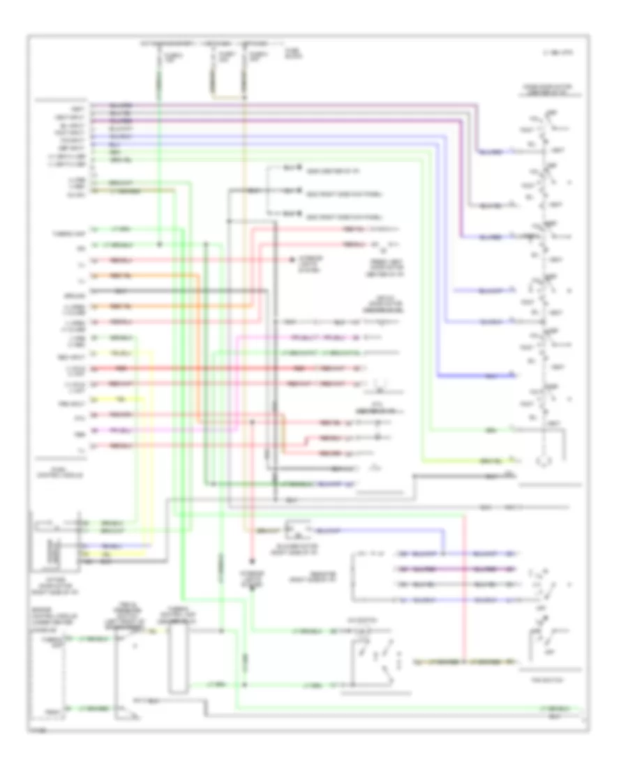
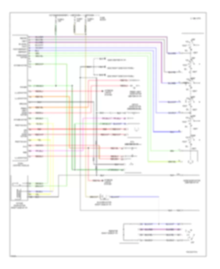
A/C Wiring Diagram, Auto A/C (1 of 2) for Nissan Altima GLE 1995
 https://portal-diagnostov.com/license.html
Automotive Electricians Portal FZCO
Automotive Electricians Portal FZCO
https://portal-diagnostov.com/license.html
https://portal-diagnostov.com/license.html
Automotive Electricians Portal FZCO
Automotive Electricians Portal FZCO
List of elements for A/C Wiring Diagram, Auto A/C (1 of 2) for Nissan Altima GLE 1995:
- (center g206
- (center of i/p)
- (left side
- (right de-
- (right rear of engine)
- (right side g203
- (right side of i/p)
- +5v
- 1994 vftc c
- A/mix actr
- A/mix pbr
- Air mix door motor
- Amb sen
- Ambient sensor (center front
- Auto amp
- B/l
- Bat
- Blower hi relay (right side of i/p)
- Blower motor
- Blwr rly
- Def
- Engine control module (below center console)
- F/d
- Fan control amp
- Fan f/b
- Fan gate
- Fascia)
- Foot
- Fresh vent door motor
- Froster grille)
- Fuse 10a
- Fuse 20a
- Fuse 26 10a
- Fuse block
- Fv actr
- Gnd
- Hot at all times
- Hot in on
- I/p)
- Ign
- Ill
- In vehicle sensor
- Incar sens
- Intake 20% fre/fre
- Intake actr
- Intake door motor
- Intake fre/rec
- Intake rec 20% fre
- Interior lights system
- Kick panel)
- Mode actr
- Mode def b/l foot
- Mode door motor (center of i/p)
- Mode f/d def
- Mode foot f/d vent
- Mood vent
- Of i/p)
- Or start
- Pnk
- Position switch
- Psdw
- Red
- Sens gnd
- Sun sensor
- Sunload sensor
- Thermal transmitter
- Thermo amp
- Thermo amp
- Thermo control amp
- Triple pressure switch (left front of engine compt)
- Vent
- W/t sens
A/C Wiring Diagram, Auto A/C (2 of 2) for Nissan Altima GLE 1995
List of elements for A/C Wiring Diagram, Auto A/C (2 of 2) for Nissan Altima GLE 1995:
- (left front g100
- (right g101
- 1994 vftc c
- A/c compressor clutch
- A/c relay (relay box 1, right front of engine compt)
- Acrly
- Cooling fan motor 1
- Cooling fan motor 2
- Cooling fan relay 1 (relay box 2, left front of engine compt)
- Cooling fan relay 2 (relay box 1, right front of engine compt)
- Cooling fan relay 3 (relay box 1, right front of engine compt)
- Engine control module (under center console)
- Fender)
- Front fender)
- Fuse 10a
- Fuse 4 10a
- Fuse box
- Fusible link f 30a
- Fusible link h 30a
- Fusible link box
- Fusible link e 75a
- Hot at all times
- Hot in on and start
- Idle air control valve (right rear of engine)
- J/c
- J/c 1
- J/c 2
- Nca
- Rfrh
- Rfrl
- Thermal protector
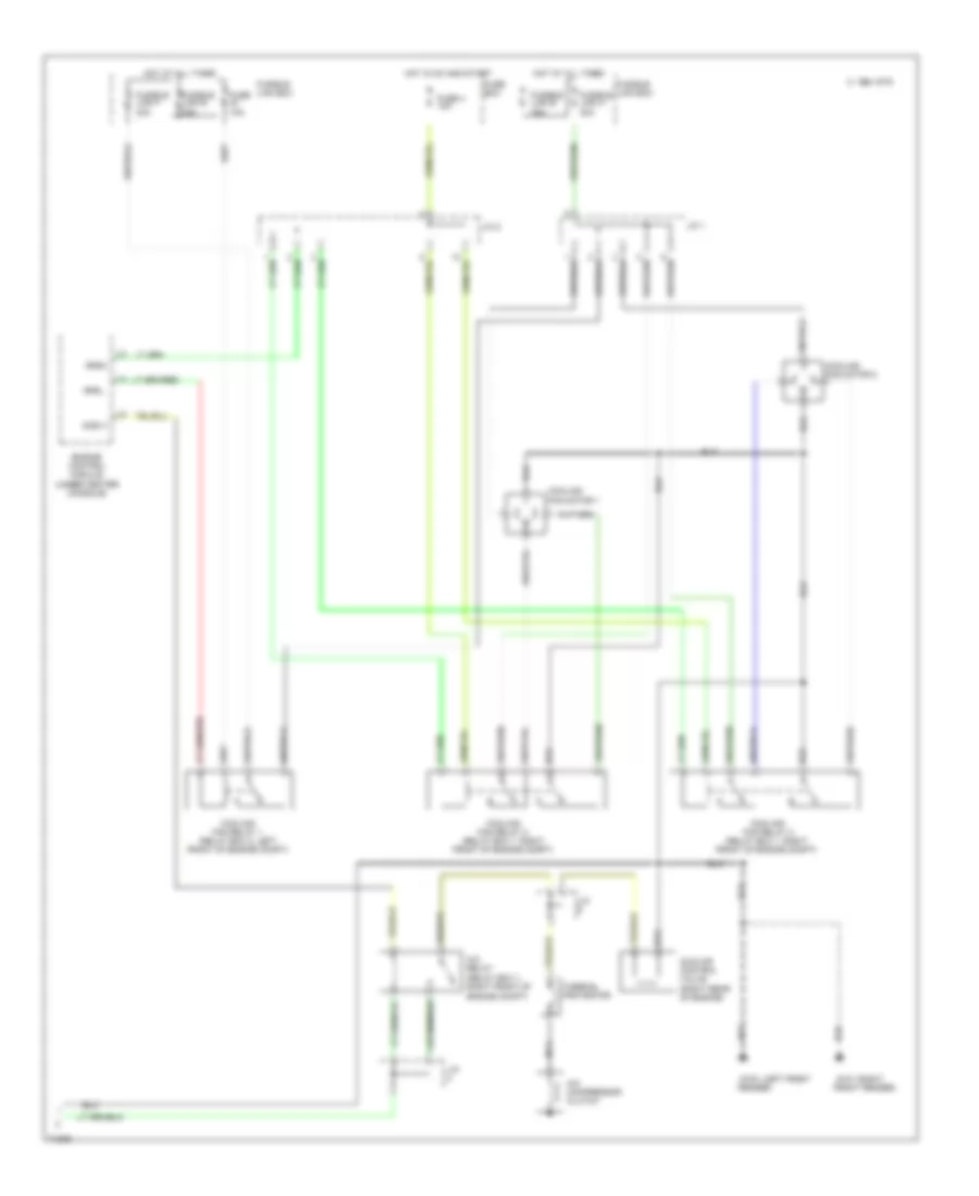
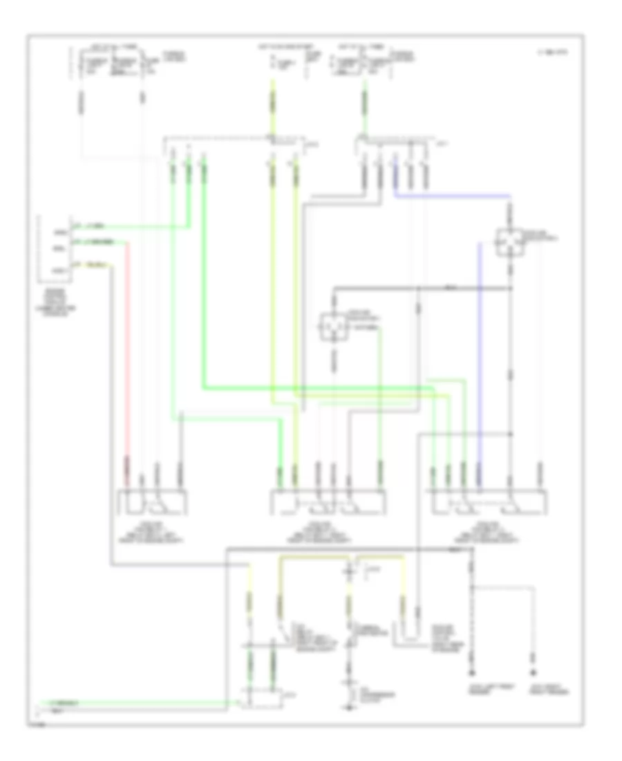
A/C Wiring Diagram, Manual A/C (1 of 2) for Nissan Altima GLE 1995
List of elements for A/C Wiring Diagram, Manual A/C (1 of 2) for Nissan Altima GLE 1995:
- (+) cold (-) hot
- (+) fre (-) rec
- (+) open (-) close
- (+) vent/(-) def
- (-) cold (+) hot
- (-) fre (+) rec
- (-) open (+) close
- (-) vent/(+) def
- (center of i/p)
- (center of i/p) g206
- (right side kick panel) g203
- (right side of i/p)
- 1994 vftc c
- A/c sw
- A/c switch
- Air mix door motor
- B/l
- B/l input
- Blower motor
- Console)
- Def
- Def input
- Engine control module (under center
- F/d
- F/d input
- Fan switch
- Foot
- Foot input
- Fre input
- Fresh vent door motor
- Fuse 6 10a
- Fuse 7 20a
- Fuse 8 20a
- Fuse block
- Ground
- Hot in on
- Hot in on or start
- Ign
- Ill
- Intake door motor
- Interior lights system
- Mode door motor (center of i/p)
- Off
- Pbr
- Psdw
- Ptc
- Push control module
- Rec input
- Red
- Resistor
- Switch position
- Thermo amp
- Thermo control amp
- Triple pressure switch (left front of engine compt)
- Vent
- Vent input
A/C Wiring Diagram, Manual A/C (2 of 2) for Nissan Altima GLE 1995
List of elements for A/C Wiring Diagram, Manual A/C (2 of 2) for Nissan Altima GLE 1995:
- (left front g100
- (right g101
- 1994 vftc c
- A/c compressor clutch
- A/c relay (relay box 1, right front of engine compt)
- Acrly
- Cooling fan motor 1
- Cooling fan motor 2
- Cooling fan relay 1 (relay box 2, left front of engine compt)
- Cooling fan relay 2 (relay box 1, right front of engine compt)
- Cooling fan relay 3 (relay box 1, right front of engine compt)
- Engine control module (under center console)
- Fender)
- Front fender)
- Fuse 10a
- Fuse 4 10a
- Fuse box
- Fusible link f 30a
- Fusible link h 30a
- Fusible link box
- Fusible link e 75a
- Hot at all times
- Hot in on and start
- Idle air control valve (right rear of engine)
- J/c 1
- J/c 2
- J/c 6
- Nca
- Rfrh
- Rfrl
- Thermal protector
Heater Wiring Diagram for Nissan Altima GLE 1995
List of elements for Heater Wiring Diagram for Nissan Altima GLE 1995:
- (center of i/p)
- (center of i/p) g206
- (right side kick panel) g203
- (right side of i/p)
- 1994 vftc c
- Air mix
- Air mix door motor
- B/l
- Bi-level
- Blower motor
- Def
- Defrost
- Door motor
- F/d
- Fan switch
- Foot
- Foot/defrost
- Fresh vent
- Fresh vent door motor
- Fuse 6 10a
- Fuse 7 20a
- Fuse 8 20a
- Fuse block
- Ground
- Hot in on
- Hot in on or start
- Illumination
- Intake door motor
- Intake motor
- Interior lights system
- Mode door motor
- Mode door motor (center of i/p)
- Off
- Pbr
- Position sw
- Power
- Ptc
- Push control module
- Recirc
- Red
- Resistor
- Switch position
- Vent

 Čeština
 Dansk
Dansk Deutsch
 Ελληνικά
 English
 English
 Español
 Suomi
Suomi Français
 Français
 עברית
עברית Hrvatski
 Magyar
 Italiano
 日本語
日本語 한국어
한국어 Nederlands
 Polski
 Português
 Português
 Română
 Русский
 Slovenčina
 Slovenščina
 Türkçe
 中文 (中国)