AIR CONDITIONING
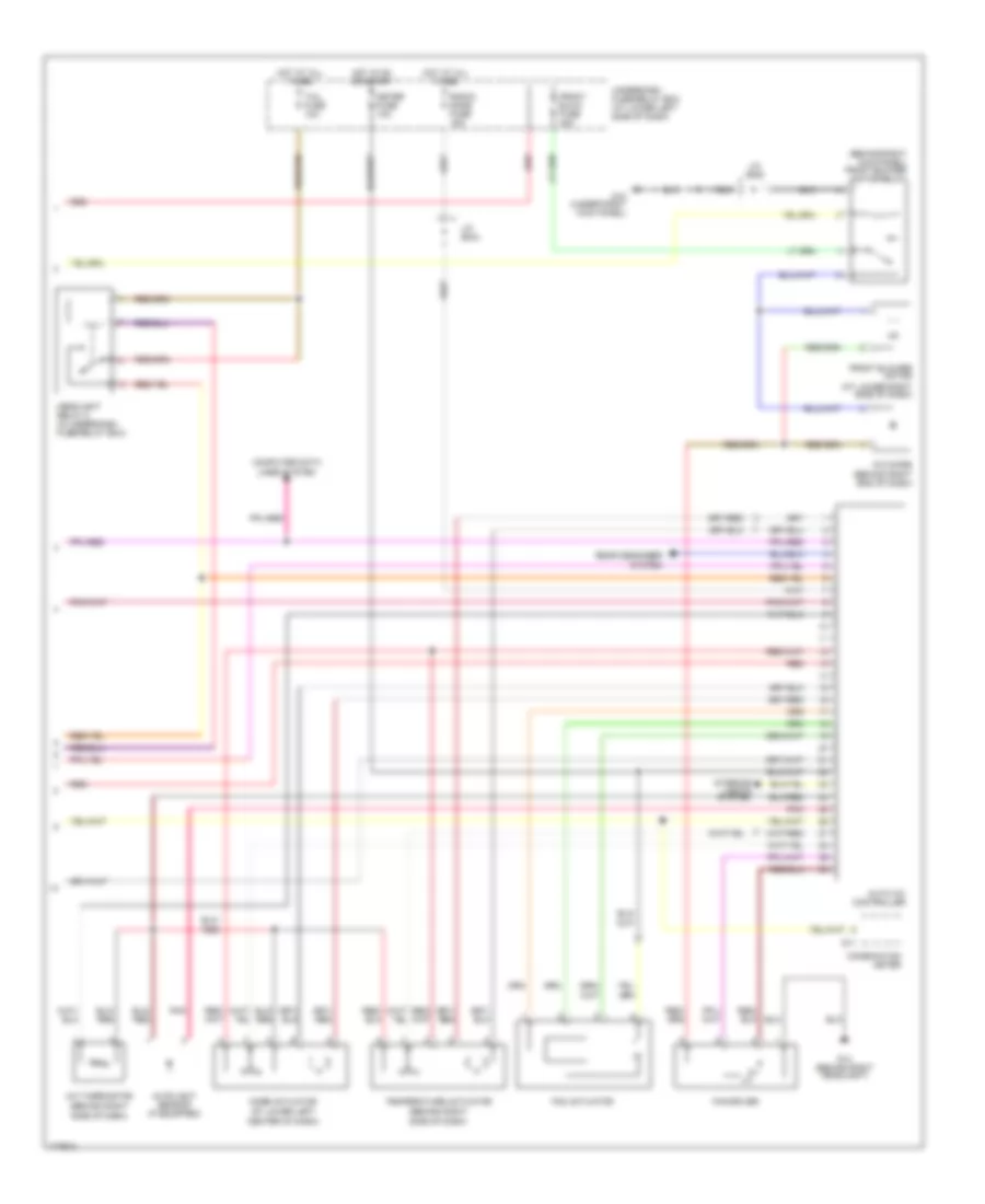
Automatic A/C Wiring Diagram (1 of 2) for Suzuki XL-7 Limited 2003
 https://portal-diagnostov.com/license.html
Automotive Electricians Portal FZCO
Automotive Electricians Portal FZCO
https://portal-diagnostov.com/license.html
https://portal-diagnostov.com/license.html
Automotive Electricians Portal FZCO
Automotive Electricians Portal FZCO
List of elements for Automatic A/C Wiring Diagram (1 of 2) for Suzuki XL-7 Limited 2003:
- A/c compressor
- A/c compressor relay (in underhood fuse/relay box)
- A/c condenser fan high relay 1 (in underhood fuse/relay box)
- A/c condenser fan high relay 2 (in underhood fuse/relay box)
- A/c fuse 25a
- Body control module (behind center of dash)
- C51-3
- Condenser fan motor
- Condenser fan relay (in underhood fuse/relay box)
- E120
- E121
- E61
- Ecm/pcm (behind glove box)
- Ect sensor (at top left of engine)
- G10 (under right kick panel)
- G53
- G54
- G55
- G57
- G7 (behind left headlight)
- G8 (behind right headlight)
- Heater fuse 15a
- Hot at all times
- Hot in on
- Htr fuse 60a
- J/c (e45)
- Main fuse box (in underhood fuse/relay box)
- Outdoor sensor (at right front of engine compartment)
- Pnk
- Red
- Triple switch (at right front of engine compartment)
- Underdash fuse/relay box (at lower left side of dash)
Automatic A/C Wiring Diagram (2 of 2) for Suzuki XL-7 Limited 2003
List of elements for Automatic A/C Wiring Diagram (2 of 2) for Suzuki XL-7 Limited 2003:
- (at lower left
- (at lower right side of dash)
- (behind right
- (behind right kick panel) front blower motor relay
- A/c diode (behind right end of dash)
- A/c thermistor
- Auto a/c controller
- Autolight sensor (if equipped)
- Center of dash)
- Combination meter
- Computer data lines system
- Fan actuator
- Fan driver
- Front blow fuse 40a
- Front blower motor
- G10 (under right kick panel)
- G11
- G14 (behind right headlight)
- Headlight relay 2 (in underdash fuse/relay box)
- Hot at all times
- Hot in on or start
- Interior lights system
- J/c (e44)
- J/c (e45)
- Meter fuse 10a
- Mode actuator
- Pnk
- Radio/ dome fuse 15a
- Rear degogger system
- Red
- Side of dash)
- Tail fuse 10a
- Temperature actuator
- Underdash fuse/relay box (at lower left side of dash)
Rear A/C Wiring Diagram for Suzuki XL-7 Limited 2003
List of elements for Rear A/C Wiring Diagram for Suzuki XL-7 Limited 2003:
- Body control module (behind center of dash)
- G54
- G55
- G57
- G9 (under left kick panel)
- Headlight relay 2 (in underdash fuse/relay box)
- Heater fuse 15a
- Hot at all times
- Hot in on
- Illumination j/c (e44)
- J/c (e45)
- J/c (g29)
- Off
- Rear blower fan resistor (at left rear of vehicle)
- Rear blower fuse 20a
- Rear blower motor (at left rear of vehicle)
- Rear blower motor relay (in underdash fuse/relay box)
- Rear fan motor switch
- Rear fan switch
- Tail fuse 10a
- Underdash fuse/relay box (at lower left side of dash)

 Čeština
 Dansk
Dansk Deutsch
 Ελληνικά
 English
 English
 Español
 Suomi
Suomi Français
 Français
 עברית
עברית Hrvatski
 Magyar
 Italiano
 日本語
日本語 한국어
한국어 Nederlands
 Polski
 Português
 Português
 Română
 Русский
 Slovenčina
 Slovenščina
 Türkçe
 中文 (中国)