ANTI-LOCK BRAKES
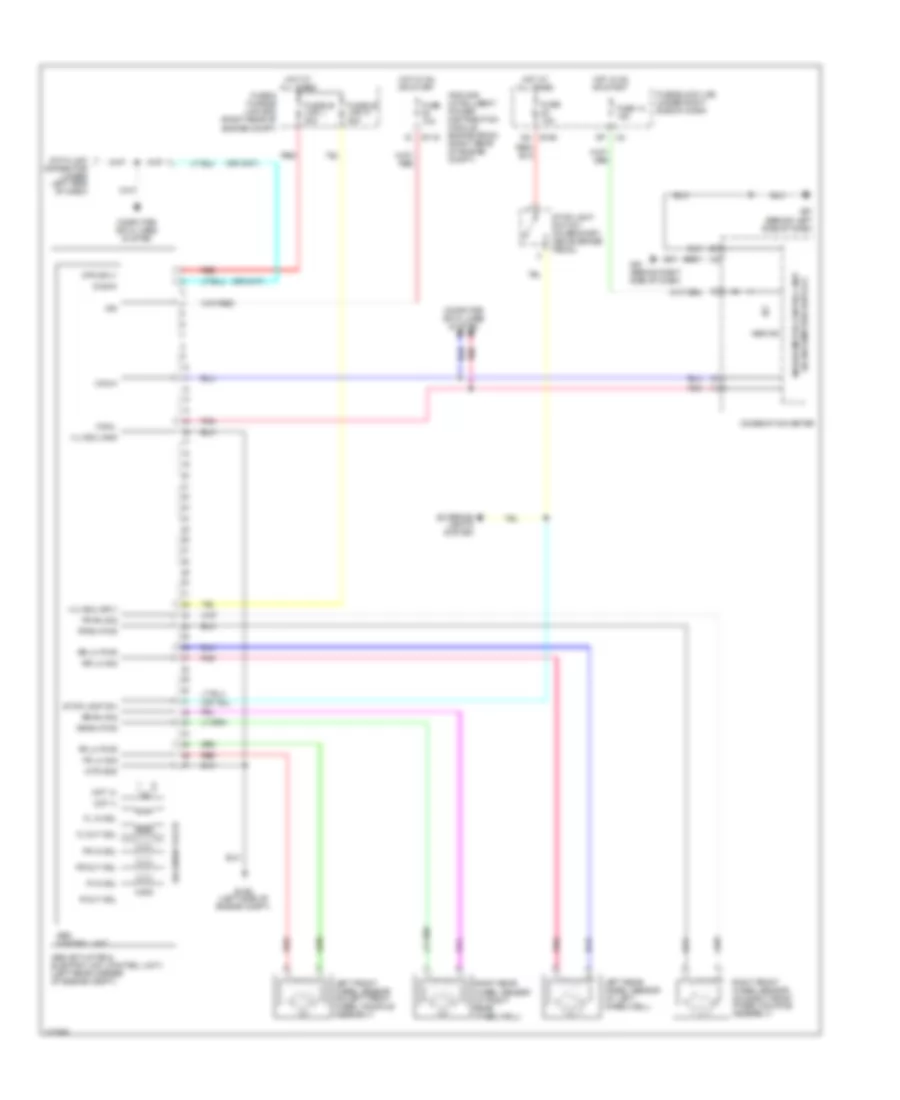
Anti-lock Brakes Wiring Diagram for Nissan Frontier SE 2010
List of elements for Anti-lock Brakes Wiring Diagram for Nissan Frontier SE 2010:
- (w/ information display) unified meter control unit
- Abs actuator & electric unit (control unit) (left rear corner of engine compt)
- Abs control unit
- Abs ind
- Can-h
- Can-l
- Combination meter
- Computer data lines system
- Data link connector (under left side of dash)
- Diag-k
- E119
- E126 (left side of engine compt)
- E160
- Exterior lights system
- Fl in sol
- Fl out sol
- Fr in sol
- Fr lh pwr
- Fr lh sig
- Fr out sol
- Fr rh pwr
- Fr rh sig
- Fuse & fusible link box (right rear of engine compt)
- Fuse 10a
- Fuse 14 10a
- Fuse block (j/b) (under right side of dash)
- Fusible link l 30a
- Fusible link n 40a
- Hot at all times
- Hot in on or start
- Ign
- Ipdm e/r (intelligent power distribution module engine room) (right rear of engine compt)
- Left front wheel sensor (on left front wheel knuckle assembly)
- Left rear wheel sensor (at left wheelwell)
- M57 (behind left side of dash)
- M61 (behind right side of dash)
- Mot (+)
- Mot (-)
- Mtr gnd
- Mtr sply
- Pnk
- R in sol
- R out sol
- Red
- Right front wheel sensor (on right front wheel knuckle assembly)
- Right rear wheel sensor (at right rear wheelwell)
- Rr lh pwr
- Rr lh sig
- Rr rh pwr
- Rr rh sig
- Solenoid valve
- Stop lamp sw
- Stop light switch (on bracket, above brake pedal)
- Vlv ecu gnd
- Vlv ecu sply
 Čeština
 Dansk
Dansk Deutsch
 Ελληνικά
 English
 English
 Español
 Suomi
Suomi Français
 Français
 עברית
עברית Hrvatski
 Magyar
 Italiano
 日本語
日本語 한국어
한국어 Nederlands
 Polski
 Português
 Português
 Română
 Русский
 Slovenčina
 Slovenščina
 Türkçe
 中文 (中国)
 Svenska