ANTI-LOCK BRAKES
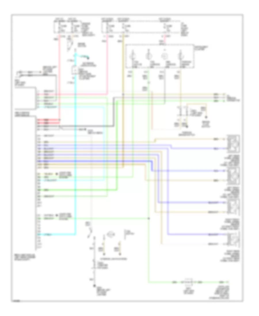
Anti-lock Brakes Wiring Diagram for Suzuki Verona LX 2004
List of elements for Anti-lock Brakes Wiring Diagram for Suzuki Verona LX 2004:
- (behind left of cigar lighter) g202
- A10
- A11
- A13
- A14
- A16
- Abs warning ind
- Abs warning lamp module
- B10
- B11
- Brake fluid switch
- Brake switch
- C10
- C102
- C11
- C201
- C202
- Computer data lines system
- Data link connector (below left side of dash, right of steering column)
- Ebcm (abs module) (left rear corner of eng compt)
- Engine fuse block (left front of eng compt)
- Exterior lamps system
- Fuse 10a
- Fuse 15a
- Fuse 20a
- Fuse 60a
- G105 (below ebcm)
- G202 (behind left of cigar lighter)
- Hot at all times
- Hot in run & start
- I/p fuse block (left end of dash)
- Instrument cluster
- Interior lights system
- Left front wheel speed sensor (at left front wheel hub assy)
- Left rear wheel speed sensor (at left rear wheel hub assy)
- Oil feeding connector
- Parking brake ind
- Parking brake switch
- Pnk
- Pnk b14
- Red
- Right front wheel speed sensor (at right front wheel hub assy)
- Right rear wheel speed sensor (at right rear wheel hub assy)
- S201 (left end of dash)
- S203 (center of dash)
- S301 (behind right side of instrument cluster)
- Tcs active ind
- Tcs switch
- Tcs warning ind
 Čeština
 Dansk
Dansk Deutsch
 Ελληνικά
 English
 English
 Español
 Suomi
Suomi Français
 Français
 עברית
עברית Hrvatski
 Magyar
 Italiano
 日本語
日本語 한국어
한국어 Nederlands
 Polski
 Português
 Português
 Română
 Русский
 Slovenčina
 Slovenščina
 Türkçe
 中文 (中国)
 Svenska