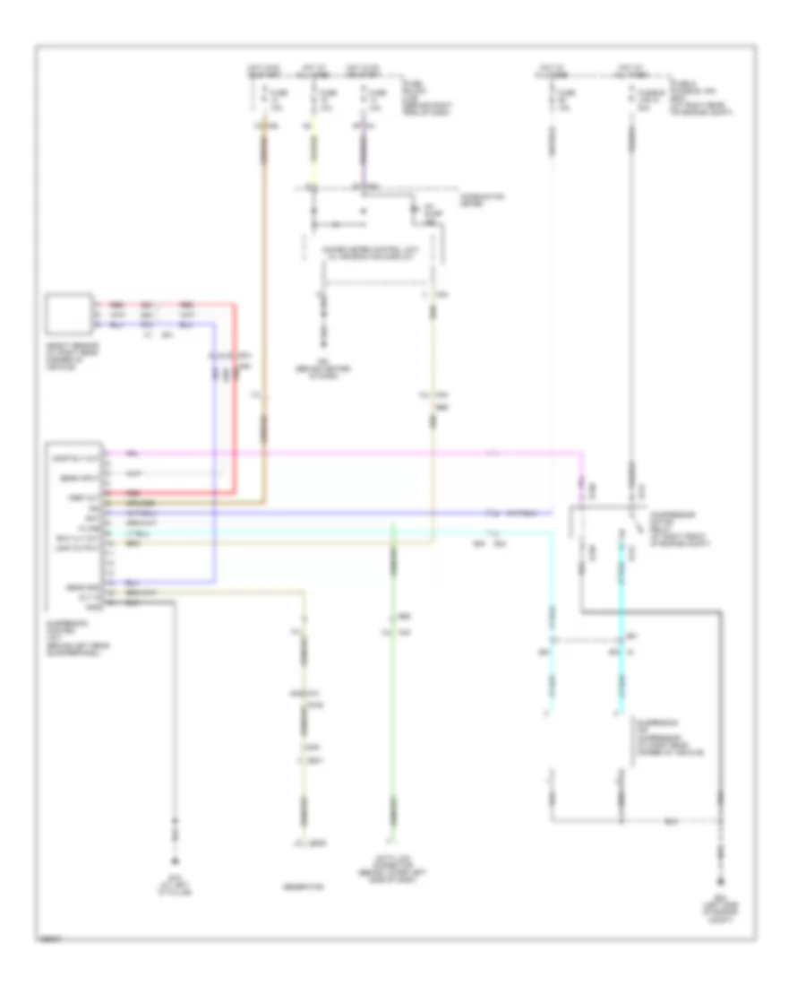
ELECTRONIC SUSPENSION
Electronic Suspension Wiring Diagram for Nissan Armada SL 2014
List of elements for Electronic Suspension Wiring Diagram for Nissan Armada SL 2014:
- 12j m40
- 13j
- 14j m40
- 17j
- 1q m39
- 25c
- 27c
- 28c
- 29c
- 44g m31
- 48c c1
- 5p m4
- Alt in
- B19 (at left "d" pillar)
- B40
- B40 red
- B69
- Bat
- Ck susp ind
- Combination meter
- Comp rly out
- Compressor motor relay (at right front of engine compt)
- Data link connector (behind lower left side of dash)
- E130
- E131
- E201
- E205
- E24 (left side of engine compt)
- E34
- E40
- E41
- Exh vlv out
- Fuse & fusible link box (at right rear of engine compt)
- Fuse 10a
- Fuse block (j/b) (behind right end of dash)
- Fusible link g 30a
- Generator
- Gnd
- Height sensor (at right rear corner of vehicle)
- Hot at all times
- Hot in on or start
- Ign
- K-line
- Lamp output
- M24
- M61 (behind center of dash)
- Red
- Sens gnd
- Sens input
- Suspension air compressor (at right rear corner of vehicle)
- Suspension control unit (behind left rear quarterpanel)
- Unified meter control unit (w/ information display)
- Vref out
 Čeština
 Dansk
Dansk Deutsch
 Ελληνικά
 English
 English
 Español
 Suomi
Suomi Français
 Français
 עברית
עברית Hrvatski
 Magyar
 Italiano
 日本語
日本語 한국어
한국어 Nederlands
 Polski
 Português
 Português
 Română
 Русский
 Slovenčina
 Slovenščina
 Türkçe
 中文 (中国)
 Svenska