SHIFT INTERLOCK
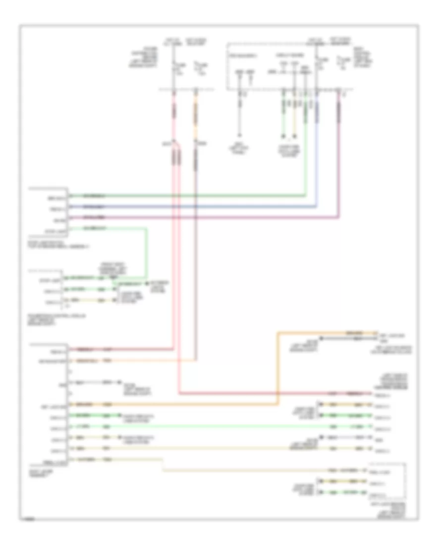
Shift Interlock Wiring Diagram for Fiat 500 Abarth 2013
List of elements for Shift Interlock Wiring Diagram for Fiat 500 Abarth 2013:
- (front body harness, left side of dash) s009
- (left side of transmission) transmission control module
- A107
- Anti-lock brakes module (left rear of engine compt)
- B134
- Body control module (left end of dash)
- Brk sig 2
- Can c (+)
- Can c (-)
- Circuit board
- Computer data lines system
- D64
- D65
- Exterior lights system
- F202
- Fsd b (+)
- Fuse 10a
- Fuse 5a
- Fuse 7.5a
- G010b (left rear of engine compt)
- G021 (left kick panel)
- Gnd
- Hot at all times
- Hot in run or start
- Ign rs
- Ign run/start
- K320
- Key lock sig
- Key lock solenoid (on steering column)
- L56
- Pdc bus bar 3
- Pndl hi sw
- Power distribution center (left rear of engine compt)
- Powertrain control module (left rear of engine compt)
- Prndl hi sw
- S019
- S056
- Shift lever assembly
- Stop lamp
- Stop lamp switch (top of brake pedal assembly)
- T824
- Z910
 Čeština
 Dansk
Dansk Deutsch
 Ελληνικά
 English
 English
 Español
 Suomi
Suomi Français
 Français
 עברית
עברית Hrvatski
 Magyar
 Italiano
 日本語
日本語 한국어
한국어 Nederlands
 Polski
 Português
 Português
 Română
 Русский
 Slovenčina
 Slovenščina
 Türkçe
 中文 (中国)
 Svenska