SUPPLEMENTAL RESTRAINTS
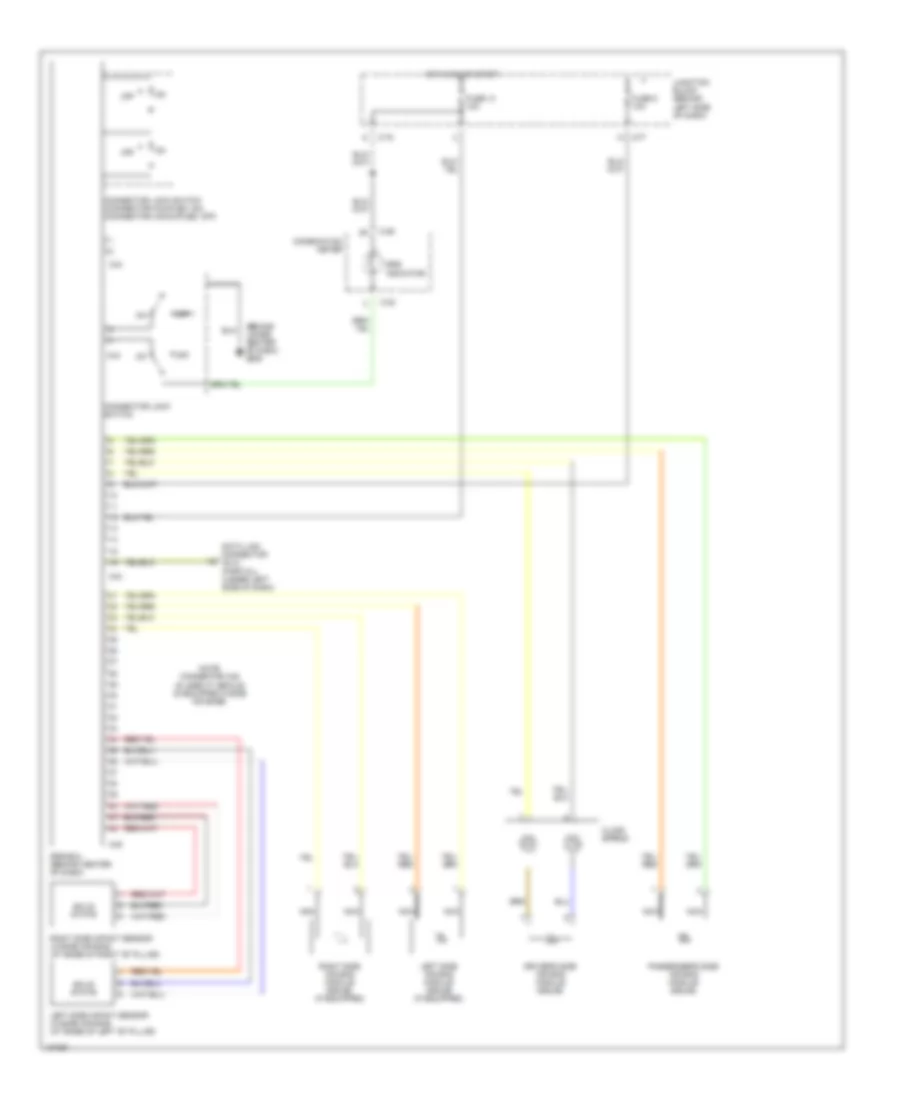
Supplemental Restraint Wiring Diagram for Mitsubishi Galant LS 2000
List of elements for Supplemental Restraint Wiring Diagram for Mitsubishi Galant LS 2000:
- (behind lower center of dash) g206
- C-29
- C-30
- C-77
- C-78
- C44
- C45
- Clock spring
- Combination meter
- Connector lock switch
- Connector lock switch (connector coupled: on) (connector uncoupled: off)
- Data link connector (dlc) (partial) (under left side of dash)
- Driver's side air bag module (squib)
- Fuse 13 10a
- Fuse 5 10a
- Hot in on or start
- Junction block (behind left side of dash)
- Left side air bag module (squib) (if equipped)
- Left side impact sensor (w/side air bag) (at base of left "b" pillar)
- Nca
- Note: connector c45 is used if vehicle is equipped w/side air bags.
- Off
- Passenger's side air bag module (squib)
- Right side air bag module (squib) (if equipped)
- Right side impact sensor (w/side air bag) (at base of right "b" pillar)
- Solid state
- Srs indicator
- Srs-ecu (behind center of dash)
 Čeština
 Dansk
Dansk Deutsch
 Ελληνικά
 English
 English
 Español
 Suomi
Suomi Français
 Français
 עברית
עברית Hrvatski
 Magyar
 Italiano
 日本語
日本語 한국어
한국어 Nederlands
 Polski
 Português
 Português
 Română
 Русский
 Slovenčina
 Slovenščina
 Türkçe
 中文 (中国)
 Svenska