ELECTRONIC MUFFLER
Electronic Muffler Wiring Diagram for Chevrolet Corvette Stingray 2014
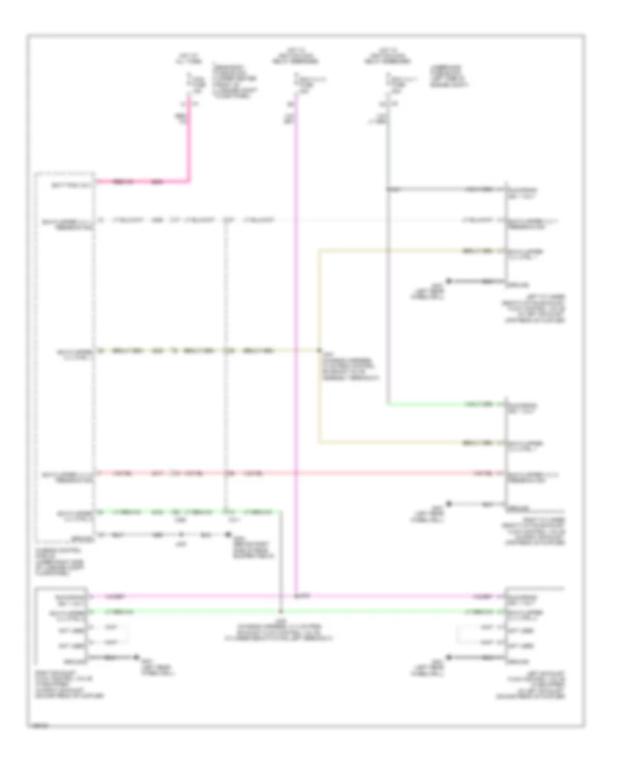
List of elements for Electronic Muffler Wiring Diagram for Chevrolet Corvette Stingray 2014:
- Batt pos volt
- Chassis control module (under right side of luggage compt floor panel)
- Exh flapper vlv 1 feedback sig
- Exh flapper vlv 2 feedback sig
- Exh flapper vlv ctrl 1
- Exh flapper vlv ctrl 2
- Exh vlv 1 fuse 20a
- Exh vlv 2 fuse 20a
- G401 (left rear wheelwell)
- G404 (behind right side of rear bumper fascia)
- Ground
- Hot at all times
- Hot w/ ignition main relay energized
- Iccm fuse 15a
- J341
- J343
- J344 (chassis harness, 10 cm from control solenoid valve assembly breakout)
- J345 (chassis harness, 31.4 cm from exhaust flow control valve, cylinder deactivation left breakout)
- J400
- Left cylinder deactivation exhaust flow control valve (in left exhaust, upstream of muffler)
- Left exhaust flow control valve (if equipped) (in left exhaust, downstream of muffler)
- Not used
- Rear body fuse block (under center front of luggage compt floor panel)
- Right cylinder deactivation exhaust flow control valve (in right exhaust, upstream of muffler)
- Right exhaust flow control valve (if equipped) (in right exhaust, downstream of muffler)
- Run/crank ign 1 volt
- Underhood fuse block (left side of engine compt)
- X311
- X350
- X5 k2
 Čeština
 Dansk
Dansk Deutsch
 Ελληνικά
 English
 English
 Español
 Suomi
Suomi Français
 Français
 עברית
עברית Hrvatski
 Magyar
 Italiano
 日本語
日本語 한국어
한국어 Nederlands
 Polski
 Português
 Português
 Română
 Русский
 Slovenčina
 Slovenščina
 Türkçe
 中文 (中国)
 Svenska