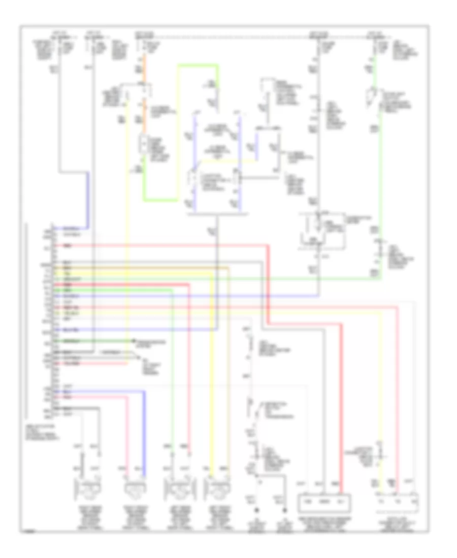
ANTI-LOCK BRAKES
Anti-lock Brakes Wiring Diagram for Toyota Tacoma 2003
List of elements for Anti-lock Brakes Wiring Diagram for Toyota Tacoma 2003:
- +bm
- +bs
- A/t
- Abs 2 fuse 30a
- Abs actuator w/ ecu (on right rear of engine compt)
- Abs deceleration sensor (4wd and pre-runner) (behind dash, left of steering column)
- Abs fuse 60a
- Abs inverter
- Abs warning light ind
- C13
- Combination meter
- D/g
- D16
- D19
- Data link connector (dlc) 3 (below left center of dash)
- Detection switch (on transmission)
- Diode (abs) (behind upper left side of dash)
- Ec (at right front fender)
- Ecu-ig fuse 15a
- Exi
- Exi2
- Exi4
- F12
- Fl+
- Fl-
- Fr+
- Fr-
- Fuse box (on left side of engine compt)
- Gauge fuse 10a
- Ggnd
- Gl1
- Gnd
- Hot at all times
- Hot in on or start
- Ie (at right side of of dash)
- Ig (at left side of of dash)
- Ig1
- J/b 1 (behind dash, left of steering column)
- J/b 3 (center) (behind center of dash)
- J/b 3 (left) (behind dash, above steering column)
- Junction connector 11 (above glove box)
- Junction connector 13 (above glove box)
- Left front abs speed sensor (on inside of left front wheel)
- Left rear abs speed sensor (on inside of left rear wheel)
- M/t
- Pnk
- R/b 2 (on left side of engine compt)
- Rear differential lock ecu (on upper left kick kick panel)
- Red
- Right front abs speed sensor (on inside of right front wheel)
- Right rear abs speed sensor (on inside of right rear wheel)
- Rl+
- Rl-
- Rr+
- Rr-
- Sil
- Stop fuse 10a
- Stoplight switch (on bracket, above brake pedal)
- Stp
- Transmissions system
- Vgs
- W/ rear differential lock
- W/o rear differential lock
 Čeština
 Dansk
Dansk Deutsch
 Ελληνικά
 English
 English
 Español
 Suomi
Suomi Français
 Français
 עברית
עברית Hrvatski
 Magyar
 Italiano
 日本語
日本語 한국어
한국어 Nederlands
 Polski
 Português
 Português
 Română
 Русский
 Slovenčina
 Slovenščina
 Türkçe
 中文 (中国)
 Svenska