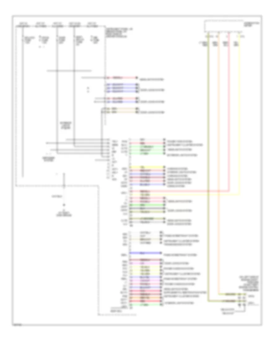
BODY CONTROL MODULES
Body Control Modules Wiring Diagram for Toyota Celica GT 2005
List of elements for Body Control Modules Wiring Diagram for Toyota Celica GT 2005:
- (on left side of engine compt, forward of battery) engine control module (ecm)
- Acc
- Act+
- Act-
- Actd
- Bltw
- Blvl
- Body ecu
- Body ecu-ig fuse 5a
- C12
- C13
- Celica gt
- Celica gts
- Cltb
- Clte
- Clts
- Combination meter
- Dbkl
- Dcty
- Def
- Def fuse 30a
- Defb
- Defogger system
- Door fuse 20a
- Door locks system
- Drl
- Ecu-acc fuse 7.5a
- Exterior lights system
- Fu+
- Fu-
- Fua
- Headlights system
- Horn
- Horns system
- Hot at all times
- Hot in acc or on
- Hot in on or start
- Hrly
- If (at right dash brace)
- Instrument cluster system
- Instrument panel j/b (behind panel on right side of center console)
- Interior lights system
- Ksw
- Lgcy
- Lswd
- Lswp
- Mpx-b fuse 7.5a
- Mpx1
- Mpx2
- P/w
- Passive restraint system
- Pbkl
- Pcty
- Pkb
- Pnk
- Power tops system
- Power windows system
- Prg
- Pws
- Rda
- Red
- Sg1
- Sg2
- Sg3
- Sg4
- Transmissions system
- Trly
- Ul1
- Ul2
- Ul3
- Warning system
 Čeština
 Dansk
Dansk Deutsch
 Ελληνικά
 English
 English
 Español
 Suomi
Suomi Français
 Français
 עברית
עברית Hrvatski
 Magyar
 Italiano
 日本語
日本語 한국어
한국어 Nederlands
 Polski
 Português
 Português
 Română
 Русский
 Slovenčina
 Slovenščina
 Türkçe
 中文 (中国)
 Svenska