TRANSMISSION
2.4L
2.4L, Overdrive Wiring Diagram, 2WD for Toyota Pickup SR5 1995
 https://portal-diagnostov.com/license.html
Automotive Electricians Portal FZCO
Automotive Electricians Portal FZCO
https://portal-diagnostov.com/license.html
https://portal-diagnostov.com/license.html
Automotive Electricians Portal FZCO
Automotive Electricians Portal FZCO
List of elements for 2.4L, Overdrive Wiring Diagram, 2WD for Toyota Pickup SR5 1995:
- (i/p harn, top center of dash)
- Cruise control ecu (lower left side of i/p)
- Ect
- Engine control module (right kick panel)
- G200 (left kick panel)
- Gauge fuse 10a
- Hot in on or start
- I4 (i/p harn, top center of dash)
- Instrument cluster
- Integration relay
- J/b 1 (left kick panel)
- O/d
- O/d main switch (column shft- center of dash) (floor shft- below center console)
- O/d off indic.
- O/d relay (behind left side of dash)
- O/d solenoid (on transmission)
- Turn fuse 10a
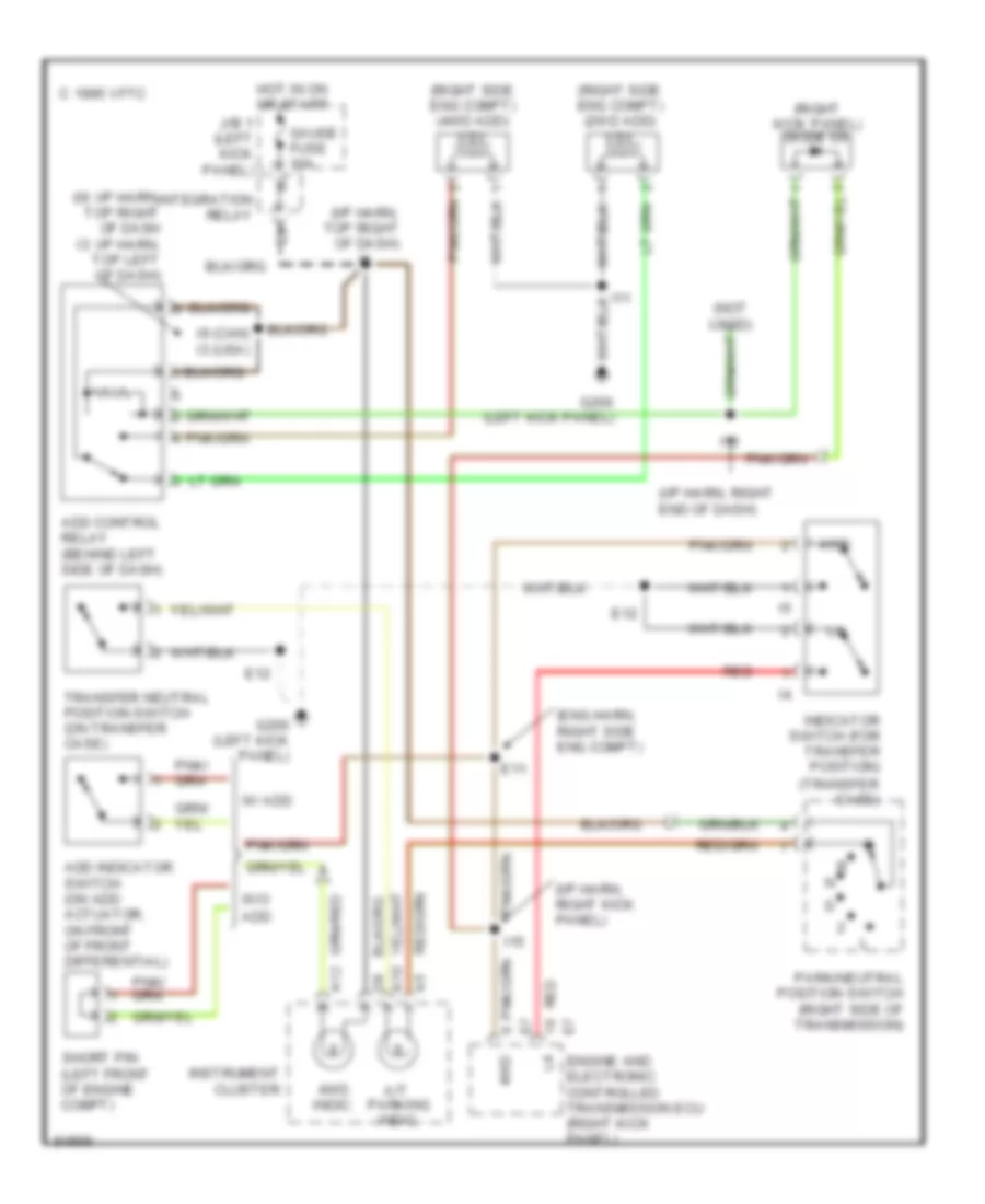
2.4L, Transfer Case Wiring Diagram, A/T for Toyota Pickup SR5 1995
List of elements for 2.4L, Transfer Case Wiring Diagram, A/T for Toyota Pickup SR5 1995:
- (eng harn, right side eng compt)
- (i/p harn, right end of dash)
- (i/p harn, right kick panel)
- (i/p harn, top right of dash)
- (i9: i/p harn, top right of dash i3: i/p harn, top left of dash)
- (not used)
- (right kick panel) diode d6
- (right side eng compt) (2wd add) vsv
- (right side eng compt) (4wd add) vsv
- (transfer case)
- 1995 vftc c
- 4wd
- 4wd indic.
- A/t parking indic.
- A10
- A12
- Add
- Add control relay (behind left side of dash)
- Add indicator switch (on add actuator, on front of front differential)
- E11
- E12
- Engine and electronic controlled transmission ecu (right kick panel)
- G200 (left kick panel)
- Gauge fuse 10a
- Hot in on or start
- I11
- I13
- I15
- I9 (can) i3 (usa)
- Indicator switch (for transfer position)
- Instrument cluster
- Integration relay
- J/b 1 (left kick panel)
- Park/neutral position switch (right side of transmission)
- Red
- Short pin (left front of engine compt)
- Transfer neutral position switch (on transfer case)
- W/ add
- W/o
Transfer Case Wiring Diagram, M/T for Toyota Pickup SR5 1995
List of elements for Transfer Case Wiring Diagram, M/T for Toyota Pickup SR5 1995:
- (eng harn, right side of eng)
- (i/p harn, right kick panel)
- (i/p harn, right kick panel) i15
- (i9: i/p harn, top right side of dash i13: i/p harn, right end of dash)
- 2.4l
- 3.0l
- 4wd
- 4wd indic.
- A12
- Add control relay (left side of dash)
- Add indicator switch (front differential)
- C 1995 vftc
- E20
- Engine control module (right kick panel)
- G200 (left kick panel)
- Gauge fuse 10a
- Hot in on or start
- I11
- I13 (canada) i9 (usa)
- I15
- I9 (i/p harn, top right side of dash)
- Indicator switch (transfer position) (on transfer case)
- Instrument cluster
- Integration relay
- J/b 1 (left kick panel)
- Red
- Vsv v1 (2wd add) (right side eng compt)
- Vsv v2 (4wd add) (right side eng compt)
- W/ add
Transmission Wiring Diagram for Toyota Pickup SR5 1995
List of elements for Transmission Wiring Diagram for Toyota Pickup SR5 1995:
- (4wd)
- (column shift only)
- (console shft) (floor shft)
- (right kick panel)
- (right side of engine compt) e11
- (top center of dash)
- (top right side of dash) i9
- (top right side of engine) e12
- * w/ 2.4l engine
- ** *
- ** nca
- ** w/ 3.0l v6 engine
- ***
- *** 3.0l v6 w/ 4wd
- ****
- **** all 2.4l, 3.0l v6 w/ 2wd
- 4wd
- Batt
- C17
- Cig fuse 15a
- Cruise control system
- Data link connector 1 (right side eng compt)
- Dg te2 t e1
- Efi fuse 15a
- Efi main
- Electronic controlled transmission solenoid and vehicle speed sensor
- Engine and electronic controlled transmission ecu (right kick panel)
- Engine coolant temperature sensor (on intake manifold)
- Exterior lights
- G100 (front of left front fender)
- G117 (cam bearing cap)
- G120 (intake mani- fold)
- G201 (right side of i/p)
- Gauge fuse 10a
- Hot at all times
- Hot in acc or on
- Hot in on or start
- I15
- I15 (right kick panel)
- I15 (rt kick pnl)
- I4 (top center of dash)
- I6 i8 (center of dash)
- Idl
- Ign fuse 7.5a
- Indicator switch (transfer position)
- Indicator switch (transfer position) (on t-case)
- Instrument cluster system
- Integration relay
- Interior lights system
- Interior lights system (floor shift)
- J/b 1 (left kick panel)
- N **
- Nca
- Nca **
- No. 1
- No. 2
- No. 3
- No. 4
- Norm
- O/d main switch
- O/d off
- O/d relay (left side of dash)
- O/d solenoid (right rear of engine compt)
- Od1
- Od2
- Oil
- Oil temp
- Oil temperature sensor (right front trans pan)
- Park/neutral position switch (right side of transmission)
- Pattern select switch
- Pwr
- Pwr indic
- R/b 2 (right eng compt)
- Red
- Relay
- Sp1
- Sp2
- Speedo
- Sta
- Starting/ charging system
- Stop fuse 15a
- Stop light switch (above brake pedal)
- Stp
- Te2
- Th01
- Th02 te2
- Throttle position sensor (on throttle body)
- Thw
- Transfer case
- Transfer fluid temperature sensor
- Transfer pressure switch (for add)
- Transmissions systems (a/t transfer case circuit)
- Turn fuse 10a
- Vcc
- Vehicle speed sensor
- Vta
3.0L
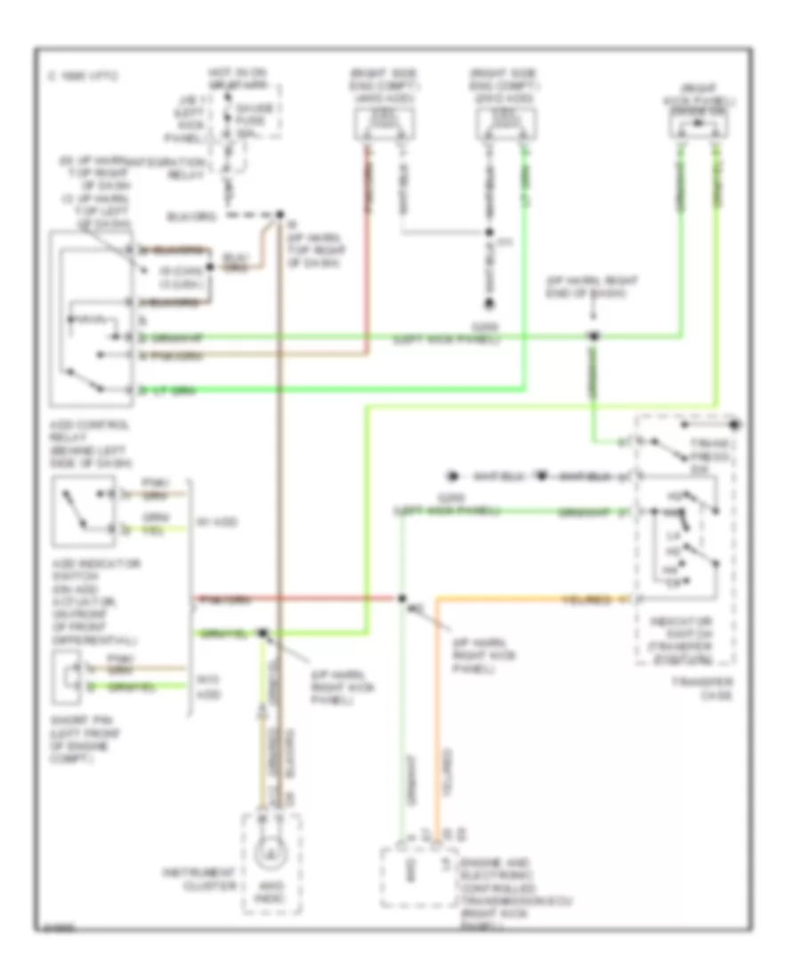
3.0L, Transfer Case Wiring Diagram, A/T for Toyota Pickup SR5 1995
List of elements for 3.0L, Transfer Case Wiring Diagram, A/T for Toyota Pickup SR5 1995:
- (i/p harn, right end of dash)
- (i/p harn, right kick panel)
- (i9: i/p harn, top right of dash i3: i/p harn, top left of dash)
- (left kick panel)
- (right kick panel) diode d6
- (right side eng compt) (2wd add) vsv
- (right side eng compt) (4wd add) vsv
- 1995 vftc c
- 4wd
- 4wd indic.
- A12
- Add
- Add control relay (behind left side of dash)
- Add indicator switch (on add actuator, on front of front differential)
- Engine and electronic controlled transmission ecu (right kick panel)
- G200
- G200 (left kick panel)
- Gauge fuse 10a
- Hot in on or start
- I11
- I13
- I15
- I9 (can) i3 (usa)
- I9 (i/p harn, top right of dash)
- Indicator switch (transfer position)
- Instrument cluster
- Integration relay
- J/b 1 (left kick panel)
- Short pin (left front of engine compt)
- Trans press sw
- Transfer case
- W/ add
- W/o
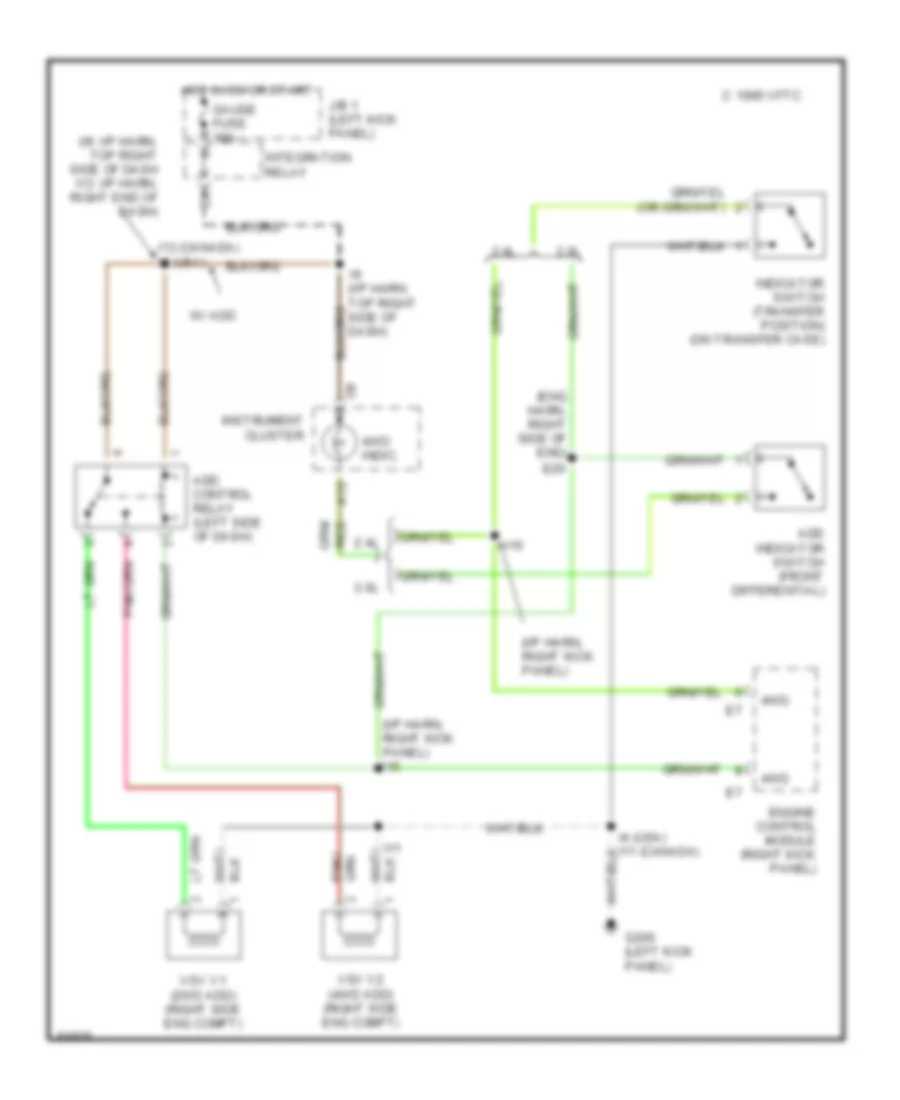
Transfer Case Wiring Diagram, M/T for Toyota Pickup SR5 1995
List of elements for Transfer Case Wiring Diagram, M/T for Toyota Pickup SR5 1995:
- (eng harn, right side of eng)
- (i/p harn, right kick panel)
- (i/p harn, right kick panel) i15
- (i9: i/p harn, top right side of dash i13: i/p harn, right end of dash)
- 2.4l
- 3.0l
- 4wd
- 4wd indic.
- A12
- Add control relay (left side of dash)
- Add indicator switch (front differential)
- C 1995 vftc
- E20
- Engine control module (right kick panel)
- G200 (left kick panel)
- Gauge fuse 10a
- Hot in on or start
- I11
- I13 (canada) i9 (usa)
- I15
- I9 (i/p harn, top right side of dash)
- Indicator switch (transfer position) (on transfer case)
- Instrument cluster
- Integration relay
- J/b 1 (left kick panel)
- Red
- Vsv v1 (2wd add) (right side eng compt)
- Vsv v2 (4wd add) (right side eng compt)
- W/ add
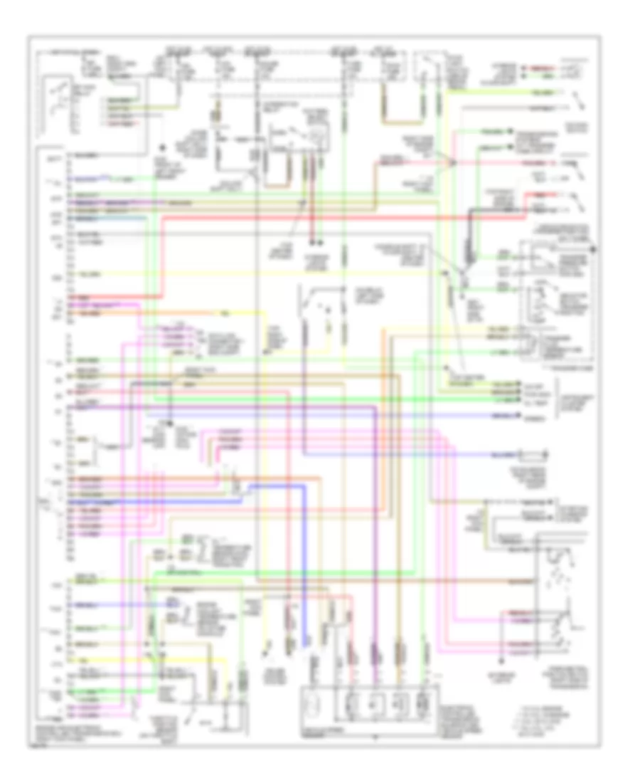
Transmission Wiring Diagram for Toyota Pickup SR5 1995
List of elements for Transmission Wiring Diagram for Toyota Pickup SR5 1995:
- (4wd)
- (column shift only)
- (console shft) (floor shft)
- (right kick panel)
- (right side of engine compt) e11
- (top center of dash)
- (top right side of dash) i9
- (top right side of engine) e12
- * w/ 2.4l engine
- ** *
- ** nca
- ** w/ 3.0l v6 engine
- ***
- *** 3.0l v6 w/ 4wd
- ****
- **** all 2.4l, 3.0l v6 w/ 2wd
- 4wd
- Batt
- C17
- Cig fuse 15a
- Cruise control system
- Data link connector 1 (right side eng compt)
- Dg te2 t e1
- Efi fuse 15a
- Efi main
- Electronic controlled transmission solenoid and vehicle speed sensor
- Engine and electronic controlled transmission ecu (right kick panel)
- Engine coolant temperature sensor (on intake manifold)
- Exterior lights
- G100 (front of left front fender)
- G117 (cam bearing cap)
- G120 (intake mani- fold)
- G201 (right side of i/p)
- Gauge fuse 10a
- Hot at all times
- Hot in acc or on
- Hot in on or start
- I15
- I15 (right kick panel)
- I15 (rt kick pnl)
- I4 (top center of dash)
- I6 i8 (center of dash)
- Idl
- Ign fuse 7.5a
- Indicator switch (transfer position)
- Indicator switch (transfer position) (on t-case)
- Instrument cluster system
- Integration relay
- Interior lights system
- Interior lights system (floor shift)
- J/b 1 (left kick panel)
- N **
- Nca
- Nca **
- No. 1
- No. 2
- No. 3
- No. 4
- Norm
- O/d main switch
- O/d off
- O/d relay (left side of dash)
- O/d solenoid (right rear of engine compt)
- Od1
- Od2
- Oil
- Oil temp
- Oil temperature sensor (right front trans pan)
- Park/neutral position switch (right side of transmission)
- Pattern select switch
- Pwr
- Pwr indic
- R/b 2 (right eng compt)
- Red
- Relay
- Sp1
- Sp2
- Speedo
- Sta
- Starting/ charging system
- Stop fuse 15a
- Stop light switch (above brake pedal)
- Stp
- Te2
- Th01
- Th02 te2
- Throttle position sensor (on throttle body)
- Thw
- Transfer case
- Transfer fluid temperature sensor
- Transfer pressure switch (for add)
- Transmissions systems (a/t transfer case circuit)
- Turn fuse 10a
- Vcc
- Vehicle speed sensor
- Vta

 Čeština
 Dansk
Dansk Deutsch
 Ελληνικά
 English
 English
 Español
 Suomi
Suomi Français
 Français
 עברית
עברית Hrvatski
 Magyar
 Italiano
 日本語
日本語 한국어
한국어 Nederlands
 Polski
 Português
 Português
 Română
 Русский
 Slovenčina
 Slovenščina
 Türkçe
 中文 (中国)