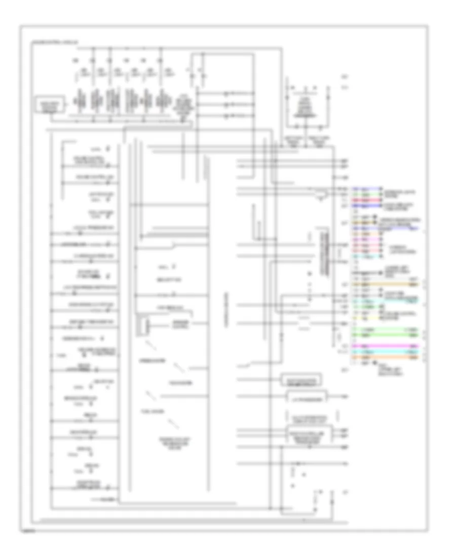
AIR CONDITIONING
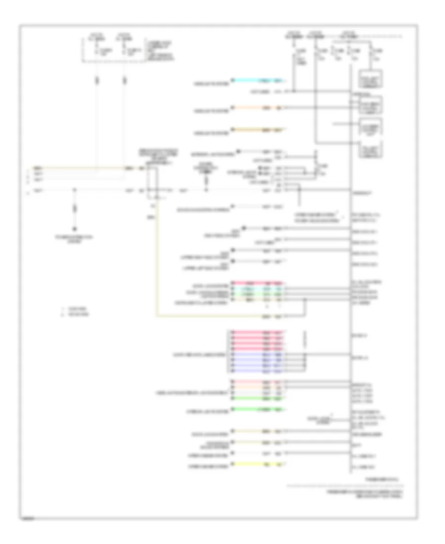
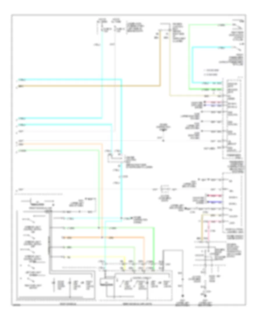
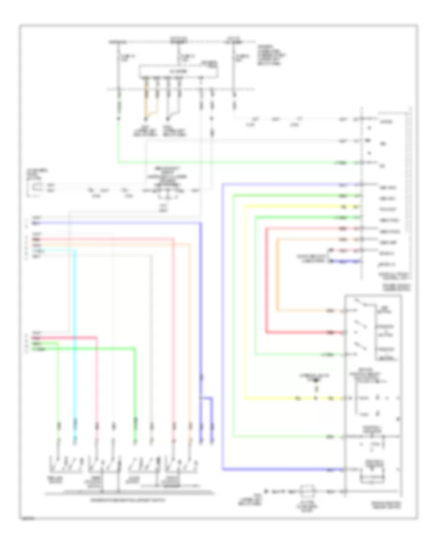
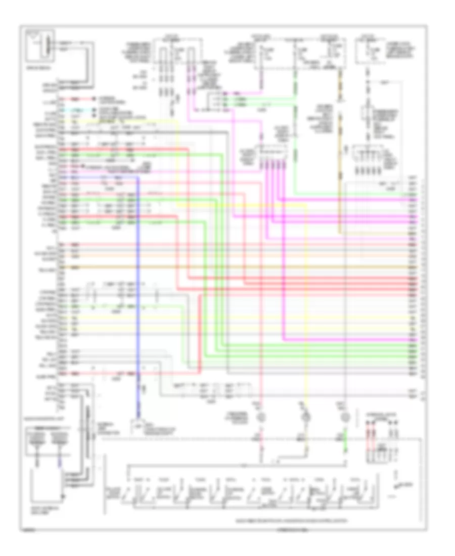
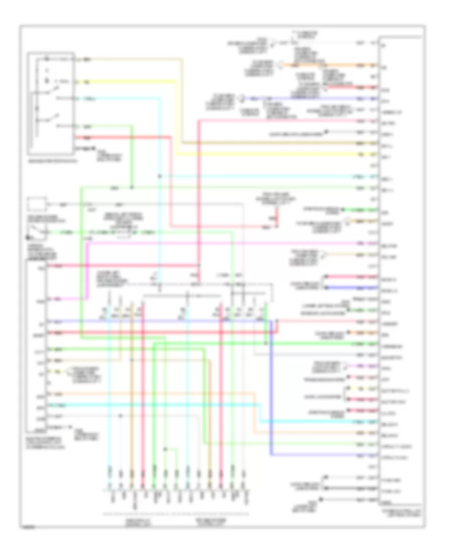
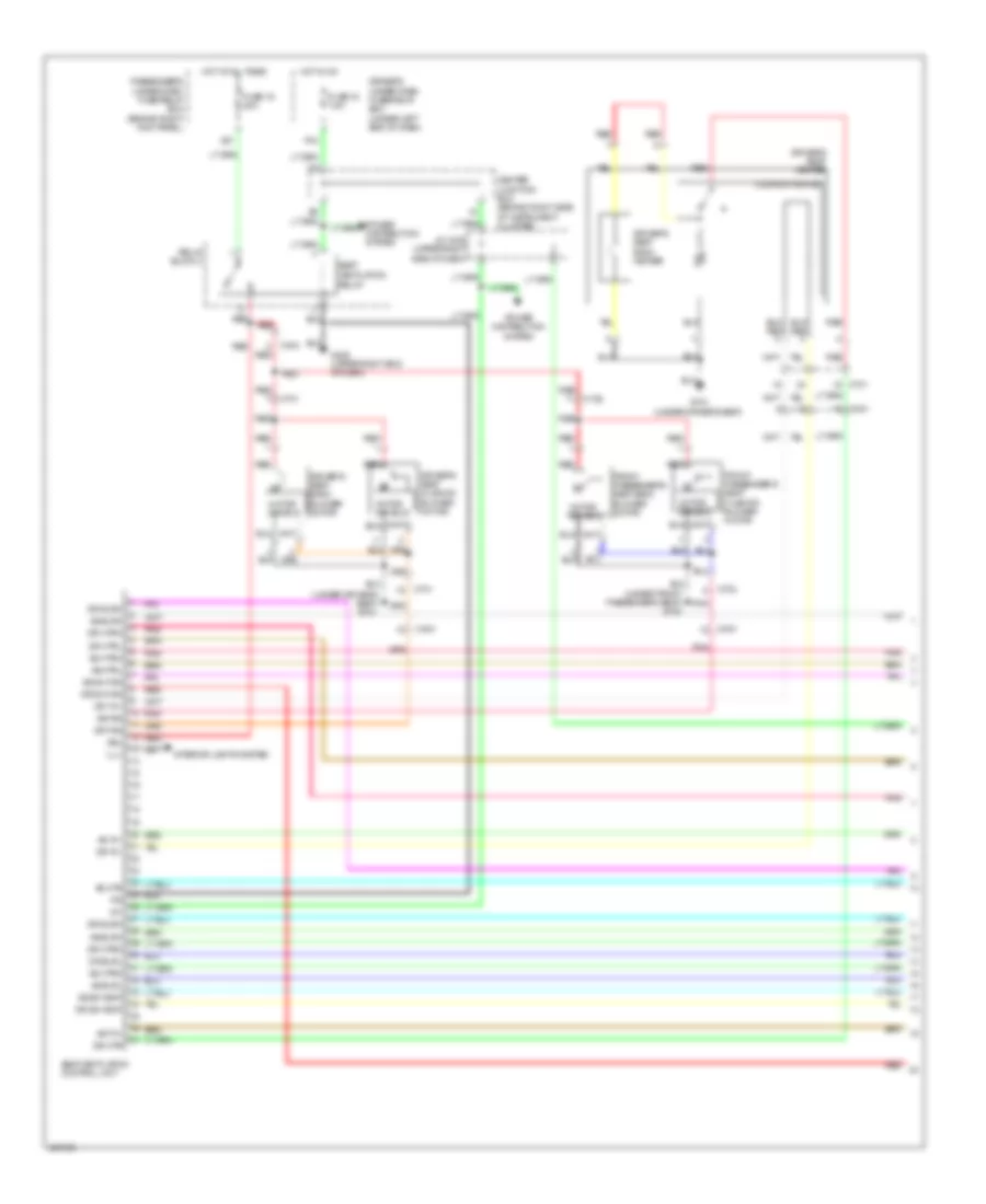
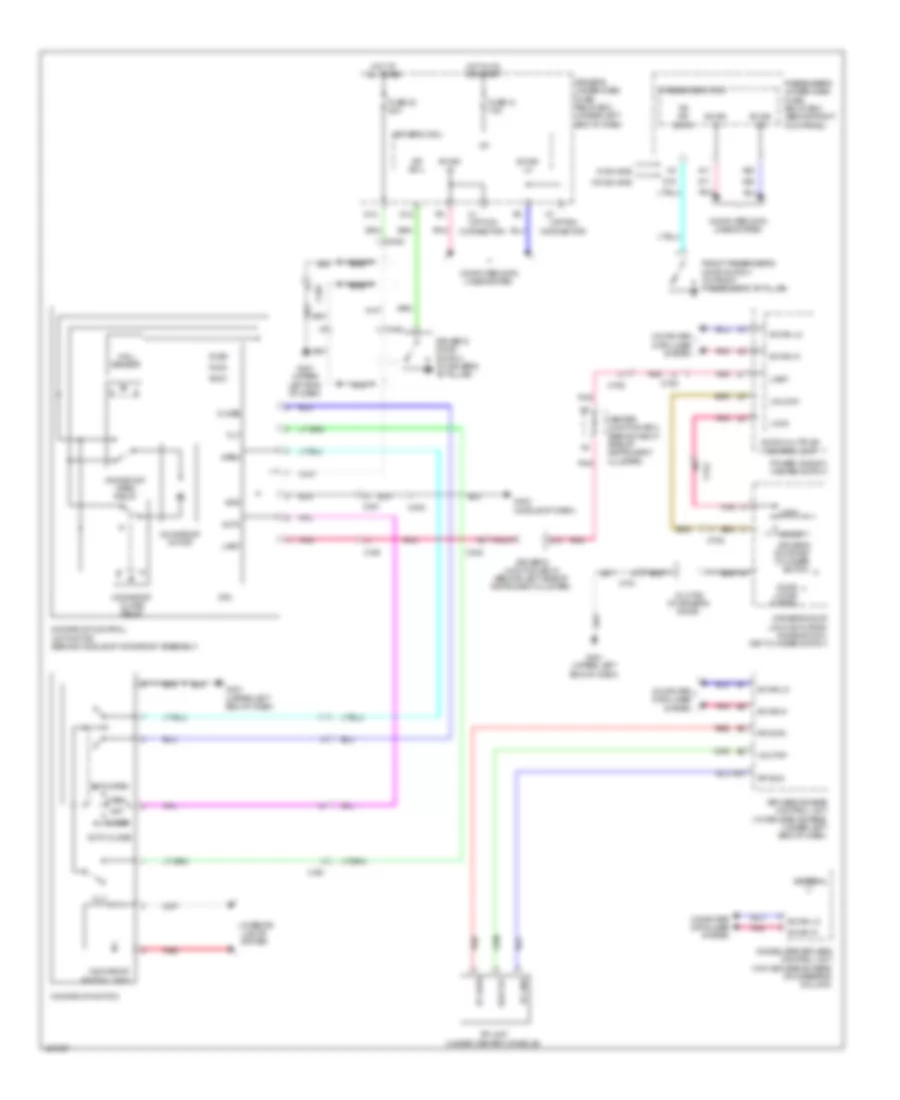
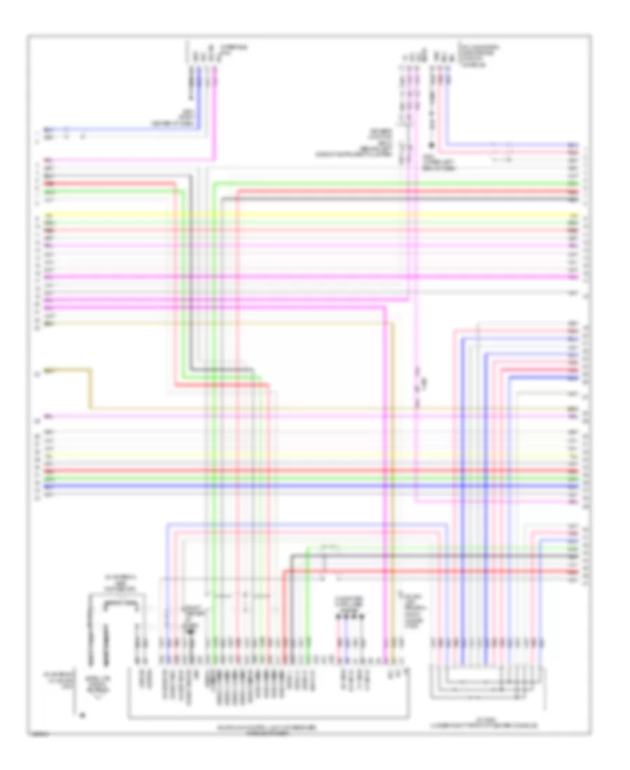
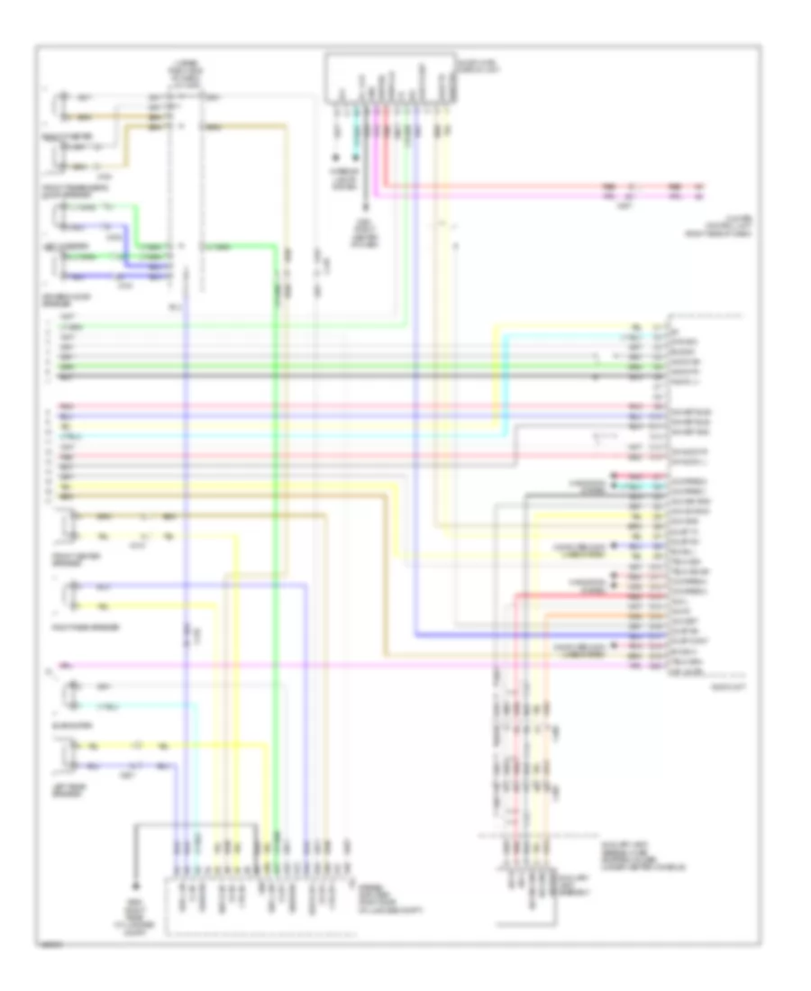
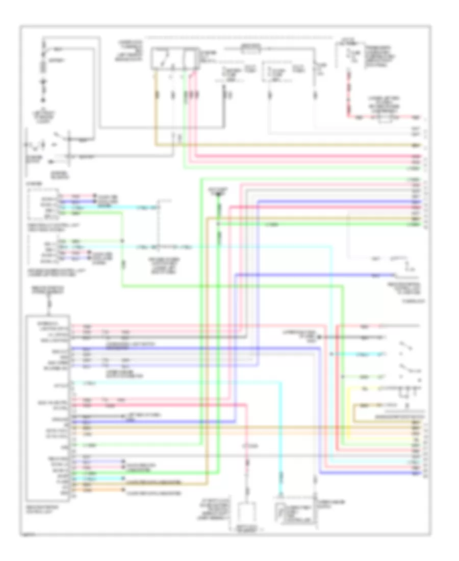
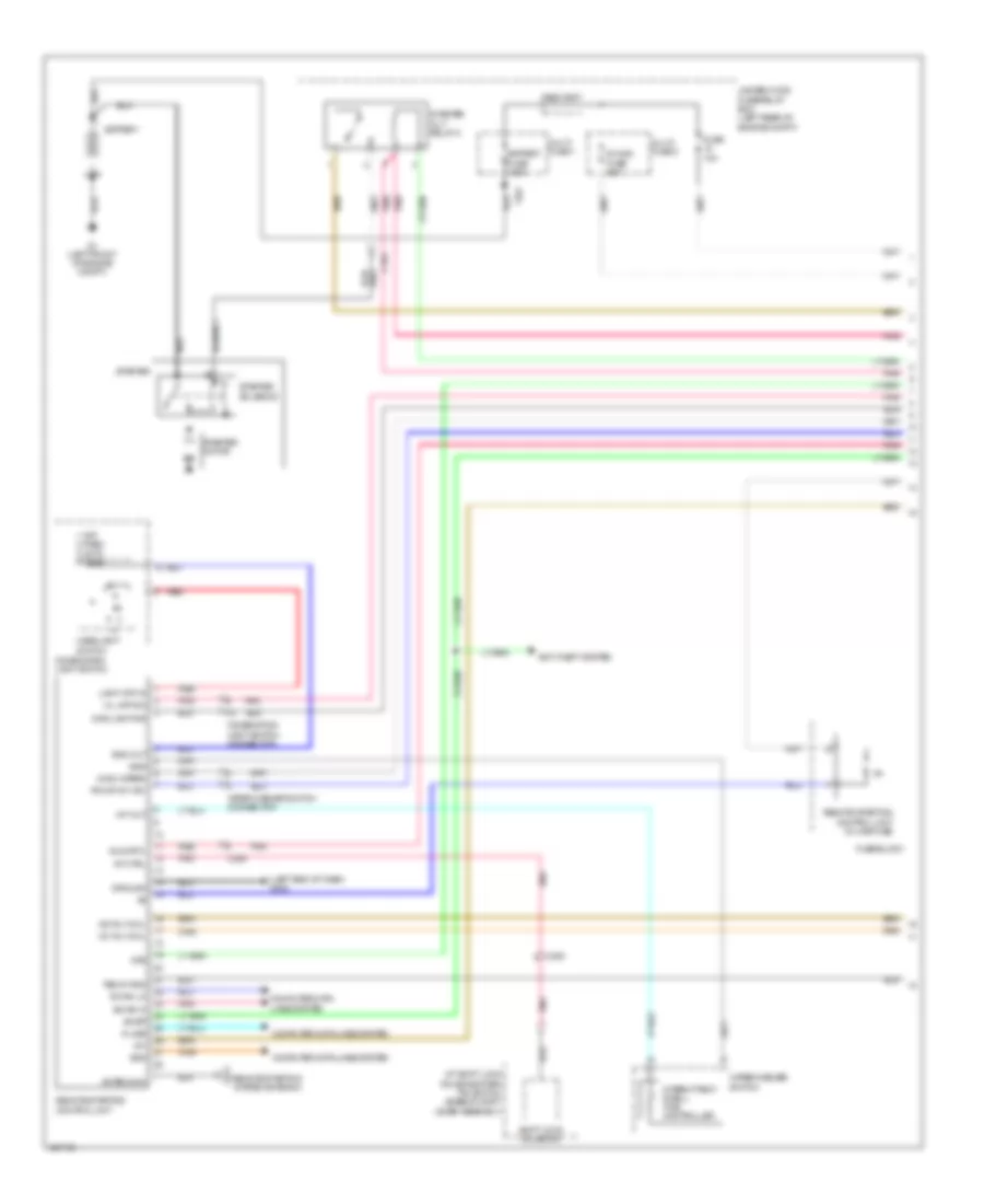
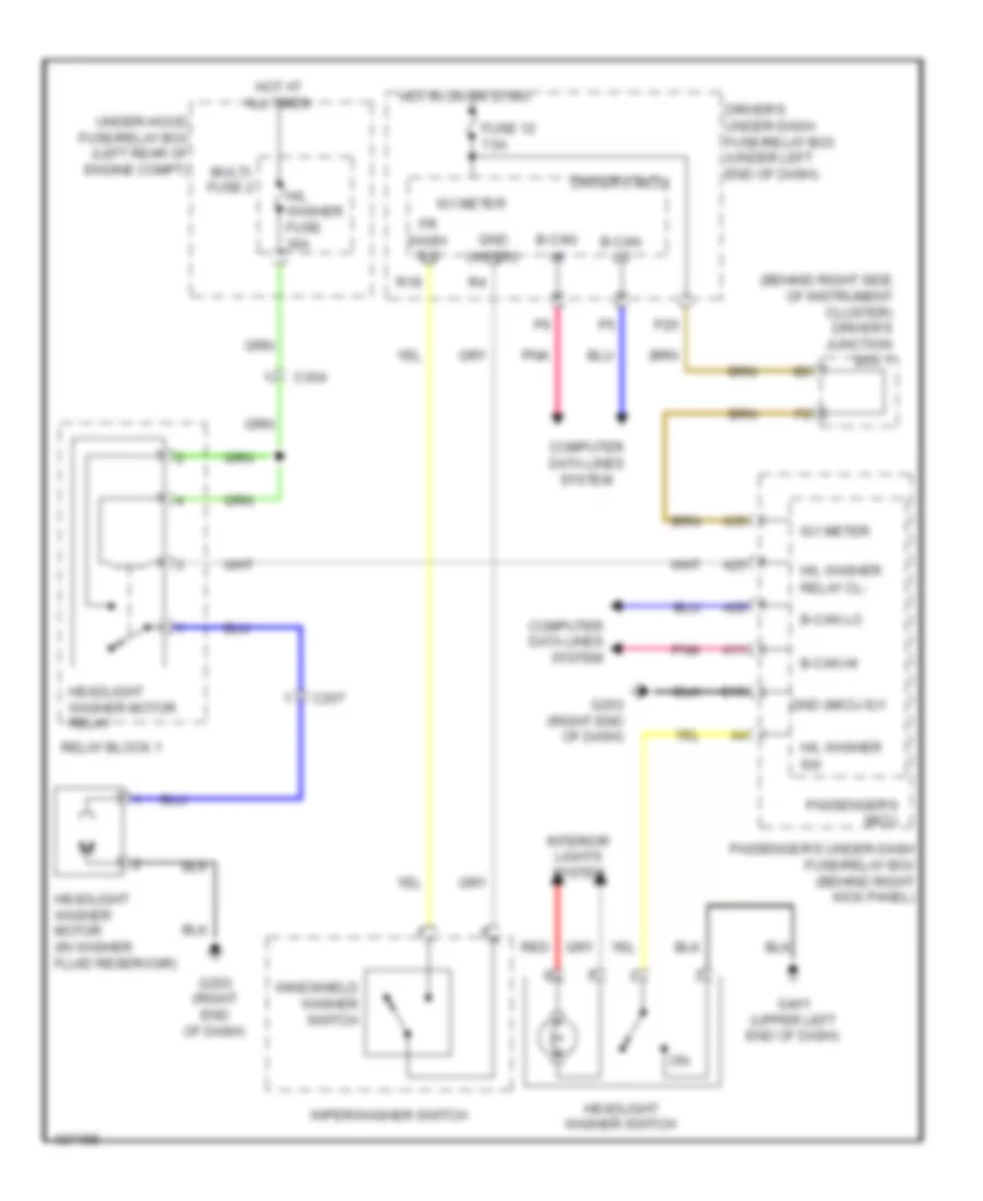
Automatic A/C Wiring Diagram (1 of 3) for Acura TL 2014
 https://portal-diagnostov.com/license.html
Automotive Electricians Portal FZCO
Automotive Electricians Portal FZCO
https://portal-diagnostov.com/license.html
https://portal-diagnostov.com/license.html
Automotive Electricians Portal FZCO
Automotive Electricians Portal FZCO
List of elements for Automatic A/C Wiring Diagram (1 of 3) for Acura TL 2014:
- (behind left end of front bumper) g301
- (behind left side of radiator) radiator fan motor
- (upper right side of dash) j/c c408
- A/c diode b
- A/c pressure sensor (right rear of engine compt)
- A1 ground
- A10 m-hot
- A11 m-cool
- A12 m-hot
- A13
- A14
- A15 ig2
- A16
- A17 mode 1
- A18 mode 2
- A19 mode 3
- A20 mode 4
- A21 mode 1
- A22 mode 2
- A23 mode 3
- A24 mode 4
- A25 amd-p
- A26 amd-p
- A27 blw-v
- A28 blw-g
- A29
- A30 ill+
- A7 m-def
- A8 m-vent
- A9 m-cool
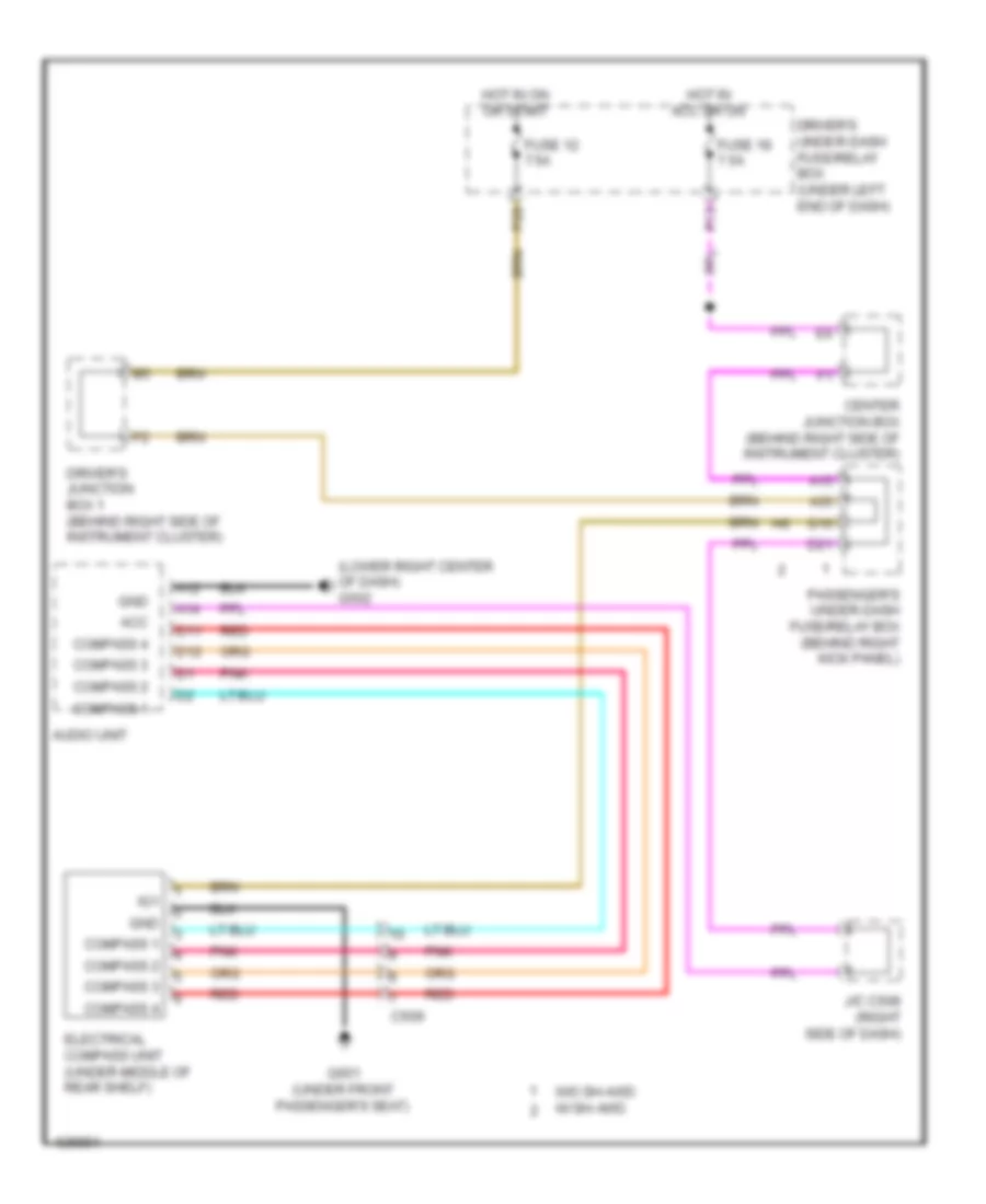
- Audio navigation switch panel
- Audio navigation unit (w/ navigation)
- Audio-hvac display unit
- B10
- C1 s-com
- C10 rec
- C11 pd
- C12 hum
- C13
- C14 t sun
- C15 tr
- C16 teva
- C17 tam
- C18 mode 1
- C19 mode 2
- C2 s5v
- C20 mode 3
- C206
- C306
- C4 ac si
- C403
- C406
- C5 ac so
- C501
- C6 ac clk
- C7 b can lo
- C8 b can hi
- C9 frs
- Center junction box (behind right side of instrument cluster)
- Climate control unit (right side of dash)
- Computer data lines system
- Disp clk
- Disp so
- Driver's under-dash fuse/relay box (under left end of dash)
- Evaporator temperature sensor (left side of hvac evaporator assembly)
- F26
- Fuse 7.5a
- G403 (middle of dash)
- Hot at all times
- Hot in on
- Hot w/ pgm-fi sub relay energized
- Humidity sensor
- Humidity/in-car temperature sensor (lower left center of dash)
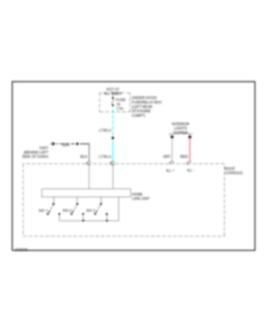
- Interior lights system
- J/c c408 (upper right side of dash)
- M-def
- M-vent
- Main fan motor fuse 30a
- Multi fuse 3
- Navi clk
- Navi si
- Navi so
- Outside air temperature sensor (behind left center of front bumper)
- P18
- Pnk
- Radiator fan relay
- Red
- Relay circuit board
- Seats system
- To fan control relay (diagram 2 of 3)
- Under-hood fuse/relay box (left rear of engine compt)
- W/ navigation
- W/o navigation
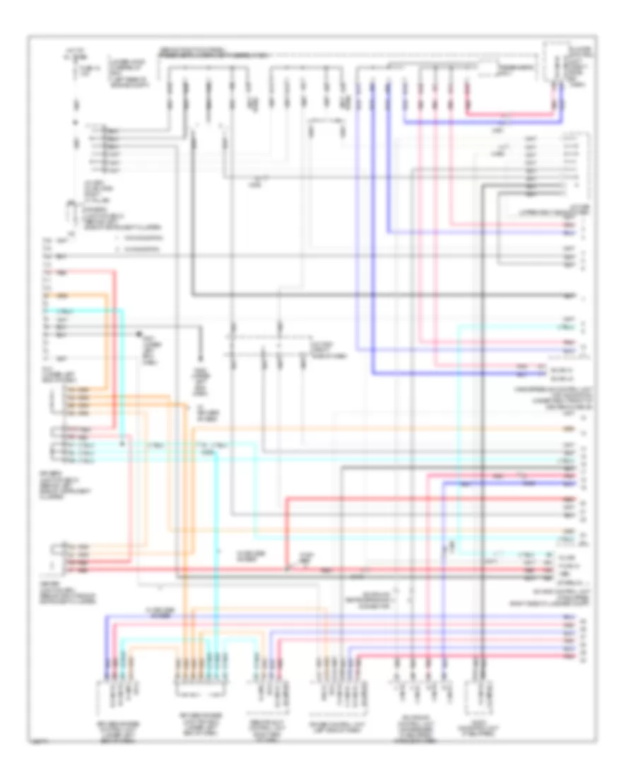
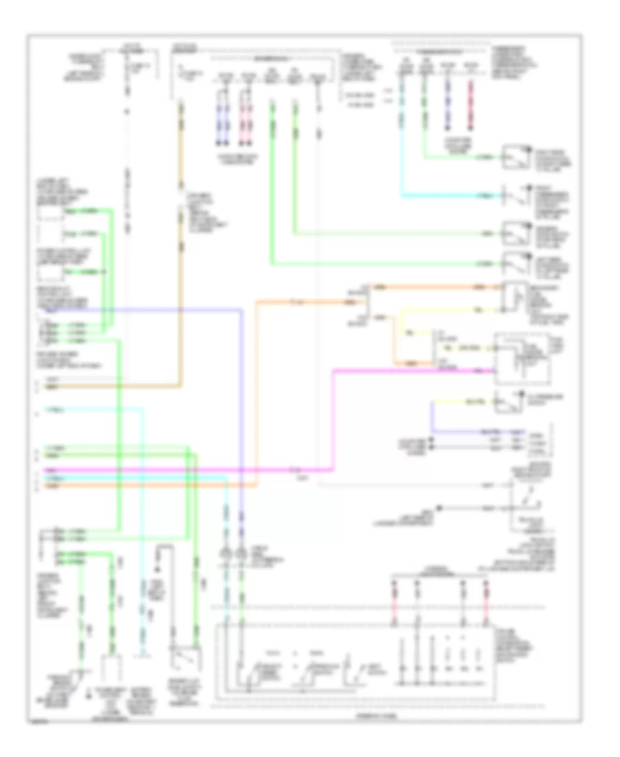
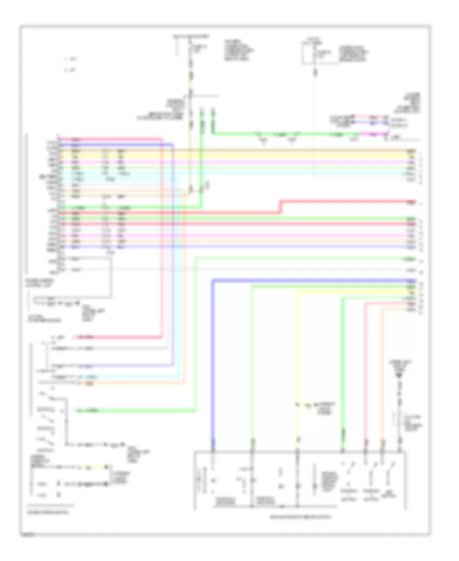
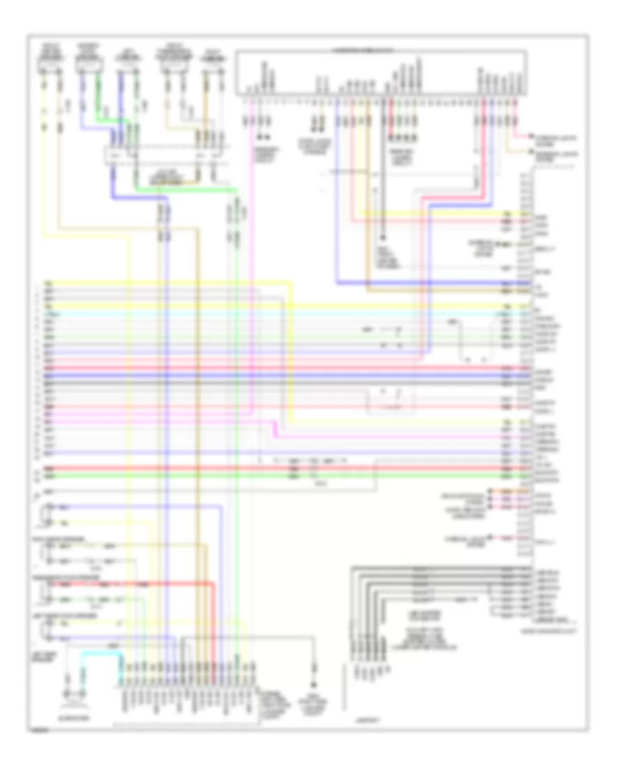
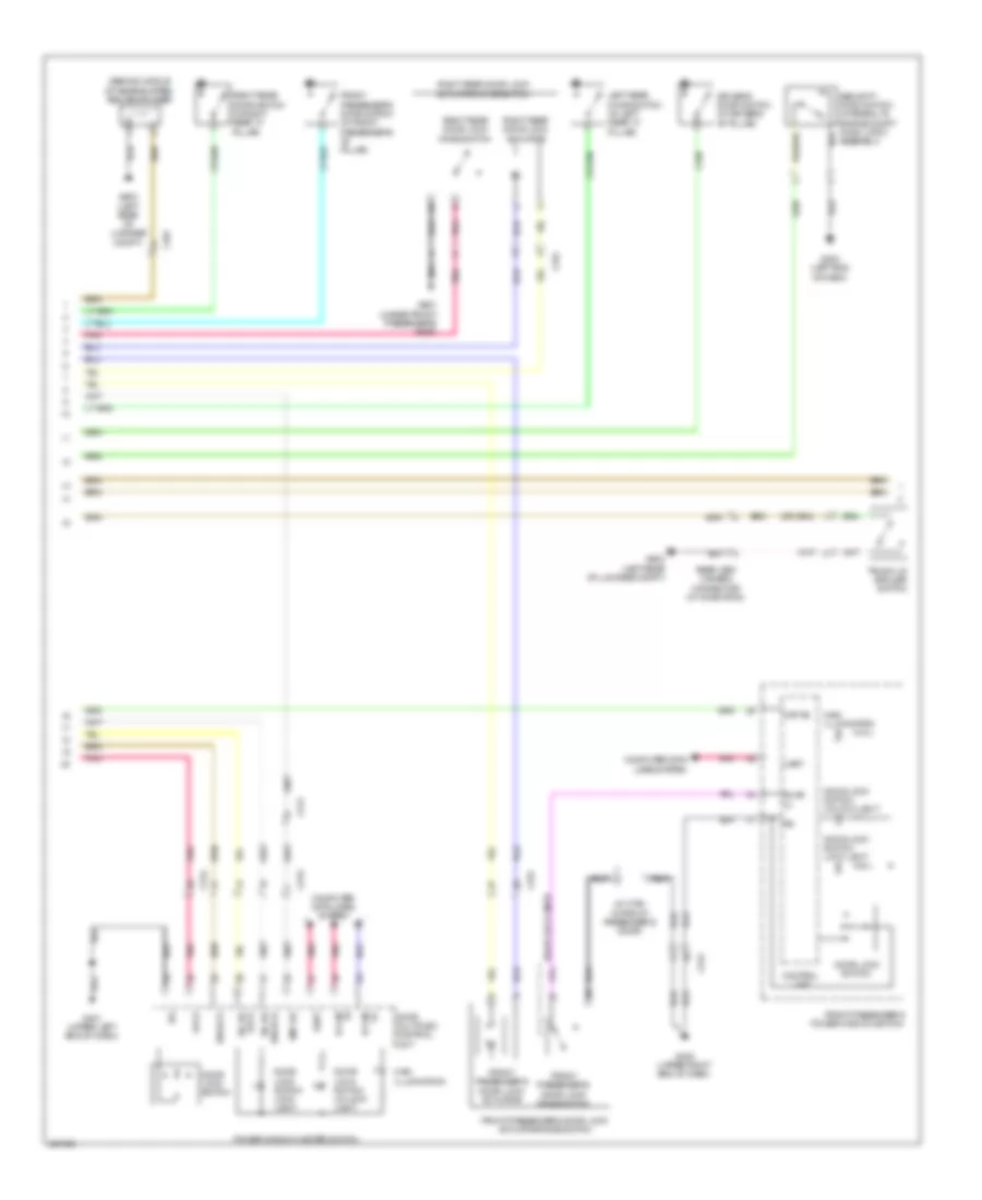
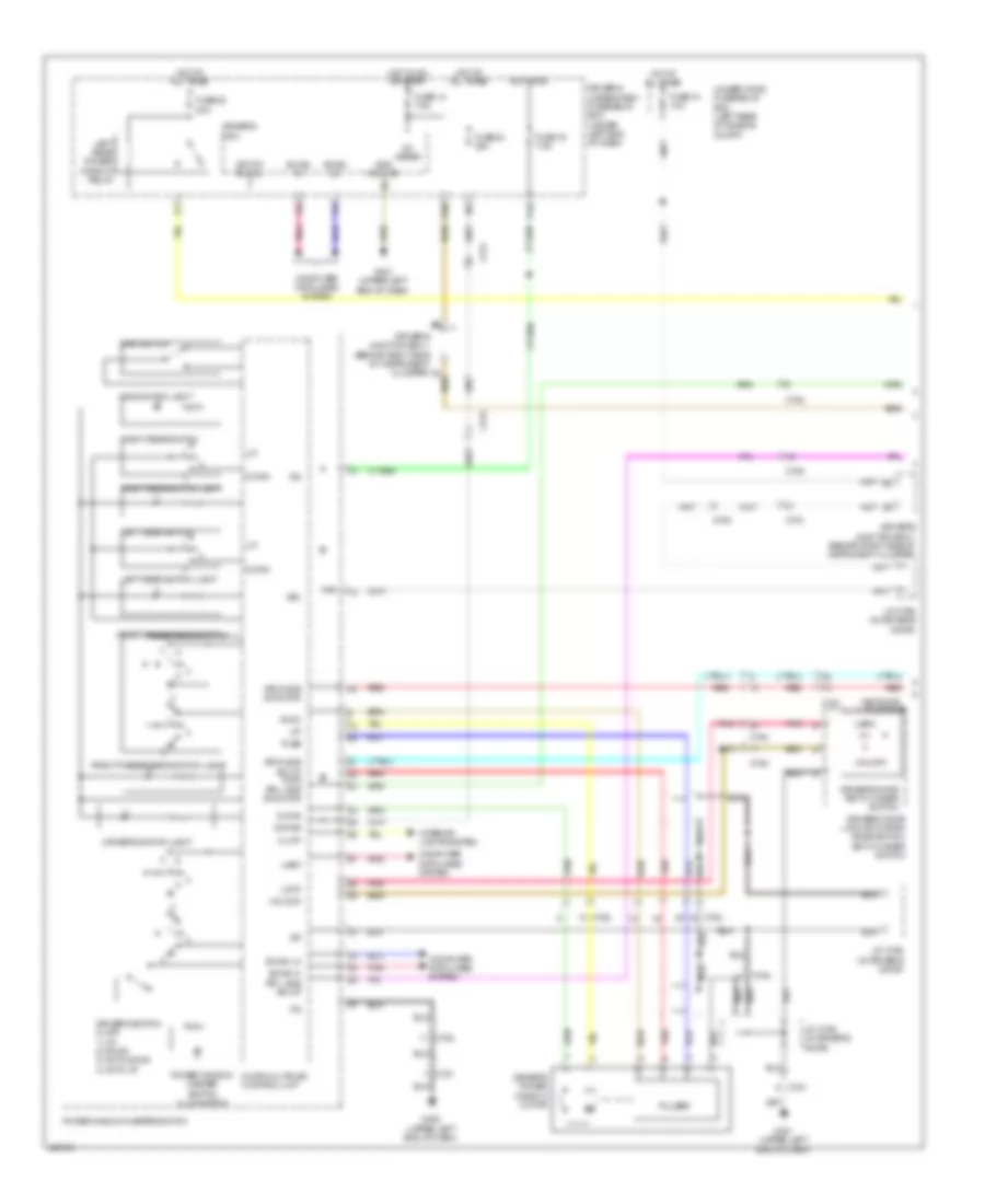
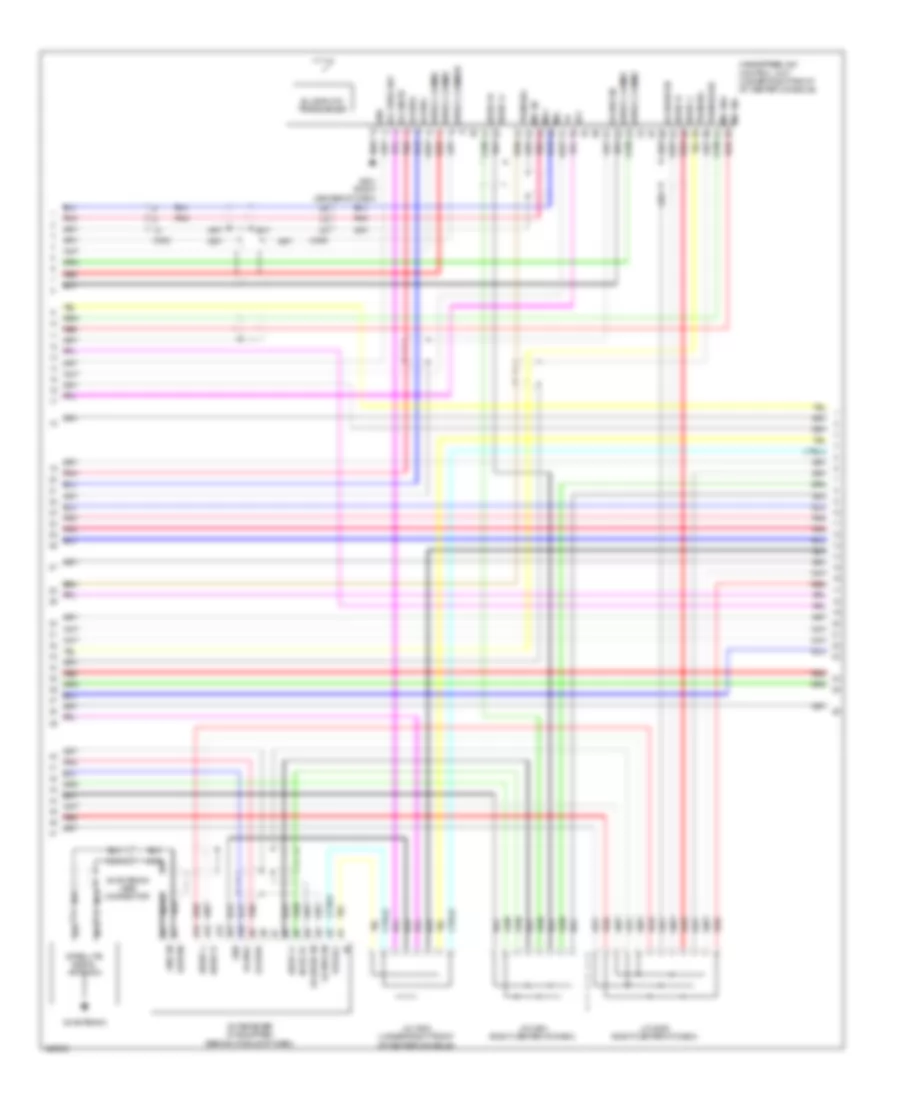
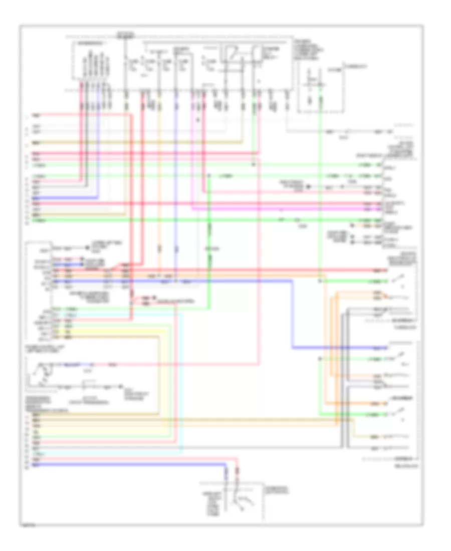
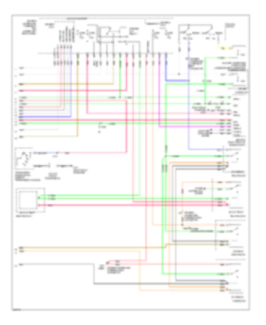
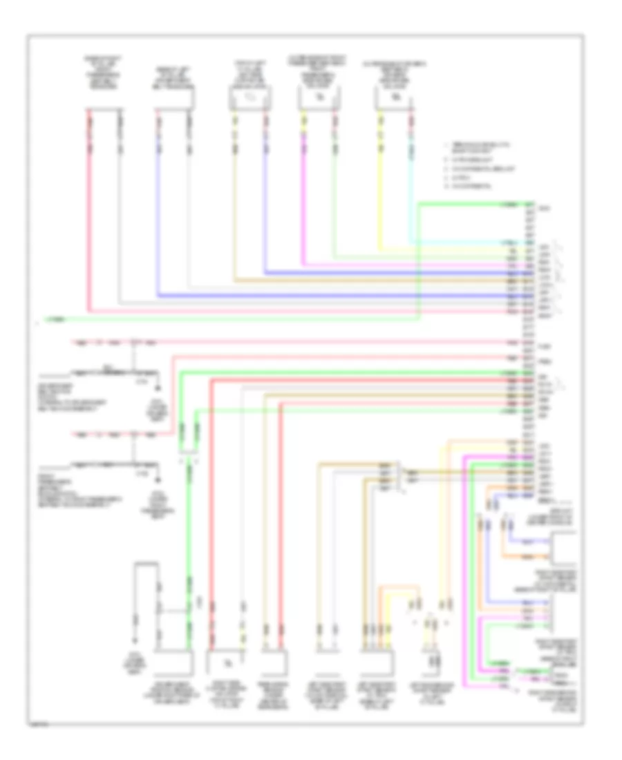
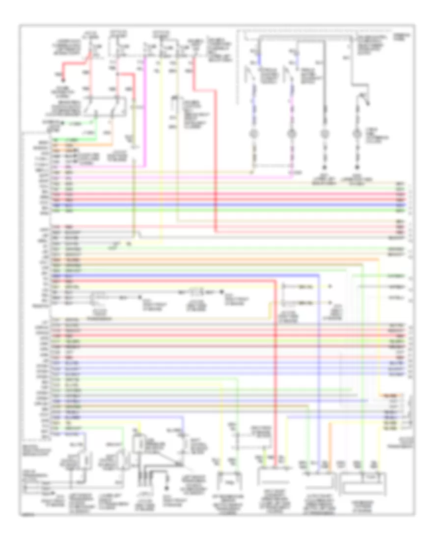
Automatic A/C Wiring Diagram (2 of 3) for Acura TL 2014
List of elements for Automatic A/C Wiring Diagram (2 of 3) for Acura TL 2014:
- (diagram 1 of 3)
- (right side of engine) j/c c107
- A/c compressor clutch relay
- A/c condenser fan relay
- A/c diode a
- A13
- A21
- A27
- A48
- A49
- Acc
- Amd-p
- Blower motor relay
- C16
- C32
- C403
- Computer data lines system
- Driver's air mix control motor (lower left side of hvac unit)
- Ecm/pcm (right front of engine compt)
- Ect sensor 1 (top left rear of engine)
- Ect sensor 2 (lower left rear of radiator)
- Ect1
- Ect2
- F can h
- F can l
- Fan control relay
- Fan relay b
- Fanh
- Fanl
- From radiator a
- Front passenger's air mix control motor (lower right side of hvac unit)
- Frs
- Fuse 40a
- Fuse 7.5a
- G301 (behind left end of front bumper)
- G302 (left end of dash)
- Hot at all times
- J/c c307 (left side of dash)
- M-cool
- M-hot
- Mode 1
- Mode 2
- Mode 3
- Multi fuse-3
- Pnk
- Rear window defogger relay
- Rec
- Recirculation control motor (under left side of hvac blower housing)
- Red
- Relay circuit board
- S-com
- S5v
- Sg2
- Sg4
- Sub fan motor fuse 30a
- Sunlight sensor (top center of dash)
- Under-hood fuse/relay box (left rear of engine compt)
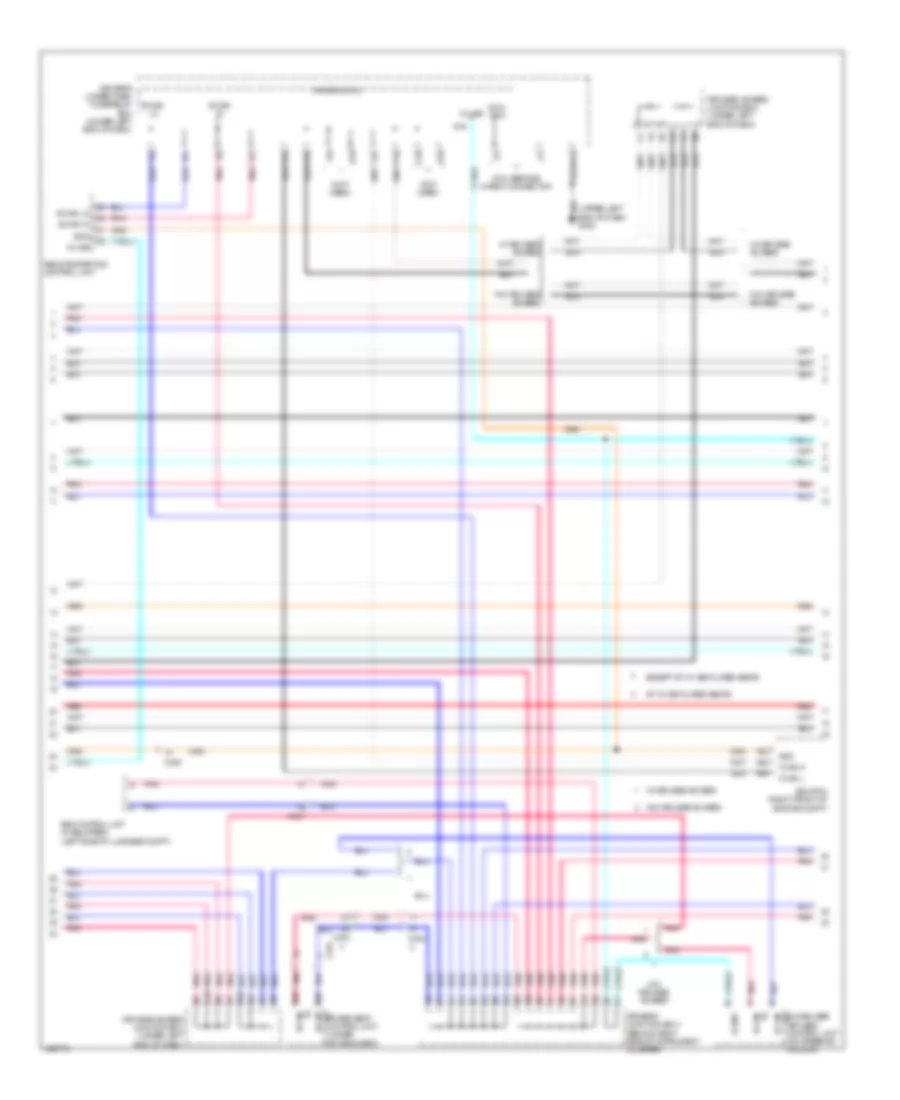
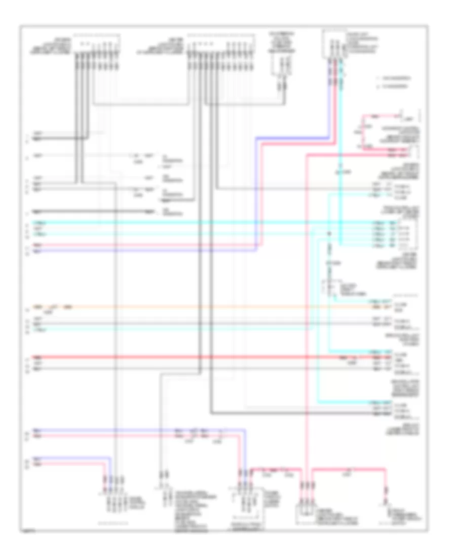
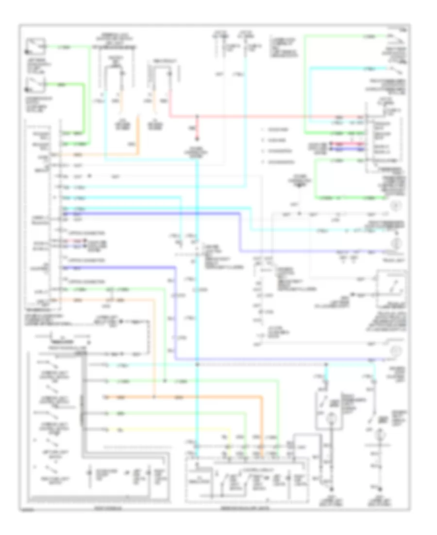
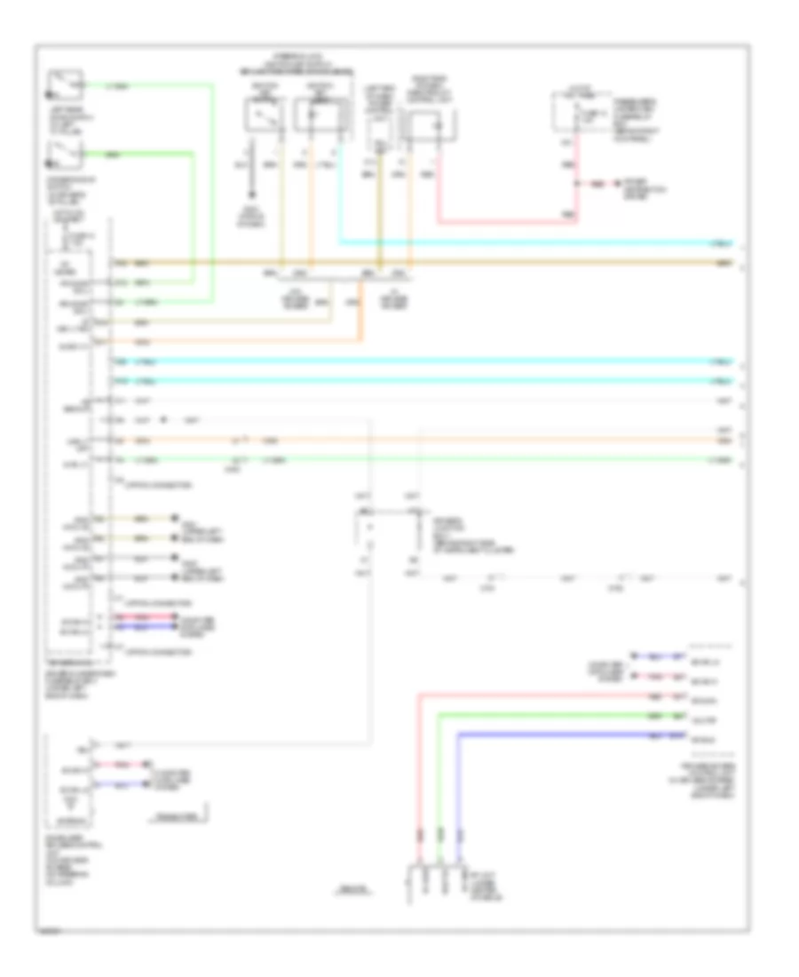
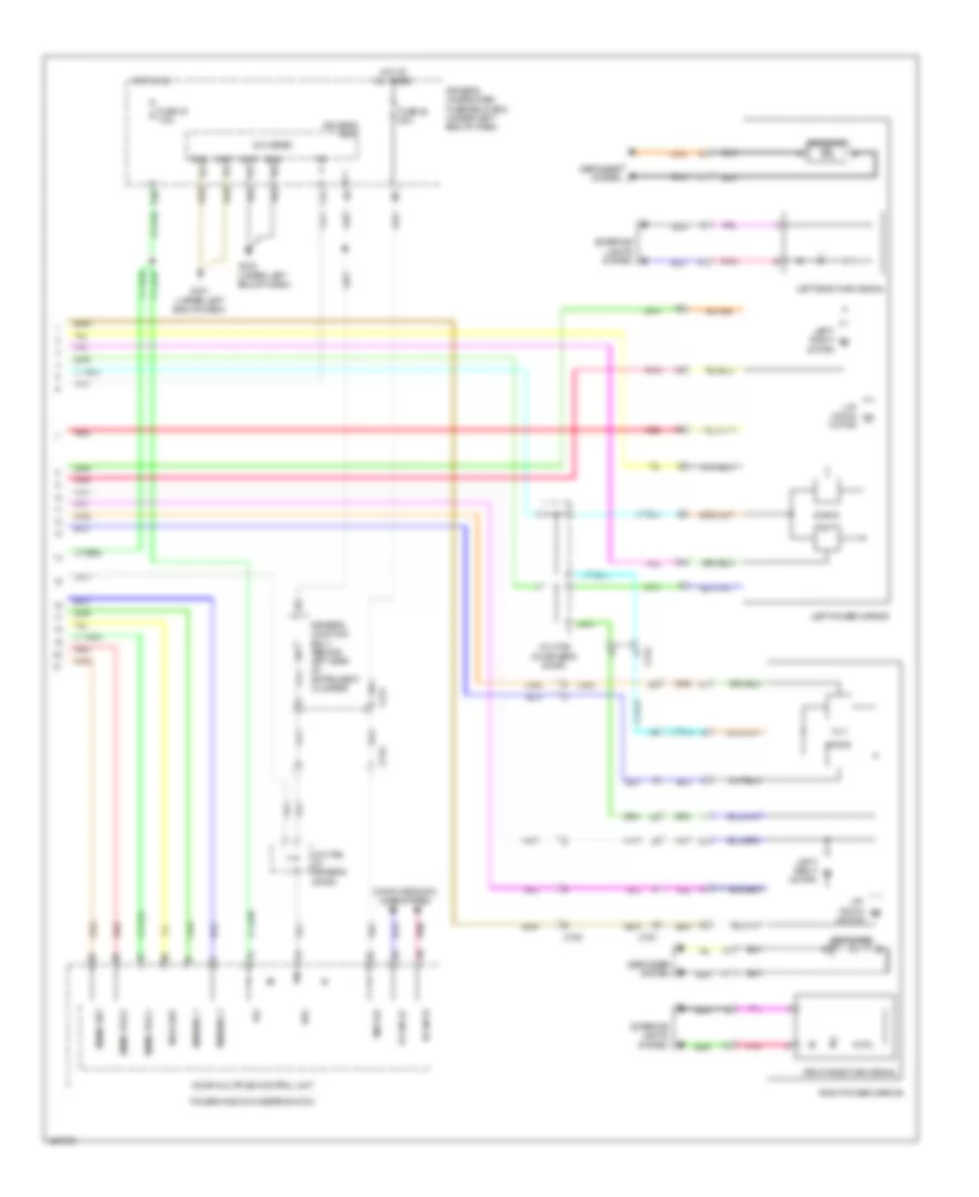
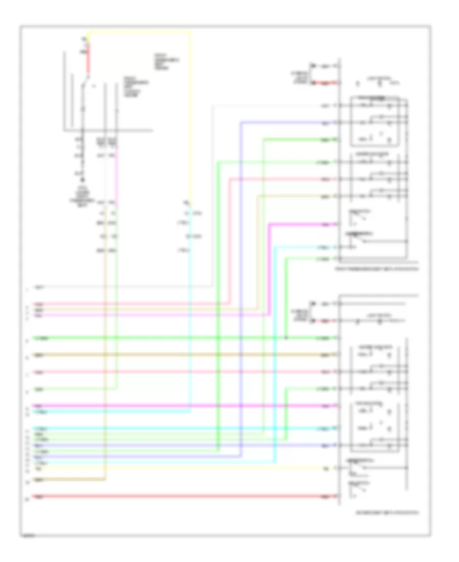
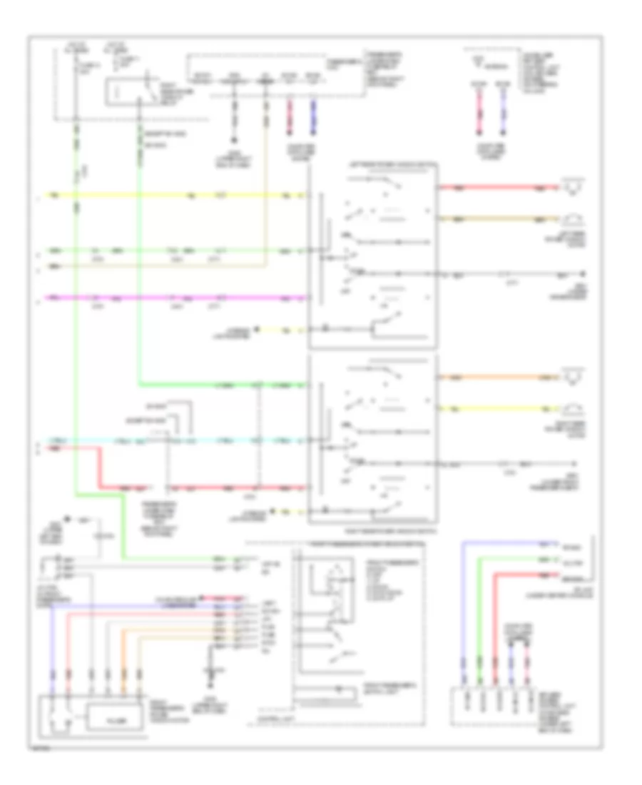
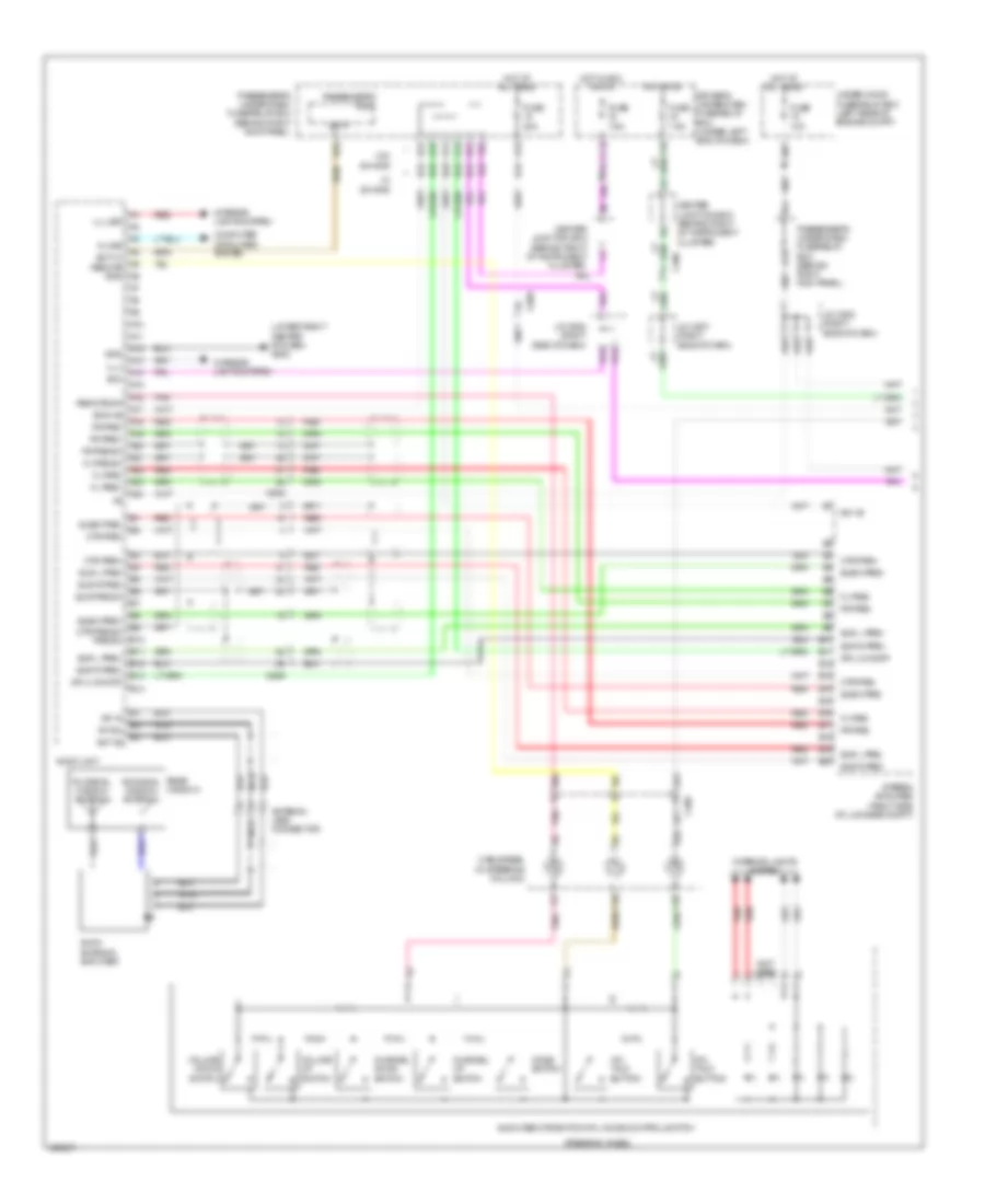
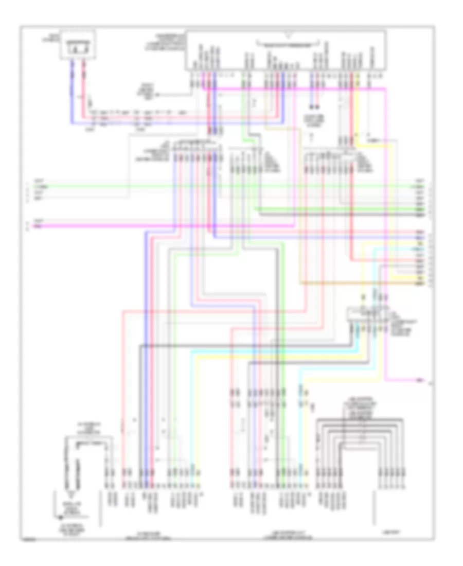
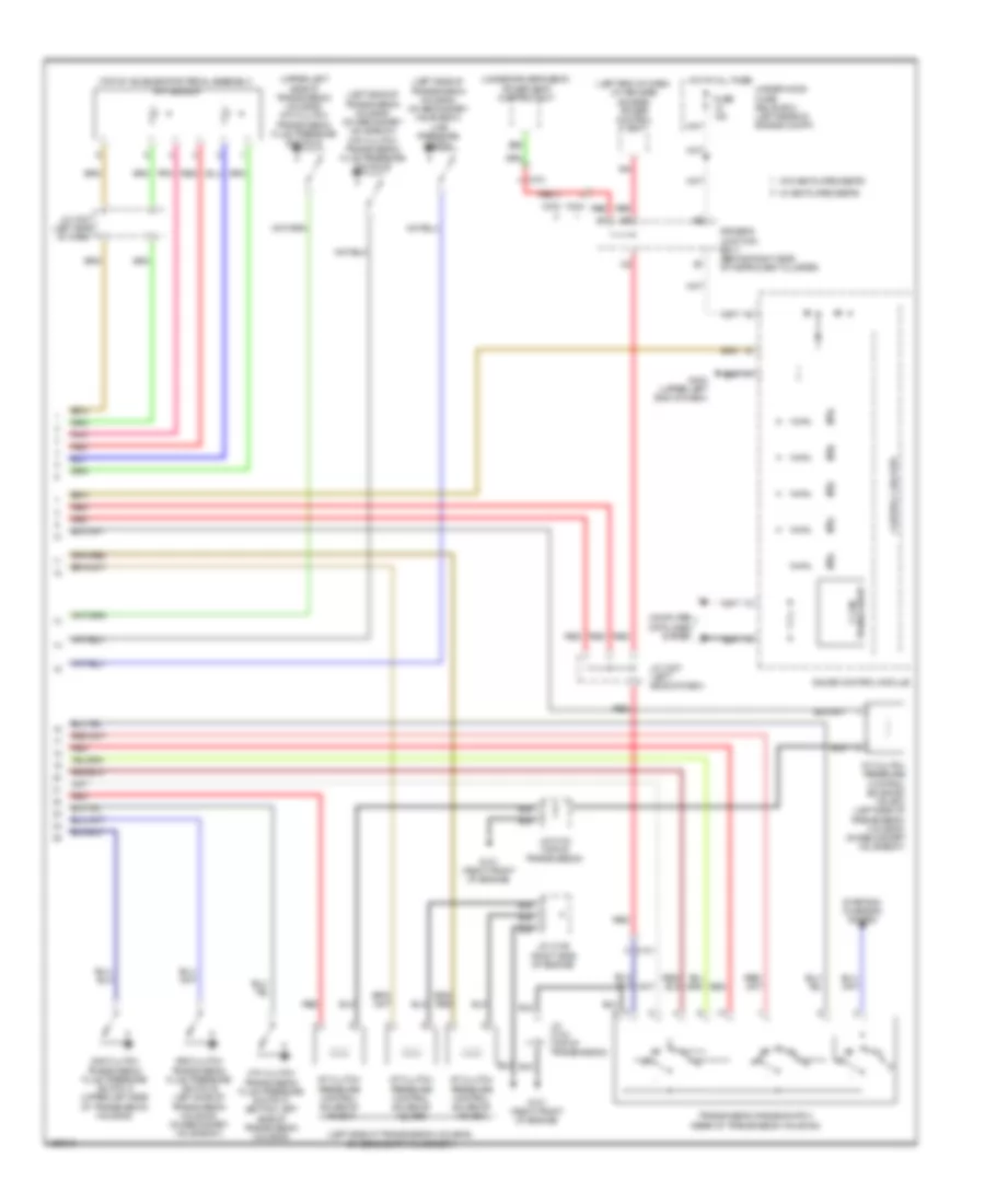
Automatic A/C Wiring Diagram (3 of 3) for Acura TL 2014
List of elements for Automatic A/C Wiring Diagram (3 of 3) for Acura TL 2014:
- (front of hvac unit) blower power transistor
- A/c compressor (lower left front of engine)
- A/c compressor clutch
- A/c condenser fan motor (behind right side of radiator)
- B10
- B11
- B12
- B13
- B14
- B15
- B16
- B17
- B18
- B19
- B20
- B21
- B22
- B23
- B24
- Blower motor (under right side of dash)
- C101
- C301
- C302
- C403
- C406
- C501
- Climate control unit (right side of dash)
- Def led
- Dr in1
- Dr in2
- Dr in3
- Dr in4
- Dr in5
- Dr in6
- Dr in7
- Dr in8
- Dr ind pwm
- Driver's climate control switch
- Driver's mode control motor (under left side of hvac unit)
- Fr led
- Front passenger's climate control switch
- Front passenger's mode control motor (upper right side of hvac unit)
- G302 (left end of dash)
- G403 (middle of dash)
- G405 (upper right end of dash)
- Gnd
- Ig2
- Ill+
- Ill-
- Ind pwm
- Interior lights system
- J/c c507 (right side of dash)
- M-def
- M-vent
- Mode 1
- Mode 2
- Mode 3
- Mode 4
- Pnk
- Ps in1
- Ps in2
- Ps in3
- Ps in4
- Ps in5
- Ps in6
- Ps in7
- Ps in8
- Ps ind pwm
- Red
- Rr def led
- Rr def lfd
- S-com
- Sync led
ANTI-LOCK BRAKES
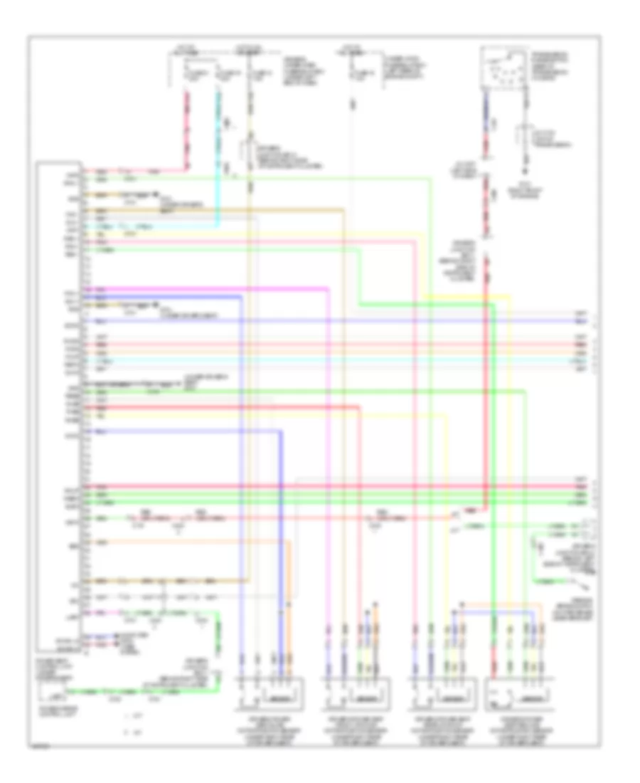
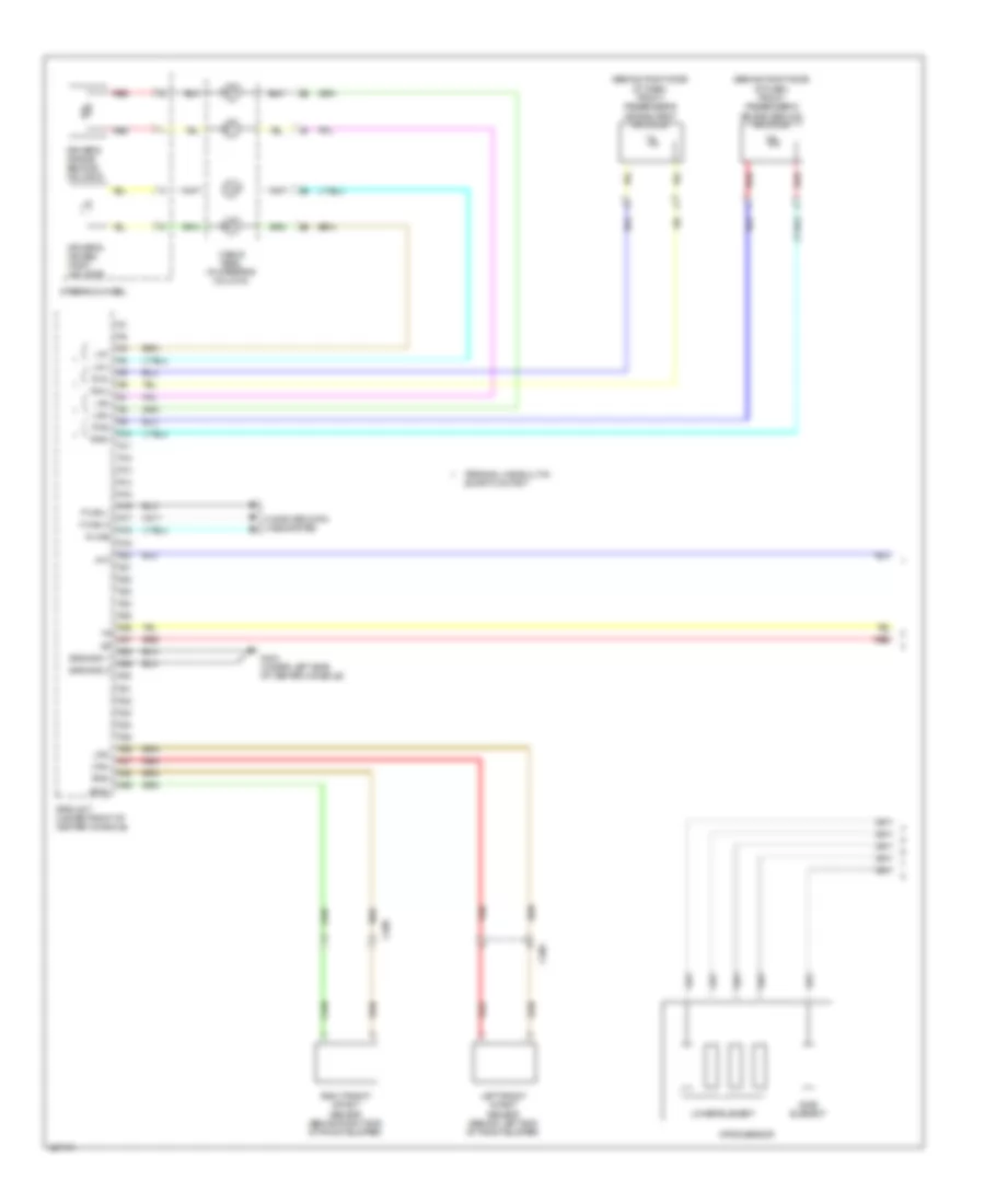
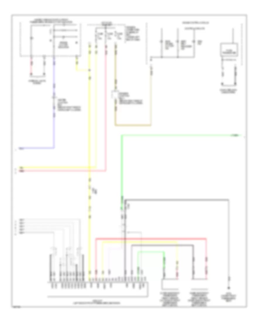
Anti-lock Brakes Wiring Diagram (1 of 2) for Acura TL 2014
List of elements for Anti-lock Brakes Wiring Diagram (1 of 2) for Acura TL 2014:
- (on steering column) (w/ sh-awd) steering angle sensor
- (right end of dash) eps control unit
- (under front of center console) (w/ sh-awd) yaw rate-lateral/ longitudinal acceleration sensor (w/o sh-awd) yaw rate-lateral acceleration sensor
- A22
- A48
- A49
- Abs/ vsa fuse 30a
- Abs/vsa motor fuse 40a
- Back lt
- Bksw
- Bkswnc
- Brake pedal position switch (on brake pedal mounting bracket)
- C201
- C206
- C306
- C401
- Can h
- Can l
- Center junction box (behind right side of instrument cluster)
- Computer data lines system
- D16
- Driver's under-dash fuse/relay box (under left end of dash)
- Ecm/pcm (right front of engine compt)
- Exterior lights system
- F-can h
- F-can l
- F14
- Fl+b
- Fl-gnd
- Fr-gnd
- Fsr+b
- Fuse 10 20a
- Fuse 13 15a
- Fuse 6 7.5a
- G202 (behind right end of front bumper)
- G401 (upper left end of dash)
- G403 (middle of dash)
- Gnd
- Hot at all times
- Hot in on or start
- Ig1
- Ignition 1
- K-line
- Left front wheel speed sensor (on left front wheel hub assembly)
- Left rear wheel speed sensor (on left rear wheel hub assembly)
- Mr+b
- Mr-gnd
- Multi- fuse 2
- Passenger's under-dash fuse/relay box (behind right kick panel)
- Pnk
- Power distribution system
- Red
- Right front wheel speed sensor (on right front wheel hub assembly)
- Right rear wheel speed sensor (on right rear wheel hub assembly)
- Rl+b
- Rl-gnd
- Rr+b
- Rr-gnd
- Sens gnd
- Spd sens in
- Str-a
- Str-b
- Str-z
- Svcc
- Under-hood fuse/relay box (left rear of engine compt)
- Vsa modulator control unit (right side of engine compt)
- W/ sh-awd
- W/o sh-awd
- Wen
Anti-lock Brakes Wiring Diagram (2 of 2) for Acura TL 2014
List of elements for Anti-lock Brakes Wiring Diagram (2 of 2) for Acura TL 2014:
- Abs ind
- Brake fluid level switch (on brake fluid reservoir)
- Brake system ind
- C206
- C306
- C405
- Computer data lines system
- Control circuits
- Driver's junction box 1 (behind right side of instrument cluster)
- Driver's junction box 2 (behind left side of instrument cluster)
- Driver's under-dash fuse/relay box (under left end of dash)
- E10
- F-can transceiver
- Fuse 12 7.5a
- Fuse 15 10a
- G302 (left end of dash)
- G401 (upper left end of dash)
- Gauge control module
- Hot at all times
- Hot in on or start
- Interior lights system
- P20
- Parking brake switch (on park brake lever bracket)
- Red
- Sens gnd
- Steering angle sensor (w/o sh-awd) (on steering column)
- Str a
- Str b
- Str z
- Svcc
- Under-hood fuse/relay box (left rear of engine compt)
- Vsa off ind
- Vsa off switch
- Vsa system ind
ANTI-THEFT
Forced Entry Wiring Diagram, with Keyless Access (1 of 5) for Acura TL 2014
List of elements for Forced Entry Wiring Diagram, with Keyless Access (1 of 5) for Acura TL 2014:
- (not used)
- A11
- A20
- A24
- A28
- A29
- A38
- As d/l lk rly cl
- As d/l unlk rly cl
- B-can hi
- B-can lo
- Buzzer keyless
- C751
- C761
- C771
- Computer data lines system
- D/l sil- con rr-r
- D/l sil-con sw rr-l
- D12
- D15
- Door key
- Door lock knob
- Door lock relay
- Door unlock relay
- Dr d/l rly cl
- Dr side d/l rly cl
- Dr side d/l unl rly cl
- Driver's door key cylinder switch
- Driver's door lock actuator
- Driver's door lock actuator/ knob switch/key cylinder switch
- Driver's door lock knob switch
- Driver's door unlock relay
- Driver's micu
- Driver's under-dash fuse/relay box (under left end of dash)
- Eng hood sw
- F23
- Fr door sw l
- Fr dr sw r
- Fuse 10a
- Fuse 15a
- Fuse 20a
- Fuse 7.5a
- G14
- G15
- G401 (upper left end of dash)
- G601 (under driver's seat)
- G651 (under front passenger's seat)
- H22
- H25
- H27
- Horn sw
- Horns system
- Hot at all times
- Hot in on or start
- Ig key lt sw
- Ig1 mtr
- J/c c755 (in driver's door)
- Left rear door lock actuator
- Left rear door lock actuator/knob switch
- Left rear door lock knob switch
- N16
- Passenger's micu
- Passenger's under-dash fuse/relay box (behind right kick panel)
- Pnk
- Q12
- Q18
- Rr door sw l
- Rr dr sw r
- Trunk handle sw horn rly cl
- W/ sh-awd
- W/o sh-awd
Forced Entry Wiring Diagram, with Keyless Access (2 of 5) for Acura TL 2014
List of elements for Forced Entry Wiring Diagram, with Keyless Access (2 of 5) for Acura TL 2014:
- (behind middle of rear bumper) keyless buzzer
- B-can lo
- C401
- C751
- C753
- C754
- C761
- C781
- Computer data lines system
- Control unit
- Door lock knob
- Door lock switch
- Door lock switch lock light
- Door lock switch unlock light
- Door multiplex control unit
- Driver's door switch (in driver's "b" pillar)
- Front passenger's door lock actuator
- Front passenger's door lock actuator/knob switch
- Front passenger's door lock knob switch
- Front passenger's door switch (in front passenger's "b" pillar)
- Front passenger's power window switch
- G302 (left end of dash)
- G401 (upper left end of dash)
- G405 (upper right end of dash)
- G603 (left rear of luggage compt)
- G651 (under front passenger's seat)
- Hi b-can
- J/c c762 (in front passenger's door)
- Left rear door switch (in left rear "c" pillar)
- Lock
- Lock sil dr
- Main illumination
- Pnk
- Power window master switch
- Rear view camera connector (w/ navigation)
- Right rear door lock actuator
- Right rear door lock actuator/knob switch
- Right rear door lock knob switch
- Right rear door switch (in right rear "c" pillar)
- Security hood switch (integral to engine compt hood latch assembly)
- Sil dr unlock
- Silas ul
- Trunk lid spoiler switch
- Uart
- Unlock
- Vmp as
- Vmp dr
Forced Entry Wiring Diagram, with Keyless Access (3 of 5) for Acura TL 2014
List of elements for Forced Entry Wiring Diagram, with Keyless Access (3 of 5) for Acura TL 2014:
- (left end of dash) power control unit
- (under left end of dash) keyless access junction box
- +b backup
- +b cut relay (m/t)
- +b sm art
- +b smart
- A48
- A49
- Acc
- B can hi
- B can lo
- B-can transceiver
- C13
- C14
- C20
- C22
- C23
- C26
- C27
- C29
- C30
- C31
- C32
- C34
- C35
- C36
- C407
- Computer
- Computer data lines system
- Control circuits
- Data lines system
- Dck
- Din/dout
- Driver's junction box 1 (behind right side of instrument cluster)
- Ecm/pcm (right front of engine compt)
- Ele key sw
- Electric steering lock control unit (in steering column)
- Engine start/stop switch
- Esl pwr
- Esl sw b
- Esl sw c
- Esl sw d
- Esl swb
- F-can h
- F-can l
- F-can-h
- F-can-l
- G401 (upper left end of dash)
- G402 (upper left end of dash)
- G405 (upper right end of dash)
- G501 (right center of dash)
- Gauge control module
- Gnd
- Gnd-2
- Hbrake sw
- Ig1
- Ign trx
- K-line
- Keyless access indicator
- Keyless access system mode switch
- Lg1
- Lg2
- M/t
- Mtr cnt
- Mtr cut 1
- Mtr cut 2
- Pcu key
- Pnk
- Red
- Relay block 2
- Remote slot control unit (right end of dash)
- S-net
- Scs
- Security indicator
- Slot sw full
- Slot sw full2
- Slot sw half
- Slot sw half hbrake sw
- Slot sw lock
- Sol +
- Sol-
- Ss1 (+)
- Ss2 (-)
- Vout slot
Forced Entry Wiring Diagram, with Keyless Access (4 of 5) for Acura TL 2014
List of elements for Forced Entry Wiring Diagram, with Keyless Access (4 of 5) for Acura TL 2014:
- A10
- Audio navigation unit
- Audio unit
- C306
- C405
- Center junction box (behind right side of instrument cluster)
- D22
- Driver's junction box 1 (behind right side of instrument cluster)
- Driver's junction box 2 (behind left side of instrument cluster)
- Driver's micu
- Driver's under-dash fuse/relay box (under left end of dash)
- F11
- Fc ic
- Fob lock solenoid
- Fuse 10a
- Fuse 20a
- Fuse 7.5a
- G403 (middle of dash)
- Hall ic
- Hot at all times
- Hot in on or acc
- Hot in on or start
- K10
- Keyless access junction box (under left end of dash)
- Lf antenna
- Lt ig key q11
- Navigation display unit
- P13
- Parking brake switch (on park brake lever bracket)
- Passenger's micu
- Passenger's under-dash fuse/relay box (behind right kick panel)
- Pnk
- Red
- Remote slot
- S-net q15
- Scty
- Scty1
- Scty2
- Under-hood fuse/relay box (left rear of engine compt)
- Vout slot
- W/ navigation
- W/o navigation
Forced Entry Wiring Diagram, with Keyless Access (5 of 5) for Acura TL 2014
List of elements for Forced Entry Wiring Diagram, with Keyless Access (5 of 5) for Acura TL 2014:
- (under left end of dash) g402
- (under left end of dash) keyless access junction box
- +b backup
- A10
- A11
- A12
- A13
- A14
- A15
- A16
- A17
- A18
- A19
- A20
- A21
- A22
- A23
- A24
- A25
- A26
- A27
- A28
- A29
- A30
- A31
- A32
- A33
- A34
- A35
- A36
- Acc
- B-can h
- B-can l
- B10
- B11
- B12
- B13
- B14
- B15
- B16
- B17
- B18
- B19
- B20
- B21
- B22
- B23
- B24
- B25
- B26
- B27
- B28
- B29
- B30
- B31
- B32
- C401
- C407
- C411
- C751
- C752
- C761
- Computer data lines system
- Dl-fras
- Dl-frdr
- Door lf antenna
- Driver's door outer handle lock switch/ touch sensor/lf antenna (driver's outside door handle)
- Ele key sw
- Esl sw b
- Ext f+
- Ext f-
- Ext fras+
- Ext fras-
- Ext frdr+
- Ext frdr-
- Ext r+
- Ext r-
- Ext ti+
- Ext ti-
- Ext tr+
- Ext tr-
- Front interior lf antenna (under front of center console)
- Front passenger's door outer handle lock switch/ touch sensor/lf antenna (front passenger's outside door handle)
- G401 (upper left end of dash)
- G402 (under left end of dash)
- G405 (upper right end of dash)
- H10
- Hbrk sw
- Ig1
- Ign trx
- J/c c755 (in driver's door)
- J/c c762 (in front passenger's door)
- K-line
- Keyless access control unit (under left end of dash)
- Lg1
- Lg2
- Lk sw
- Mtr cnt
- Pnk
- Rear bumper lf antenna (behind middle of rear bumper)
- Rear interior lf antenna (under center of rear seats)
- Rear shelf lf antenna (under middle of rear shelf)
- Red
- Rf data
- Rf gnd
- Rf unit (under center console)
- S-net
- Scs
- Slot sw full
- Slot sw full2
- Slot sw half
- Ss1 (+)
- Ss2 (-)
- Th handle sw
- Touch sensor
- Ts-fras
- Ts-frdr
- Vout fras
- Vout frdr
- Vout rf
Forced Entry Wiring Diagram, without Keyless Access (1 of 2) for Acura TL 2014
List of elements for Forced Entry Wiring Diagram, without Keyless Access (1 of 2) for Acura TL 2014:
- (integral to engine compt hood latch assembly) security hood switch
- (not used)
- A11
- A20
- A24
- A28
- A29
- A38
- A4 scty2
- As d/l lk rly cl
- As d/l unlk rly cl
- Audio navigation unit
- Audio unit
- B-can hi
- B-can lo
- Buzzer keyless
- C751
- C771
- Computer data lines system
- D/l sil- con rr-r
- D/l sil-con sw rr-l
- D12
- D15
- D22
- Door key
- Door lock knob
- Door lock relay
- Door unlock relay
- Dr d/l rly cl
- Dr side d/l rly cl
- Dr side d/l unl rly cl
- Driver's door key cylinder switch
- Driver's door lock actuator
- Driver's door lock actuator/ knob switch/key cylinder switch
- Driver's door lock knob switch
- Driver's door switch (in driver's "b" pillar)
- Driver's door unlock relay
- Driver's micu
- Driver's under-dash fuse/relay box (under left end of dash)
- Eng hood sw
- F23
- Fr door sw l
- Fr dr sw r
- Fuse 10a
- Fuse 15a
- Fuse 20a
- Fuse 7.5a
- G14
- G15
- G302 (left end of dash)
- G401 (upper left end of dash)
- G601 (under driver's seat)
- G651 (under front passenger's seat)
- H22
- H25
- H27
- Horn rly cl
- Horn sw
- Horns system
- Hot at all times
- Hot in on or start
- Ig key lt sw
- Ig1 mtr
- J/c c755 (in driver's door)
- Left rear door lock actuator
- Left rear door lock actuator/knob switch
- Left rear door lock knob switch
- Left rear door switch (in left rear "c" pillar)
- N16
- Navigation display unit
- Passenger's micu
- Passenger's under-dash fuse/relay box (behind right kick panel)
- Pnk
- Q12
- Q18
- Rr door sw l
- Rr dr sw r
- Scty
- Scty1 scty2
- W/ navigation
- W/ sh-awd
- W/o navigation
- W/o sh-awd
Forced Entry Wiring Diagram, without Keyless Access (2 of 2) for Acura TL 2014
List of elements for Forced Entry Wiring Diagram, without Keyless Access (2 of 2) for Acura TL 2014:
- (behind middle of rear bumper) keyless buzzer
- B-can hi
- B-can lo
- B-can transceiver
- C401
- C751
- C753
- C754
- C761
- C781
- Computer data lines system
- Control circuits
- Control unit
- Door lock knob
- Door lock switch
- Door lock switch lock light
- Door lock switch unlock light
- Door multiplex control unit
- Driver's junction box 1 (behind right side of instrument cluster)
- Front passenger's door lock actuator
- Front passenger's door lock actuator/knob switch
- Front passenger's door lock knob switch
- Front passenger's door switch (in front passenger's "b" pillar)
- Front passenger's power window switch
- Fuse 10a
- G401 (upper left end of dash)
- G402 (upper left end of dash)
- G403 (middle of dash)
- G405 (upper right end of dash)
- G603 (left rear of luggage compt)
- G651 (under front passenger's seat)
- Gauge control module
- Hot at all times
- Ignition key switch
- J/c c762 (in front passenger's door)
- Lock
- Lock sil dr
- Main illumination
- Pnk
- Power window master switch
- Right rear door lock actuator
- Right rear door lock actuator/knob switch
- Right rear door lock knob switch
- Right rear door switch (in right rear "c" pillar)
- Security indicator
- Sil dr unlock
- Silas ul
- Steering lock (ignition key switch/key light/ key interlock & solenoid)
- Uart
- Under-hood fuse/relay box (left rear of engine compt)
- Unlock
- Vmp as
- Vmp dr
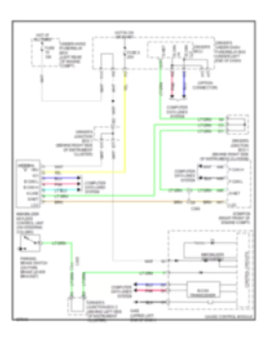
Immobilizer Wiring Diagram for Acura TL 2014
List of elements for Immobilizer Wiring Diagram for Acura TL 2014:
- (option connector)
- (upper left end of dash)
- A41
- A46
- A48
- A49
- Antenna
- B-can h
- B-can l
- B-can transceiver
- C306
- C405
- Computer data lines system
- Control circuits
- Driver's junction box 1 (behind right side of instrument cluster)
- Driver's junction box 2 (behind left side of instrument cluster)
- Driver's micu
- Driver's under-dash fuse/relay box (under left end of dash)
- Ecm/pcm (right front of engine compt)
- F-can h
- F-can l
- F11
- Fuse 10a
- Fuse 9 20a
- G402
- Gauge control module
- Hi b-can
- Hot at all times
- Hot in on or start
- Ig1
- Immobilizer keyless control unit (on steering column)
- Immobilizer system ind
- K-line
- Lg3
- Lo b-can
- Parking brake switch (on park brake lever bracket)
- Pnk
- Q15
- S-net
- Under-hood fuse/relay box (left rear of engine compt)
- Vbu
BODY CONTROL MODULES
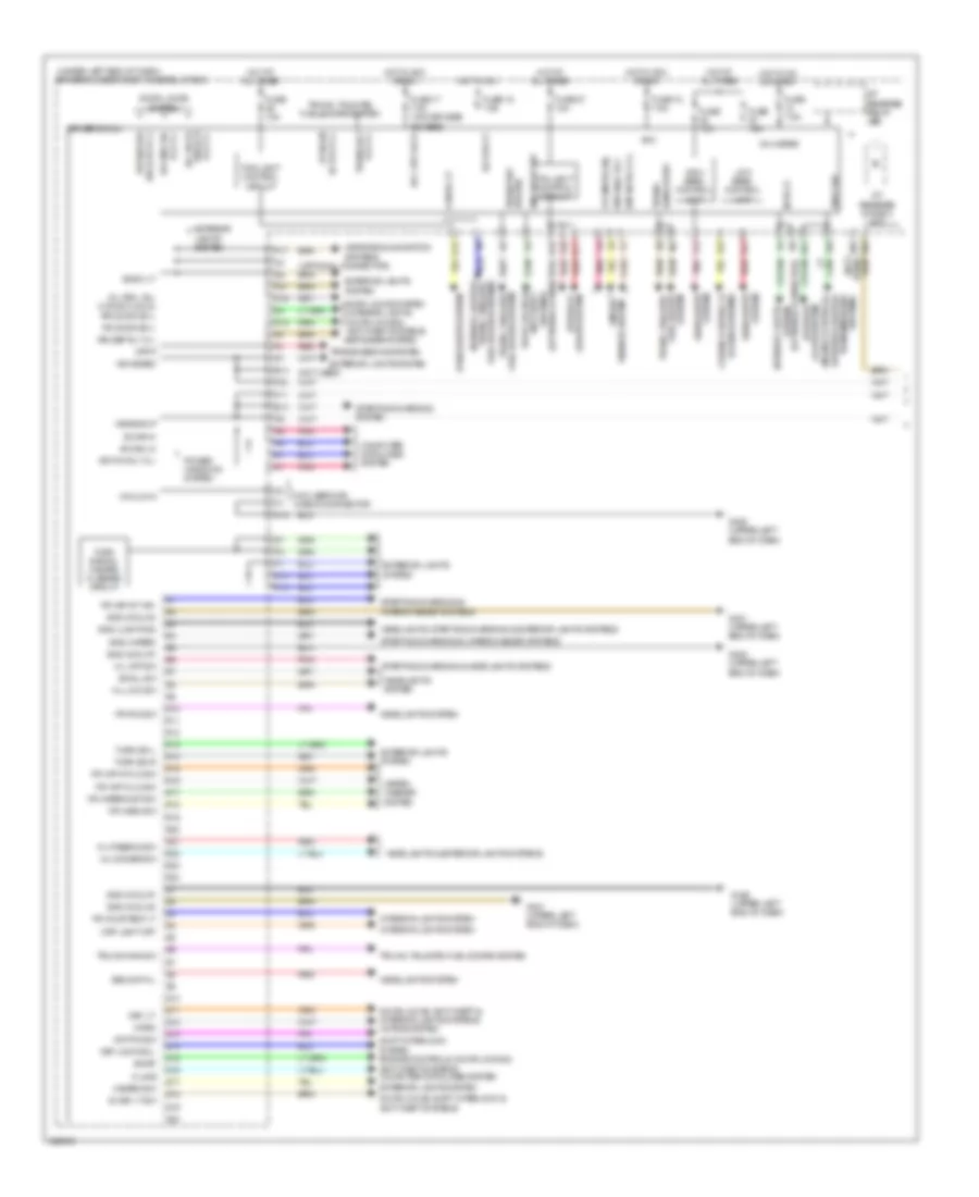
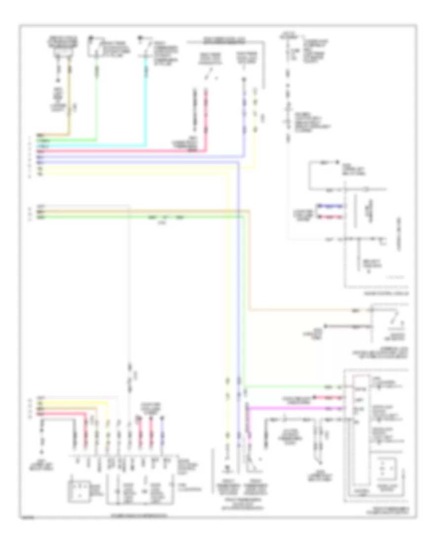
Body Control Modules Wiring Diagram (1 of 2) for Acura TL 2014
List of elements for Body Control Modules Wiring Diagram (1 of 2) for Acura TL 2014:
- (not used)
- (optional connector)
- (under left end of dash) driver's under-dash fuse/relay box
- +b backup
- +b hazard
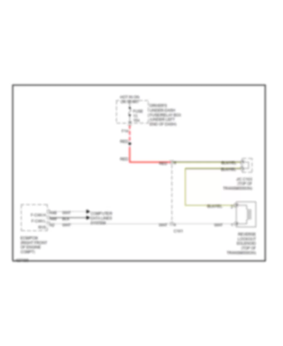
- A/t reverse diode a (a/t)
- A/t reverse relay (a/t)
- Acc
- Acc key lock
- Atp-p
- B-can hi
- B-can-lo
- Back lt-
- Backup h/l
- Cargo lt
- Computer data lines system
- Cruise control & horns systems
- D/l dr fr unlock rly cl-
- D/l rr-l sil- con sw (unlk) rr door sw l
- D11
- D12
- D13
- D15
- Door locks & anti-theft systems
- Door locks system
- Door locks, anti-theft & interior lights systems horns system
- Door locks, shift interlock & anti-theft systems
- Dr p/w rly cl-
- Dr side d/l unlk rly cl-
- Driver's micu
- E12
- E13
- E14
- E20
- Eng hood sw
- Engine controls, exterior lights & transmissions systems
- Exterior lights system
- F10
- F11
- F13
- F20
- F21
- F23
- F27
- F32
- Fog light control circuit
- Fr courtesy lt
- Fr door sw l
- Fr fog sw
- Fr wash sw
- Fr wip hi/lo sw
- Fr wip int vr+
- Fr wip int/lo sw
- Fr wiper (as)
- Fr wiper mist sw
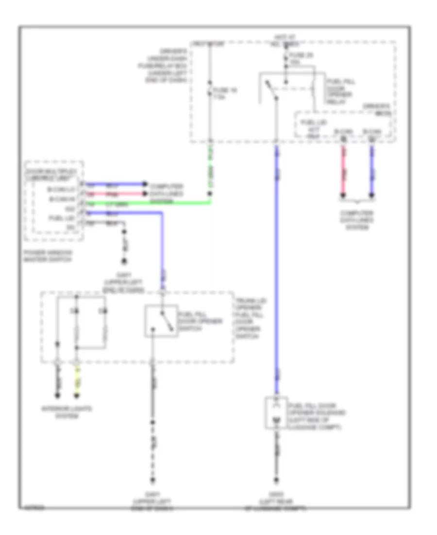
- Fuel doors system trunk, tailgate,
- Fuel/lid act rly cl-
- Fuse 10a
- Fuse 15 7.5a
- Fuse 15a
- Fuse 17 7.5a (w/o keyless access)
- Fuse 18 7.5a
- Fuse 27 10a
- Fuse 7.5a
- G12
- G401 (upper left end of dash)
- G402 (upper left end of dash)
- Gnd (lighting)
- Gnd (micu-p)
- Gnd (micu-s)
- Gnd (wiper)
- H/l dimmer sw
- H/l low sw
- H/l off sw
- H/l passing sw
- H10
- Handle sw trunk
- Hazard sw
- Headlights & exterior lights systems
- Headlights system
- Headlights, starting/charging & exterior lights systems
- High beam control unit
- Horn
- Hot at all times
- Hot in acc or on
- Hot in on
- Hot in on or start
- Ig key lt sw
- Ig p-pin sw
- Ig1 meter
- Ig2 day lt
- Interior lights & trunk, tailgate, fuel doors systems
- Interior lights system
- Interior lights, door locks & anti-theft systems defogger system
- Intr lt-
- K-line
- Key lock sol-
- Key lt-
- Lights system exterior
- Low beam control unit
- Map light off
- Micu chk
- Micu service check connector
- Mirrors & navigation systems
- N12
- P14
- P17
- P20
- Pnk
- Power windows system
- Q10
- Q11
- Q12
- Q13
- Q14
- Q15
- Q16
- Q17
- Q18
- Q19
- Q20
- R10
- R11
- R12
- R13
- R14
- R15
- R16
- R17
- R18
- R19
- R20
- R21
- R22
- R23
- R24
- Red
- Rly cl- dr side d/l
- Rr def rly cl-
- S-net
- Shift interlock system engine controls, door locks & anti-theft systems computer data lines system
- Small sw
- Starting/charging & headlights systems
- Starting/charging & wiper/washer systems
- Starting/charging system
- Stop sw
- System interior lights
- Taillight control circuit
- Transmissions system
- Trunk act rly cl-
- Trunk main sw
- Trunk sw (tig sw)
- Trunk, tailgate, fuel doors system
- Turn signal/ hazard flasher circuit
- Turn sw l
- Turn sw r
- Wip hi/lo rly
- Wip int rly cl-
- Wiper/ washer system
Body Control Modules Wiring Diagram (2 of 2) for Acura TL 2014
List of elements for Body Control Modules Wiring Diagram (2 of 2) for Acura TL 2014:
- (behind right side of nstrument cluster) driver's junction box 1
- (not used)
- +b backup
- +b rr fog
- A11
- A13
- A14
- A17
- A24
- A25
- A29
- A33
- A35
- A36
- A37
- As p/w rly cl-
- Auto lt sig
- Auto lt sio
- Auto lt sip
- B-can hi
- B-can lo
- Backup h/l
- Computer data lines system
- D/l as lock rly cl
- D/l as unlock rly cl
- D/l sil-con rr-r (unlock)
- D10
- D11
- D13
- D14
- D19
- D20
- D22
- Door locks & interior lights systems
- Door locks system
- E10
- E12
- E13
- E15
- E16
- Exterior lights system
- Fog light control circuit
- Fr door sw r
- Fr wash rly cl-
- Fuse (not used)
- Fuse 10a
- Fuse 15 10a
- Fuse 15a
- Fuse 7.5a
- Fuse 9 15a
- G10
- G14
- G15
- G203 (right end of dash)
- G401 (upper left end of dash)
- G405 (upper right end of dash)
- Gnd (micu-p) 1
- Gnd (micu-p) 2
- Gnd (micu-s) 1
- Gnd (micu-s) 2
- H/l wash rly
- H/l wash sw
- H10
- H18
- H22
- H25
- H36
- Headlights & exterior lights systems
- Headlights system
- High beam control unit
- Hot at all times
- Ig1 meter
- Instrument cluster system
- Interior lights system
- Keyless buzzer
- Low beam control unit
- Navigation & sound systems
- Passenger's micu
- Passenger's under-dash fuse/relay box (behind right kick panel)
- Pnk
- Power distribution system
- Power windows system
- Red
- Rf courtesy r
- Rr door sw r
- Scty
- Sound & navigation systems
- Taillight control circuit
- Under-hood fuse/relay box (left rear of engine compt)
- W/ sh-awd
- W/o sh-awd
- Wiper/washer system
COMPUTER DATA LINES
Computer Data Lines Wiring Diagram (1 of 3) for Acura TL 2014
List of elements for Computer Data Lines Wiring Diagram (1 of 3) for Acura TL 2014:
- (behind right kick panel) passenger's under-dash fuse/relay box
- (not used)
- A10
- A11
- A18
- A19
- A20
- A29
- Acuralink control unit (xm receiver) (if equipped) (middle of dash)
- Acuralink re programming connector
- Audio navigation unit (if equipped)
- B-can hi
- B-can lo
- B11
- C16
- C17
- C21
- C306
- C34
- C35
- C406
- C410
- C411
- C501
- Can hi b-
- Can hi f-
- Can lo b-
- Can lo f-
- Center junction box (behind right side of instrument cluster)
- Climate control unit (right side of dash)
- D10
- D11
- D13
- D14
- D25
- D26
- Diag h
- Dlc (under left end of dash)
- Driver's junction box 2 (behind left side of instrument cluster)
- F-can hi
- F-can lo
- Fuse 15 10a
- G401 (upper left end dash)
- G402 (upper left end dash)
- H10
- H11
- H12
- H13
- H14
- H25
- H29
- Handsfreelink control unit (w/o navigation) (under right front of center console)
- Hot at all times
- J/c c204 (right side of dash)
- J/c c506 (upper right side of dash)
- J/c c651 (w/ sh-awd) (right "c" pillar)
- K-line
- Keyless access control unit (under left end of dash)
- Keyless access junction box (under left end of dash)
- Passenger's micu
- Pnk
- Power control unit (left end of dash)
- Red
- Remote slot control unit (right end of dash)
- Scs
- Sh-awd control unit (if equipped) (right side of luggage compt)
- Under-hood fuse/relay box (left rear of engine compt)
- Used) (not
- W/ keyless access
- W/ navigation
- W/ sh- awd
- W/o navigation
- Wen
Computer Data Lines Wiring Diagram (2 of 3) for Acura TL 2014
List of elements for Computer Data Lines Wiring Diagram (2 of 3) for Acura TL 2014:
- (not used)
- (upper left end of dash) g402
- A/t w/ ventilated seats
- A32
- A48
- A49
- B-can hi
- B-can lo
- B39 b-can
- B40 b-can hi
- Bsi control unit (if equipped) (left side of luggage compt)
- C306
- C401
- C404
- C701
- Driver's junction box 1 (behind right side of instrument cluster)
- Driver's micu
- Driver's under-dash fuse/relay box (under left end of dash)
- E10
- E18
- E19
- Ecm/pcm (right front of engine compt)
- Ecs
- Except a/t w/ ventilated seats
- F can h
- F can l
- F24
- F25
- G10
- Hi b-can
- Immobilizer lo b-can
- K-line
- Keyless access junction box (under left end of dash)
- Keyless control unit (on steering column)
- Lo power seat control unit (under driver's seat)
- Micu chk
- Micu service check connector
- N12
- P15
- P16
- Pnk
- Q16
- Red
- Remote starting control unit
- Scs
- W/ keyless access
- W/o keyless access
Computer Data Lines Wiring Diagram (3 of 3) for Acura TL 2014
List of elements for Computer Data Lines Wiring Diagram (3 of 3) for Acura TL 2014:
- (on steering column) (w/ sh-awd) steering angle sensor
- A16
- A17
- A18
- Audio unit (w/o navigation) audio navigation unit (w/ navigation)
- B-can hi
- B-can lo
- C206
- C402
- C406
- C451
- C751
- C752
- C753
- C761
- Center junction box (behind right side of instrument cluster)
- D12
- D15
- D17
- D18
- D28
- Door multiplex control unit
- Driver's junction box 2 (behind left side of instrument cluster)
- E10
- Eps control unit (right end of dash)
- F-can hi
- F-can lo
- Front passenger's power window switch
- G10
- Gauge control module
- J/c c204 (right side of dash)
- K-line
- Moonroof control unit/motor (behind middle of moonroof assembly)
- Pnk
- Power window master switch
- Red
- Scs
- Srs unit (under front of center console)
- Tpms control unit (lower left center of dash)
- Uart
- Vsa modulator control unit (right side of engine compt)
- W/ navigation
- W/o navigation
- Wen
- Yaw rate-lateral acceleration sensor (w/o sh-awd) yaw rate-lateral longitudinal acceleration sensor (w/ sh-awd) (under front of center console)
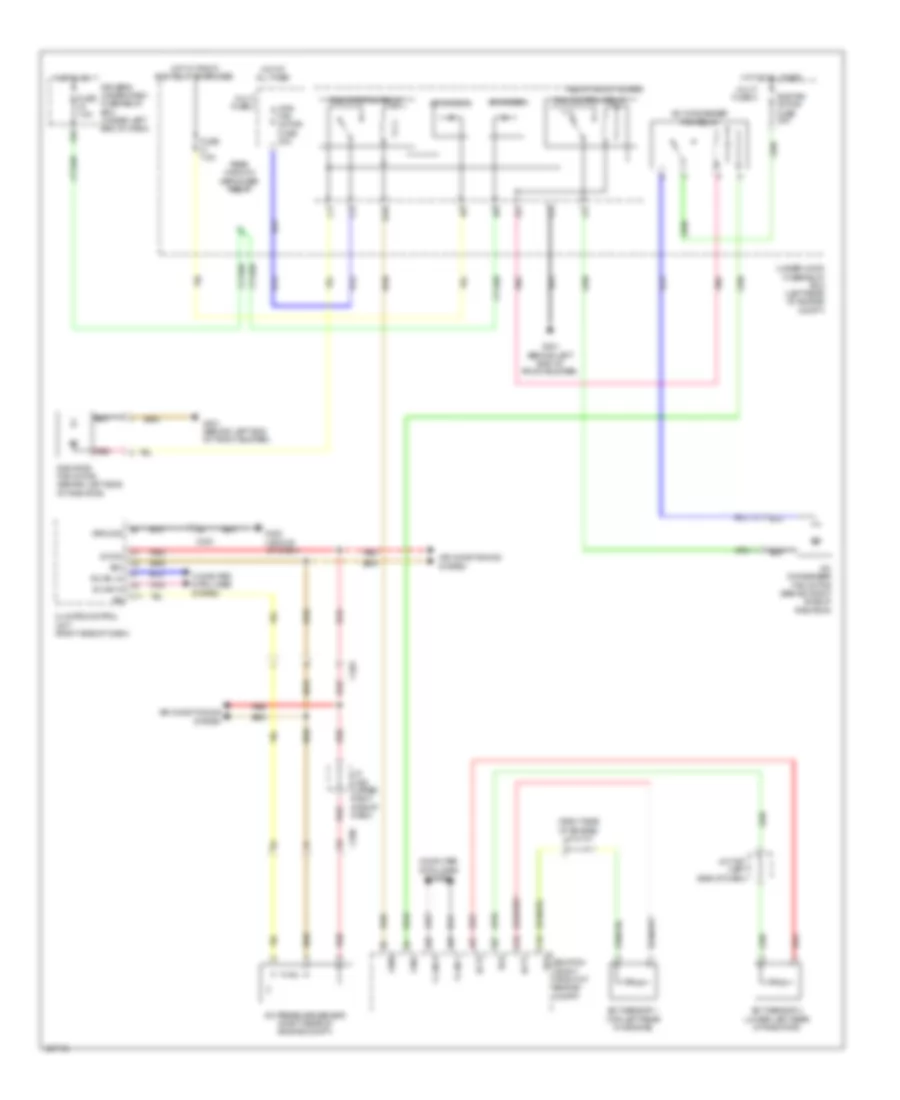
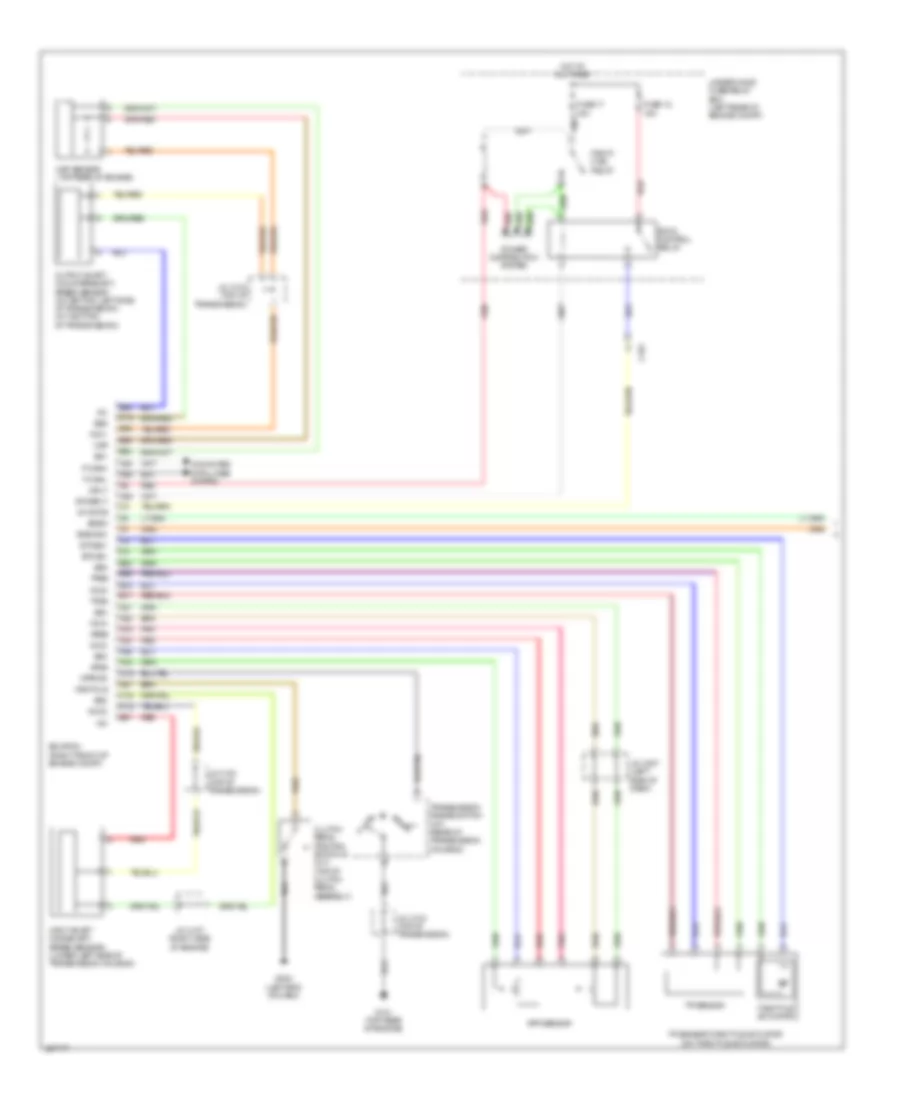
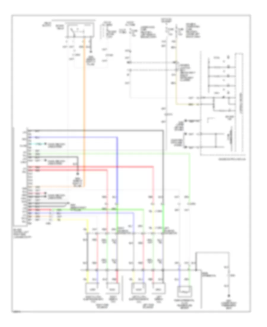
COOLING FAN
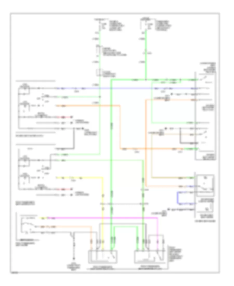
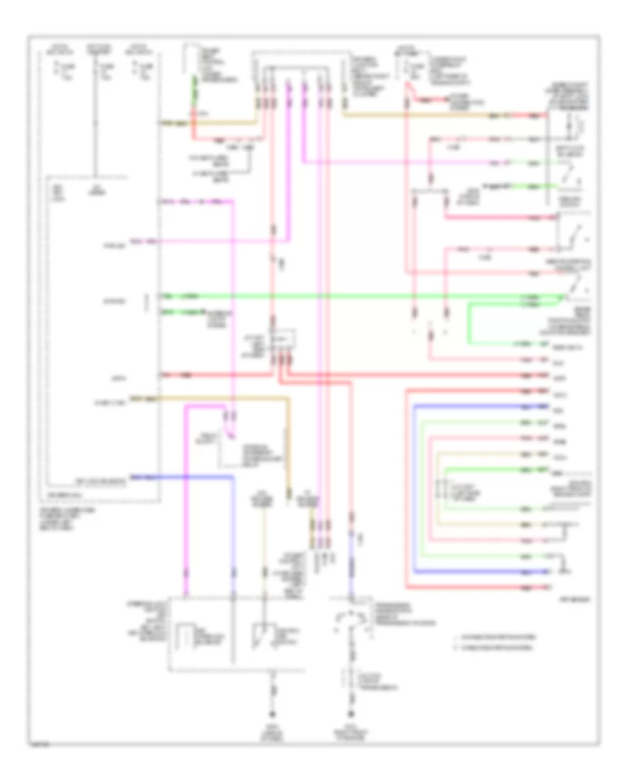
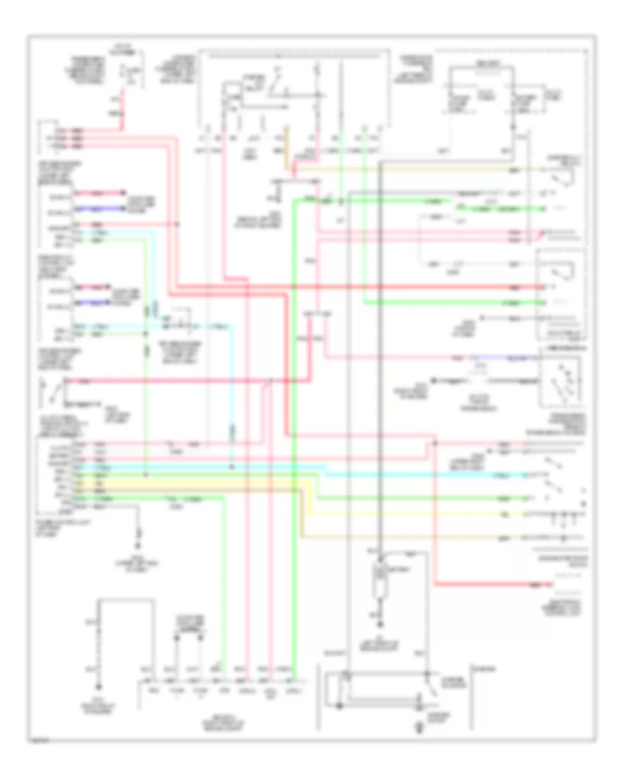
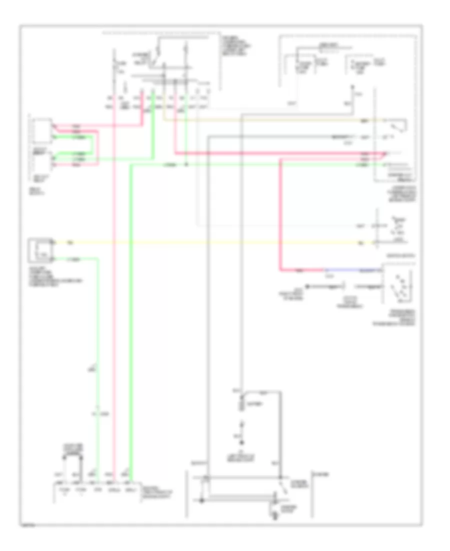
Cooling Fan Wiring Diagram for Acura TL 2014
List of elements for Cooling Fan Wiring Diagram for Acura TL 2014:
- (right side of engine) j/c c107
- A/c condenser fan motor (behind right side of radiator)
- A/c condenser fan relay
- A/c diode a
- A/c diode b
- A/c pressure sensor (right rear of engine compt)
- A1 ground
- A21
- A27
- A48
- A49
- Air conditioning system
- B10
- C1 s-com
- C11 pd
- C16
- C2 s5v
- C206
- C32
- C403
- C7 b can lo
- C8 b can hi
- Climate control unit (right side of dash)
- Computer data lines system
- Driver's under-dash fuse/relay box (under left end of dash)
- Ecm/pcm (right front of engine compt)
- Ect sensor 1 (top left rear of engine)
- Ect sensor 2 (lower left rear of radiator)
- Ect1
- Ect2
- F can h
- F can l
- F26
- Fan control relay
- Fanh
- Fanl
- Fuse 7.5a
- G301 (behind left end of front bumper)
- G403 (middle of dash)
- Hot at all times
- Hot in on
- Hot w/ pgm-fi sub relay energized
- J/c c307 (left side of dash)
- J/c c408 (upper right side of dash)
- Main fan motor fuse 30a
- Multi fuse 3
- Multi fuse-3
- Pnk
- Radiator fan motor (behind left side of radiator)
- Radiator fan relay
- Rear window defogger relay
- Red
- Relay circuit board
- Sg2
- Sg4
- Sub fan motor fuse 30a
- Under-hood fuse/relay box (left rear of engine compt)
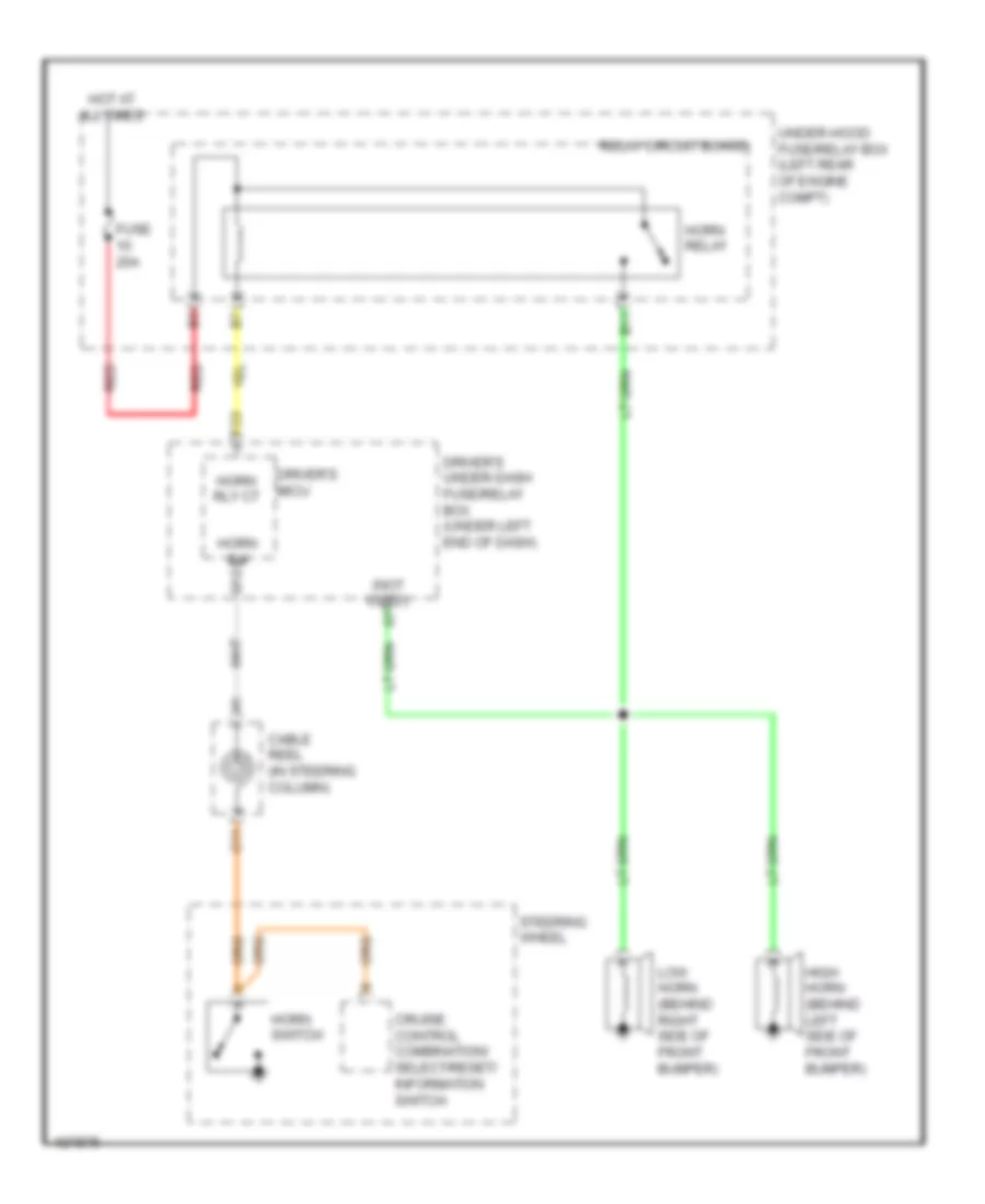
CRUISE CONTROL
Cruise Control Wiring Diagram (1 of 2) for Acura TL 2014
List of elements for Cruise Control Wiring Diagram (1 of 2) for Acura TL 2014:
- A18
- A19
- A24
- A25
- A26
- A27
- A29
- A47
- A48
- A49
- App sensor
- Apsa
- Apsb
- Atpfwd
- B17
- B18
- B26
- B33
- B34
- B35
- B36
- B37
- B38
- Bksw
- Bkswnc
- C101
- C12
- C15
- C16
- C18
- Clutch pedal position switch b (m/t) (top of clutch pedal assembly)
- Computer data lines system
- Crmtcls
- Ecm/pcm (right front of engine compt)
- Etcs control relay
- Etcsm+
- Etcsm-
- Etcsrly
- F-canh
- F-canl
- Fuse 17 15a
- Fuse 18 15a
- G101 (top rear of engine)
- G302 (left end of dash)
- Hot at all times
- Ig1 etcs
- Input shaft (mainshaft) speed sensor) (lower left side of transmission housing)
- J/c c103 (top of transmission)
- J/c c107 (right side of engine)
- J/c c307 (left side of dash)
- Map
- Map sensor (top rear of engine)
- Mrly
- Ncc2
- Output shaft (countershaft) speed sensor (a/t: bottom left side of transmission) (m/t: bottom of transmission)
- Pgm-fi main relay
- Pnk
- Power distribution system
- Red
- Sg1
- Sg2
- Sg3
- Sg4
- Sg5
- Sg6
- Throttle actuator
- Tp sensor
- Tp sensor/throttle actuator (on throttle actuator)
- Tpsa
- Tpsb
- Transmission range switch (a/t) (rear of transmission housing)
- Under-hood fuse/relay box (left rear of engine compt)
- Vcc1
- Vcc3
- Vcc4
- Vcc5
Cruise Control Wiring Diagram (2 of 2) for Acura TL 2014
List of elements for Cruise Control Wiring Diagram (2 of 2) for Acura TL 2014:
- A13
- A14
- B11
- Brake pedal position switch (on brake pedal mounting bracket)
- C11
- C12
- C13
- C14
- Cable reel (in steering column)
- Cancel switch
- Computer data lines system
- Control circuits
- Cruise control combination/select/reset information switch
- Cruise control ind
- Cruise control main switch
- Cruise control main switch ind
- Driver's junction box 1 (behind right side of instrument cluster)
- Driver's micu
- Driver's under-dash fuse/relay box (under left end of dash)
- E10
- Exterior lights system
- F14
- F23
- Fast controller area network
- Fuse 10a
- Fuse 12 7.5a
- Fuse 15a
- Fuse 20a
- G401 (upper left end of dash)
- G405 (upper right end of dash)
- Gauge control module (rear of instrument cluster)
- Horn relay
- Horn switch
- Horns system
- Hot at all times
- Hot in on or start
- Hrn rly cl-
- Hrn sw q12
- Indicator dimming circuit
- Interior lights system
- Next switch
- P20
- Red
- Relay circuit board
- Resume/ accel switch
- Select/ reset switch
- Set/ decel switch
- Steering wheel
- Transceiver
- Transmissions system
- Under-hood fuse/relay box (left rear of engine compt)
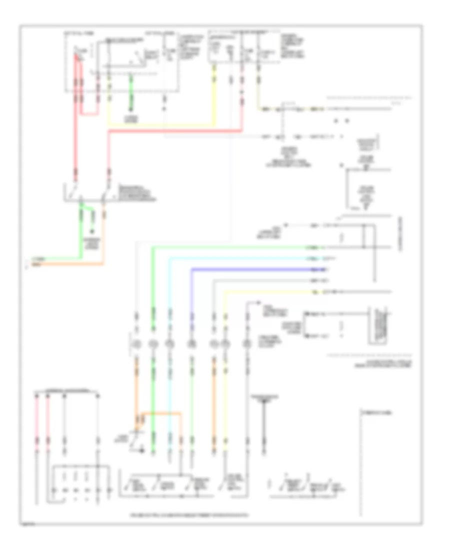
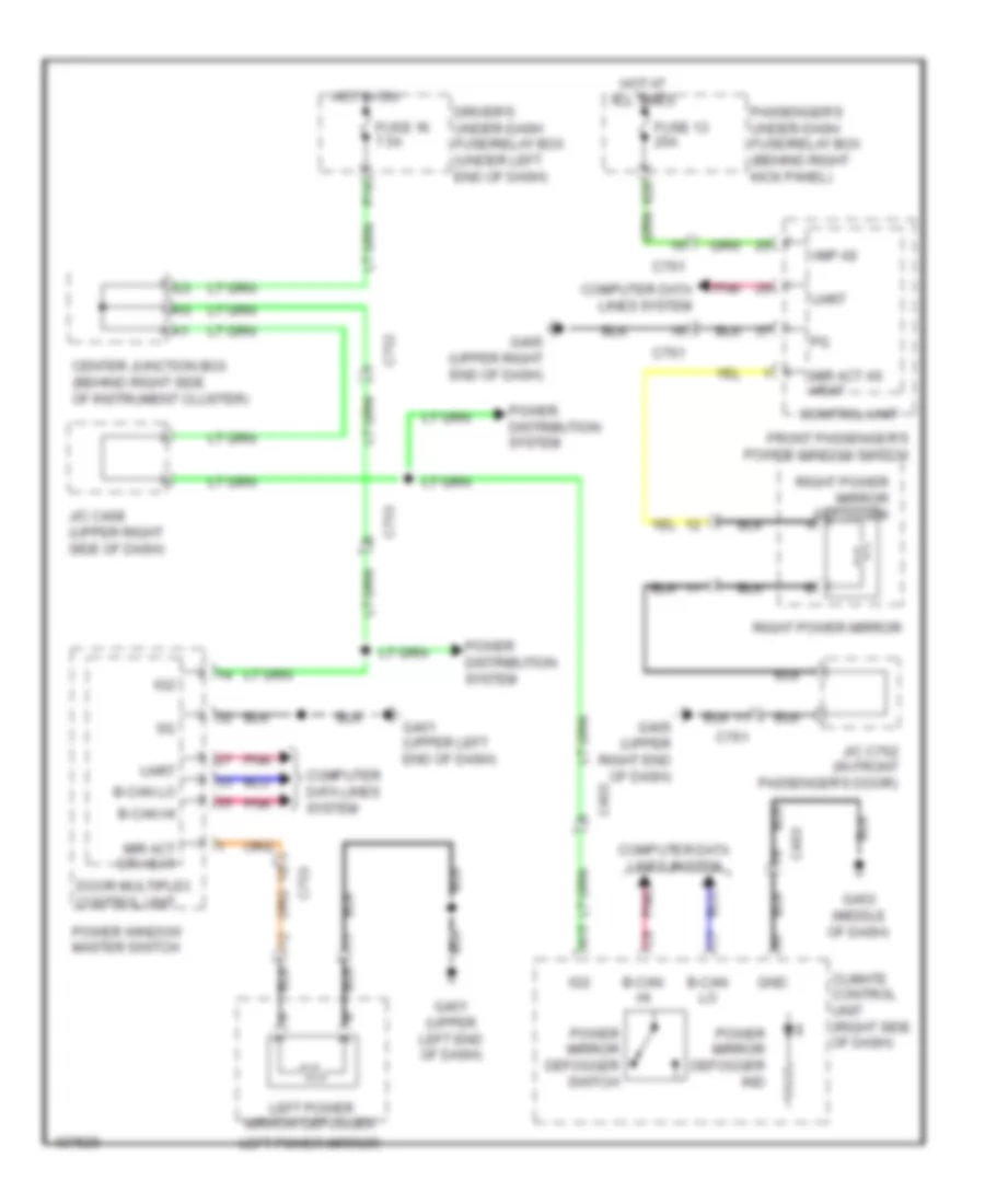
DEFOGGERS
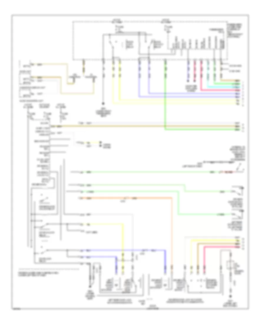
Heated Mirrors Wiring Diagram for Acura TL 2014
List of elements for Heated Mirrors Wiring Diagram for Acura TL 2014:
- A15
- A28
- B-can hi
- B-can lo
- C403
- C752
- C753
- C761
- Center junction box (behind right side of instrument cluster)
- Climate control unit (right side of dash)
- Computer data lines system
- Control unit
- Door multiplex control unit
- Driver's under-dash fuse/relay box (under left end of dash)
- Front passenger's power window switch
- Fuse 13 20a
- Fuse 16 7.5a
- G401 (upper left end of dash)
- G403 (middle of dash)
- G405 (upper right end of dash)
- Gnd
- Hot at all times
- Hot in on
- Ig2
- J/c c408 (upper right side of dash)
- J/c c762 (in front passenger's door)
- Left power mirror
- Left power mirror defogger
- Mir act as heat
- Mir act dr heat
- P18
- Passenger's under-dash fuse/relay box (behind right kick panel)
- Pnk
- Power distribution system
- Power mirror defogger ind
- Power mirror defogger switch
- Power window master switch
- Right power mirror
- Right power mirror defogger
- Uart
- Vmp as
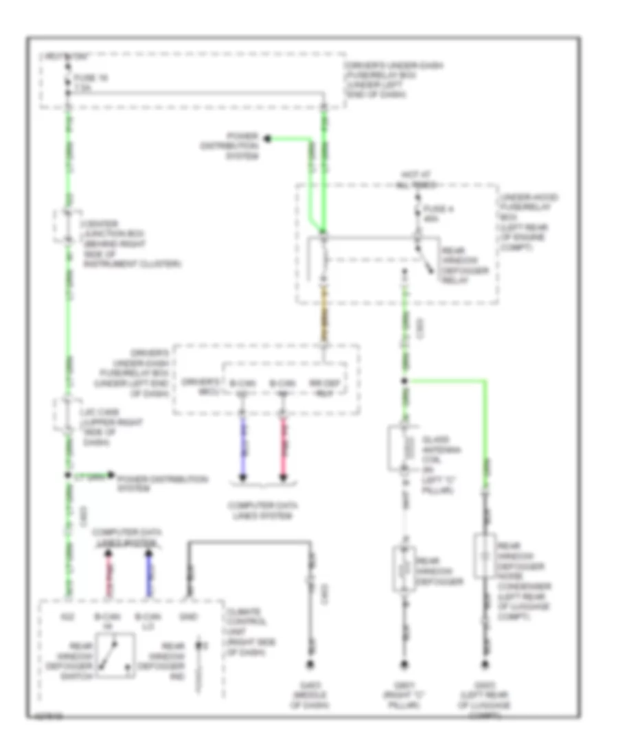
Rear Defogger Wiring Diagram for Acura TL 2014
List of elements for Rear Defogger Wiring Diagram for Acura TL 2014:
- A15
- B-can hi
- B-can lo
- C303
- C403
- Center junction box (behind right side of instrument cluster)
- Climate control unit (right side of dash)
- Computer data lines system
- Driver's micu
- Driver's under-dash fuse/relay box (under left end of dash)
- F26
- Fuse 16 7.5a
- Fuse 4 40a
- G403 (middle of dash)
- G603 (left rear of luggage compt)
- G801 (right "c" pillar)
- Glass antenna coil (in left "c" pillar)
- Gnd
- Hot at all times
- Hot in on
- Ig2
- J/c c408 (upper right side of dash)
- P18
- Pnk
- Power distribution system
- Rear window defogger
- Rear window defogger ind
- Rear window defogger noise condenser (left rear of luggage compt)
- Rear window defogger relay
- Rear window defogger switch
- Rr def rly
- Under-hood fuse/relay box (left rear of engine compt)
ELECTRONIC POWER STEERING
Electronic Power Steering Wiring Diagram for Acura TL 2014
List of elements for Electronic Power Steering Wiring Diagram for Acura TL 2014:
- (under front of center console) (w/ sh-awd) yaw rate lateral/ longitudinal acceleration sensor (w/o sh-awd) yaw rate lateral acceleration sensor
- A22
- A33
- Batt in (b+)
- C202
- C203
- C205
- C206
- C302
- C306
- Can-h
- Can-l
- Center junction box (behind right side of instrument cluster)
- Computer data lines system
- Control circuits
- Controller area network
- D10
- D11
- D12
- D13
- D14
- D15
- D16
- D17
- D18
- D19
- D20
- D21
- D22
- D23
- D24
- D25
- D26
- D27
- D28
- Driver's junction box 1 (behind right side of instrument cluster)
- Driver's under-dash fuse/relay box (under left end of dash)
- E10
- Ecm/pcm (right front of engine compt)
- Eps control unit (right end of dash)
- Eps fuse 70a
- Eps ind
- Eps motor
- Eps motor angle sensor
- Eps torque sensor
- Fast
- Fuse 12 7.5a
- Fuse 6 7.5a
- G203 (right rear of engine compt)
- G204 (right end of dash)
- G401 (upper left end of dash)
- Gauge control module (rear of instrument cluster)
- Hot at all times
- Hot in on or start
- Ig1
- K-line
- Multi- fuse 2
- Nep
- P20
- Passenger's under-dash fuse/relay box (behind right kick panel)
- Pnk
- Pvf
- Red
- Scs
- Steering angle sensor (w/ sh-awd) (on steering column)
- Steering gearbox
- Transceiver
- Under-hood fuse/relay box (left rear of engine compt)
- Vs1
- Vs2
- Vsa modulator control unit (right side of engine compt)
ENGINE PERFORMANCE
3.5L
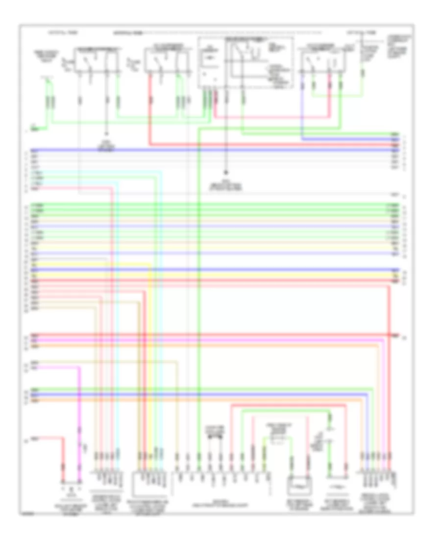
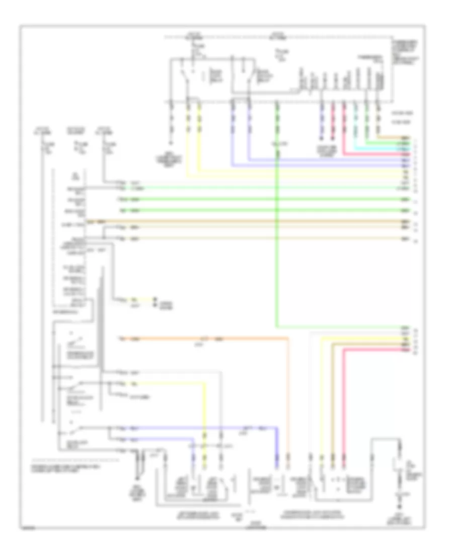
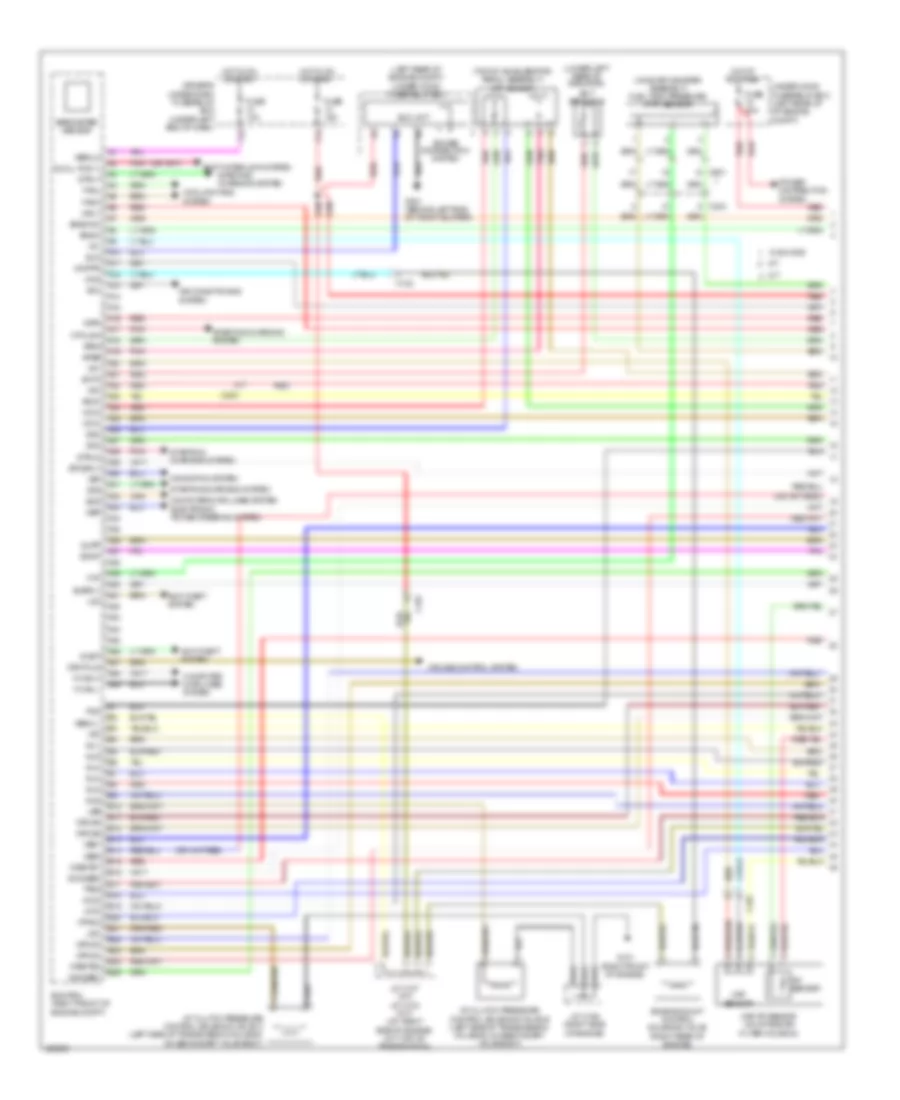
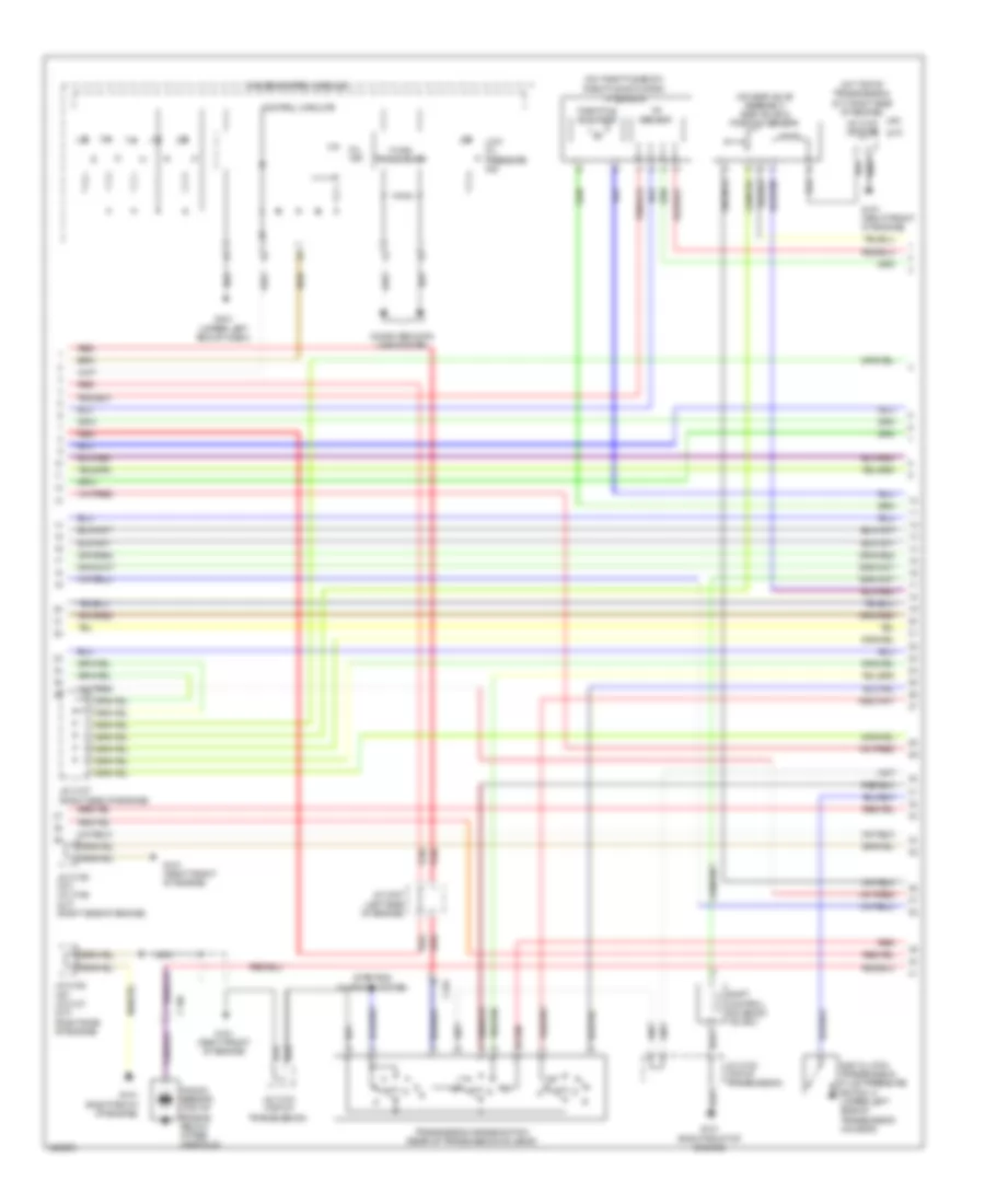
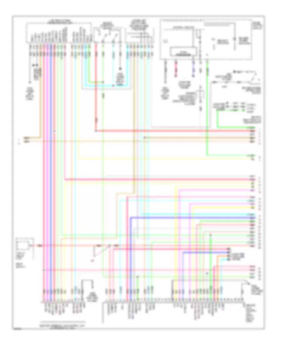
3.5L, Engine Performance Wiring Diagram (1 of 6) for Acura TL 2014
List of elements for 3.5L, Engine Performance Wiring Diagram (1 of 6) for Acura TL 2014:
- (left rear of engine compt) under-hood fuse/relay box
- (lower left rear of radiator)
- (on evap canister assembly) fuel tank pressure (ftp) sensor
- (top of accelerator pedal assembly) app sensor
- A/t
- A/t clutch pressure control solenoid valve b (left side of transmission housing, on secondary valve body)
- A/t clutch pressure control solenoid valve c (left side of transmission housing, on secondary valve body)
- A10
- A11
- A12
- A13
- A14
- A15
- A16
- A17
- A18
- A19
- A20
- A21
- A22
- A23
- A24
- A25
- A26
- A27
- A28
- A29
- A30
- A31
- A32
- A33
- A34
- A35
- A36
- A37
- A38
- A39
- A40
- A41
- A42
- A43
- A44
- A45
- A46
- A47
- A48
- A49
- Acc
- Air conditioning system
- Anti-theft system
- Apsa
- Apsb
- Atpp
- B10
- B11
- B12
- B13
- B14
- B15
- B16
- B17
- B18
- B19
- B20
- B21
- B22
- B23
- B24
- B25
- Barometer sensor
- Bksw
- Bkswnc
- C101
- C102
- C303
- C601
- Computer data lines system
- Computer data lines system electronic power steering system
- Cooling fans system
- Crmtcls
- Cruise control system
- Driver's under-dash fuse/relay box (under left end of dash)
- Ecm/pcm (right front of engine compt)
- Ect sensor 2
- Ect2
- Eld
- Eld unit
- Engine mount control solenoid valve (right rear of engine)
- Etcsrly
- F-can h
- F-can l
- F12
- F14
- Fanh
- Fanl
- Ftp
- Fuse 10a
- Fuse 15a
- Fuse 20a
- G101 (right front of engine)
- G301 (behind left end of front bumper)
- Hot at all times
- Hot in on or start
- Iat sensor
- Igp
- Igpls3
- Igpls4
- Igpls5
- Igpls6
- Imofpr
- Imtm
- Inj1
- Inj2
- Inj3
- Inj4
- Inj5
- Inj6
- J/c c106 (right side of engine)
- J/c c107 (a/t) j/c c103 (m/t) (a/t: right side of engine) (m/t: top of transmission)
- Lg3
- Lsb
- Lsc
- M/t
- Maf sensor
- Maf/iat sensor (on intake air filter housing)
- Mcs
- Mrly
- Mtclsw
- Navigation system
- Nep
- Pg2
- Pnk
- Power distribution system
- Red
- Rvs
- S net
- Scs
- Sdnp
- Sg3
- Sg4
- Sh02sb1
- Shift interlock system
- Sho2sb2
- Sls
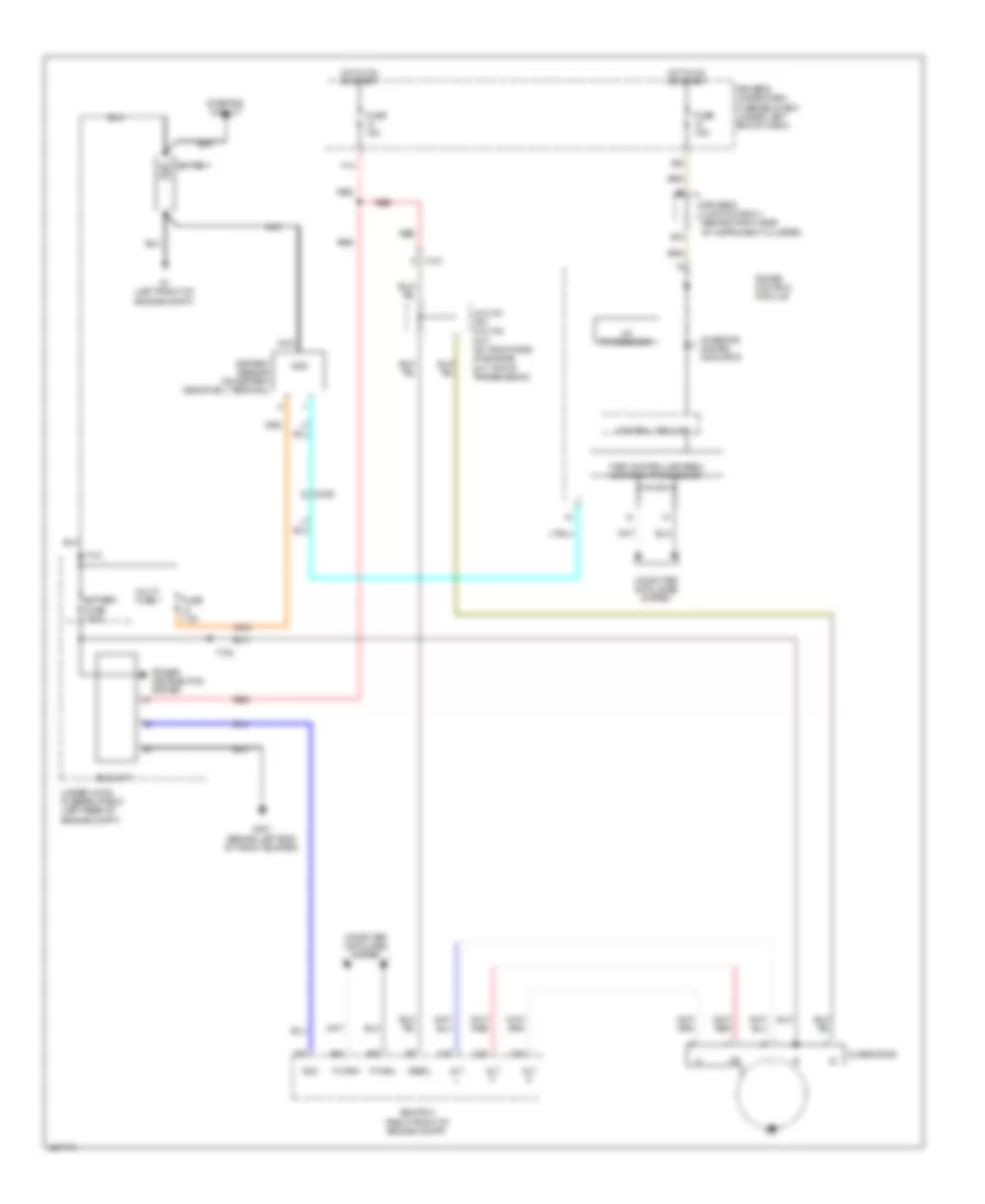
- Starting/ charging system
- Starting/charging system
- Strld
- Strly
- Sts
- Subrly
- Supp
- Tpsa
- Under-hood fuse/relay box (left rear of of engine compt)
- Vbsol1
- Vbsol2
- Vbum
- Vcc3
- Vcc4
- Vcc5
- Vcentb1
- Vcentb2
- Vg+
- Vg-
- Vsb1
- Vsb2
- Vsp
- Vsv
- Vtpsw
- W/ sh-awd
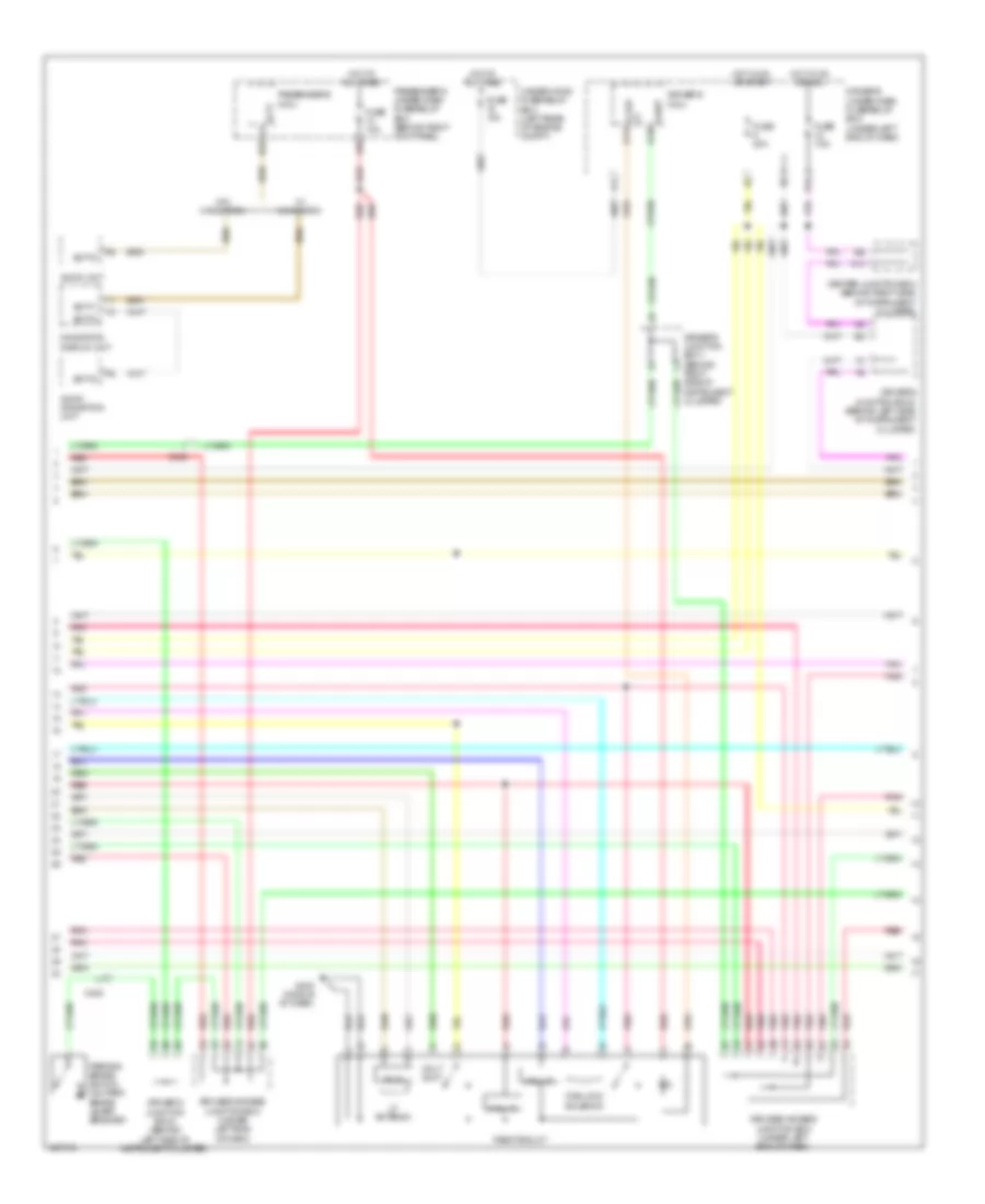
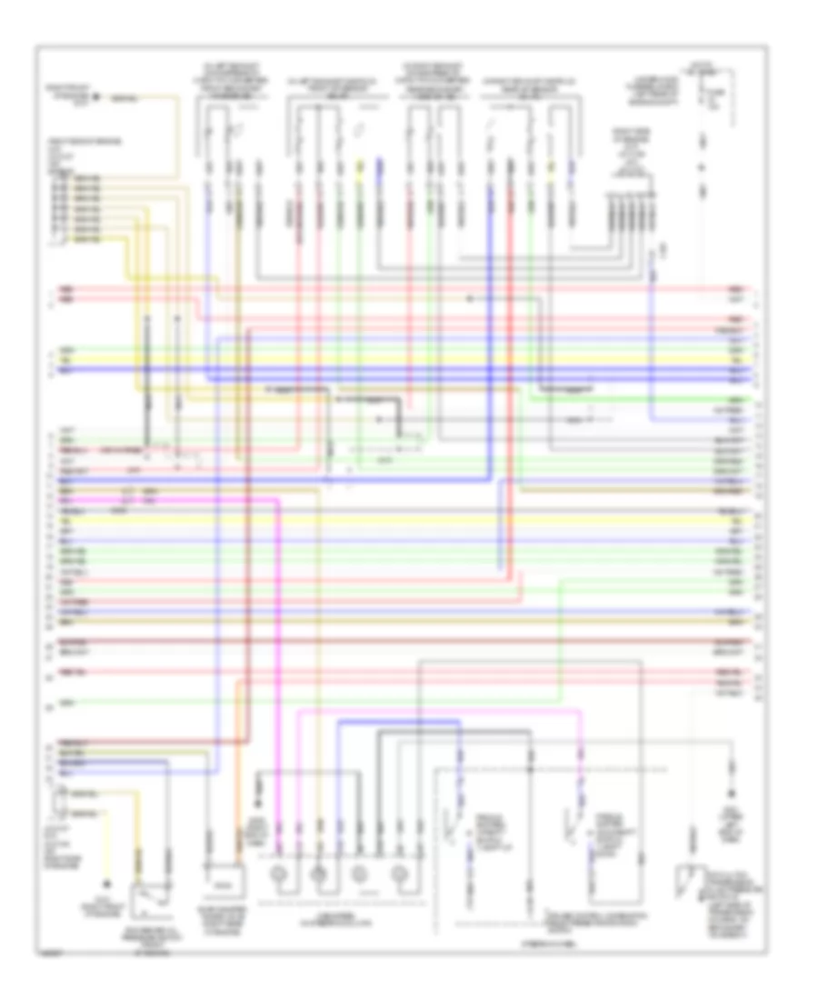
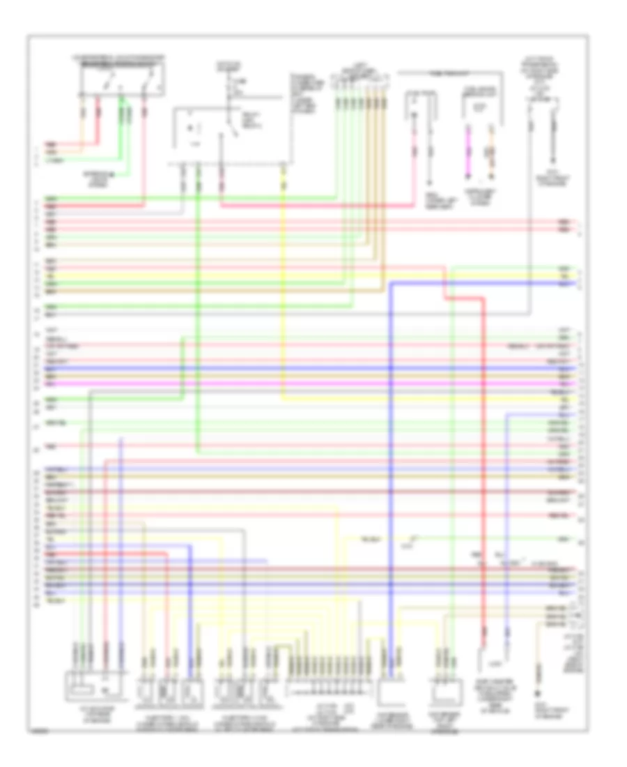
3.5L, Engine Performance Wiring Diagram (2 of 6) for Acura TL 2014
List of elements for 3.5L, Engine Performance Wiring Diagram (2 of 6) for Acura TL 2014:
- (a/t) (m/t)
- (left side of dash) j/c c307
- (m/t: top of transmission) (a/t: right side of engine) (m/t) j/c c103 (a/t) j/c c106
- (on brake pedal mounting bracket) brake pedal position switch
- (right front of engine)
- C101
- C601
- Ckp sensor (lower right rear of engine)
- Cmp sensor (top left front of engine)
- D10
- Driver's under-dash fuse/relay box (under left end of dash)
- Evap canister vent shut valve (if equipped) (under right rear of vehicle)
- Exterior lights system
- F22
- F31
- Fuel gauge sending unit
- Fuel pump
- Fuel tank unit
- Fuse 20a
- G101
- G101 (right front of engine)
- G602 (under left rear seat)
- Hot in on or start
- Imt actuator (top rear of engine)
- Injectors 1, 2 & 3 (under intake manifold in right cylinder bank)
- Injectors 4, 5 & 6 (under intake manifold in left cylinder bank)
- Instrument cluster system
- J/c c105 (m/t) j/c c106 (a/t) (right side of engine)
- J/c c106 j/c c103 (a/t: right side of engine) (m/t: top of transmission)
- Pgm-f1 main relay 2
- Pnk
- Red
- W/ sh-awd
3.5L, Engine Performance Wiring Diagram (3 of 6) for Acura TL 2014
List of elements for 3.5L, Engine Performance Wiring Diagram (3 of 6) for Acura TL 2014:
- (a/t)
- (in left exhaust manifold)
- (in left exhaust, downstream of catalytic converter) front secondary ho2s (b2, s2)
- (in right exhaust manifold) rear a/f sensor (b1, s1)
- (in right exhaust, downstream of catalytic converter)
- (m/t)
- (right front of engine) g101
- (right side of engine) (m/t) j/c c106 (a/t) j/c c107
- (right side of engine) (m/t) j/c c107 (a/t) j/c c105
- 6th clutch transmission fluid pressure switch e (left side of transmission housing, on secondary valve body)
- A15
- A17
- C101
- C12
- C15
- C17
- C306
- Cable reel (in steering column)
- Cruise control combination select/reset/information switch
- Evap canister purge valve (right rear of engine)
- Front a/f sensor (b2, s1)
- Fuse 10a
- G101 (right front of engine)
- G401 (upper left end of dash)
- G405 (right end of dash)
- Hot at all times
- J/c c107 (m/t) j/c c105 (a/t) (right side of engine)
- Nca
- Paddle shifter (downshift
- Paddle shifter+ (upshift
- Rear secondary ho2s (b1, s2)
- Red
- Rocker arm oil pressure switch (front of engine)
- Steering wheel
- Switch) 1) shift down
- Switch) 1) shift up
- Under-hood fuse/relay box (left rear of engine compt)
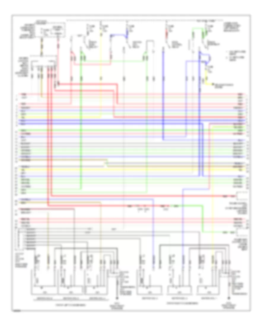
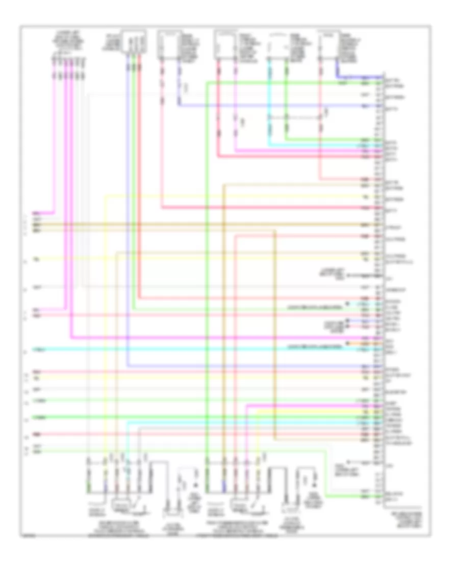
3.5L, Engine Performance Wiring Diagram (4 of 6) for Acura TL 2014
List of elements for 3.5L, Engine Performance Wiring Diagram (4 of 6) for Acura TL 2014:
- (right side of engine)
- (top of left cylinder bank)
- (top of right cylinder bank)
- A16
- Air conditioning system
- Atp-d
- B26
- C101
- C303
- C306
- C404
- C701
- Driver's junction box 1 (behind right side of instrument cluster)
- Driver's misc
- Driver's under-dash fuse/relay box (under left end of dash)
- E10
- Etcs control relay
- Fuse 15a
- Fuse 7.5a
- G101 (right front of engine)
- Hot at all times
- Hot in on or start
- Icm
- Ignition coil 1
- Ignition coil 2
- Ignition coil 3
- Ignition coil 4
- Ignition coil 5
- Ignition coil 6
- Ignition coil relay
- J/c c103 (a/t) j/c c106 (m/t) (a/t: top of transmission) (m/t: right side of engine)
- J/c c106 (a/t) j/c c103 (m/t) (a/t: right side of engine) (m/t: top of transmission)
- J/c c107 (a/t) j/c c106 (m/t)
- P20
- Pgm-fi main relay 1
- Pgm-fi sub-relay
- Power control unit (w/ keyless access) (left end of dash)
- Power seat control unit (under driver's seat)
- Red
- Under-hood fuse/relay box (left rear of engine compt)
- W/ ventilated seats
- W/o ventilated seats
3.5L, Engine Performance Wiring Diagram (5 of 6) for Acura TL 2014
List of elements for 3.5L, Engine Performance Wiring Diagram (5 of 6) for Acura TL 2014:
- (a/t)
- (a/t: top of transmission) (m/t: right side of engine)
- (m/t)
- (on egr valve assembly) egr valve & position sensor
- (on throttle body) throttle actuator/
- 2nd clutch transmission fluid pressure switch a (upper left side of transmission housing)
- C101
- C104
- Computer data lines system
- Control circuits
- F-can transceiver
- G101 (right front of engine)
- G401 (upper left end of dash)
- Gauge control module
- J/c c103 (top of transmission)
- J/c c103 j/c c106
- J/c c105 (a/t) j/c c106 (m/t) (right side of engine)
- J/c c105 (a/t) j/c c107 (m/t) (right side of engine)
- J/c c107 (right side of engine)
- J/c c307 (left side of engine)
- Knock sensor (top of engine, below intake manifold)
- Low oil pressure ind
- Mil ind
- N r
- Nca
- Red
- Shift control solenoid valve c
- Starting/ charging system
- Throttle actuator
- Tp sensor
- Transmission range switch (rear of transmission housing)
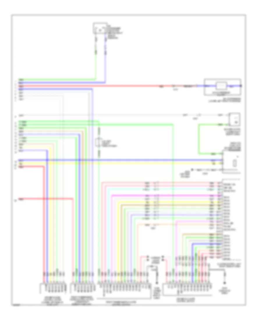
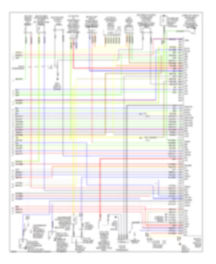
3.5L, Engine Performance Wiring Diagram (6 of 6) for Acura TL 2014
List of elements for 3.5L, Engine Performance Wiring Diagram (6 of 6) for Acura TL 2014:
- (a/t)
- (a/t: top of transmission) (m/t: right side of engine) j/c c103 j/c c107
- (bottom left side of transmission) output shaft (countershaft) speed sensor
- (bottom rear of transmission housing) atf temperature sensor
- (left side of housing, on secondary valve body) a/t clutch pressure control solenoid valve d
- (m/t)
- (m/t: bottom of transmission) (a/t: lower left side of transmission) input shaft (mainshaft) speed sensor
- (top left rear of engine) ect sensor 1
- (top of transmission)
- (top rear of engine) map sensor
- (upper left side of transmission housing) 5th clutch transmission fluid pressure switch d
- 3rd clutch transmission fluid pressure switch b (left side of transmission housing, on secondary valve body)
- 4th clutch transmission fluid pressure switch c (bottom left side of transmission housing)
- A/t clutch pressure control solenoid valve a (left side of transmission housing, on secondary valve body)
- Afshtcb1
- Afshtcb2
- Altc
- Altf
- Altl
- Atpd
- Atpfwd
- Atpn
- Atpr
- Atprvs
- Atps
- B26
- B27
- B28
- B29
- B30
- B31
- B32
- B33
- B34
- B35
- B36
- B37
- B38
- B39
- B40
- B41
- B42
- B43
- B44
- B45
- B46
- B47
- B48
- B49
- C10
- C101
- C11
- C12
- C13
- C14
- C15
- C16
- C17
- C18
- C19
- C20
- C21
- C22
- C23
- C24
- C25
- C26
- C27
- C28
- C29
- C30
- C31
- C32
- C33
- C34
- C35
- C36
- C37
- C38
- C39
- C40
- C41
- C42
- C43
- C44
- C45
- C46
- C47
- C48
- C49
- Ckp
- Cmp
- Ecm/pcm (right front of engine compt)
- Ect1
- Egr
- Egrp
- Engine) g101
- Etcsm+
- Etcsm-
- G101 (right front of engine)
- Iat
- Ig1
- Ig1etcs
- Igpls1
- Igpls2
- Imt+
- Imt-
- Ipb1
- Ipb2
- J/c c103
- J/c c103 (top of transmission)
- J/c c105 j/c c107 (right side of engine)
- J/c c106 (right side of engine)
- Lg1
- Lg2
- Line pressure solenoid valve a (left side of transmission housing, on secondary valve body)
- Line pressure switch (left side of transmission housing, on secondary valve body)
- Lsa
- Lsd
- Map
- Oil pressure switch
- Op2sw
- Op3sw
- Op4sw
- Op5sw
- Op6sw
- Opsw
- Pcs
- Pg1
- Pgmetcs
- Pla
- Red
- Rocker arm oil control solenoid (front of engine)
- S02htcb2
- S02shtcb1
- Sg1
- Sg2
- Sg5
- Sg6
- Sha
- Shb
- Shd
- Shift control solenoid valve a
- Shift control solenoid volve b
- So2sgb1
- So2sgb2
- Starting/ charging system
- Tatf
- Tpsb
- Vcc1
- Vcc2
- Vcc6
- Vts
3.7L
3.7L, Engine Performance Wiring Diagram (1 of 6) for Acura TL 2014
List of elements for 3.7L, Engine Performance Wiring Diagram (1 of 6) for Acura TL 2014:
- (left rear of engine compt) under-hood fuse/relay box
- (lower left rear of radiator)
- (on evap canister assembly) fuel tank pressure (ftp) sensor
- (top of accelerator pedal assembly) app sensor
- A/t
- A/t clutch pressure control solenoid valve b (left side of transmission housing, on secondary valve body)
- A/t clutch pressure control solenoid valve c (left side of transmission housing, on secondary valve body)
- A10
- A11
- A12
- A13
- A14
- A15
- A16
- A17
- A18
- A19
- A20
- A21
- A22
- A23
- A24
- A25
- A26
- A27
- A28
- A29
- A30
- A31
- A32
- A33
- A34
- A35
- A36
- A37
- A38
- A39
- A40
- A41
- A42
- A43
- A44
- A45
- A46
- A47
- A48
- A49
- Acc
- Air conditioning system
- Anti-theft system
- Apsa
- Apsb
- Atpp
- B10
- B11
- B12
- B13
- B14
- B15
- B16
- B17
- B18
- B19
- B20
- B21
- B22
- B23
- B24
- B25
- Barometer sensor
- Bksw
- Bkswnc
- C101
- C102
- C303
- C601
- Computer data lines system
- Computer data lines system electronic power steering system
- Cooling fans system
- Crmtcls
- Cruise control system
- Driver's under-dash fuse/relay box (under left end of dash)
- Ecm/pcm (right front of engine compt)
- Ect sensor 2
- Ect2
- Eld
- Eld unit
- Engine mount control solenoid valve (right rear of engine)
- Etcsrly
- F-can h
- F-can l
- F12
- F14
- Fanh
- Fanl
- Ftp
- Fuse 10a
- Fuse 15a
- Fuse 20a
- G101 (right front of engine)
- G301 (behind left end of front bumper)
- Hot at all times
- Hot in on or start
- Iat sensor
- Igp
- Igpls3
- Igpls4
- Igpls5
- Igpls6
- Imofpr
- Imtm
- Inj1
- Inj2
- Inj3
- Inj4
- Inj5
- Inj6
- J/c c106 (right side of engine)
- J/c c107 (a/t) j/c c103 (m/t) (a/t: right side of engine) (m/t: top of transmission)
- Lg3
- Lsb
- Lsc
- M/t
- Maf sensor
- Maf/iat sensor (on intake air filter housing)
- Mcs
- Mrly
- Mtclsw
- Navigation system
- Nep
- Pg2
- Pnk
- Power distribution system
- Red
- Rvs
- S net
- Scs
- Sdnp
- Sg3
- Sg4
- Sh02sb1
- Shift interlock system
- Sho2sb2
- Sls
- Starting/ charging system
- Starting/charging system
- Strld
- Strly
- Sts
- Subrly
- Supp
- Tpsa
- Under-hood fuse/relay box (left rear of of engine compt)
- Vbsol1
- Vbsol2
- Vbum
- Vcc3
- Vcc4
- Vcc5
- Vcentb1
- Vcentb2
- Vg+
- Vg-
- Vsb1
- Vsb2
- Vsp
- Vsv
- Vtpsw
- W/ sh-awd
3.7L, Engine Performance Wiring Diagram (2 of 6) for Acura TL 2014
List of elements for 3.7L, Engine Performance Wiring Diagram (2 of 6) for Acura TL 2014:
- (a/t) (m/t)
- (left side of dash) j/c c307
- (m/t: top of transmission) (a/t: right side of engine) (m/t) j/c c103 (a/t) j/c c106
- (on brake pedal mounting bracket) brake pedal position switch
- (right front of engine)
- C101
- C601
- Ckp sensor (lower right rear of engine)
- Cmp sensor (top left front of engine)
- D10
- Driver's under-dash fuse/relay box (under left end of dash)
- Evap canister vent shut valve (if equipped) (under right rear of vehicle)
- Exterior lights system
- F22
- F31
- Fuel gauge sending unit
- Fuel pump
- Fuel tank unit
- Fuse 20a
- G101
- G101 (right front of engine)
- G602 (under left rear seat)
- Hot in on or start
- Imt actuator (top rear of engine)
- Injectors 1, 2 & 3 (under intake manifold in right cylinder bank)
- Injectors 4, 5 & 6 (under intake manifold in left cylinder bank)
- Instrument cluster system
- J/c c105 (m/t) j/c c106 (a/t) (right side of engine)
- J/c c106 j/c c103 (a/t: right side of engine) (m/t: top of transmission)
- Pgm-f1 main relay 2
- Pnk
- Red
- W/ sh-awd
3.7L, Engine Performance Wiring Diagram (3 of 6) for Acura TL 2014
List of elements for 3.7L, Engine Performance Wiring Diagram (3 of 6) for Acura TL 2014:
- (a/t)
- (in left exhaust manifold)
- (in left exhaust, downstream of catalytic converter) front secondary ho2s (b2, s2)
- (in right exhaust manifold) rear a/f sensor (b1, s1)
- (in right exhaust, downstream of catalytic converter)
- (m/t)
- (right front of engine) g101
- (right side of engine) (m/t) j/c c106 (a/t) j/c c107
- (right side of engine) (m/t) j/c c107 (a/t) j/c c105
- 6th clutch transmission fluid pressure switch e (left side of transmission housing, on secondary valve body)
- A15
- A17
- C101
- C12
- C15
- C17
- C306
- Cable reel (in steering column)
- Cruise control combination select/reset/information switch
- Evap canister purge valve (right rear of engine)
- Front a/f sensor (b2, s1)
- Fuse 10a
- G101 (right front of engine)
- G401 (upper left end of dash)
- G405 (right end of dash)
- Hot at all times
- J/c c107 (m/t) j/c c105 (a/t) (right side of engine)
- Nca
- Paddle shifter (downshift
- Paddle shifter+ (upshift
- Rear secondary ho2s (b1, s2)
- Red
- Rocker arm oil pressure switch (front of engine)
- Steering wheel
- Switch) 1) shift down
- Switch) 1) shift up
- Under-hood fuse/relay box (left rear of engine compt)
3.7L, Engine Performance Wiring Diagram (4 of 6) for Acura TL 2014
List of elements for 3.7L, Engine Performance Wiring Diagram (4 of 6) for Acura TL 2014:
- (right side of engine)
- (top of left cylinder bank)
- (top of right cylinder bank)
- A16
- Air conditioning system
- Atp-d
- B26
- C101
- C303
- C306
- C404
- C701
- Driver's junction box 1 (behind right side of instrument cluster)
- Driver's misc
- Driver's under-dash fuse/relay box (under left end of dash)
- E10
- Etcs control relay
- Fuse 15a
- Fuse 7.5a
- G101 (right front of engine)
- Hot at all times
- Hot in on or start
- Icm
- Ignition coil 1
- Ignition coil 2
- Ignition coil 3
- Ignition coil 4
- Ignition coil 5
- Ignition coil 6
- Ignition coil relay
- J/c c103 (a/t) j/c c106 (m/t) (a/t: top of transmission) (m/t: right side of engine)
- J/c c106 (a/t) j/c c103 (m/t) (a/t: right side of engine) (m/t: top of transmission)
- J/c c107 (a/t) j/c c106 (m/t)
- P20
- Pgm-fi main relay 1
- Pgm-fi sub-relay
- Power control unit (w/ keyless access) (left end of dash)
- Power seat control unit (under driver's seat)
- Red
- Under-hood fuse/relay box (left rear of engine compt)
- W/ ventilated seats
- W/o ventilated seats
3.7L, Engine Performance Wiring Diagram (5 of 6) for Acura TL 2014
List of elements for 3.7L, Engine Performance Wiring Diagram (5 of 6) for Acura TL 2014:
- (a/t)
- (a/t: top of transmission) (m/t: right side of engine)
- (m/t)
- (on egr valve assembly) egr valve & position sensor
- (on throttle body) throttle actuator/
- 2nd clutch transmission fluid pressure switch a (upper left side of transmission housing)
- C101
- C104
- Computer data lines system
- Control circuits
- F-can transceiver
- G101 (right front of engine)
- G401 (upper left end of dash)
- Gauge control module
- J/c c103 (top of transmission)
- J/c c103 j/c c106
- J/c c105 (a/t) j/c c106 (m/t) (right side of engine)
- J/c c105 (a/t) j/c c107 (m/t) (right side of engine)
- J/c c107 (right side of engine)
- J/c c307 (left side of engine)
- Knock sensor (top of engine, below intake manifold)
- Low oil pressure ind
- Mil ind
- N r
- Nca
- Red
- Shift control solenoid valve c
- Starting/ charging system
- Throttle actuator
- Tp sensor
- Transmission range switch (rear of transmission housing)
3.7L, Engine Performance Wiring Diagram (6 of 6) for Acura TL 2014
List of elements for 3.7L, Engine Performance Wiring Diagram (6 of 6) for Acura TL 2014:
- (a/t)
- (a/t: top of transmission) (m/t: right side of engine) j/c c103 j/c c107
- (bottom left side of transmission) output shaft (countershaft) speed sensor
- (bottom rear of transmission housing) atf temperature sensor
- (left side of housing, on secondary valve body) a/t clutch pressure control solenoid valve d
- (m/t)
- (m/t: bottom of transmission) (a/t: lower left side of transmission) input shaft (mainshaft) speed sensor
- (top left rear of engine) ect sensor 1
- (top of transmission)
- (top rear of engine) map sensor
- (upper left side of transmission housing) 5th clutch transmission fluid pressure switch d
- 3rd clutch transmission fluid pressure switch b (left side of transmission housing, on secondary valve body)
- 4th clutch transmission fluid pressure switch c (bottom left side of transmission housing)
- A/t clutch pressure control solenoid valve a (left side of transmission housing, on secondary valve body)
- Afshtcb1
- Afshtcb2
- Altc
- Altf
- Altl
- Atpd
- Atpfwd
- Atpn
- Atpr
- Atprvs
- Atps
- B26
- B27
- B28
- B29
- B30
- B31
- B32
- B33
- B34
- B35
- B36
- B37
- B38
- B39
- B40
- B41
- B42
- B43
- B44
- B45
- B46
- B47
- B48
- B49
- C10
- C101
- C11
- C12
- C13
- C14
- C15
- C16
- C17
- C18
- C19
- C20
- C21
- C22
- C23
- C24
- C25
- C26
- C27
- C28
- C29
- C30
- C31
- C32
- C33
- C34
- C35
- C36
- C37
- C38
- C39
- C40
- C41
- C42
- C43
- C44
- C45
- C46
- C47
- C48
- C49
- Ckp
- Cmp
- Ecm/pcm (right front of engine compt)
- Ect1
- Egr
- Egrp
- Engine) g101
- Etcsm+
- Etcsm-
- G101 (right front of engine)
- Iat
- Ig1
- Ig1etcs
- Igpls1
- Igpls2
- Imt+
- Imt-
- Ipb1
- Ipb2
- J/c c103
- J/c c103 (top of transmission)
- J/c c105 j/c c107 (right side of engine)
- J/c c106 (right side of engine)
- Lg1
- Lg2
- Line pressure solenoid valve a (left side of transmission housing, on secondary valve body)
- Line pressure switch (left side of transmission housing, on secondary valve body)
- Lsa
- Lsd
- Map
- Oil pressure switch
- Op2sw
- Op3sw
- Op4sw
- Op5sw
- Op6sw
- Opsw
- Pcs
- Pg1
- Pgmetcs
- Pla
- Red
- Rocker arm oil control solenoid (front of engine)
- S02htcb2
- S02shtcb1
- Sg1
- Sg2
- Sg5
- Sg6
- Sha
- Shb
- Shd
- Shift control solenoid valve a
- Shift control solenoid volve b
- So2sgb1
- So2sgb2
- Starting/ charging system
- Tatf
- Tpsb
- Vcc1
- Vcc2
- Vcc6
- Vts
EXTERIOR LIGHTS
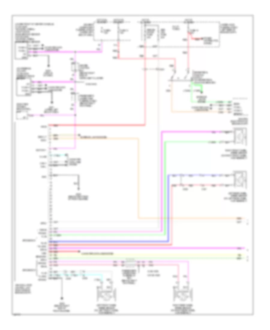
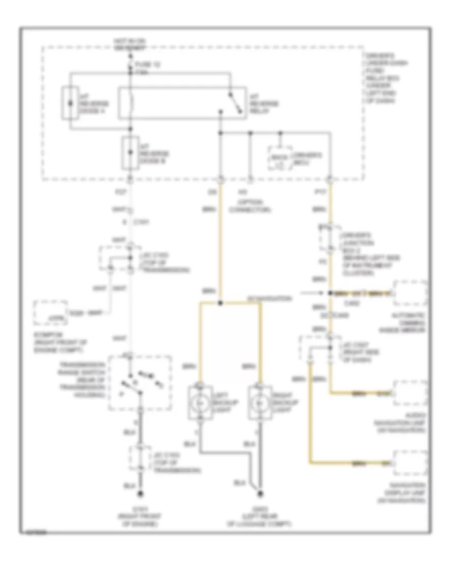
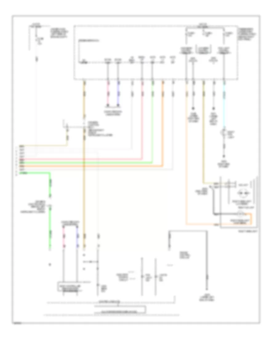
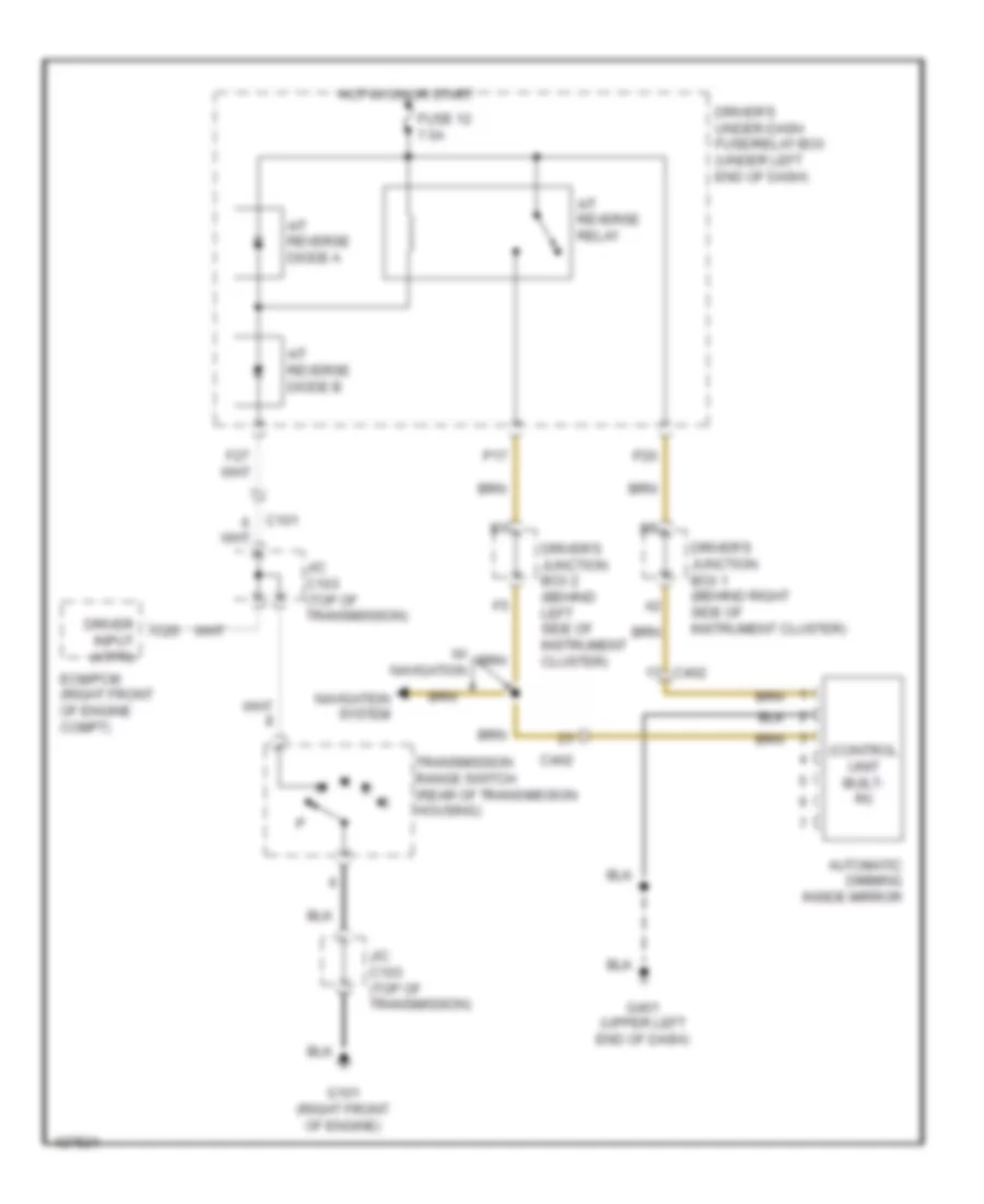
Backup Lamps Wiring Diagram, A/T for Acura TL 2014
List of elements for Backup Lamps Wiring Diagram, A/T for Acura TL 2014:
- (option connector)
- A/t reverse diode a
- A/t reverse diode b
- A/t reverse relay
- Atpr
- Audio/ navigation unit (w/ navigation)
- Automatic dimming inside mirror
- Back lt-
- C101
- C25
- C402
- C406
- Driver's junction box 2 (behind left side of instrument cluster)
- Driver's micu
- Driver's under-dash fuse/ relay box (under left end of dash)
- Ecm/pcm (right front of engine compt)
- F27
- Fuse 12 7.5a
- G10
- G101 (right front of engine)
- G603 (left rear of luggage compt)
- Hot in on or start
- J/c c103 (top of transmission)
- J/c c507 (right side of dash)
- Left backup light
- N d
- Navigation display unit (w/ navigation)
- P17
- Right backup light
- Transmission range switch (rear of transmission housing)
- W/ navigation
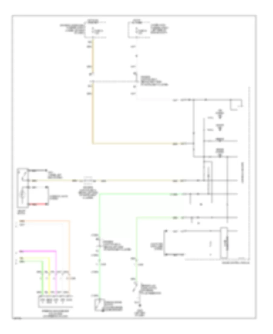
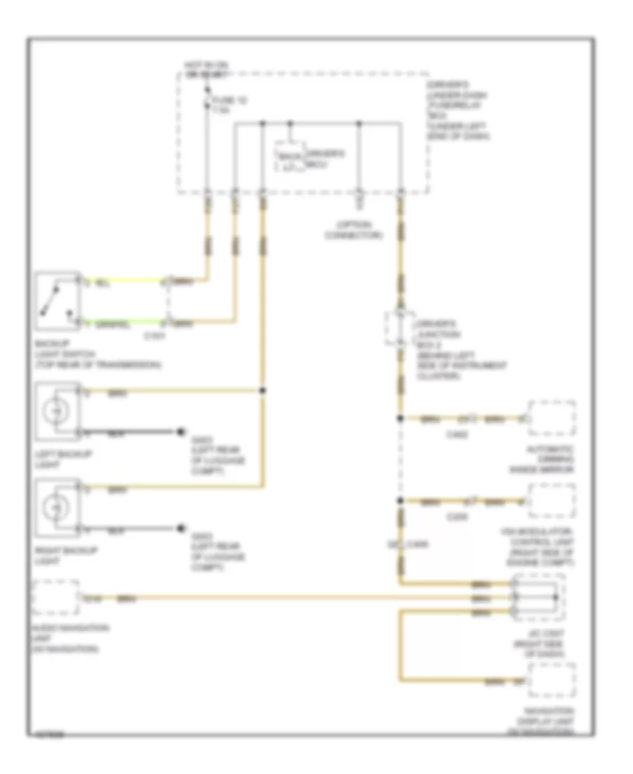
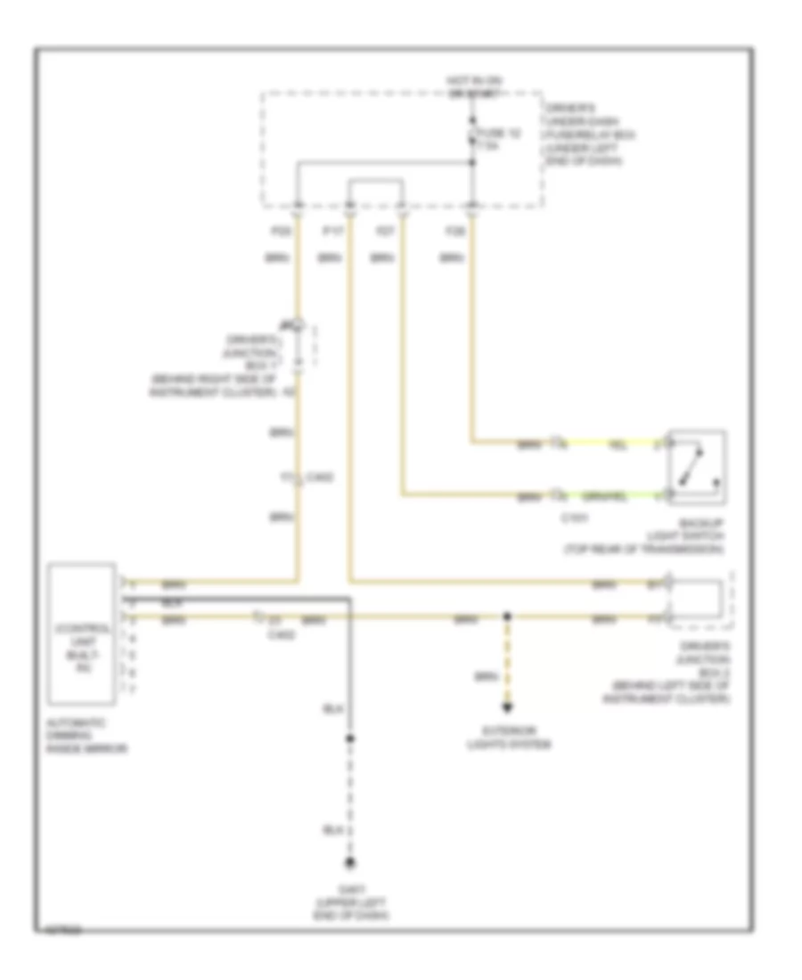
Backup Lamps Wiring Diagram, M/T for Acura TL 2014
List of elements for Backup Lamps Wiring Diagram, M/T for Acura TL 2014:
- (option connector)
- Audio navigation unit (w/ navigation)
- Automatic dimming inside mirror
- Back lt-
- Backup light switch (top rear of transmission)
- C101
- C206
- C402
- C406
- Driver's junction box 2 (behind left side of instrument cluster)
- Driver's micu
- Driver's under-dash fuse/relay box (under left end of dash)
- F27
- F28
- Fuse 12 7.5a
- G10
- G603 (left rear of luggage compt)
- Hot in on or start
- J/c c507 (right side of dash)
- Left backup light
- Navigation display unit (w/ navigation)
- P17
- Right backup light
- Vsa modulator- control unit (right side of engine compt)
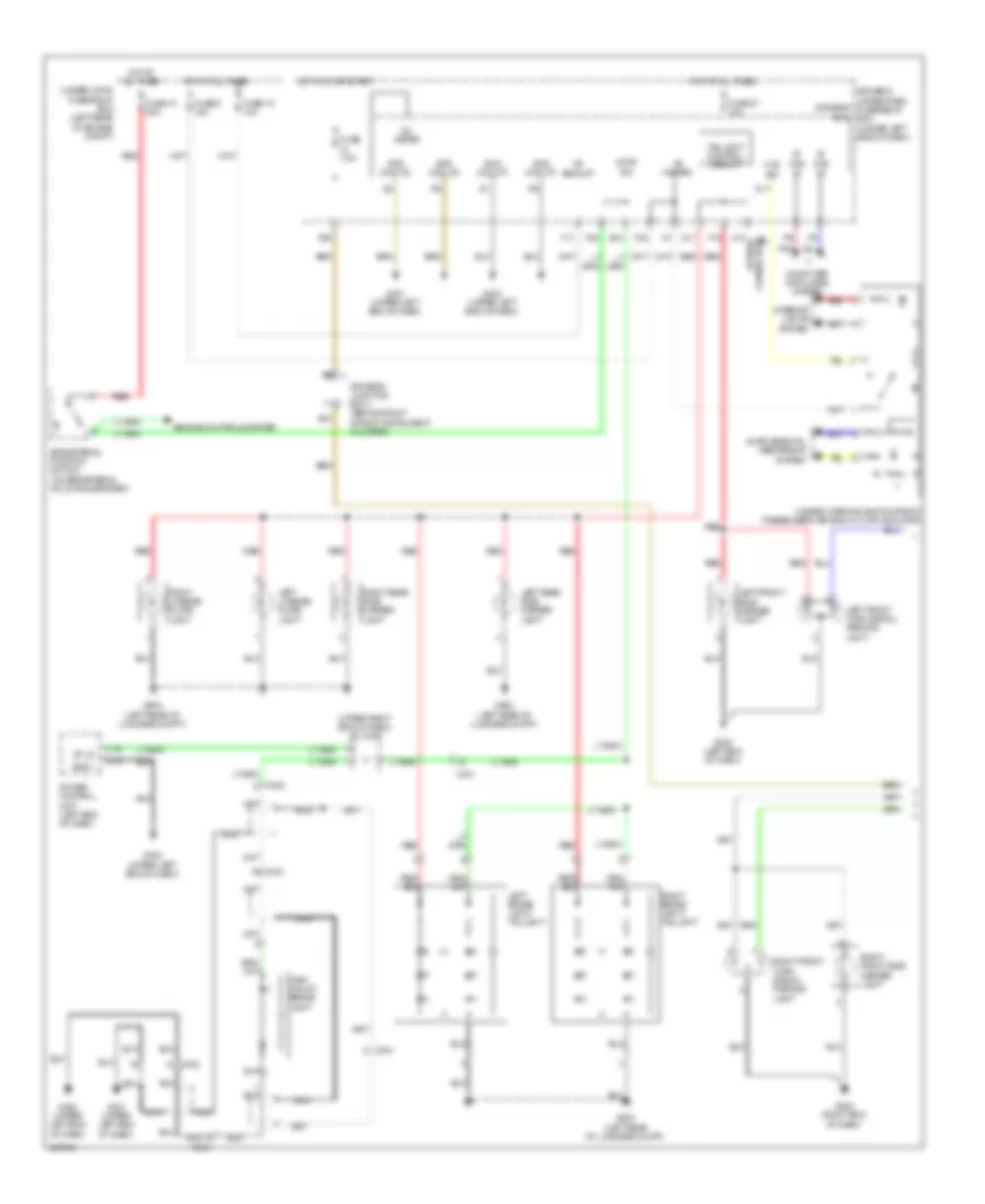
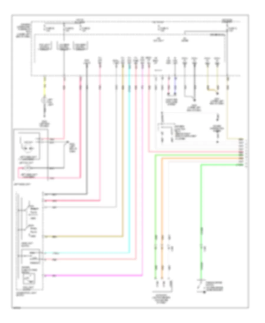
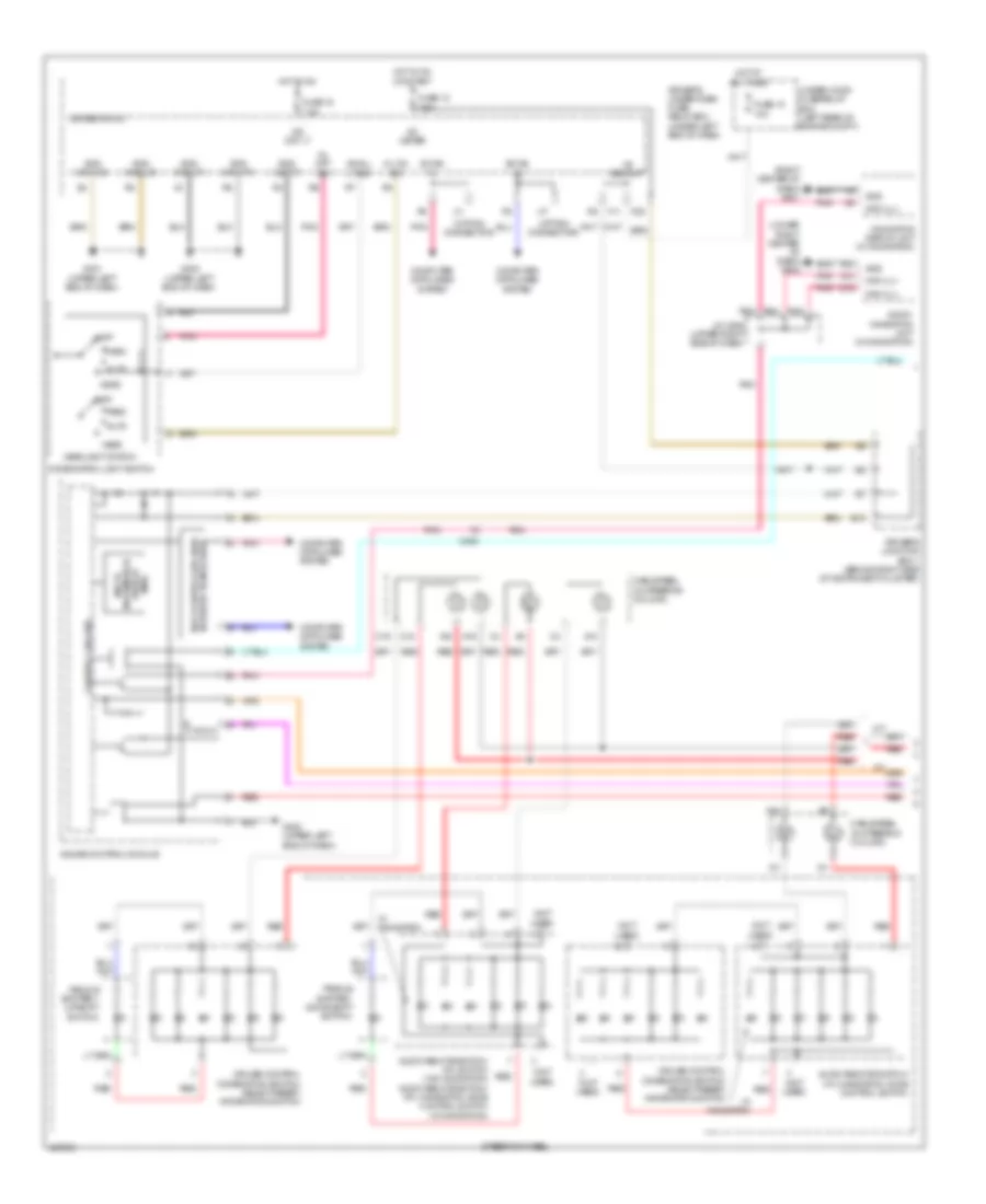
Exterior Lamps Wiring Diagram (1 of 2) for Acura TL 2014
List of elements for Exterior Lamps Wiring Diagram (1 of 2) for Acura TL 2014:
- (upper right end of dash) j/c c409
- +b backup
- +b hazard
- B- can hi
- B- can lo
- Brake pedal position switch (on brake pedal mounting bracket)
- C18
- C19
- C401
- C402
- C451
- Computer data lines system
- D11
- Driver's junction box 1 (behind right side of instrument cluster)
- Driver's micu
- Driver's under-dash fuse/relay box (under left end of dash)
- E10
- E12
- Engine controls system
- F10
- F11
- F20
- F32
- Fuse 10 20a
- Fuse 15 10a
- Fuse 27 10a
- Fuse 7.5a
- Fuse 9 15a
- G203 (right end of dash)
- G302 (left end of dash)
- G401 (upper left end of dash)
- G402 (upper left end of dash)
- G603 (left rear of luggage compt)
- Gnd (micu-p)
- Gnd (micu-s)
- Gnd1
- H10 (option connector)
- Haz sw
- Hazard warning switch/front passenger's air bag cut-off indicator
- High mount brake light
- Hot at all times
- Hot in on or start
- Ig1 meter
- Interior lights system
- Left brake light/ taillight
- Left front side marker light
- Left front turn signal/ parking light
- Left license plate light
- Left rear side marker light
- Nca
- P20
- Pnk
- Power control unit (left end of dash)
- Q17
- Red
- Right brake light/ taillight
- Right front side marker light
- Right front turn signal/ parking light
- Right license plate light
- Right rear side marker light
- St ls
- Stop sw
- Taillight control circuit
- Under-hood fuse/relay box (left rear of engine compt)
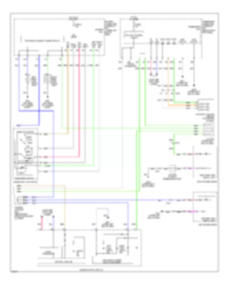
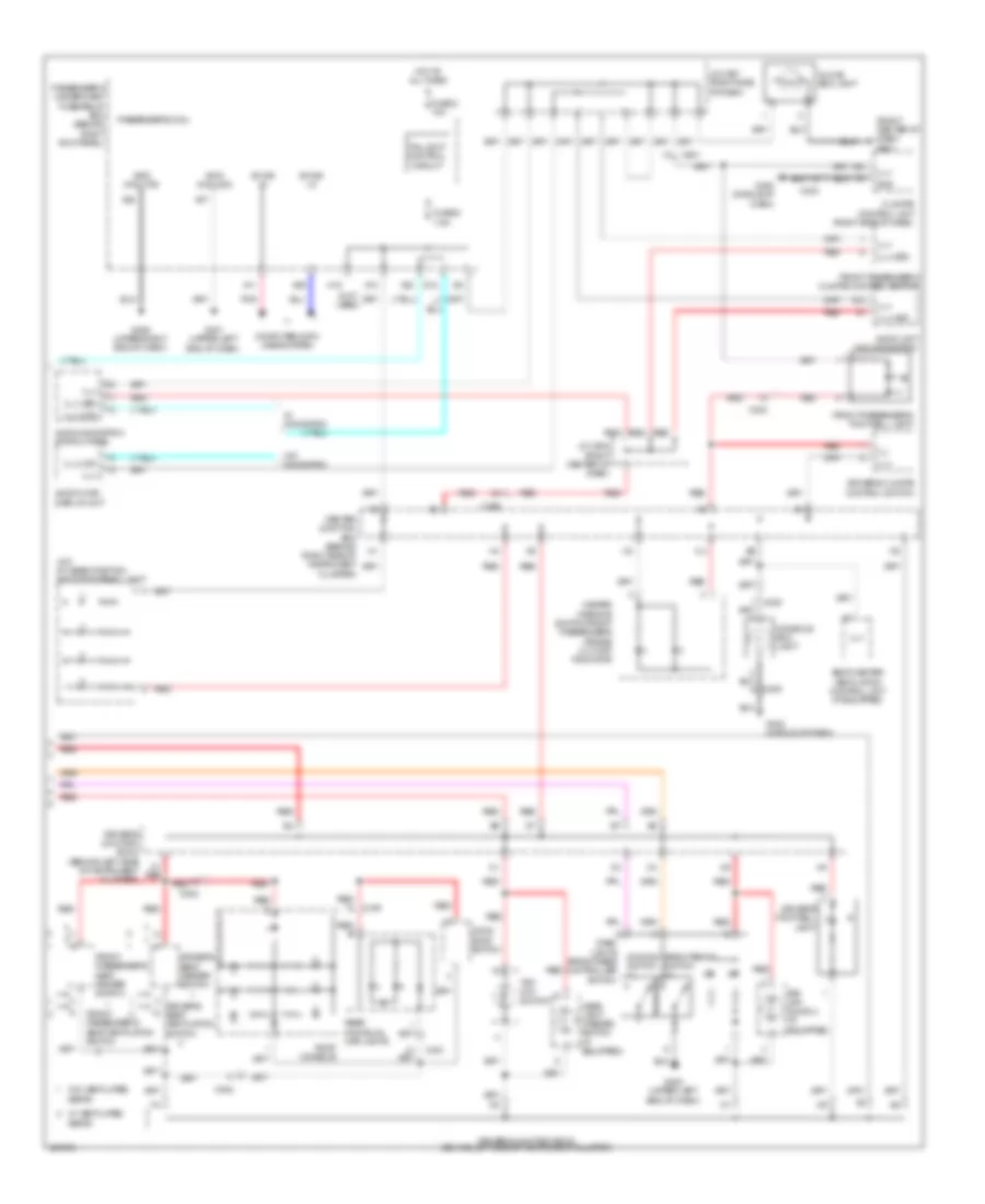
Exterior Lamps Wiring Diagram (2 of 2) for Acura TL 2014
List of elements for Exterior Lamps Wiring Diagram (2 of 2) for Acura TL 2014:
- A11
- A29
- A36
- A37
- Auto
- Auto lt sig
- Auto lt sio
- Auto lt sip
- Automatic lighting sensor (top center of dash)
- B- can hi
- B- can lo
- B-can transceiver
- C406
- C751
- C761
- Combination light switch
- Computer data lines system
- Control circuits
- D13
- D20
- Driver's junction box 1 (behind right side of instrument cluster)
- Driver's micu
- Driver's under-dash fuse/relay box (under left end of dash)
- E11
- E12
- Fuse 12 7.5a
- Fuse 2 10a
- G10
- G401 (upper left end of dash)
- G405 (upper right end of dash)
- G603 (left rear of luggage compt)
- Gauge control module
- Gnd (light)
- Gnd (micu-p)
- Gnd (micu-s)
- H/l off sw
- H/l on sw
- H36 (option connector)
- Head
- Headlight switch
- Hot at all times
- Hot in on or start
- Ig1 meter
- J/c c409 (upper right end of dash)
- J/c c762 (in front passenger's door)
- Left
- Left power mirror
- Left rear turn signal light
- Left side turn signal light
- Left turn signal ind
- Left turn sw
- Lights on ind
- Off
- P14
- Park
- Passenger's under-dash fuse/relay passenger's box micu (behind right kick panel)
- Pnk
- R13
- R14
- Right
- Right power mirror
- Right rear turn signal light
- Right side turn signal light
- Right turn signal ind
- Right turn sw
- Small lt sw
- Taillight control circuit
- Turn signal switch
- Turn signal/hazard flasher circuit
- Turn signal/hazard relay 2 (sounder)
GROUND DISTRIBUTION
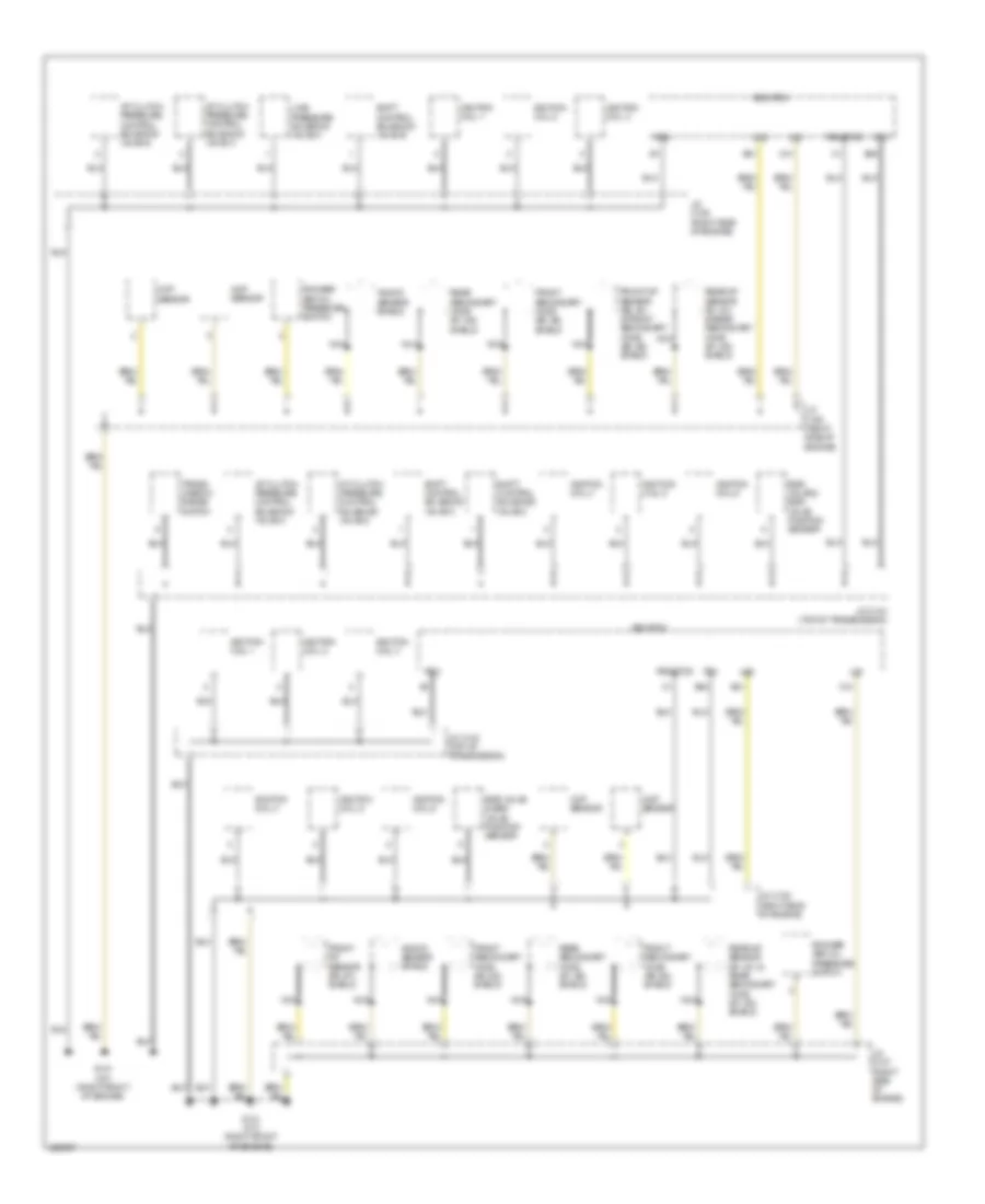
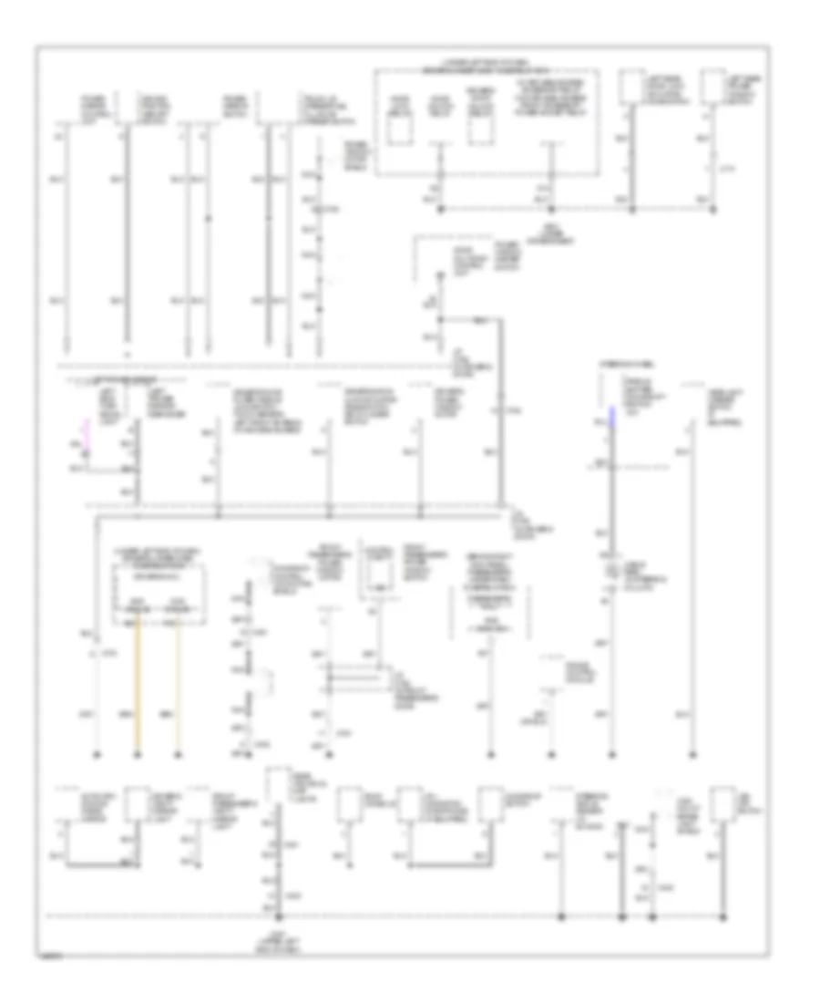
Ground Distribution Wiring Diagram (1 of 5) for Acura TL 2014
List of elements for Ground Distribution Wiring Diagram (1 of 5) for Acura TL 2014:
- A/t clutch pressure control solenoid valve a
- A/t clutch pressure control solenoid valve b
- A/t clutch pressure control solenoid valve c
- A/t clutch pressure control solenoid valve d
- B40
- B41
- C41
- Ckp sensor
- Cmp sensor
- Ecm/pcm
- Egr valve & egr valve position sensor
- Front a/f sensor (b2, s1) & front secondary ho2s (b2, s2) shield
- Front a/f sensor (b2, s1) shield
- Front secondary ho2s (b2, s2) shield
- G101 (a/t) (right front of engine)
- G101 (m/t) (right front of engine)
- Ignition coil 1
- Ignition coil 2
- Ignition coil 3
- Ignition coil 4
- Ignition coil 5
- Ignition coil 6
- J/c c103 (top of transmission)
- J/c c105 (right side of engine)
- J/c c106 (right side of engine)
- J/c c107 (right side of engine)
- Knock sensor shield
- Lg1
- Lg2
- Line pressure solenoid valve a
- Nca
- Pg1
- Pg2
- Pgmetcs
- Rear a/f sensor (b1, s1) & rear secondary ho2s (b1, s2) shield
- Rear secondary ho2s (b1, s2) shield
- Rocker arm oil pressure switch
- Shift control solenoid valve a
- Shift control solenoid valve b
- Shift control solenoid valve c
- Trans- mission range switch
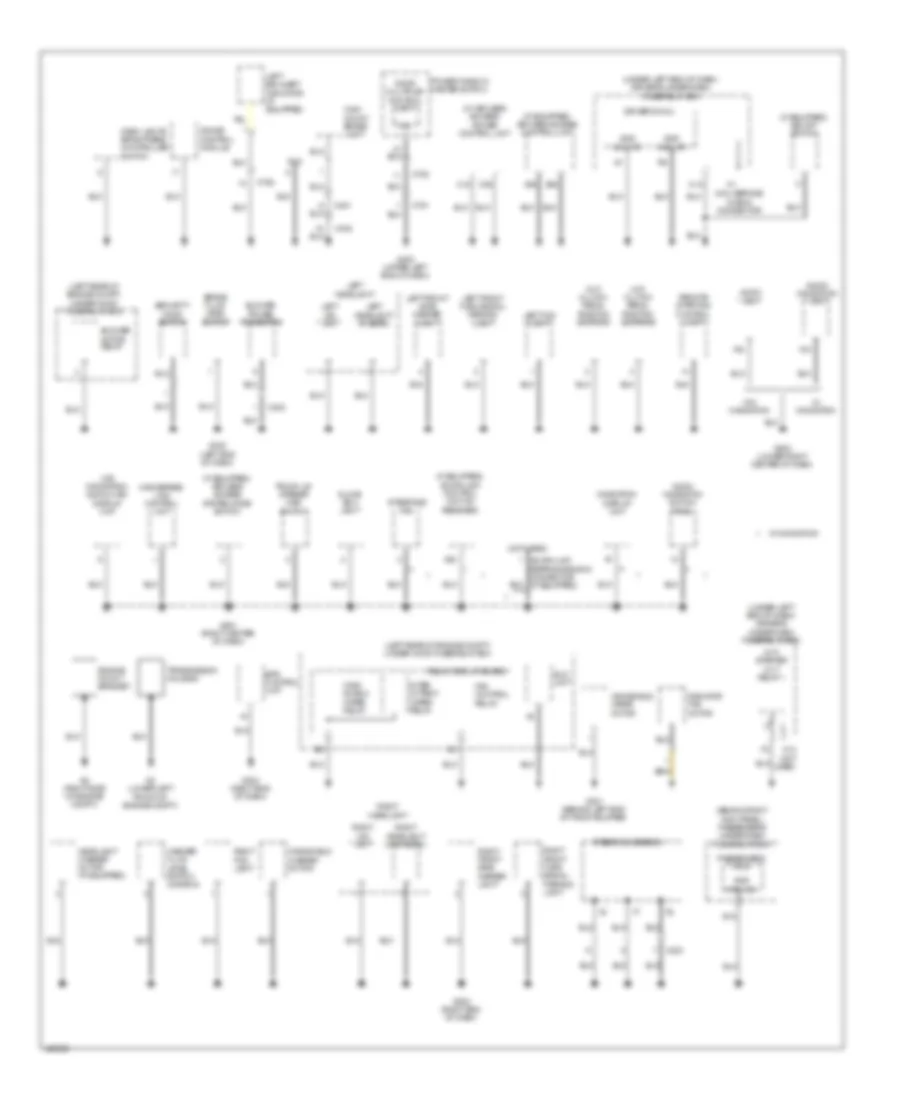
Ground Distribution Wiring Diagram (2 of 5) for Acura TL 2014
List of elements for Ground Distribution Wiring Diagram (2 of 5) for Acura TL 2014:
- (behind right kick panel) passenger's under-dash fuse/relay box
- (if equipped) acura link control unit (xm receiver)
- (if equipped) bsi off switch
- (if equipped) keyless access control unit
- (if equipped) keyless access system mode switch
- (left rear of engine compt) under-hood fuse/relay box
- (m/t) clutch pedal position switch a
- (m/t) clutch pedal position switch b
- (m/t) starter cut relay 1
- (micu-s)
- (not used)
- (under left end of dash) driver's under-dash fuse/relay box
- (w/ keyless access) power control unit
- (w/0 navigation) audio-hvac display unit
- A12
- A28
- A36
- Acura link reprogramming connector (if equipped)
- Audio navigation switch panel
- Audio unit
- Audio- navigation unit
- B32
- Blower motor relay
- Blower power transistor
- Brake fluid level switch
- C18
- C203
- C302
- C36
- C402
- C451
- C751
- C752
- C753
- Dash lights brightness controller switch
- Dlc
- Door multiplex control unit
- Driver's micu
- E15
- Eld unit
- Engine mount bracket
- Eps control unit
- Fan control relay
- G2 (right side of engine compt)
- G203 (right end of dash)
- G204 (right end of dash)
- G3 (lower left front of engine compt)
- G301 (behind left end of front bumper)
- G302 (left end of dash)
- G402 (upper left end of dash)
- G501 (right center of dash)
- G502 (lower right center of dash)
- Gauge control module
- Glove box light
- Gnd
- Gnd (micu-p)
- Handsfree- link control unit
- Headlight washer motor (if equipped)
- High mount brake light
- Inter mittent wiper relay
- Interface dial
- Left bsi alert indicator (if equipped)
- Left fog light
- Left front side marker light
- Left front turn signal/ parking light
- Left headlight
- Left headlight (hi beam)
- Left hid unit
- Micu service check connector
- N12
- N13 (not used)
- Navigation display unit
- Passenger's micu
- Power window master switch
- Radiator fan motor
- Relay circuit board
- Remote starting control unit
- Right fog light
- Right front side marker light
- Right front turn signal/ parking light
- Right headlight
- Right headlight (high beam)
- Right hid unit
- Security hood switch
- Steering gearbox
- Transmission housing
- Trunk lid opener main switch
- W/ navigation
- W/o navigation
- Washer fluid level switch (canada)
- Wind shield wiper relay
- Windshield washer motor
- Windshield wiper motor
Ground Distribution Wiring Diagram (3 of 5) for Acura TL 2014
List of elements for Ground Distribution Wiring Diagram (3 of 5) for Acura TL 2014:
- (a/t) paddle shifter+ (upshift switch)
- (a/t) park pin switch
- (behind right kick panel) passenger's under-dash fuse/relay box
- (w/ keyless access) electric steering lock control unit
- (w/ keyless access) engine start/stop switch
- (w/ keyless access) front passenger's door outer handle lock switch/ touch sensor/ left front antenna
- (w/ keyless access) remote slot
- (w/ keyless access) remote slot control unit
- (w/o headlight washer) relay block 1 (w/ headlight washer) relay block 2
- (w/o keyless access) (ignition key switch/key light/ key interlock solenoid) steering lock
- +b cut relay (m/t)
- A/t shift lock solenoid/park pin switch
- A28
- A29
- A36
- Battery
- Battery sensor
- C12
- C402
- C403
- C405
- C406
- C451
- C761
- Cable reel (in steering column)
- Climate control unit
- Console accessory power socket
- Console accessory power socket relay
- Console box light
- Control unit
- Cruise control combination switch/ select/reset/ information switch
- Driver's climate control switch
- Driver's seat heater switch
- Front accessory power socket
- Front accessory power socket relay
- Front passenger's climate control switch
- Front passenger's door lock actuator/ knob switch
- Front passenger's power window switch
- Front passenger's seat heater switch
- Fuel tank unit
- G1 (left front of engine compt)
- G202 (behind right end of front bumper)
- G403 (middle of dash)
- G404 (under left side of center console)
- G405 (upper right end of dash)
- G602 (under left rear seat)
- G653 (right rear of luggage compt)
- Gnd (micu-p)2
- J/c c762 (in front passenger's door)
- Moonroof control unit/ motor
- Nca
- Passenger's micu
- Relay block 1
- Relay block 2
- Right bsi alert indicator (if equipped)
- Right power mirror
- Right power mirror defogger
- Right side turn signal light
- Seat ventilation control unit
- Seat ventilation relay
- Srs unit
- Steering wheel
- Stereo amplifier
- Tpms control unit
- Vsa modulator control unit
- W/ ventilated seats
- W/o ventilated seats
- Yaw rate-lateral acceleration sensor (w/o sh-awd) yaw rate-lateral/ longitudinal acceleration sensor (w/ sh-awd)
Ground Distribution Wiring Diagram (4 of 5) for Acura TL 2014
List of elements for Ground Distribution Wiring Diagram (4 of 5) for Acura TL 2014:
- (behind right kick panel) passenger's under-dash fuse/relay box
- (not used)
- (w/ bsi system) bsi control unit
- (w/ bsi system) left bsi radar unit
- (w/ sh-awd)
- (w/o sh-awd)
- A18
- Backup sensor beeper
- Backup sensor control unit
- C652
- C701
- C702
- C781
- D12
- Door lock relay
- Door unlock relay
- Driver's lumbar support switch
- Driver's seat back blower motor
- Driver's seat back heater
- Driver's seat belt buckle switch
- Driver's seat cushion blower motor
- Driver's seat cushion heater
- Driver's seat heater
- Driver's seat heater relay (high)
- Driver's seat heater relay (low)
- Driver's seat heater relay box
- Driver's seat position sensor
- Electrical compass unit (w/o navigation)
- Front passenger's power seat adjustment switch
- Front passenger's seat back blower motor
- Front passenger's seat belt buckle switch
- Front passenger's seat cushion blower motor
- Front passenger's seat cushion heater
- Front passenger's seat heater
- Front passenger's seat heater relay (high)
- Front passenger's seat heater relay (low)
- Front passenger's seat heater relay box
- Fuel fill door opener solenoid
- G603 (left rear of luggage compt)
- G651 (under front passenger's seat)
- G652 (w/ sh-awd) (base of right "c" pillar)
- G701 (under driver's seat)
- G702 (under front passenger's seat)
- G801 (right "c" pillar)
- Keyless buzzer
- Left backup light
- Left brake light/ taillight
- Left license plate light
- Left rear side marker light
- Left rear turn signal light
- Nca
- Ods unit
- Power seat control unit
- Rear differential (w/ sh-awd)
- Rear window defogger
- Rear window defogger noise condenser
- Rearview camera connector
- Relay block 3
- Right backup light
- Right brake light/ taillight
- Right bsi radar unit
- Right license plate light
- Right rear door lock actuator/ knob switch
- Right rear power window switch
- Right rear side marker light
- Right rear turn signal light
- Sh-awd control unit
- Sh-awd relay
- Trunk lid latch switch/ trunk lid release actuator
- Trunk lid spoiler switch (w/ keyless access)
- W/ navigation
- W/ ventilated seats
- W/o ventilated seats
Ground Distribution Wiring Diagram (5 of 5) for Acura TL 2014
List of elements for Ground Distribution Wiring Diagram (5 of 5) for Acura TL 2014:
- (behind right kick panel) passenger's under-dash fuse/relay box
- (micu-s)2
- (under left end of dash) driver's under-dash fuse/relay box
- (w/ keyless access) accessory relay (w/o keyless access) front accessory power socket relay
- A37
- Automatic dimming inside mirror
- C402
- C451
- C751
- C753
- C754
- C761
- C771
- Cable reel (in steering column)
- Control unit
- D14
- Dlc
- Door lock relay
- Door multiplex control unit
- Door unlock relay
- Driver's door lock actuator/ knob switch/ key cylinder switch
- Driver's door outer handle lock switch/ touch sensor/ left front antenna (w/ keyless access)
- Driver's door unlock relay
- Driver's micu
- Driver's power window motor
- Driver's vanity mirror light
- Driving position memory switch
- Front passenger's power window motor
- Front passenger's power window switch
- Front passenger's vanity mirror light
- G401 (upper left end of dash)
- G601 (under driver's seat)
- Gauge control module
- Gnd
- Gnd (micu-s)
- Headlight washer switch (if equipped)
- Hfl- navigation microphone (if equipped)
- High mount brake light shield
- J/c c755 (in driver's door)
- J/c c756 (in driver's door)
- J/c c762 (in front passenger's door)
- Left power mirror
- Left power mirror defogger
- Left rear door lock actuator/ knob switch
- Left rear power window switch
- Left side turn signal light
- Moonroof control unit/motor shield
- Moonroof switch
- Nca
- Paddle shifter- (downshift switch) (a/t)
- Passenger's micu
- Power mirror control unit
- Power mirror switch
- Power window master switch
- Power window motor shield
- Rear individual map lights
- Roof console
- Steering angle sensor (w/ sh-awd)
- Steering wheel
- Trunk lid opener/fuel fill door opener switch
- Vsa off switch
HEADLIGHTS
Headlights Wiring Diagram (1 of 2) for Acura TL 2014
List of elements for Headlights Wiring Diagram (1 of 2) for Acura TL 2014:
- (light)
- (micu- p) gnd q1
- (micu- p) gnd r5
- (micu- s)
- +b back up
- Auto
- Automatic lighting sensor (top center of dash)
- B can high
- B can low
- Back- up h/l
- C405
- C406
- Combination light switch
- Computer data lines system
- Dimmer/ flash-to-pass switch
- Driver's junction box 1 (behind right side of instrument cluster)
- Driver's micu
- Driver's under-dash fuse/relay box (under left end of dash)
- F11
- F13
- F21
- Fog light control circuit
- Fog light switch
- Fr fog sw
- Fuse 12 7.5a
- Fuse 15 7.5a
- Fuse 26 10a
- Fuse 28 10a
- Fuse 30 15a
- G12
- G302 (left end of dash)
- G401 (upper left end of dash)
- G402 (upper left end of dash)
- Gnd
- Gnd q2
- Gnd r2
- H/l
- H/l dim sw
- H/l off sw
- H/l on sw
- Head
- Headlight switch
- Hid unit
- High
- High beam control circuit
- Hot at all times
- Hot in on
- Hot in on or start
- Ig1 meter
- Ig2 day light
- Left fog light
- Left headlight
- Left headlight (high beam)
- Left headlight (low beam)
- Left hid unit
- Low
- Low beam control circuit
- Lt sig
- Lt sio
- Lt sip
- Off
- P20
- Park
- Parking brake switch (on park brake lever bracket)
- Pass sw
- Passing
- Pnk
- Power distribution system
- R10
- R21
- R22
- Red
- Small lt sw
Headlights Wiring Diagram (2 of 2) for Acura TL 2014
List of elements for Headlights Wiring Diagram (2 of 2) for Acura TL 2014:
- +b back up
- A11
- A14
- A17
- A29
- A35
- A36
- A37
- Auto lt sig
- Auto lt sio
- Auto lt sip
- B-can
- Back- up h/l
- Body controller area network transceiver
- Computer data lines system
- Control circuits
- D20
- Driver's junction box 1 (behind right side of instrument cluster)
- Driver's junction box 2 (behind left side of instrument cluster)
- E10
- E13
- Fog light control circuit
- Fog light ind
- Fuse 1 10a
- Fuse 10a
- Fuse 3 10a
- Fuse 4 15a
- G203 (right end of dash)
- G401 (upper left end of dash)
- G402 (upper left end of dash)
- G405 (upper right end of dash)
- Gauge control module
- Gnd (micu-p)
- Gnd (micu-s)
- Hid unit
- High
- High beam control circuit
- High beam ind
- Hot at all times
- Ig1 meter
- Indicator dimming circuit
- Lights on ind
- Low
- Low beam control circuit
- Multi-information display (mid)
- Passenger's micu
- Passenger's under-dash fuse/relay box (behind right kick panel)
- Pnk
- Red
- Right fog light
- Right headlight
- Right headlight (high beam)
- Right headlight (low beam)
- Right hid unit
- Under-hood fuse/relay box (left rear of engine compt)
HORN
Horn Wiring Diagram for Acura TL 2014
List of elements for Horn Wiring Diagram for Acura TL 2014:
- (not used)
- B11
- C11
- Cable reel (in steering column)
- Cruise control combination/ select/reset/ information switch
- Driver's micu
- Driver's under-dash fuse/relay box (under left end of dash)
- F23
- Fuse 20a
- High horn (behind left side of front bumper)
- Horn relay
- Horn rly ct
- Horn sw
- Horn switch
- Hot at all times
- Low horn (behind right side of front bumper)
- Q12
- Red
- Relay circuit board
- Steering wheel
- Under-hood fuse/relay box (left rear of engine compt)
INSTRUMENT CLUSTER
Instrument Cluster Wiring Diagram (1 of 2) for Acura TL 2014
List of elements for Instrument Cluster Wiring Diagram (1 of 2) for Acura TL 2014:
- (red)
- (under left side of dash) g402
- (w/o keyless access) immobilizer system ind
- (white)
- Abs ind
- Anti-lock brakes system
- At backlight
- Beeper
- Body controller area network transceiver
- Brake system ind
- Bsi ind (if equipped)
- Charging system ind
- Computer data lines system
- Control circuits
- Cruise control ind
- Cruise control main switch ind
- Cruise control system
- Door/trunk open lid ind
- Engine coolant temperature gauge
- Eps ind
- Exterior lights system
- Fog light ind
- Fuel gauge
- G401 (upper left end of dash)
- Gauge control module
- High beam ind
- Illumination (white)
- Illumination dial plates
- Illumination pointers
- Indicator dimming circuit
- Interior lights system
- Keyless access ind (if equipped)
- Led light
- Left turn signal ind
- Lights on ind
- Lin transceiver
- Low fuel ind
- Low oil pressure ind
- Low tire pressure/tpms ind
- Matic illumination (white) (a/t)
- Message ind
- Mid illumination
- Mid illumination (amber)
- Mil ind
- Multi-information display (mid) unit
- Network transceiver fast controller area
- Pnk
- Red
- Right turn signal ind
- Seat belt reminder ind
- Security ind
- Sh-awd ind (if equipped)
- Shift indicator driver circuit
- Side air bag cut-off ind
- Speaker control
- Speedometer
- Srs ind
- Tachometer
- Turn signal/ hazard relay 2 (sounder)
- Vsa off ind
- Vsa system ind
- Wiper/washer system
Instrument Cluster Wiring Diagram (2 of 2) for Acura TL 2014
List of elements for Instrument Cluster Wiring Diagram (2 of 2) for Acura TL 2014:
- (under left end of dash) (w/ keyless access) keyless access control unit
- A11
- A13
- A14
- A29
- A48
- A49
- B-can hi
- B-can lo
- B24
- B26
- Brake fluid level switch (on brake fluid reservoir)
- C13
- C14
- C22
- C306
- C401
- C404
- C405
- C45
- C701
- Cable reel (in steering column)
- Computer data lines system
- Cruise control combination/ select/reset/ information switch
- D12
- Driver's door switch (in driver's "b" pillar)
- Driver's junction box 1 (behind right side of instrument cluster)
- Driver's junction box 2 (behind left side of instrument cluster)
- Driver's micu
- Driver's under-dash fuse/relay box (under left end of dash)
- E10
- Ecm/pcm (right front of engine compt)
- F-canh
- F-canl
- Fr door sw l
- Fr door sw r
- Front passenger's door switch (in front passenger's "b" pillar)
- Fuel gauge sending unit
- Fuel tank unit
- Fuse 12 7.5a
- Fuse 15 10a
- G14
- G15
- G302 (left end of dash)
- G603 (left rear of luggage compartment)
- H25
- Hot at all times
- Hot in on or start
- Interior lights system
- Keyless access junction box (under left end of dash)
- Left rear door switch (in left rear "c" pillar)
- Next switch
- Oil pressure switch
- Opsw
- P20
- Parking brake switch (on park brake lever bracket)
- Passenger's micu
- Passenger's under-dash fuse/relay box passenger's micu (behind right kick panel)
- Pnk
- Power control unit (w/ keyless access) (left end of dash)
- Power seat control unit (m/t) (under driver's seat)
- Red
- Remote slot control unit (w/ keyless access) (right end of dash)
- Right rear door switch (in right rear "c" pillar)
- Rr door sw l
- Rr door sw r
- Secondary fuel gauge sending unit (top right side of fuel tank)
- Select/ reset switch
- Steering wheel
- Trunk lid latch switch
- Trunk lid latch switch/ trunk lid release actuator (bottom middle rear of of luggage compartment lid)
- Trunk sw
- Under-hood fuse/relay box (left rear of engine compt)
- W/ sh-awd
- W/o sh-awd
INTERIOR LIGHTS
Courtesy Lamps Wiring Diagram for Acura TL 2014
List of elements for Courtesy Lamps Wiring Diagram for Acura TL 2014:
- (option connector)
- (upper left end of dash) g401
- +b backup
- 5v regulator
- A10
- A11
- A29
- A33
- B-can hi
- B-can lo
- C402
- C451
- C601
- C751
- C753
- C761
- Cargo lt
- Center junction box (behind right side of instrument cluster)
- Computer data lines system
- Control circuit
- D12
- Door mode on/off ind
- Driver's door courtesy light
- Driver's door switch (in driver's "b" pillar)
- Driver's junction box 1 (behind right side of instrument cluster)
- Driver's micu
- Driver's under-dash fuse/relay box (under left end of dash)
- Driver's vanity mirror light
- F11
- F29
- Fr courtesy lt
- Fr courtesy r
- Fr door sw l
- Fr door sw r
- Front individual map lights
- Front passenger's door courtesy light
- Front passenger's door switch (in front passenger's "b" pillar)
- Front passenger's vanity mirror light
- Fuse 12 10a
- Fuse 15 10a
- Fuse 16 7.5a
- G14
- G15
- G401 (upper left end of dash)
- G603 (left rear of luggage compt)
- H25
- Hot at all times
- Ig key lt-
- Ignition key light
- Interior light control switch (door)
- Interior light control switch off
- Interior light control switch on
- Intr lt-
- J/c c756 (in driver's door)
- Left map light
- Left map light switch
- Left map lights
- Left map lights (x2)
- Left rear door switch (in left "c" pillar)
- Off
- P19
- Passenger's micu
- Passenger's under-dash fuse/relay box (behind right kick panel)
- Pnk
- Power distribution system
- Q11
- Q4 map lt off
- Rear individual map lights
- Red
- Remote slot
- Right map light switch
- Right map lights
- Right map lights (x2)
- Right rear door switch (in right "c" pillar)
- Roof console
- Rr door sw l
- Rr door sw r
- Steering lock (ignition key switch/ key light/ key interlock solenoid)
- Switch
- Trunk lid latch switch
- Trunk lid latch switch/trunk lid release actuator (bottom middle rear of luggage compt lid)
- Trunk light
- Trunk sw
- Under-hood fuse/relay box (left rear of engine compt)
- Visor open
- W/ keyless access
- W/ navigation
- W/ sh-awd
- W/o keyless access
- W/o navigation
- W/o sh-awd
Entry Light Timer Wiring Diagram (1 of 2) for Acura TL 2014
List of elements for Entry Light Timer Wiring Diagram (1 of 2) for Acura TL 2014:
- (left end of dash) power control unit
- (option connector)
- (right end of dash) remote slot control unit
- +b backup
- A10
- Antenna
- B-can hi
- B-can lo
- B15
- C14
- C402
- C751
- C753
- Computer data lines system
- D12
- Driver's door switch (in driver's "b" pillar)
- Driver's junction box 1 (behind right side of instrument cluster)
- Driver's micu
- Driver's under-dash fuse/relay box (under left end of dash)
- F11
- F29
- Fr door sw l
- Fuse 12 10a
- Fuse 12 7.5a
- G401 (upper left end of dash)
- G402 (upper left end of dash)
- G403 (middle of dash)
- Hot at all times
- Hot in on or start
- Ig key lt-
- Ig q18
- Ig1
- Ignition key light
- Ignition key switch
- Immobilizer keyless control unit (w/o keyless access) (on steering column)
- Intr lt-
- Key lt sw
- Keyless access control unit (w/ keyless access) (under left end of dash)
- Left rear door switch (in left "c" pillar)
- Map lt off
- Meter
- P19
- P20
- Passenger's under-dash fuse/relay box (behind right kick panel)
- Pcu key
- Pnk
- Power distribution system
- Q1 gnd (micu-p)
- Q11
- Q2 gnd (micu-s)
- R2 gnd (micu-s)
- R5 gnd (micu-p)
- Red
- Remote
- Rf data
- Rf gnd
- Rf unit (under center console)
- Rr door sw l
- Steering lock (ignition key switch/ key light/key interlock solenoid)
- Transmitter
- Vbu
- Vout rf
- W/ keyless access
- W/o keyless access
Entry Light Timer Wiring Diagram (2 of 2) for Acura TL 2014
List of elements for Entry Light Timer Wiring Diagram (2 of 2) for Acura TL 2014:
- (not used)
- (upper left end of dash) g402
- +b backup
- 5v regulator
- A11
- A14
- A29
- A35
- A36
- A37
- B-can h
- B-can hi
- B-can l
- B-can lo
- C402
- C451
- C751
- C753
- C754
- Center junction box (behind right side of instrument cluster)
- Computer data lines system
- Control circuit
- Door lock knob
- Door mode on/off ind
- Door multiplex control unit
- Driver's door key cylinder switch
- Driver's door lock actuator/ knob switch/ key cylinder switch
- Driver's junction box 1 (behind right side of instrument cluster)
- E15
- E16
- Fr door sw r
- Front individual map lights
- Front passenger's door switch (in front passenger's "b" pillar)
- Fuse 15 10a
- Fuse 16 7.5a
- G14
- G15
- G203 (right end of dash)
- G401 (upper left end of dash)
- G405 (upper right end of dash)
- Gnd (micu-p)
- Gnd (micu-p)2
- Gnd (micu-s)
- Gnd (micu-s)2
- H25
- Hot at all times
- Ig1
- Interior light control switch (door)
- Interior light control switch off
- Interior light control switch on
- J/c c755 (in driver's door)
- J/c c756 (in driver's door)
- Key
- Left map light switch
- Left map lights
- Left map lights (x2)
- Lock
- Meter
- Passenger's micu
- Passenger's under-dash fuse/relay box (behind right kick panel)
- Pnk
- Power distribution system
- Power window master switch
- Rear individual map lights
- Right map light switch
- Right map lights
- Right map lights (x2)
- Right rear door switch (in right "c" pillar)
- Roof console
- Rr door sw r
- Under-hood fuse/relay box (left rear of engine compt)
- Unlock
- Vbu
- W/ sh-awd
- W/o sh-awd
Instrument Illumination Wiring Diagram (1 of 2) for Acura TL 2014
List of elements for Instrument Illumination Wiring Diagram (1 of 2) for Acura TL 2014:
- (lower right center of dash) g502
- (mid) display information multi-
- (not used)
- (option connector)
- (right center of dash) g501
- +b backup
- A/t
- A10
- A12
- A13
- A18
- A19
- Audio remote switch/ hfl-navigation voice control switch
- Audio- navigation unit (w/ navigation)
- Auto
- B-can
- C18
- C19
- C406
- Cable reel (in steering column)
- Combination light switch
- Computer data lines system
- Control circuits
- Cruise control combination switch/ select/reset/ information switch
- D16
- Driver's junction box 1 (behind right side of instrument cluster)
- Driver's micu
- Driver's under-dash fuse/ relay box (under left end of dash)
- E10
- F11
- Fuse 12 7.5a
- Fuse 15 10a
- Fuse 15 7.5a
- G401 (upper left end of dash)
- G402 (upper left end of dash)
- Gauge control module
- Gnd
- Gnd (light)
- Gnd (micu-p)
- Gnd (micu-s)
- H/l off sw
- H/l on
- Head
- Headlight switch
- Hot at all times
- Hot in on
- Hot in on or start
- Ig1 meter
- Ig2 day lt
- J/c c506 (upper right side of dash)
- Lt sw
- M/t
- Navi ill+
- Navigation display unit (w/ navigation)
- Network transceiver body controller area
- Off
- P20
- Paddle shifter + (upshift switch)
- Paddle shifter - (downshift switch)
- Park
- Pnk
- Red
- Small
- Steering wheel
- Under-hood fuse/relay box (left rear of engine compt)
- W/ navigation
Instrument Illumination Wiring Diagram (2 of 2) for Acura TL 2014
List of elements for Instrument Illumination Wiring Diagram (2 of 2) for Acura TL 2014:
- (a/t) a/t gear position indicator panel light
- (not used)
- (right center of dash) g501
- A11
- A13
- A29
- A30
- A36
- A37
- Audio unit (w/o navigation)
- Audio-hvac display unit
- Audio-navigation switch panel
- B-can hi
- B-can lo
- Brightening switch (+)
- Bsi off switch (if equipped)
- C402
- C403
- C405
- C406
- C451
- C501
- Center junction box (behind right side of instrument cluster)
- Climate control unit (right side of dash)
- Computer data lines system
- Console box light
- D12
- Dash lights brightness controller
- Dimming switch (-)
- Driver's climate control switch
- Driver's footwell light
- Driver's junction box 2 (behind left side of instrument cluster)
- Driver's seat heater switch
- Driver's seat ventilation switch
- F7 red
- Front passenger's climate control switch
- Front passenger's footwell light
- Front passenger's seat heater switch
- Front passenger's seat ventilation switch
- Fuse 2 10a
- Fuse 6 7.5a
- G401 (upper left end of dash)
- G402 (upper left end of dash)
- G403 (middle of dash)
- G405 (upper right end of dash)
- Glove box light
- Gnd
- Gnd (micu-p)2
- Gnd (micu-s)2
- H18
- Hazard warning switch/front passenger's air bag cut-off indicator
- Head light washer switch (if equipped)
- Hot at all times
- Ill+
- Ill-
- Ill-(lcd)
- Ill-(led)
- J/c c504 (right center of dash)
- J/c c507 (right side of dash)
- Moon roof switch
- Passenger's micu
- Passenger's under-dash fuse/relay box (behind right kick panel)
- Pnk
- Rear individual map lights
- Red
- Roof console
- Seat center ventilation control unit (if equipped)
- Seats
- Switch
- Taillight control circuit
- Vsa off switch
- W/ navigation
- W/ ventilated seats
- W/o navigation
- W/o ventilated
MEMORY SYSTEMS
Driver"s Memory Seat Wiring Diagram (1 of 2) for Acura TL 2014
List of elements for Driver"s Memory Seat Wiring Diagram (1 of 2) for Acura TL 2014:
- (under driver's seat) g701
- A/t
- Atp-p
- B-can hi
- B-can lo
- C101
- C306
- C404
- C405
- C701
- C751
- C754
- Computer data lines system
- Driver's junction box 1 (behind right side of instrument cluster)
- Driver's junction box 2 (behind left side of instrument cluster)
- Driver's power seat front up-down motor/position sensor (under right rear of driver's seat)
- Driver's power seat rear up-down motor/position sensor (under right rear of driver's seat)
- Driver's power seat recline motor/position sensor (under right rear of driver's seat)
- Driver's power seat slide motor/position sensor (under right rear of driver's seat)
- Driver's under-dash fuse/relay box (under left end of dash)
- Fhdn
- Fhm +
- Fhm -
- Fhse
- Fhup
- Fuse 12 7.5a
- Fuse 15 10a
- Fuse 19 20a
- Fuse 21 20a
- G101 (right front of engine)
- G701 (under driver's seat)
- Gnd
- Hot at all times
- Hot in on or start
- Ig1
- J/c c103 (top of transmission)
- J/c c307 (left side of dash)
- M/t
- P11
- P12
- P20
- Parking brake switch (on park brake lever bracket)
- Pnk
- Power mirror control unit
- Power seat control unit (under driver's seat)
- Rebw
- Red
- Refw
- Rem +
- Rem -
- Rese
- Rhdn
- Rhm +
- Rhm -
- Rhse
- Rhup
- Scom
- Seg
- Sensor
- Slbw
- Slfw
- Slm +
- Slm -
- Slse
- Svcc
- Transmission range switch (rear of transmission housing)
- Uart
- Under-hood fuse/relay box (left rear of engine compt)
- Vbu
- Vmp1
- Vmp2
Driver"s Memory Seat Wiring Diagram (2 of 2) for Acura TL 2014
List of elements for Driver"s Memory Seat Wiring Diagram (2 of 2) for Acura TL 2014:
- (behind right side of instrument cluster) driver's junction box 1
- (in driver's door) j/c c756
- B-can hi
- B-can lo
- Back
- C751
- C753
- Computer data lines system
- Door multiplex control unit
- Driver's micu
- Driver's power seat adjustment switch
- Driver's under-dash fuse/relay box (under left end of dash)
- Driving position memory light switch
- Driving position memory switch
- F11
- Front up-down switch
- Fuse 12 7.5a
- Fuse 16 7.5a
- Fuse 24 20a
- Fwd
- G401 (upper left end of dash)
- G402 (upper left end of dash)
- Gnd
- H10
- Hot at all times
- Hot in on
- Hot in on or start
- Ig1 meter
- Ig2
- Interior lights system
- J/c c756 (in driver's door)
- Mem ind 1
- Mem ind 2
- Memo pos 1
- Memo pos 2
- Memo set
- P/w cont
- P18
- Pnk
- Position 1 indicator
- Position 2 indicator
- Position button
- Power window master switch
- Rear up-down switch
- Recline switch
- Red
- Set button
- Slide switch
- Vbu
- Vmp dr
Memory Mirrors Wiring Diagram (1 of 2) for Acura TL 2014
List of elements for Memory Mirrors Wiring Diagram (1 of 2) for Acura TL 2014:
- (under driver's seat) power seat control unit
- (upper left end of dash) g401
- A/t
- B-can-hi
- B-can-lo
- C404
- C701
- C751
- C754
- Computer data lines system
- Driver's junction box 1 (behind right side of instrument cluster)
- Driver's under-dash fuse/relay box (under left end of dash)
- Driving position memory switch
- Driving position memory switch light
- Fuse 12 7.5a
- Fuse 15 10a
- G401 (upper left end of dash)
- Gnd
- Hot at all times
- Hot in on or start
- Ig1
- Interior lights system
- J/c c756 (in driver's door)
- Left
- Lhm
- Lmc
- Lseh
- Lsev
- Lvm
- M/t
- Mirror direction switch
- Mldl
- Mldr
- Mrdl
- Mrdr
- Mul
- Pnk
- Position 1 indicator
- Position 2 indicator
- Position button
- Power mirror control unit
- Power mirror switch
- Red
- Rhm
- Right
- Rmc
- Rseh
- Rsev
- Rvm
- Sen feed
- Set button
- Switch 1
- Switch 2
- Switch 3
- Uart
- Under-hood fuse/relay box (left rear of engine compt)
- Vbu
Memory Mirrors Wiring Diagram (2 of 2) for Acura TL 2014
List of elements for Memory Mirrors Wiring Diagram (2 of 2) for Acura TL 2014:
- B-can hi
- B-can lo
- C751
- C752
- C753
- C761
- Computer data lines system
- Defogger
- Defogger system
- Door multiplex control unit
- Driver's junction box 1 (behind left side of instrument cluster)
- Driver's micu
- Driver's under-dash fuse/relay box (under left end of dash)
- Exterior lights system
- F11
- Fuse 16 7.5a
- Fuse 24 20a
- G401 (upper left end of dash)
- G402 (upper left end of dash)
- Gnd
- Hot at all times
- Hot in on
- Ig1 meter
- Ig2
- J/c c755 (in driver's door)
- J/c c756 (in driver's door)
- Left power mirror
- Left side turn signal
- Left/ right motor
- Mem ind 1
- Mem ind 2
- Memo pos 1
- Memo pos 2
- Memo set
- P/w cont
- P18
- Pnk
- Power window master switch
- Red
- Right power mirror
- Right side turn signal
- Swing
- Tilt
- Up/ down motor
- Vbu
- Vmp dr
NAVIGATION
Blind Spot Monitoring Wiring Diagram for Acura TL 2014
List of elements for Blind Spot Monitoring Wiring Diagram for Acura TL 2014:
- (left rear of luggage compt) g603
- (not used)
- B-can h
- B-can l
- Bsi can h
- Bsi can l
- Bsi control unit (left side of luggage compt)
- Bsi off sw
- Bsi off switch
- C401
- C752
- C761
- Computer data lines system
- Driver's under-dash fuse/relay box (under left end of dash)
- Fuse 1 7.5a
- G402 (upper left end of dash)
- G405 (upper right end of dash)
- G603 (left rear of luggage compt)
- Ground
- Hot in on or start
- Ig1
- Interior lights system
- J/c c603
- J/c c762 (in front passenger's door)
- L bsi ind+
- Left bsi alert indicator
- Left bsi radar unit (behind left end of rear bumper)
- Mpio 0
- Mpio 1
- Nca
- Nca bsi can l
- Nca ground
- Nca ig1
- Nca mpio 0
- Nca mpio 1
- Pnk
- R bsi ind+
- Red
- Right bsi alert indicator
- Right bsi radar unit (behind right end of rear bumper)
Compass Wiring Diagram for Acura TL 2014
List of elements for Compass Wiring Diagram for Acura TL 2014:
- (lower right center of dash) g502
- A12
- A14
- A15
- A35
- Acc
- Audio unit
- C509
- Center junction box (behind right side of instrument cluster)
- Compass 1
- Compass 2
- Compass 3
- Compass 4
- D11
- D12
- D21
- Driver's junction box 1 (behind right side of instrument cluster)
- Driver's under-dash fuse/relay box (under left end of dash)
- Electrical compass unit (under middle of rear shelf)
- Fuse 12 7.5a
- Fuse 18 7.5a
- G10
- G651 (under front passenger's seat)
- Gnd
- Hot in acc or on
- Hot in on or start
- Ig1
- J/c c508 (right side of dash)
- P13
- P20
- Passenger's under-dash fuse/relay box (behind right kick panel)
- Pnk
- Red
- W/o sh-awd w/ sh-awd
Home Link Remote Control Wiring Diagram for Acura TL 2014
List of elements for Home Link Remote Control Wiring Diagram for Acura TL 2014:
- Fuse 7.5a
- G401 (behind left side of dash)
- Home link unit
- Hot at all times
- Ill +
- Ill -
- Interior lights system
- Red
- Roof console
- Sw 1
- Sw 2
- Sw 3
- Under-hood fuse/relay box (left rear of engine compt)
Navigation Wiring Diagram (1 of 5) for Acura TL 2014
List of elements for Navigation Wiring Diagram (1 of 5) for Acura TL 2014:
- (behind right side of instrument cluster) center junction box
- (not used)
- A10
- A11
- A12
- A13
- A14
- A15
- A16
- A17
- A18
- A19
- A20
- A21
- A22
- A23
- A24
- A30
- Acc
- Am signal window antenna
- Am/fm antenna amplifier
- Amplifier
- Ant +b
- Antenna lead connector
- Audio navigation unit
- Audio remote switch/hfl-navigation voice control switch
- Aux det
- Aux gnd
- Aux l
- Aux r
- Aux sh gnd
- Aux sig gnd
- B10
- B11
- B12
- B13
- B14
- B15
- B16
- B17
- B18
- B19
- B20
- B21
- B22
- B23
- B24
- Back button
- C306
- C406
- C509
- C9 pnk
- Cable reel (in steering column)
- Channel down switch
- Channel up switch
- Computer data lines system anti-theft & door locks systems
- Ctr pre sh
- Ctr pre+
- Ctr pre-
- D15
- D19
- D21
- D24
- Driver's junction box 1 (behind right side of instrument cluster)
- Driver's micu
- Driver's under-dash fuse/relay box (under left end of dash)
- Ecm (right front of engine compt)
- Fl pre sh
- Fl pre+
- Fl pre-
- Fm signal window antenna
- Fr pre sh
- Fr pre+
- Fr pre-
- Fuse 10a
- Fuse 20a
- Fuse 7.5a
- G11
- G502 (lower right center of dash)
- Gnd
- Gps antenna
- Gps sh
- Gps sig
- H23
- Hang- up button
- Hot at all times
- Hot in acc or on
- Hot in on
- Hot in on or start
- Ig1 meter
- Ill +
- Ill-led
- Interior lights system
- J/c c507 (right side of dash)
- J/c c508 (right side of dash)
- K-line
- K10
- Mode switch
- Nca
- P13
- P18
- P20
- Passenger's under-dash fuse/relay box (behind right kick panel)
- Pick- up button
- Pnk
- Rear window
- Red
- Remote
- Remote gnd
- Rf in
- Rf sh
- Rg l gnd
- Rg l sh
- Rgl+
- Scty2
- Steering wheel
- Subw pre+
- Subw pre-
- Sur l pre+
- Sur l pre-
- Sur pre sh
- Sur r pre+
- Sur r pre-
- Swd +b
- Talk button
- Telm sig sh
- Telm sig+
- Telm sig-
- Under-hood fuse/relay box (left rear of engine compt)
- Volume down switch
- Volume up switch
- Vsp
- W/ sh-awd
- W/o sh-awd
- X6 leds
Navigation Wiring Diagram (2 of 5) for Acura TL 2014
List of elements for Navigation Wiring Diagram (2 of 5) for Acura TL 2014:
- (pins: d29 to d36 not used)
- Air conditioning system
- Audio-navigation switch panel
- Audio-navigation unit
- Aux det
- Aux gnd
- Aux r
- Auxiliary jack assembly
- Auxiliary jack/ usb adapter holder
- B-can lo
- B1 els data-
- B10 fl pre+
- B11
- B12 fr pre+
- B13 sur l pre+
- B14
- B15 sur r pre+
- B16 els data+
- B17
- B18
- B19 ctr pre-
- B20 subw pre-
- B21
- B22 rgl+
- B23
- B24 fl pre-
- B25
- B26 fl pre-
- B27 sur l pre-
- B28 sur r pre-
- B3 swd +b
- B4 ctr pre+
- B6 subw pre+
- B9 rg gnd
- C405
- C406
- Computer data lines system
- D19
- D20
- D21
- D22
- D23
- D24
- D25
- D26
- D27
- D28
- Diag+
- Diag-
- Disp clk
- Disp so
- Duet cont
- Duet rx
- Duet sh
- Duet tx
- Els data sh
- F-can hi
- F-can lo
- G501 (behind middle of dash)
- Gnd
- H10
- H11
- H12
- H13
- H14
- H15
- H16
- H17
- H18
- H19
- H20
- H21
- H22
- H23
- H24
- H25
- H26
- H27
- H28
- Ig2
- Ill+
- Ill-lcd
- Ill-led
- Interior lights system
- Jog
- Jog sh
- Mic sig sh
- Mic sig+
- Mic sig-
- Navi clk
- Navi comm sh
- Navi comm1
- Navi comm2
- Navi comm3
- Navi comm4
- Navigation service check connector (behind right kick panel)
- Opera cont
- Opera rx
- Opera sh
- Opera tx
- Pnk
- Pwr sw
- Red
- Stereo amplifier (right side of luggage compt)
- Vol sh
- Vol+
- Vol-
Navigation Wiring Diagram (3 of 5) for Acura TL 2014
List of elements for Navigation Wiring Diagram (3 of 5) for Acura TL 2014:
- (right center of dash) g501
- A10
- A11
- A12
- A13
- A14
- A15
- A16
- A17
- A18
- A19
- A20
- A21
- A22
- A23
- A24
- A25 comm sh hip/hfl comm2
- A26 hip/hfl
- A27
- A28
- A29
- A30
- A31
- A32
- Acc
- Acura
- Acuralink control unit (xm receiver) (middle of dash)
- Audio l+
- Audio l-
- Audio r+
- Audio r-
- B-can hi
- B-can lo
- C402
- C406
- Computer data lines system
- Driver's junction box 2 (behind left side of instrument cluster)
- F-can hi
- F-can lo
- G401 (upper left end of dash)
- G501 (right center of dash)
- Ga audio sh
- Ga-net bus sh
- Ga-net bus+
- Ga-net bus-
- Gnd
- Gnd sh
- Hfl mute
- Hfl-navigation microphone (in roof console)
- Hip/hfl comm1
- Hip/hfl comm3
- Hip/hfl comm4
- Ig1
- Interface dial
- J/c c502 (under right front of center console)
- Jog
- Jog sh
- Link progra-
- Mic+
- Mic-
- Mming conne- ctor
- Navi comm sh
- Navi comm1
- Navi comm2
- Navi comm3
- Navi comm4
- Nca
- Pnk
- Red
- Sat/ter
- Satellite signal antenna
- Xm antenna (w/ acura link)
- Xm antenna lead connector
Navigation Wiring Diagram (4 of 5) for Acura TL 2014
List of elements for Navigation Wiring Diagram (4 of 5) for Acura TL 2014:
- A10
- A11
- A12
- A13
- A14
- Acc
- Audio l+
- Audio l-
- Audio r+
- Audio r-
- C402
- C406
- G501 (right center of dash)
- Ga audio sh
- Ga bus sh
- Ga bus+
- Ga bus-
- Gnd
- Gnd sh
- Handsfreelink control unit (under right front of center console)
- Hfl mute
- Hfl strg sw
- Hip/hfl comm1
- Hip/hfl comm2
- Hip/hfl comm3
- Hip/hfl comm4
- Hip/hfl commsh
- J/c c503 (under right front of center console)
- J/c c504 (right center of dash)
- J/c c505 (right center of dash)
- Mic sh
- Mic sig+
- Mic sig-
- Mic+
- Mic-
- Nca
- Pnk
- Red
- Sat/ter
- Satellite signal antenna
- Sys acc
- Telm sig sh
- Telm sig+
- Telm sig-
- Xm antenna
- Xm antenna lead connector
- Xm receiver (if equipped) (behind middle of dash)
Navigation Wiring Diagram (5 of 5) for Acura TL 2014
List of elements for Navigation Wiring Diagram (5 of 5) for Acura TL 2014:
- A10
- A11
- A12
- A13
- A14
- A15
- A16
- A17
- A18
- Acc
- Air conditioning system
- Audio l+
- Audio l-
- Audio navigation unit
- Audio r+
- Audio r-
- Audio sh
- Auxiliary jack assembly/usb adapter holder (under center console)
- B sig
- B-can hi
- Back lt-
- C sig
- C10
- C11
- C12
- C13
- C14
- C402
- C410
- C510
- C601
- C751
- C761
- C771
- C781
- Camera adapt
- Camera gnd
- Camera sh
- Camera v
- Camera vcc
- Computer data lines system
- Ctr sp+
- Ctr sp-
- D10
- D11
- D12
- D13
- D14
- D15
- D16
- D17
- D18
- Data +
- Data -
- Door locks & anti-theft systems
- Driver's door speaker
- Duet bh
- Duet rx
- Els data+
- Els data-
- Exterior lights system
- Fl sp+
- Fl sp-
- Fr sp +
- Fr sp -
- Front center speaker
- Front passenger's door speaker
- G sig
- G10
- G11
- G12
- G13
- G14
- G15
- G16
- G501 (right center of dash)
- G653 (right side luggage compt)
- Ga bus sh
- Ga bus+
- Ga bus-
- Ga-net
- Gnd
- Interior lights system
- J/c c409 (upper right end of dash)
- Left rear door speaker
- Left rear speaker
- Left tweeter
- Nav ill +
- Navi ill+
- Navi si
- Navi so
- Navigation display unit
- Nca
- Opera rx
- Opera sh
- Pnk
- R sig
- Rearview camera circuit
- Red
- Right rear door speaker
- Right rear speaker
- Right tweeter
- Rl sp+
- Rl sp-
- Rr sp+
- Rr sp-
- Scty 1
- Scty 2
- Sh sig
- Stereo amplifier (right side luggage compt)
- Subw sp+
- Subw sp-
- Subwoofer
- Sur l sp+
- Sur l sp-
- Sur r sp +
- Sur r sp -
- Sys acc
- Usb adapter connector
- Usb data
- Usb data+
- Usb det
- Usb det gnd
- Usb gnd
- Usb port
- Usb sh
- Usb vbus
- V bus
- Vcc gnd
- Vol +
- Vol sh
Parking Assistant Wiring Diagram for Acura TL 2014
List of elements for Parking Assistant Wiring Diagram for Acura TL 2014:
- A/t
- A/t reverse relay
- Backup light switch (top rear of transmission)
- Backup sensor beeper
- Backup sensor control unit
- Backup sensor in-line fuse
- Buzzer +
- C101
- C80
- Driver's under-dash fuse/relay box (under left end of dash)
- F27
- F28
- Fuse 12 7.5a
- G603 (left rear of luggage compt)
- Ground
- Hot in on or start
- Junction connector c81
- Left backup light
- Left backup light connector
- Left center backup sensor
- Left corner backup sensor
- M/t
- Nca
- Red
- Right backup light
- Right center backup sensor
- Right corner backup sensor
- Rr back sens l(+)
- Rr back sens r(+)
- Rr corner sens r(+)
- Rr crn sens l(+)
- Rr sens(+)
- Rr sensor (-)
Rear Camera Wiring Diagram for Acura TL 2014
List of elements for Rear Camera Wiring Diagram for Acura TL 2014:
- A14
- Back lt-
- C510
- C601
- Camera adapt
- Camera adpt
- Camera sh
- Camera v
- Camera vcc
- Connector mirror rearview
- D19
- Exterior lights system
- Fuse 10a
- G501 (right center of dash)
- Gnd
- Hot at all times
- J/c c508 (right side of dash)
- Navigation display unit
- Passenger's under-dash fuse/relay box (behind right kick panel)
- Rc gnd
- Rearview camera (middle rear of luggage compt lid)
- Red
- Under-hood fuse/relay box (left rear of engine compt)
- Vcc gnd
POWER DISTRIBUTION
Power Distribution Wiring Diagram, with Keyless Access (1 of 7) for Acura TL 2014
List of elements for Power Distribution Wiring Diagram, with Keyless Access (1 of 7) for Acura TL 2014:
- (behind right kick panel) passenger's under-dash fuse/relay box
- (left rear of engine compt) under-hood fuse/relay box
- (not used)
- (under left end of dash) keyless access junction box
- +b cut relay (m/t)
- +b hazard
- +b rr fog
- A/t
- A/t w/ ventilated seats
- A10
- A18
- A21
- A26
- A27
- A28
- A31
- Abs/ vsa fuse 30a
- Abs/vsa mtr fuse 40a
- Alternator
- As f/b option fuse 40a
- As f/b std fuse 40a
- Battery
- Battery fuse 120a
- Battery sensor
- Brake pedal position switch
- C201
- C205
- C301
- C302
- C303
- C304
- C404
- C509
- C602
- C701
- C702
- C761
- D15
- Door lock relay
- Door unlock relay
- Driver's lumbar support switch
- Driver's micu
- Driver's seat heater relay (high)
- Driver's seat heater relay (low)
- Driver's seat heater relay box
- Driver's under-dash fuse/relay box (under left end of dash)
- E13
- Eps control unit
- Eps fuse 70a
- F15
- F32
- Front passenger's power seat adjustment switch
- Front passenger's power window switch
- Front passenger's seat heater relay (low)
- Front passenger's seat heater relay box
- Front passenger's seat relay (high)
- Fuse (not used)
- Fuse 10 10a
- Fuse 10 20a
- Fuse 11 20a
- Fuse 12 10a
- Fuse 12 7.5a
- Fuse 13 15a
- Fuse 13 20a
- Fuse 15 20a
- Fuse 16 15a
- Fuse 17 (not used)
- Fuse 18 7.5a
- Fuse 19 20a
- Fuse 20 (not used)
- Fuse 21 (not used)
- Fuse 22 (not used)
- Fuse 7 (not used)
- Fuse 8 20a
- Fuse 9 15a
- Fuse 9 20a
- H/l washer fuse 30a
- H10
- H20
- H28
- H38 (not used)
- Hazard warning switch/front passenger's air bag cut-off indicator
- Headlight washer motor relay (if equipped)
- Horn relay
- Ignition coil relay
- M/t
- Multi- fuse 1
- Multi-fuse 2
- Passenger's micu
- Red
- Relay block 1
- Relay block 2
- Relay block 3
- Relay circuit board
- Remote slot
- Remote slot control unit
- Right rear power window relay
- Seat ventilation relay
- Sh- awd fuse 30a
- Sh-awd relay (if equipped)
- Starter
- Starter solenoid
- Stereo amplifier
- T101
- T102
- To eld unit (diagram 2 of 7)
- To fuse 11 (diagram 3 of 7)
- To power control unit (diagram 7 of 7)
- To relay block 1 (diagram 6 of 7)
- Vsa modulator control unit
- W/ ventilated seats
- W/o ventilated seats
Power Distribution Wiring Diagram, with Keyless Access (2 of 7) for Acura TL 2014
List of elements for Power Distribution Wiring Diagram, with Keyless Access (2 of 7) for Acura TL 2014:
- (diagram 1 of 7)
- (left rear of engine compt) under-hood fuse/relay box
- (not used)
- (option connector)
- (under left end of dash) driver's under-dash fuse/relay box
- 40a
- A/c condenser fan relay
- A/t w/ ventilated seats
- As light main fuse 30a
- C402
- C404
- C451
- C701
- C751
- C753
- Control circuit
- D11
- Door lock relay
- Door unlock relay
- Dr f/b std fuse 60a
- Dr light main fuse 30a
- Driver's door unlock relay
- Driver's micu
- E11
- Eld unit
- F10
- F13
- F16
- F17
- F18
- F19
- F21
- Fog light
- From multi-fuse 1 a
- Fuel fill door opener relay
- Fuse 14 (not used)
- Fuse 19 20a
- Fuse 20 20a
- Fuse 21 20a
- Fuse 22 20a
- Fuse 23 15a
- Fuse 24 20a
- Fuse 25 15a
- Fuse 26 10a
- Fuse 27 10a
- Fuse 28 10a
- Fuse 29 7.5a
- Fuse 30 15a
- Fuse 31 (not used)
- Fuse 4 40a
- Fuse 5 (not used)
- Fuse 6 (not used)
- Fuse block
- G12
- H10
- High beam
- Ig fuse
- Ig main fuse 50a
- Ig1a relay
- Ig1b relay
- Ig2 relay
- Left brake light/ tail light
- Left fog light
- Left front side marker light
- Left front turn signal/ parking light
- Left headlight
- Left hid unit
- Left license plate light
- Left rear power window relay
- Left rear side marker light
- Low beam
- M/t
- Main fan motor fuse 30a
- Moonroof control unit/ motor
- Multi-fuse 3
- N10
- N14
- P11
- P12
- Pnk
- Power seat control unit
- Power window master switch
- Radiator fan
- Rear window defogger relay
- Red
- Relay
- Relay block
- Relay circuit board
- Right brake light/ tail light
- Right license plate light
- Right rear side marker light
- Starter cut relay 1
- Sub fan motor fuse 30a
- Taillight
- To fuse 15 (diagram 3 of 7)
- To passenger's under-dash fuse/relay box (diagram 4 of 7)
- To power control unit (diagram 7 of 7)
- To relay block 1 (diagram 6 of 7)
- Tpms control unit
- Trunk lid opener relay
- W/ remote starting
- Windshield wiper relay
- Wiper motor fuse 30a
Power Distribution Wiring Diagram, with Keyless Access (3 of 7) for Acura TL 2014
List of elements for Power Distribution Wiring Diagram, with Keyless Access (3 of 7) for Acura TL 2014:
- (diagram 1 of 7)
- (diagram 2 of 7)
- (left rear of engine compt) under-hood fuse/relay box
- (not used)
- (top of transmission housing) (a/t) j/c c107 (m/t) j/c c106
- (w/ navigation)
- (w/ sh-awd)
- +b back up
- +b backup
- A/c compressor clutch relay
- A/c diode b
- A/t w/ ventilated seats
- A14
- A15
- A23
- A24
- A40
- Acc
- Accessory relay
- Acuralink control unit (xm receiver) (if equipped)
- Acuralink reprogra- mming connector
- Audio navigation switch panel
- Audio navigation unit
- Audio unit (w/o navigation)
- Audio-hvac display unit (w/o navigation)
- B10
- B36
- Blower motor relay
- C101
- C303
- C306
- C404
- C451
- C601
- C701
- C751
- C753
- C761
- Center junction box behind right side of instrument cluster
- D14
- D19
- D21
- Dlc
- Driver's door courtesy light
- Driver's junction box 1 (behind right side of instrument cluster)
- Driver's junction box 2 (behind left side of instrument cluster)
- Driver's micu
- Driver's under-dash fuse/ relay box (under left end of dash)
- Driver's under-dash fuse/relay box (under left end of dash)
- Driver's vanity mirror light
- E14
- Ecm/pcm
- Etcs control relay
- Evap canister vent shut valve (if equipped)
- F11
- F29
- From fuse 4 b
- From fuse 9 c
- From power control unit (diagram 7 of 7)
- Front a/f sensor (b2,s1)
- Front passenger's door courtesy light
- Front passenger's vanity mirror light
- Front secondary ho2s (b2,s2)
- Fuse 11 7.5a
- Fuse 14 15a
- Fuse 15 10a
- Fuse 16 7.5a
- Fuse 17 15a
- Fuse 18 15a
- Fuse 18 7.5a
- Fuse 19 7.5a
- Fuse 20 7.5a
- Fuse 21 7.5a
- Fuse 7 (not used)
- Fuse 8 40a
- Fuse block
- G601 (under driver's seat)
- Gauge control module
- H10
- H15
- H9 (option conn- ector)
- Hands freelink control unit
- Hfl-navigation microphone (w/ navigation)
- Interface dial
- Junction connector c508 (right side of dash)
- Junction connector c756 (in driver's door)
- K10
- Keyless access control unit
- Keyless access junction box (under left end of dash)
- M/t
- Navigation display unit
- P13
- P19
- Passenger's micu
- Passenger's under-dash fuse/relay box (behind right kick panel)
- Pgm-fi main relay
- Pgm-fi sub relay
- Power mirror control unit
- Power seat control
- Power window master switch
- Radiator fan relay
- Rear a/f sensor (b1,s1)
- Rear individual map lights
- Rear secondary ho2s (b1,s2)
- Red
- Relay circuit board
- Remote slot control unit
- Remote starting control unit (if equipped)
- Remote starting control unit in-line fuse
- Roof console
- To power control unit (diagram 7 of 7)
- To relay block 1 (diagram 6 of 7)
- Trunk light
- Unit
- W/ navigation
- W/o navigation
Power Distribution Wiring Diagram, with Keyless Access (4 of 7) for Acura TL 2014
List of elements for Power Distribution Wiring Diagram, with Keyless Access (4 of 7) for Acura TL 2014:
- (behind right kick panel) passenger's under-dash fuse/relay box
- (not used)
- (w/o navigation)
- A/t gear position indicator panel light (if equipped)
- A10
- A13
- A19
- A30
- Audio hvac display unit
- Audio navigation switch panel (w/ navigation)
- Audio remote switch & hfl-switch (w/o navigation) audio remote switch/hfl-
- Audio unit
- Bsi off switch (if equipped)
- C19
- C402
- C405
- C451
- C501
- Cable reel
- Center junction box (behind right side of instrument cluster)
- Climate control unit
- Console box light
- Control circuit
- Cruise control combination/ select/reset/ information switch (a/t)
- Dash lights brightness controller switch
- Driver's climate control switch
- Driver's footwell light
- Driver's junction box 2 (behind left side of instrument cluster)
- Driver's seat heater switch
- Driver's seat ventilation switch
- E10
- E12
- E13
- Fog light
- From driver's under-dash fuse/ relay box (diagram 2 of 7)
- Front passenger's climate control switch
- Front passenger's footwell light
- Front passenger's seat heater switch
- Front passenger's seat ventilation switch
- Fuse 1 10a
- Fuse 2 10a
- Fuse 3 10a
- Fuse 4 15a
- Fuse 5 (not used)
- Fuse 6 7.5a
- Glove box light
- H18
- H36
- Hazard warning switch/front passenger's air bag cut-off indicator
- Headlight washer switch (if equipped)
- High beam
- Junction connector c507 (right side of dash)
- Low beam
- Moonroof switch
- Navigation-voice control switch (w/ navigation)
- Passenger's micu
- Rear individual map lights
- Right fog light
- Right front side marker light
- Right front turn signal/ parking light
- Right headlight
- Right hid unit
- Roof console
- Seat ventilation control unit (if equipped)
- Steering wheel
- Taillight
- Vsa off switch
- W/ ventilated seats
- W/o navigation
- W/o ventilated seats
Power Distribution Wiring Diagram, with Keyless Access (5 of 7) for Acura TL 2014
List of elements for Power Distribution Wiring Diagram, with Keyless Access (5 of 7) for Acura TL 2014:
- (if equipped)
- (not used)
- (under left end of dash) driver's under-dash fuse/relay box
- A/c compressor clutch relay
- A/c condenser fan relay
- A/c diode a
- A/t
- A15
- A22
- A26
- Audio navigation switch panel
- Audio-hvac display unit
- B12
- Blower motor relay
- Bsi control unit
- C2 driver's under-dash fuse/relay box connector
- C403
- C404
- C406
- C410
- C702
- C752
- C753
- Center junction box (behind right side of instrument cluster)
- Climate control unit
- D16
- Driver's climate control switch
- Driver's micu
- Driver's seat heater switch
- Driver's seat ventilation switch
- E10
- Eps control unit
- F26
- F30
- Fan control relay
- From power control unit (diagram 7 of 7)
- Front passenger's climate control switch
- Front passenger's seat heater switch
- Front passenger's seat ventilation switch
- Fuse 1 7.5a
- Fuse 15 7.5a
- Fuse 16 7.5a
- Fuse 17
- Fuse 2 7.5a
- Fuse 3 20a
- Fuse 4 7.5a
- Fuse 5 7.5a
- Fuse 6 7.5a
- Fuse block
- G11
- G13
- Hazard warning switch/ front passenger's air bag cut-off indicator
- Ig1 b relay
- Ig2 day lt
- Ig2 relay
- Junction connector c408 (upper right side of dash)
- Junction connector c507 (behind right side of dash)
- Left bsi radar unit
- M/t
- N15
- Nca
- Ods unit
- P18
- Passenger's under-dash fuse/relay box (behind right kick panel)
- Pnk
- Power mirror switch
- Power window master switch
- Rear window defogger relay
- Red
- Relay block
- Relay block 2
- Relay circuit board
- Right bsi radar unit
- Seat ventilation control unit (if equipped)
- Seat ventilation relay
- Sh-awd control unit (if equipped)
- Srs unit
- Steering angle sensor (w/ sh-awd)
- Under-hood fuse/relay box (left rear of engine compt)
- Vsa modulator control unit
- W/ navigation
- W/ remote starting
- W/ sh- awd
- W/ ventilated seats
- W/o navigation
- W/o ventilated seats
- Windshield washer relay
- Windshield wiper relay
- Yaw rate lateral acceleration sensor (w/o sh-awd) yaw rate lateral/ longitudinal acceleration sensor (w/ sh-awd)
Power Distribution Wiring Diagram, with Keyless Access (6 of 7) for Acura TL 2014
List of elements for Power Distribution Wiring Diagram, with Keyless Access (6 of 7) for Acura TL 2014:
- (a/t) a/t reverse diode a
- (a/t) a/t reverse relay
- (not used)
- (under left end of dash) driver's under-dash fuse/relay box
- A/t
- A/t shift lock solenoid assembly
- A/t shift lock solenoid/park pin switch
- A/t w/ ventilated seats
- A27
- A35
- Acuralink control unit (xm receiver) (if equipped)
- Alternator
- Automatic dimming inside mirror
- B17
- B42
- Backup light switch (m/t)
- Brake pedal position switch
- C101
- C402
- C404
- C405
- C406
- C701
- C751
- C754
- Console accessory power socket
- Console accessory power socket relay
- Driver's junction box 1 (behind right side of instrument cluster)
- Driver's micu
- E10
- E20
- Ecm/ pcm
- Eld unit
- Electrical compass unit (w/o navigation)
- Engine mount control solenoid valve
- Evap canister purge valve
- F12
- F14
- F28
- From driver's under-dash fuse/relay box (diagram 2 of 7)
- From driver's under-dash fuse/relay box (diagram 3 of 7)
- From driver's under-dash fuse/relay box (diagram 6 of 7)
- From passenger's under-dash fuse/relay box (diagram 1 of 7)
- From power control unit (diagram 7 of 7)
- Front accessory power socket
- Front accessory power socket relay
- Fuse 10 10a
- Fuse 11 10a
- Fuse 12 7.5a
- Fuse 13 15a
- Fuse 9 20a
- G10
- G403 (middle of dash)
- Gauge control module
- Ig1 a relay
- Ig1 meter
- Junction connector c107 (a/t) junction connector c103 (m/t) c101 (m/t: top of transmission) (a/t: right side of engine)
- Key sw
- Keyless access control unit
- M/t
- N11
- P20
- Park pin switch
- Passenger's micu
- Passenger's under-dash fuse/relay box (behind right kick panel)
- Pcm/ ecm
- Pgm f1 main relay 2
- Pnk
- Power mirror control unit
- Power seat control unit
- Q13
- Q18
- Red
- Relay block
- Relay block 1
- Relay block 1 (w/o headlight washer) relay block 2 (w/ headlight washer)
- Remote slot control unit
- Remote starting control unit (if equipped)
- Reverse lockout solenoid (m/t)
- Shift lock solenoid (a/t)
- Srs unit
- To driver's junction box 1 (diagram 6 of 7)
- To electric steering lock control unit (diagram 7 of 7)
- To power control unit (diagram 7 of 7)
- Tpms control unit
- Under-hood fuse/relay box (left rear of engine compt)
- W/ remote starting
- W/ sh-awd
- W/o sh-awd
Power Distribution Wiring Diagram, with Keyless Access (7 of 7) for Acura TL 2014
List of elements for Power Distribution Wiring Diagram, with Keyless Access (7 of 7) for Acura TL 2014:
- (behind left side of instrument cluster) driver's junction box 2
- (under left end of dash) keyless access junction box
- +b back up
- +b smart
- A27
- Accry
- At-p
- B-can hi
- B-can lo
- B12 ss2 (-)
- B19
- B24 hbrk
- Brake sw
- C10
- C11
- C12
- C13
- C14
- C15
- C16
- C17
- C18
- C19
- C20
- C21
- C22
- C23
- C24
- C25
- C26
- C27
- C28
- C29
- C30
- C31
- C32
- C33
- C34
- C35
- C36
- C405
- C407
- Clutch
- Cnt
- Computer data lines system
- Cut 1
- Diag h
- Door locks system
- Driver's under-dash fuse/relay box connector
- Driver's under-dash fuse/relay box connector to driver's under-dash fuse/relay box (diagram 5 of 7)
- Ele key sw
- Electric steering lock control unit (in steering column)
- Engine start/stop switch
- Esl pwr
- Esl sw c
- Esl sw d
- Exterior lights system
- F-can high
- F-can low
- From driver's junction box 1 p (diagram 6 of 7)
- From driver's under-dash e fuse/relay box (diagram 2 of 7)
- From driver's under-dash n
- From driver's under-dash o fuse/relay box (diagram 6 of 7)
- From keyless access junction box (diagram 1 of 7)
- From keyless access junction box h (diagram 3 of 7)
- Fuse/relay box (diagram 6 of 7)
- G402 (under left end of dash)
- G405 (upper right end of dash)
- Gnd1
- Gnd2
- Gndx
- H brake sw
- Ig1
- Ig1a
- Ig1b
- Ig2
- Ign trx
- Ind-1
- Key sw
- Keyless access control unit
- Keyless access system mode switch
- Mtr cont
- Mtr cut 1 (cont)
- Mtr cut 2 (ig1)
- P-pin
- Parking brake switch (on park brake lever bracket)
- Pcu key
- Pnk
- Power control unit (left end of dash)
- Pwr
- Red
- Remote slot control unit
- Scs
- Slot sw full 2
- Slot sw half
- Smart
- Ss1 (+)
- Ss1(+)
- Ss2 (-)
- Starting/charging system
- Stls
- Sts
- Sw ill
- Swb
- Swc
- Swd
- To driver's under-dash fuse/relay box (diagram 3 of 7)
- To driver's under-dash fuse/relay box (diagram 5 of 7)
- To driver's under-dash fuse/relay box (diagram 6 of 7)
- Transmissions system
- Trx
- W/ remote starting
Power Distribution Wiring Diagram, without Keyless Access (1 of 6) for Acura TL 2014
List of elements for Power Distribution Wiring Diagram, without Keyless Access (1 of 6) for Acura TL 2014:
- (behind right kick panel) passenger's under-dash fuse/relay box
- (left rear of engine compt) under-hood fuse/relay box
- (not used)
- +b hazard
- +b rr fog
- A/t
- A/t w/ ventilated seats
- A18
- A21
- A26
- A27
- A28
- A31
- Abs/ vsa fuse 30a
- Abs/vsa mtr fuse 40a
- Alternator
- As f/b option fuse 40a
- As f/b std fuse 40a
- Battery
- Battery fuse 120a
- Battery sensor
- Brake pedal position switch
- C201
- C205
- C301
- C302
- C303
- C304
- C404
- C509
- C602
- C701
- C702
- C761
- D15
- Door lock relay
- Door unlock relay
- Driver's lumbar support switch
- Driver's micu
- Driver's seat heater relay (high)
- Driver's seat heater relay (low)
- Driver's seat heater relay box
- Driver's under-dash fuse/relay box (under left end of dash)
- E13
- Eps control unit
- Eps fuse 70a
- F15
- F32
- Front passenger's power seat adjustment switch
- Front passenger's power window switch
- Front passenger's seat heater relay (high)
- Front passenger's seat heater relay (low)
- Front passenger's seat heater relay box
- Fuse 10 10a
- Fuse 10 20a
- Fuse 11 20a
- Fuse 12 7.5a
- Fuse 13 15a
- Fuse 13 20a
- Fuse 14 (not used)
- Fuse 15 20a
- Fuse 16 15a
- Fuse 17 (not used)
- Fuse 18 7.5a
- Fuse 19 20a
- Fuse 20 (not used)
- Fuse 21 (not used)
- Fuse 22 (not used)
- Fuse 7 (not used)
- Fuse 8 20a
- Fuse 9 15a
- Fuse 9 20a
- H/l washer fuse 30a
- H10
- H20
- H28
- H38
- Hazard warning switch/ front passenger's air bag cut-off indicator
- Headlight washer motor relay (if equipped)
- Horn relay
- Ignition coil relay
- M/t
- Multi- fuse 1
- Multi-fuse 2
- Passenger's micu
- Red
- Relay block 1
- Relay block 2
- Relay block 3
- Relay circuit board
- Right rear power window relay
- Seat venti- lation relay
- Sh- awd fuse 30a
- Sh-awd relay (if equipped)
- Starter
- Starter solenoid
- Stereo amplifier
- T101
- T102
- To eld unit (diagram 2 of 6)
- To fuse 14 (diagram 3 of 6)
- To relay block 1 (diagram 6 of 6)
- Vsa modulator control unit
- W/ ventilated seats
- W/o ventilated seats
Power Distribution Wiring Diagram, without Keyless Access (2 of 6) for Acura TL 2014
List of elements for Power Distribution Wiring Diagram, without Keyless Access (2 of 6) for Acura TL 2014:
- (diagram 1 of 6)
- (left rear of engine compt) under-hood fuse/relay box
- (not used)
- (option conn-
- (option connector)
- (under left end of dash) driver's under-dash fuse/relay box
- 40a
- A/c condenser fan relay
- A/t w/ ventilated seats
- As light main fuse 30a
- C402
- C404
- C451
- C701
- C753
- Control circuit
- D11
- Door lock relay
- Door unlock relay
- Dr f/b std fuse 60a
- Dr light main fuse 30a
- Driver's door unlock relay
- Driver's micu
- E11
- Ector)
- Eld unit
- F10
- F13
- F16
- F17
- F18
- F19
- F21
- Fog light
- From multi-fuse 1 a
- Fuel fill door opener relay
- Fuse 14 (not used)
- Fuse 19 20a
- Fuse 20 20a
- Fuse 21 20a
- Fuse 22 20a
- Fuse 24 20a
- Fuse 25 15a
- Fuse 26 10a
- Fuse 27 10a
- Fuse 28 10a
- Fuse 29 7.5a
- Fuse 30 15a
- Fuse 31 (not used)
- Fuse 4 40a
- Fuse 5 (not used)
- Fuse 6 (not used)
- Fuse block
- G12
- H10
- High beam
- Ig fuse
- Ig main fuse 50a
- Ig1-a relay
- Ig1-b relay
- Ig2 relay
- Left brake light/ tail light
- Left fog light
- Left front side marker light
- Left front turn signal/ parking light
- Left headlight
- Left hid unit
- Left license plate light
- Left rear power window relay
- Left rear side marker light
- Low beam
- M/t
- Main fan motor fuse 30a
- Moonroof control unit/ motor
- Multi-fuse 3
- N10
- N14
- P11
- Pnk
- Power seat control unit
- Power window master switch
- Radiator fan relay
- Rear window defogger relay
- Red
- Relay block
- Relay circuit board
- Right brake light/ tail light
- Right license plate light
- Right rear side marker light
- Starter cut relay 1
- Sub fan motor fuse 30a
- Taillight
- To fuse 15 (diagram 3 of 6)
- To fuse 23 (diagram 6 of 6)
- To ignition switch (diagram 5 of 6)
- To passenger's under-dash fuse/relay box (diagram 4 of 6)
- Tpms control unit
- Trunk lid opener relay
- W/ remote starting
- Windshield wiper relay
- Wiper motor fuse 30a
Power Distribution Wiring Diagram, without Keyless Access (3 of 6) for Acura TL 2014
List of elements for Power Distribution Wiring Diagram, without Keyless Access (3 of 6) for Acura TL 2014:
- (diagram 1 of 6)
- (diagram 2 of 6)
- (left rear of engine compt) under-hood fuse/relay box
- (not used)
- (w/ navigation)
- +b back up
- A/c compressor clutch relay
- A/c diode b
- A/t w/ ventilated seats
- A14
- A15
- A23
- A24
- A40
- Acuralink control unit (xm receiver) (if equipped & w/ navigation)
- Audio navigation switch panel
- Audio navigation unit
- Audio unit (w/o navigation)
- Audio-hvac display unit (w/o navigation)
- B36
- Blower motor relay
- C101
- C303
- C402
- C404
- C451
- C601
- C701
- C751
- C753
- C761
- Center junction box (behind right side of instrument cluster)
- D19
- D21
- Dlc
- Driver's door courtesy light
- Driver's junction box 1 (behind right side of instrument cluster)
- Driver's junction box 2 (behind left side of instrument cluster)
- Driver's micu
- Driver's under-dash fuse/relay box (under left end of dash)
- Driver's vanity mirror light
- E14
- E3 (not used)
- Ecm/pcm
- Etcs control relay
- Evap canister vent shut valve (if equipped)
- F11
- F29
- From driver's under-dash fuse/ relay box (diagram 6 of 6)
- From fuse 6 b
- From fuse 9 c
- Front a/f sensor (b2,s1)
- Front passenger's door courtesy light
- Front passenger's vanity mirror light
- Front secondary ho2s (b2,s2)
- Fuse 14 15a
- Fuse 15 10a
- Fuse 16 7.5a
- Fuse 17 15a
- Fuse 18 15a
- Fuse 19 7.5a
- Fuse 20 7.5a
- Fuse 21 7.5a
- Fuse 7 (not used)
- Fuse 8 40a
- Fuse block
- Gauge control module
- H10
- H15 (not used)
- Hands- freelink control unit
- Hfl-navigation microphone (w/ navigation)
- Immobilizer keyless control unit
- Interface dial
- Junction connector c106 (m/t) junction connector c107 (a/t) (right side of engine)
- Junction connector c508 (right side of dash)
- Junction connector c756 (in driver's door)
- K10
- M/t
- Navigation display unit
- P19
- Passenger's micu
- Passenger's under-dash fuse/relay box (behind right kick panel)
- Pgm-fi main relay
- Pgm-fi sub relay
- Power mirror control unit
- Power seat control unit
- Power window master switch
- Radiator fan relay
- Rear a/f sensor (b1,s1)
- Rear individual map lights
- Rear secondary ho2s (b1,s2)
- Red
- Relay circuit board
- Remote starting control unit (if equipped)
- Remote starting control unit in-line fuse
- Roof console
- Steering lock (ignition key switch/ key light/ key inter- lock solenoid)
- Trunk light
- W/ navigation
- W/ sh-awd
- W/o navigation
Power Distribution Wiring Diagram, without Keyless Access (4 of 6) for Acura TL 2014
List of elements for Power Distribution Wiring Diagram, without Keyless Access (4 of 6) for Acura TL 2014:
- (behind right kick panel) passenger's under-dash fuse/relay box
- (not used)
- (w/o navigation)
- A/t gear position indicator panel light (if equipped)
- A10
- A13
- A19
- A30
- Audio hvac display unit
- Audio navigation switch panel (w/ navigation)
- Audio remote switch & hfl switch (w/o navigation)
- Audio remote switch/hcl navigation voice control switch (navigation)
- Audio unit
- Bsi off switch (if equipped)
- C19
- C402
- C405
- C451
- C501
- Cable reel
- Center junction box (behind right side of instrument cluster)
- Climate control unit
- Console box light
- Cruise control combination/ select/reset/ information switch (a/t)
- Dash lights brightness controller switch
- Driver's climate control switch
- Driver's footwell light
- Driver's junction box 2 (behind left side of instrument cluster)
- Driver's seat heater switch
- Driver's seat venti- lation switch
- E10
- E12
- E13
- Fog light control circuit
- From driver's under-dash fuse/ relay box (diagram 2 of 6)
- Front passenger's climate control switch
- Front passenger's footwell light
- Front passenger's seat heater switch
- Front passenger's seat venti- lation switch
- Fuse 1 10a
- Fuse 2 10a
- Fuse 3 10a
- Fuse 4 15a
- Fuse 5 (not used)
- Fuse 6 7.5a
- Glove box light
- H18
- H36
- Hazard warning switch/front passenger's air bag cut-off indicator
- Headlight washer switch (if equipped)
- High beam
- High beam control circuit
- Junction connector c507 (right side of dash)
- Low beam control circuit
- Moonroof switch
- Passenger's micu
- Rear individual map lights
- Right fog light
- Right front side marker light
- Right front turn signal/ parking light
- Right headlight
- Right hid unit
- Roof console
- Seat ventilation control unit (if equipped)
- Steering wheel
- Taillight control circuit
- Vsa off switch
- W/ ventilated seats
- W/o navigation
- W/o ventilated seats
Power Distribution Wiring Diagram, without Keyless Access (5 of 6) for Acura TL 2014
List of elements for Power Distribution Wiring Diagram, without Keyless Access (5 of 6) for Acura TL 2014:
- (not used)
- (under left end of dash) driver's under-dash fuse/relay box
- 7.5a
- A/c compressor clutch relay
- A/c condenser fan relay
- A/c diode a
- A/t
- A15
- A22
- A26
- A31
- Acc
- Acc cut relay
- Acc key lock
- Audio navigation switch panel
- Audio-hvac display unit
- Auxiliary under-dash fuse holder (under driver's under-dash fuse relay box)
- B12
- Blower motor relay
- C306
- C403
- C404
- C406
- C410
- C702
- C752
- C753
- Center junction box (behind right side of instrument cluster)
- Climate control unit
- D16
- Driver's climate control switch
- Driver's micu
- Driver's seat heater switch
- Driver's under-dash fuse/ relay box (under left end of dash)
- Driver's under-dash fuse/relay connector
- E10
- Ecm/pcm
- Eps control unit
- F26
- F30
- Fan control relay
- From driver's under-dash fuse/relay box (diagram 2 of 6)
- Front passenger's climate control switch
- Front passenger's seat heater switch
- Fuse 1 (not used)
- Fuse 15 7.5a
- Fuse 16 7.5a
- Fuse 17 7.5a
- Fuse 2 7.5a
- Fuse 3 20a
- Fuse 4 7.5a
- Fuse 5 7.5a
- Fuse 6 7.5a
- G11
- G13
- Hazard warning switch/ front passenger's air bag cut-off indicator
- Ig1-a relay
- Ig2 cut relay
- Ig2 day lt
- Ignition switch
- Junction connector c408 (upper right side of dash)
- Junction connector c507 (right side of dash)
- Lock
- M/t
- N13
- N15
- Ods unit
- P18
- Passenger's under-dash fuse/relay box (behind right kick panel)
- Pnk
- Power mirror switch
- Power window master switch
- Rear window defogger relay
- Red
- Relay block
- Relay block 2
- Relay circuit board
- Remote starting control unit
- Sh-awd control unit (if equipped)
- Srs unit
- Start
- Starter cut relay 1
- Steering angle sensor (w/ sh-awd)
- To fuse 18 (diagram 6 of 6)
- To fuse 9 (diagram 6 of 6)
- Under-hood fuse/relay box (left rear of engine compt)
- Vsa modulator control unit
- W/ navigation
- W/ remote starting
- W/ sh- awd
- W/o navigation
- Windshield washer relay
- Windshield wiper relay
- Yaw rate lateral acceleration sensor (w/o sh-awd) yaw rate lateral/ longitudinal acceleration sensor (w/ sh-awd)
Power Distribution Wiring Diagram, without Keyless Access (6 of 6) for Acura TL 2014
List of elements for Power Distribution Wiring Diagram, without Keyless Access (6 of 6) for Acura TL 2014:
- (a/t) a/t reverse diode a
- (a/t) a/t reverse relay
- (not used)
- (under left end of dash) driver's under-dash fuse/relay box
- 3 of 6)
- A/t
- A/t shift lock solenoid/park pin switch
- A/t w/ ventilated seats
- A27
- A35
- Acuralink control unit (xm receiver) (if equipped)
- Alternator
- Automatic dimming inside mirror
- B42
- Brake pedal position switch
- C101
- C402
- C404
- C405
- C406
- C751
- C754
- Console accessory power socket
- Console accessory power socket relay
- D14
- Driver's junction box 1 (behind right side of instrument cluster)
- Driver's micu
- Driver's under-dash fuse/relay box (under left end of dash)
- E10
- E20
- Ecm/ pcm
- Ecm/pcm
- Eld unit
- Electrical compass unit (w/o navigation)
- Engine mount control solenoid valve
- Evap canister purge valve
- F12
- F14
- From fuse 4 (diagram 5 of 6)
- From h fuse 20 (diagram 2 of 6)
- From k fuse 17 (diagram 5 of 6)
- From passenger's under-dash fuse/relay box (diagram 1 of 6)
- Front accessory power socket
- Front accessory power socket relay
- Fuse 10 10a
- Fuse 11 10a
- Fuse 12 7.5a
- Fuse 13 15a
- Fuse 18 7.5a
- Fuse 23 15a
- Fuse 7 (not used)
- Fuse 9 20a
- G10
- G403 (middle of dash)
- G601 (under driver's seat)
- Gauge control module
- H10
- Ig1 meter
- Immobilizer keyless control unit
- Junction connector c107 (right side of engine)
- M/t
- N11
- P13
- P20
- Passenger's micu
- Passenger's under-dash fuse/relay box (behind right kick panel)
- Pgm-f1 main relay 2
- Pnk
- Power mirror control unit
- Power seat control unit
- Red
- Relay block 1
- Remote starting control unit (if equipped)
- Shift lock solenoid
- Srs unit
- Steering lock (ignition key switch/ key light/ key interlock solenoid)
- To center junction box (diagram
- Tpms control unit
- Under-hood fuse/relay box (left rear of engine compt)
- W/ sh-awd
- W/o sh-awd
POWER DOOR LOCKS
Power Door Locks Wiring Diagram, with Keyless Access (1 of 5) for Acura TL 2014
List of elements for Power Door Locks Wiring Diagram, with Keyless Access (1 of 5) for Acura TL 2014:
- (not used)
- A11
- A20
- A24
- A28
- A29
- A38
- As d/l lk rly cl
- As d/l unlk rly cl
- B-can hi
- B-can lo
- Buzzer keyless
- C751
- C761
- C771
- Computer data lines system
- D/l sil- con rr-r
- D/l sil-con sw rr-l
- D12
- D15
- Door key
- Door lock knob
- Door lock relay
- Door unlock relay
- Dr d/l rly cl
- Dr side d/l rly cl
- Dr side d/l unl rly cl
- Driver's door key cylinder switch
- Driver's door lock actuator
- Driver's door lock actuator/ knob switch/key cylinder switch
- Driver's door lock knob switch
- Driver's door unlock relay
- Driver's micu
- Driver's under-dash fuse/relay box (under left end of dash)
- Eng hood sw
- F23
- Fr door sw l
- Fr dr sw r
- Fuse 10a
- Fuse 15a
- Fuse 20a
- Fuse 7.5a
- G14
- G15
- G401 (upper left end of dash)
- G601 (under driver's seat)
- G651 (under front passenger's seat)
- H22
- H25
- H27
- Horn sw
- Horns system
- Hot at all times
- Hot in on or start
- Ig key lt sw
- Ig1 mtr
- J/c c755 (in driver's door)
- Left rear door lock actuator
- Left rear door lock actuator/knob switch
- Left rear door lock knob switch
- N16
- Passenger's micu
- Passenger's under-dash fuse/relay box (behind right kick panel)
- Pnk
- Q12
- Q18
- Rr door sw l
- Rr dr sw r
- Trunk handle sw horn rly cl
- W/ sh-awd
- W/o sh-awd
Power Door Locks Wiring Diagram, with Keyless Access (2 of 5) for Acura TL 2014
List of elements for Power Door Locks Wiring Diagram, with Keyless Access (2 of 5) for Acura TL 2014:
- (behind middle of rear bumper) keyless buzzer
- B-can lo
- C401
- C751
- C753
- C754
- C761
- C781
- Computer data lines system
- Control unit
- Door lock knob
- Door lock switch
- Door lock switch lock light
- Door lock switch unlock light
- Door multiplex control unit
- Driver's door switch (in driver's "b" pillar)
- Front passenger's door lock actuator
- Front passenger's door lock actuator/knob switch
- Front passenger's door lock knob switch
- Front passenger's door switch (in front passenger's "b" pillar)
- Front passenger's power window switch
- G302 (left end of dash)
- G401 (upper left end of dash)
- G405 (upper right end of dash)
- G603 (left rear of luggage compt)
- G651 (under front passenger's seat)
- Hi b-can
- J/c c762 (in front passenger's door)
- Left rear door switch (in left rear "c" pillar)
- Lock
- Lock sil dr
- Main illumination
- Pnk
- Power window master switch
- Rear view camera connector (w/ navigation)
- Right rear door lock actuator
- Right rear door lock actuator/knob switch
- Right rear door lock knob switch
- Right rear door switch (in right rear "c" pillar)
- Security hood switch (integral to engine compt hood latch assembly)
- Sil dr unlock
- Silas ul
- Trunk lid spoiler switch
- Uart
- Unlock
- Vmp as
- Vmp dr
Power Door Locks Wiring Diagram, with Keyless Access (3 of 5) for Acura TL 2014
List of elements for Power Door Locks Wiring Diagram, with Keyless Access (3 of 5) for Acura TL 2014:
- (left end of dash) power control unit
- (under left end of dash) keyless access junction box
- +b backup
- +b cut relay (m/t)
- +b sm art
- +b smart
- A48
- A49
- Acc
- B can hi
- B can lo
- B-can transceiver
- C13
- C14
- C20
- C22
- C23
- C26
- C27
- C29
- C30
- C31
- C32
- C34
- C35
- C36
- C407
- Computer
- Computer data lines system
- Control circuits
- Data lines system
- Dck
- Din/dout
- Driver's junction box 1 (behind right side of instrument cluster)
- Ecm/pcm (right front of engine compt)
- Ele key sw
- Electric steering lock control unit (in steering column)
- Engine start/stop switch
- Esl pwr
- Esl sw b
- Esl sw c
- Esl sw d
- Esl swb
- F-can h
- F-can l
- F-can-h
- F-can-l
- G401 (upper left end of dash)
- G402 (upper left end of dash)
- G405 (upper right end of dash)
- G501 (right center of dash)
- Gauge control module
- Gnd
- Gnd-2
- Hbrake sw
- Ig1
- Ign trx
- K-line
- Keyless access indicator
- Keyless access system mode switch
- Lg1
- Lg2
- M/t
- Mtr cnt
- Mtr cut 1
- Mtr cut 2
- Pcu key
- Pnk
- Red
- Relay block 2
- Remote slot control unit (right end of dash)
- S-net
- Scs
- Security indicator
- Slot sw full
- Slot sw full2
- Slot sw half
- Slot sw half hbrake sw
- Slot sw lock
- Sol +
- Sol-
- Ss1 (+)
- Ss2 (-)
- Vout slot
Power Door Locks Wiring Diagram, with Keyless Access (4 of 5) for Acura TL 2014
List of elements for Power Door Locks Wiring Diagram, with Keyless Access (4 of 5) for Acura TL 2014:
- (behind left side of instrument cluster)
- A10
- Audio navigation unit
- Audio unit
- C306
- C405
- Center junction box (behind right side of instrument cluster)
- D22
- Driver's junction box 1 (behind right side of instrument cluster)
- Driver's junction box 2
- Driver's junction box 2 (behind left side of instrument cluster)
- Driver's micu
- Driver's under-dash fuse/relay box (under left end of dash)
- F11
- Fc ic
- Fob lock solenoid
- Fuse 10a
- Fuse 20a
- Fuse 7.5a
- G403 (middle of dash)
- Hall ic
- Hot at all times
- Hot in on or acc
- Hot in on or start
- K10
- Keyless access junction box (under left end of dash)
- Lf antenna
- Lt ig key q11
- Navigation display unit
- P13
- Parking brake switch (on park brake lever bracket)
- Passenger's micu
- Passenger's under-dash fuse/relay box (behind right kick panel)
- Pnk
- Red
- Remote slot
- S-net q15
- Scty
- Scty1
- Scty2
- Under-hood fuse/relay box (left rear of engine compt)
- Vout slot
- W/ navigation
- W/o navigation
Power Door Locks Wiring Diagram, with Keyless Access (5 of 5) for Acura TL 2014
List of elements for Power Door Locks Wiring Diagram, with Keyless Access (5 of 5) for Acura TL 2014:
- (under left end of dash) g402
- (under left end of dash) keyless access junction box
- +b backup
- A10
- A11
- A12
- A13
- A14
- A15
- A16
- A17
- A18
- A19
- A20
- A21
- A22
- A23
- A24
- A25
- A26
- A27
- A28
- A29
- A30
- A31
- A32
- A33
- A34
- A35
- A36
- Acc
- B-can h
- B-can l
- B10
- B11
- B12
- B13
- B14
- B15
- B16
- B17
- B18
- B19
- B20
- B21
- B22
- B23
- B24
- B25
- B26
- B27
- B28
- B29
- B30
- B31
- B32
- C401
- C407
- C411
- C751
- C752
- C761
- Computer data lines system
- Dl-fras
- Dl-frdr
- Door lf antenna
- Driver's door outer handle lock switch/ touch sensor/lf antenna (driver's outside door handle)
- Ele key sw
- Esl sw b
- Ext f+
- Ext f-
- Ext fras+
- Ext fras-
- Ext frdr+
- Ext frdr-
- Ext r+
- Ext r-
- Ext ti+
- Ext ti-
- Ext tr+
- Ext tr-
- Front interior lf antenna (under front of center console)
- Front passenger's door outer handle lock switch/ touch sensor/lf antenna (front passenger's outside door handle)
- G401 (upper left end of dash)
- G402 (under left end of dash)
- G405 (upper right end of dash)
- H10
- Hbrk sw
- Ig1
- Ign trx
- J/c c755 (in driver's door)
- J/c c762 (in front passenger's door)
- K-line
- Keyless access control unit (under left end of dash)
- Lg1
- Lg2
- Lk sw
- Mtr cnt
- Pnk
- Rear bumper lf antenna (behind middle of rear bumper)
- Rear interior lf antenna (under center of rear seats)
- Rear shelf lf antenna (under middle of rear shelf)
- Red
- Rf data
- Rf gnd
- Rf unit (under center console)
- S-net
- Scs
- Slot sw full
- Slot sw full2
- Slot sw half
- Ss1 (+)
- Ss2 (-)
- Th handle sw
- Touch sensor
- Ts-fras
- Ts-frdr
- Vout fras
- Vout frdr
- Vout rf
Power Door Locks Wiring Diagram, without Keyless Access (1 of 2) for Acura TL 2014
List of elements for Power Door Locks Wiring Diagram, without Keyless Access (1 of 2) for Acura TL 2014:
- (integral to engine compt hood latch assembly) security hood switch
- (not used)
- A11
- A20
- A24
- A28
- A29
- A38
- A4 scty2
- As d/l lk rly cl
- As d/l unlk rly cl
- Audio navigation unit
- Audio unit
- B-can hi
- B-can lo
- Buzzer keyless
- C751
- C771
- Computer data lines system
- D/l sil- con rr-r
- D/l sil-con sw rr-l
- D12
- D15
- D22
- Door key
- Door lock knob
- Door lock relay
- Door unlock relay
- Dr d/l rly cl
- Dr side d/l rly cl
- Dr side d/l unl rly cl
- Driver's door key cylinder switch
- Driver's door lock actuator
- Driver's door lock actuator/ knob switch/key cylinder switch
- Driver's door lock knob switch
- Driver's door switch (in driver's "b" pillar)
- Driver's door unlock relay
- Driver's micu
- Driver's under-dash fuse/relay box (under left end of dash)
- Eng hood sw
- F23
- Fr door sw l
- Fr dr sw r
- Fuse 10a
- Fuse 15a
- Fuse 20a
- Fuse 7.5a
- G14
- G15
- G302 (left end of dash)
- G401 (upper left end of dash)
- G601 (under driver's seat)
- G651 (under front passenger's seat)
- H22
- H25
- H27
- Horn rly cl
- Horn sw
- Horns system
- Hot at all times
- Hot in on or start
- Ig key lt sw
- Ig1 mtr
- J/c c755 (in driver's door)
- Left rear door lock actuator
- Left rear door lock actuator/knob switch
- Left rear door lock knob switch
- Left rear door switch (in left rear "c" pillar)
- N16
- Navigation display unit
- Passenger's micu
- Passenger's under-dash fuse/relay box (behind right kick panel)
- Pnk
- Q12
- Q18
- Rr door sw l
- Rr dr sw r
- Scty
- Scty1 scty2
- W/ navigation
- W/ sh-awd
- W/o navigation
- W/o sh-awd
Power Door Locks Wiring Diagram, without Keyless Access (2 of 2) for Acura TL 2014
List of elements for Power Door Locks Wiring Diagram, without Keyless Access (2 of 2) for Acura TL 2014:
- (behind middle of rear bumper) keyless buzzer
- B-can hi
- B-can lo
- B-can transceiver
- C401
- C751
- C753
- C754
- C761
- C781
- Computer data lines system
- Control circuits
- Control unit
- Door lock knob
- Door lock switch
- Door lock switch lock light
- Door lock switch unlock light
- Door multiplex control unit
- Driver's junction box 1 (behind right side of instrument cluster)
- Front passenger's door lock actuator
- Front passenger's door lock actuator/knob switch
- Front passenger's door lock knob switch
- Front passenger's door switch (in front passenger's "b" pillar)
- Front passenger's power window switch
- Fuse 10a
- G401 (upper left end of dash)
- G402 (upper left end of dash)
- G403 (middle of dash)
- G405 (upper right end of dash)
- G603 (left rear of luggage compt)
- G651 (under front passenger's seat)
- Gauge control module
- Hot at all times
- Ignition key switch
- J/c c762 (in front passenger's door)
- Lock
- Lock sil dr
- Main illumination
- Pnk
- Power window master switch
- Right rear door lock actuator
- Right rear door lock actuator/knob switch
- Right rear door lock knob switch
- Right rear door switch (in right rear "c" pillar)
- Security indicator
- Sil dr unlock
- Silas ul
- Steering lock (ignition key switch/key light/ key interlock & solenoid)
- Uart
- Under-hood fuse/relay box (left rear of engine compt)
- Unlock
- Vmp as
- Vmp dr
POWER MIRRORS
Power Mirrors Wiring Diagram, A/T for Acura TL 2014
List of elements for Power Mirrors Wiring Diagram, A/T for Acura TL 2014:
- (control unit built- in)
- A/t reverse diode a
- A/t reverse diode b
- A/t reverse relay
- Automatic dimming inside mirror
- C25
- C402
- Driver input (atpr)
- Driver's junction box 1 (behind right side of instrument cluster)
- Driver's junction box 2 (behind left side of instrument cluster)
- Driver's under-dash fuse/relay box (under left end of dash)
- Ecm/pcm (right front of engine compt)
- Fuse 12 7.5a
- G101 (right front of engine)
- G401 (upper left end of dash)
- Hot in on or start
- J/c c103 (top of transmission)
- Navigation system
- P17
- P20
- Transmission range switch (rear of transmission housing)
Power Mirrors Wiring Diagram, M/T for Acura TL 2014
List of elements for Power Mirrors Wiring Diagram, M/T for Acura TL 2014:
- (control unit built- in)
- Automatic dimming inside mirror
- Backup light switch (top rear of transmission)
- C101
- C402
- Driver's junction box 1 (behind right side of instrument cluster)
- Driver's junction box 2 (behind left side of instrument cluster)
- Driver's under-dash fuse/relay box (under left end of dash)
- Exterior lights system
- F27
- F28
- Fuse 12 7.5a
- G401 (upper left end of dash)
- Hot in on or start
- P17
- P20
POWER SEATS
Driver"s Lumbar Wiring Diagram for Acura TL 2014
List of elements for Driver"s Lumbar Wiring Diagram for Acura TL 2014:
- (not used)
- (under driver's seat) g701
- A31
- Backward
- C404
- C701
- Driver's lumbar
- Driver's power lumbar support motor
- Forward
- Fuse 7.5a
- H28
- Hot at all times
- Passenger's under-dash fuse/relay box (behind right kick panel)
Heated Seats Wiring Diagram, with Ventilated Seats (1 of 2) for Acura TL 2014
List of elements for Heated Seats Wiring Diagram, with Ventilated Seats (1 of 2) for Acura TL 2014:
- (under driver's seat) g701
- (under front passenger's seat) g702
- A27
- As blrh
- As blrl
- As blrm
- As fan
- As htr
- As htrh
- As htrl
- As htrm
- As sw fan
- As sw heat
- As th+
- As th-
- C404
- C701
- C702
- Center junction box (behind right side of instrument cluster)
- Cushion heater
- Distribution system
- Dr blrh
- Dr blrl
- Dr blrm
- Dr fan
- Dr htr
- Dr htrh
- Dr htrl
- Dr htrm
- Dr sw fan
- Dr sw heat
- Dr th+
- Dr th-
- Driver's seat back blower motor
- Driver's seat back heater
- Driver's seat cushion blower motor
- Driver's seat heater
- Driver's under-dash fuse/relay box (under left end of dash)
- Front passenger's seat back blower motor
- Front passenger's seat cushion blower motor
- Fuse 16 7.5a
- Fuse 19 20a
- G405 (upper right end of dash)
- G701 (under driver's seat)
- Hot at all times
- Hot in on
- Ig1
- Ill+
- Interior lights system
- J/c c408 (upper right side of dash)
- Motor drive ic
- P18
- Passenger's under-dash fuse/relay box (behind right kick panel)
- Pnk
- Power distribution system
- Red
- Relay block 2
- Seat
- Seat ventilation control unit
- Vbu
- Ventilation relay
Heated Seats Wiring Diagram, with Ventilated Seats (2 of 2) for Acura TL 2014
List of elements for Heated Seats Wiring Diagram, with Ventilated Seats (2 of 2) for Acura TL 2014:
- C404
- C702
- Driver's seat ventilation switch
- Fan indicator
- Fan switch
- Front passenger's seat cushion heater
- Front passenger's seat heater
- Front passenger's seat ventilation switch
- G702 (under front passenger's seat)
- Heater indicator
- Heater switch
- Interior lights system
- Light switch
- Pnk
- Red
Heated Seats Wiring Diagram, without Ventilated Seats for Acura TL 2014
List of elements for Heated Seats Wiring Diagram, without Ventilated Seats for Acura TL 2014:
- (behind right side of instrument cluster)
- (under driver's seat) driver's seat heater relay box
- A27
- C404
- C701
- C702
- Center junction box
- Driver's seat back heater
- Driver's seat cushion heater
- Driver's seat heater
- Driver's seat heater relay (high)
- Driver's seat heater relay (low)
- Driver's seat heater switch
- Driver's under-dash fuse/relay box (under left end of dash)
- Front passenger's seat heater
- Front passenger's seat heater relay (high)
- Front passenger's seat heater relay (low)
- Front passenger's seat heater relay box (under front passenger's seat)
- Front passenger's seat heater switch
- Fuse 20a
- Fuse 7.5a
- G405 (upper right end of dash)
- G701 (under driver's seat)
- G702 (under front passenger's seat)
- High
- High indicator
- Hot at all times
- Hot in on
- Interior lights system
- J/c c408 (upper right side of dash)
- Low
- Low indicator
- Off
- P18
- Passenger's under-dash fuse/relay box (behind right kick panel)
- Red
- Seat cushion
- Switch illumination
Passenger Power Seat Wiring Diagram for Acura TL 2014
List of elements for Passenger Power Seat Wiring Diagram for Acura TL 2014:
- A/t
- A21
- A26
- Backward
- C404
- C702
- Down
- Forward
- Front passenger's power seat adjustment switch
- Front passenger's power seat front up-down motor
- Front passenger's power seat rear up-down motor
- Front passenger's power seat recline motor
- Front passenger's power seat slide motor
- Fuse 20a
- G702 (under front passenger's seat)
- Hot at all times
- M/t
- Passenger's under-dash fuse/relay box (behind right kick panel)
- Pnk
- Red
POWER TOP/SUNROOF
Power Top/Sunroof Wiring Diagram for Acura TL 2014
List of elements for Power Top/Sunroof Wiring Diagram for Acura TL 2014:
- (option connector)
- A11
- A29
- Antenna
- Auto
- Auto close
- Auto open
- B-can hi
- B-can lo
- B15
- C402
- C451
- C751
- C752
- C753
- C754
- Center junction box (behind right side of instrument cluster)
- Close
- Computer data lines system
- Cpu
- D12
- Door locks system
- Door multiplex control unit
- Dr sw l
- Driver's door key cylinder switch
- Driver's door lock actuator/ knob switch/ key cylinder switch
- Driver's door switch (in driver's "b" pillar)
- Driver's junction box 2 (behind left side of instrument cluster)
- Driver's micu
- Driver's under-dash fuse/ relay box (under left end of dash)
- Fr dr sw r
- Front passenger's door switch (in front passenger's "b" pillar)
- Fuse 12 7.5a
- Fuse 20 20a
- G10
- G15
- G401 (upper left end of dash)
- G403 (middle of dash)
- Gnd
- Hall sensor
- Hot at all times
- Hot in on or start
- Ig1
- Immobilizer-keyless control unit (w/o keyless access) (on steering column)
- Interior lights system
- J/c c755 (in driver's door)
- Keyless access control unit (w/ keyless access) (under left end of dash)
- Lock
- Moonroof close relay
- Moonroof control unit/motor (behind middle of moonroof assembly)
- Moonroof motor
- Moonroof open relay
- Moonroof switch
- Moonroof switch light
- N10
- Nca
- Off
- Open
- Passenger's micu
- Passenger's under-dash fuse/ relay box (behind right kick panel)
- Plsa
- Plsb
- Pnk
- Power window master switch
- Red
- Rf data
- Rf gnd
- Rf unit (under center console)
- Svcc
- Tilt
- Uart
- Unlck
- Unlock
- Vout rf
- W/ sh-awd
- W/o sh-awd
POWER WINDOWS
Power Windows Wiring Diagram (1 of 2) for Acura TL 2014
List of elements for Power Windows Wiring Diagram (1 of 2) for Acura TL 2014:
- B-can hi
- B-can hi rr l sub sw up
- B-can lo
- C751
- C753
- C754
- Computer data lines system
- Door multiplex control unit
- Down
- Dr p/w rly cl
- Driver's door key cylinder switch
- Driver's door lock actuator/ knob switch/ key cylinder switch
- Driver's junction box 1 (behind right side of instrument cluster)
- Driver's micu
- Driver's power window motor
- Driver's switch 0) off 1) up 2) down 3) auto down 4) auto up
- Driver's switch light
- Driver's under-dash fuse/relay box (under left end of dash)
- Front passenger's switch
- Front passenger's switch light
- Fuse 12 7.5a
- Fuse 15 10a
- Fuse 16 7.5a
- Fuse 22 20a
- Fuse 24 20a
- G401 (upper left end of dash)
- G402 (upper left end of dash)
- Gnd (micu-s)
- Hot at all times
- Hot in on
- Hot in on or start
- Ig1 meter
- Ig2
- Illumi
- Interior lights system
- J/c c755 (in driver's door)
- J/c c756 (in driver's door)
- Key/door lock knob
- Left rear power window relay
- Left rear switch
- Left rear switch light
- Lock
- Main switch
- Main switch light
- Nca
- P18
- P20
- Plsb
- Pnk
- Power window master switch
- Power window master switch illumination
- Pulser
- Red
- Right rear switch
- Right rear switch light
- Rr r sub sw down
- Rr r sub sw up plsa rr l sub sw down
- Svcc
- Uart
- Under-hood fuse/relay box (left rear of engine compt)
- Unlock
- Vbu
- Vmp dr
Power Windows Wiring Diagram (2 of 2) for Acura TL 2014
List of elements for Power Windows Wiring Diagram (2 of 2) for Acura TL 2014:
- (except sh-awd)
- (sh-awd)
- A11
- A12
- A28
- A29
- A34
- A35
- A36
- Antenna
- As p/w rly cl-
- B-can hi
- B-can lo
- B15
- C401
- C751
- C761
- C771
- C781
- Computer data lines system
- Control unit
- Down
- Down+
- Except sh-awd
- Front passenger's power window motor
- Front passenger's power window switch
- Front passenger's switch 0) off 1) up 2) down 3) auto down 4) auto up
- Front passenger's switch light
- Fuse 11 20a
- Fuse 13 20a
- G13
- G401 (upper left end of dash)
- G405 (upper right end of dash)
- G601 (under driver's seat)
- G651 (under front passenger's seat)
- Gnd (micu-p) 2
- H12
- H26
- H31
- Hot at all times
- Ig1 meter
- Immobilizer keyless control unit (w/o keyless access) (on steering column)
- Interior lights system
- J/c c762 (in front passenger's door)
- Keyless access control unit (w/ keyless access) (under left end of dash)
- Left rear power window motor
- Left rear power window switch
- Off
- Passenger's micu
- Passenger's under-dash fuse/relay box (behind right kick panel)
- Plsa
- Plsb
- Pnk
- Pulser
- Red
- Rf data
- Rf gnd
- Rf unit (under center console)
- Right rear power window motor
- Right rear power window relay
- Right rear power window switch
- Sh-awd
- Svcc
- Uart
- Up+
- Vmp as
- Vout rf
RADIO
Radio Wiring Diagram, with Navigation (1 of 5) for Acura TL 2014
List of elements for Radio Wiring Diagram, with Navigation (1 of 5) for Acura TL 2014:
- (behind right side of instrument cluster) center junction box
- (not used)
- A10
- A11
- A12
- A13
- A14
- A15
- A16
- A17
- A18
- A19
- A20
- A21
- A22
- A23
- A24
- A30
- Acc
- Am signal window antenna
- Am/fm antenna amplifier
- Amplifier
- Ant +b
- Antenna lead connector
- Audio navigation unit
- Audio remote switch/hfl-navigation voice control switch
- Aux det
- Aux gnd
- Aux l
- Aux r
- Aux sh gnd
- Aux sig gnd
- B10
- B11
- B12
- B13
- B14
- B15
- B16
- B17
- B18
- B19
- B20
- B21
- B22
- B23
- B24
- Back button
- C306
- C406
- C509
- C9 pnk
- Cable reel (in steering column)
- Channel down switch
- Channel up switch
- Computer data lines system anti-theft & door locks systems
- Ctr pre sh
- Ctr pre+
- Ctr pre-
- D15
- D19
- D21
- D24
- Driver's junction box 1 (behind right side of instrument cluster)
- Driver's micu
- Driver's under-dash fuse/relay box (under left end of dash)
- Ecm (right front of engine compt)
- Fl pre sh
- Fl pre+
- Fl pre-
- Fm signal window antenna
- Fr pre sh
- Fr pre+
- Fr pre-
- Fuse 10a
- Fuse 20a
- Fuse 7.5a
- G11
- G502 (lower right center of dash)
- Gnd
- Gps antenna
- Gps sh
- Gps sig
- H23
- Hang- up button
- Hot at all times
- Hot in acc or on
- Hot in on
- Hot in on or start
- Ig1 meter
- Ill +
- Ill-led
- Interior lights system
- J/c c507 (right side of dash)
- J/c c508 (right side of dash)
- K-line
- K10
- Mode switch
- Nca
- P13
- P18
- P20
- Passenger's under-dash fuse/relay box (behind right kick panel)
- Pick- up button
- Pnk
- Rear window
- Red
- Remote
- Remote gnd
- Rf in
- Rf sh
- Rg l gnd
- Rg l sh
- Rgl+
- Scty2
- Steering wheel
- Subw pre+
- Subw pre-
- Sur l pre+
- Sur l pre-
- Sur pre sh
- Sur r pre+
- Sur r pre-
- Swd +b
- Talk button
- Telm sig sh
- Telm sig+
- Telm sig-
- Under-hood fuse/relay box (left rear of engine compt)
- Volume down switch
- Volume up switch
- Vsp
- W/ sh-awd
- W/o sh-awd
- X6 leds
Radio Wiring Diagram, with Navigation (2 of 5) for Acura TL 2014
List of elements for Radio Wiring Diagram, with Navigation (2 of 5) for Acura TL 2014:
- (pins: d29 to d36 not used)
- Air conditioning system
- Audio-navigation switch panel
- Audio-navigation unit
- Aux det
- Aux gnd
- Aux r
- Auxiliary jack assembly
- Auxiliary jack/ usb adapter holder
- B-can lo
- B1 els data-
- B10 fl pre+
- B11
- B12 fr pre+
- B13 sur l pre+
- B14
- B15 sur r pre+
- B16 els data+
- B17
- B18
- B19 ctr pre-
- B20 subw pre-
- B21
- B22 rgl+
- B23
- B24 fl pre-
- B25
- B26 fl pre-
- B27 sur l pre-
- B28 sur r pre-
- B3 swd +b
- B4 ctr pre+
- B6 subw pre+
- B9 rg gnd
- C405
- C406
- Computer data lines system
- D19
- D20
- D21
- D22
- D23
- D24
- D25
- D26
- D27
- D28
- Diag+
- Diag-
- Disp clk
- Disp so
- Duet cont
- Duet rx
- Duet sh
- Duet tx
- Els data sh
- F-can hi
- F-can lo
- G501 (behind middle of dash)
- Gnd
- H10
- H11
- H12
- H13
- H14
- H15
- H16
- H17
- H18
- H19
- H20
- H21
- H22
- H23
- H24
- H25
- H26
- H27
- H28
- Ig2
- Ill+
- Ill-lcd
- Ill-led
- Interior lights system
- Jog
- Jog sh
- Mic sig sh
- Mic sig+
- Mic sig-
- Navi clk
- Navi comm sh
- Navi comm1
- Navi comm2
- Navi comm3
- Navi comm4
- Navigation service check connector (behind right kick panel)
- Opera cont
- Opera rx
- Opera sh
- Opera tx
- Pnk
- Pwr sw
- Red
- Stereo amplifier (right side of luggage compt)
- Vol sh
- Vol+
- Vol-
Radio Wiring Diagram, with Navigation (3 of 5) for Acura TL 2014
List of elements for Radio Wiring Diagram, with Navigation (3 of 5) for Acura TL 2014:
- (right center of dash) g501
- A10
- A11
- A12
- A13
- A14
- A15
- A16
- A17
- A18
- A19
- A20
- A21
- A22
- A23
- A24
- A25 comm sh hip/hfl comm2
- A26 hip/hfl
- A27
- A28
- A29
- A30
- A31
- A32
- Acc
- Acura
- Acuralink control unit (xm receiver) (middle of dash)
- Audio l+
- Audio l-
- Audio r+
- Audio r-
- B-can hi
- B-can lo
- C402
- C406
- Computer data lines system
- Driver's junction box 2 (behind left side of instrument cluster)
- F-can hi
- F-can lo
- G401 (upper left end of dash)
- G501 (right center of dash)
- Ga audio sh
- Ga-net bus sh
- Ga-net bus+
- Ga-net bus-
- Gnd
- Gnd sh
- Hfl mute
- Hfl-navigation microphone (in roof console)
- Hip/hfl comm1
- Hip/hfl comm3
- Hip/hfl comm4
- Ig1
- Interface dial
- J/c c502 (under right front of center console)
- Jog
- Jog sh
- Link progra-
- Mic+
- Mic-
- Mming conne- ctor
- Navi comm sh
- Navi comm1
- Navi comm2
- Navi comm3
- Navi comm4
- Nca
- Pnk
- Red
- Sat/ter
- Satellite signal antenna
- Xm antenna (w/ acura link)
- Xm antenna lead connector
Radio Wiring Diagram, with Navigation (4 of 5) for Acura TL 2014
List of elements for Radio Wiring Diagram, with Navigation (4 of 5) for Acura TL 2014:
- A10
- A11
- A12
- A13
- A14
- Acc
- Audio l+
- Audio l-
- Audio r+
- Audio r-
- C402
- C406
- G501 (right center of dash)
- Ga audio sh
- Ga bus sh
- Ga bus+
- Ga bus-
- Gnd
- Gnd sh
- Handsfreelink control unit (under right front of center console)
- Hfl mute
- Hfl strg sw
- Hip/hfl comm1
- Hip/hfl comm2
- Hip/hfl comm3
- Hip/hfl comm4
- Hip/hfl commsh
- J/c c503 (under right front of center console)
- J/c c504 (right center of dash)
- J/c c505 (right center of dash)
- Mic sh
- Mic sig+
- Mic sig-
- Mic+
- Mic-
- Nca
- Pnk
- Red
- Sat/ter
- Satellite signal antenna
- Sys acc
- Telm sig sh
- Telm sig+
- Telm sig-
- Xm antenna
- Xm antenna lead connector
- Xm receiver (if equipped) (behind middle of dash)
Radio Wiring Diagram, with Navigation (5 of 5) for Acura TL 2014
List of elements for Radio Wiring Diagram, with Navigation (5 of 5) for Acura TL 2014:
- A10
- A11
- A12
- A13
- A14
- A15
- A16
- A17
- A18
- Acc
- Air conditioning system
- Audio l+
- Audio l-
- Audio navigation unit
- Audio r+
- Audio r-
- Audio sh
- Auxiliary jack assembly/usb adapter holder (under center console)
- B sig
- B-can hi
- Back lt-
- C sig
- C10
- C11
- C12
- C13
- C14
- C402
- C410
- C510
- C601
- C751
- C761
- C771
- C781
- Camera adapt
- Camera gnd
- Camera sh
- Camera v
- Camera vcc
- Computer data lines system
- Ctr sp+
- Ctr sp-
- D10
- D11
- D12
- D13
- D14
- D15
- D16
- D17
- D18
- Data +
- Data -
- Door locks & anti-theft systems
- Driver's door speaker
- Duet bh
- Duet rx
- Els data+
- Els data-
- Exterior lights system
- Fl sp+
- Fl sp-
- Fr sp +
- Fr sp -
- Front center speaker
- Front passenger's door speaker
- G sig
- G10
- G11
- G12
- G13
- G14
- G15
- G16
- G501 (right center of dash)
- G653 (right side luggage compt)
- Ga bus sh
- Ga bus+
- Ga bus-
- Ga-net
- Gnd
- Interior lights system
- J/c c409 (upper right end of dash)
- Left rear door speaker
- Left rear speaker
- Left tweeter
- Nav ill +
- Navi ill+
- Navi si
- Navi so
- Navigation display unit
- Nca
- Opera rx
- Opera sh
- Pnk
- R sig
- Rearview camera circuit
- Red
- Right rear door speaker
- Right rear speaker
- Right tweeter
- Rl sp+
- Rl sp-
- Rr sp+
- Rr sp-
- Scty 1
- Scty 2
- Sh sig
- Stereo amplifier (right side luggage compt)
- Subw sp+
- Subw sp-
- Subwoofer
- Sur l sp+
- Sur l sp-
- Sur r sp +
- Sur r sp -
- Sys acc
- Usb adapter connector
- Usb data
- Usb data+
- Usb det
- Usb det gnd
- Usb gnd
- Usb port
- Usb sh
- Usb vbus
- V bus
- Vcc gnd
- Vol +
- Vol sh
Radio Wiring Diagram, without Navigation (1 of 3) for Acura TL 2014
List of elements for Radio Wiring Diagram, without Navigation (1 of 3) for Acura TL 2014:
- (lower right center of dash) g502
- (not used)
- A10
- A11
- A12
- A13
- A14
- A15
- A16
- A17
- A18
- A19
- A20
- A21
- A22
- A23
- A24
- Acc
- Am signal window antenna
- Am/fm antenna amplifier
- Ant +b
- Antenna lead connector
- Audio remote switch/hfl-voice control switch
- Audio unit
- B10
- B11
- B12
- B13
- B14
- B15
- B16
- B17
- B18
- B19
- B20
- C10
- C20
- C406
- C509
- Cable reel (in steering column)
- Center junction box (behind right of instrument cluster)
- Channel down switch
- Channel up switch
- Computer data lines system
- Ctr pre sh pre sh
- Ctr pre+
- Ctr pre-
- D15
- D19
- D21
- D22
- D23
- D24
- Dpl 2 on/off
- Driver's under-dash fuse/relay box (under left end of dash)
- Fl pre sh
- Fl pre+
- Fl pre-
- Fm signal window antenna
- Fr pre sh
- Fr pre+
- Fr pre-
- Fuse 10a
- Fuse 20a
- Fuse 7.5a
- G11
- G12
- Gnd
- H23
- H24
- Hfl talk button
- Hot at all times
- Hot in acc or on
- Hot in on
- Ill+
- Ill-led
- Interior lights system
- J/c c507 (right side of dash)
- J/c c508 (right side of dash)
- K-line
- Mode switch
- Nca
- P13
- P18
- Passenger's micu
- Passenger's under-dash fuse/relay box (behind right kick panel)
- Pnk
- Rear window
- Red
- Remote sw
- Rf in
- Rf sh
- Scty
- Scty 2 remote gnd
- Steering wheel
- Stereo amplifier (right side of luggage compt)
- Subw pre+
- Subw pre-
- Sur l pre+
- Sur l pre-
- Sur pre sh
- Sur r pre+
- Sur r pre-
- Sw +b
- Swd +b
- Under-hood fuse/relay box (left rear of engine compt)
- Volume down switch
- Volume up switch
- W/ sh-awd
- W/o sh-awd
Radio Wiring Diagram, without Navigation (2 of 3) for Acura TL 2014
List of elements for Radio Wiring Diagram, without Navigation (2 of 3) for Acura TL 2014:
- (right center of dash) g501
- A10
- A11
- A12
- A13
- A14
- Acc
- Audio l+
- Audio l-
- Audio r+
- Audio r-
- Audio sh
- B can hi
- B can lo
- Bus sh
- C402
- C406
- Computer data lines system
- Ga-net bus sh
- Ga-net bus+
- Ga-net bus-
- Ga-net gnd
- Ganet bus+
- Ganet bus-
- Gnd
- Gnd sh
- Handsfreelink control unit (under right front of center console)
- Hfl mute
- Hfl strg sw
- J/c c502 (under right front of center console)
- J/c c503 (under right front of center console)
- J/c c504 (right center of dash)
- J/c c505 (right center of dash)
- Mic sh
- Mic+
- Mic-
- Microphone
- Nca
- Pnk
- Red
- Roof console
- Sat/ter
- Satellite signal antenna
- Sys acc
- Telm sig sh
- Telm sig+
- Telm sig-
- Usb adapter connector
- Usb adapter holder/auxiliary jack assembly
- Usb adapter unit (under center console)
- Usb data+
- Usb data-
- Usb gnd
- Usb port
- Usb sh
- Usb vbus
- Xm antenna (center rear of roof)
- Xm antenna lead connector
- Xm receiver (behind middle of dash)
Radio Wiring Diagram, without Navigation (3 of 3) for Acura TL 2014
List of elements for Radio Wiring Diagram, without Navigation (3 of 3) for Acura TL 2014:
- (upper right end of dash) j/c c409
- A10
- A11
- A12
- A13
- A14
- A15
- A16
- A17
- A18
- Audio l+
- Audio r+
- Audio sh
- Audio unit
- Audio-hvac display unit
- Aux det
- Aux gnd
- Aux l
- Aux r
- Aux sh gnd
- Aux sig gnd
- Auxiliary jack assembly
- Auxiliary jack assembly/usb adapter holder (under center console)
- B-can h
- B-can l
- Bus sh
- C10
- C11
- C12
- C13
- C14
- C402
- C405
- C406
- C410
- C501
- C601
- C751
- C761
- Climate control unit (right side of dash)
- Compass 1
- Compass 2
- Compass 3
- Compass 4
- Computer data lines system
- Ctr sp +
- Ctr sp -
- D10
- D11
- D12
- D13
- D14
- D15
- D16
- D17
- D18
- D19
- D20
- Disp-clk
- Disp-s0
- Driver's door speaker
- Duet cont
- Duet rx
- Duet sh
- Duet tx
- Fl sp +
- Fl sp -
- Fr sp +
- Fr sp -
- Front center speaker
- Front passenger's door speaker
- G501 (right center of dash)
- G653 (right rear of luggage compt)
- Ga audio l-
- Ga audio r-
- Ga-net bus+
- Ga-net bus-
- Ga-net gnd
- Gnd
- Hfl mute
- Ig2
- Ill+
- Ill- lcd
- Interior lights system
- Left rear speaker
- Left tweeter
- Navigation system
- Pnk
- Red
- Right rear speaker
- Right tweeter
- Stereo amplifier (right side of luggage compt)
- Subw sp+
- Subw sp-
- Subwoofer
- Sur l sp+
- Sur l sp-
- Sur r sp +
- Sur r sp -
- Sys acc
- Telm sig sh
- Telm sig+
- Telm sig-
SHIFT INTERLOCK
Reverse Lockout Wiring Diagram for Acura TL 2014
List of elements for Reverse Lockout Wiring Diagram for Acura TL 2014:
- A2 rvs
- A48 f-can h
- A49 f-can l
- C101
- Computer data lines system
- Driver's under-dash fuse/relay box (under left end of dash)
- Ecm/pcm (right front of engine compt)
- F14
- Fuse 15a
- Hot in on or start
- J/c c103 (top of transmission)
- Red
- Reverse lockout solenoid (top of transmission)
Shift Interlock Wiring Diagram for Acura TL 2014
List of elements for Shift Interlock Wiring Diagram for Acura TL 2014:
- (base of shift lever assembly) a/t shift lock solenoid/park pin switch
- A16
- A18
- A19
- A24
- A25
- A26
- A27
- Acc key lock
- App sensor
- Apsa
- Apsb
- At-p
- Atp-p
- Atpp
- Bksw sw in
- Brake pedal position switch (on brake pedal mounting bracket)
- C101
- C14
- C24 pcu key
- C25 p-pin
- C306
- C404
- C701
- Console accessory power socket relay
- Driver's junction box 1 (behind right side of instrument cluster)
- Driver's micu
- Driver's under-dash fuse/relay box (under left end of dash)
- E12
- Ecm/pcm (right front of engine compt)
- Exterior lights system
- F20
- Fuse 20a
- Fuse 7.5a
- G101 (right front of engine)
- G403 (middle of dash)
- Hot at all times
- Hot in acc or on
- Hot in on or start
- Ig key lt sw
- Ig1 meter
- Ignition key switch
- J/c c103 (top of transmission)
- J/c c307 (left side of dash)
- Key interlock solenoid
- Key lock solenoid
- P-pin sw
- P13
- P20
- Park pin switch
- Pnk
- Power control unit (w/ keyless access) (left end of dash)
- Power distribution system
- Power seat control unit (under driver's seat)
- Q13
- Q14
- Q18
- Red
- Relay block 1
- Remote starting control unit
- Sg3
- Sg4
- Shift lock solenoid
- Sls
- Steering lock (ignition key switch/ key light/ key interlock solenoid)
- Stop sw
- Transmission range switch (rear of transmission housing)
- Under-hood fuse/relay box (left rear of engine compt)
- Vcc3
- Vcc4
- W/ keyless access
- W/ remote starting system
- W/ ventilated seats
- W/o keyless access
- W/o remote starting system
- W/o ventilated seats
STARTING/CHARGING
Charging Wiring Diagram for Acura TL 2014
List of elements for Charging Wiring Diagram for Acura TL 2014:
- A10
- A48
- A49
- Alt c
- Alt f
- Alt l
- Alternator
- Battery
- Battery fuse 120a
- C101
- C306
- C42
- C43
- C44
- Charging system indicator
- Computer data lines system
- Control circuits
- Driver's junction box 1 (behind right side of instrument cluster)
- Driver's under-dash fuse/relay box (under left end of dash)
- E10
- Ecm/pcm (right front of engine compt)
- Eld
- Eld unit
- F-canh
- F-canl
- F14
- Fast controller area network transceiver
- Fuse 15a
- Fuse 7.5a
- G1 (left front of engine compt)
- G301 (behind left end of front bumper)
- Gauge control module
- Gnd
- Hot in on or start
- J/c c107 (a/t) j/c c103 (m/t) (a/t: right side of engine) (m/t: top of transmission)
- Lin transceiver
- Multi- fuse 1
- Nca
- P20
- Power distribution system
- Red
- Starting circuit
- T101
- T102
- Under-hood fuse/relay box (left rear of engine compt)
- Vbsol
Remote Starting Wiring Diagram, with Keyless Access (1 of 2) for Acura TL 2014
List of elements for Remote Starting Wiring Diagram, with Keyless Access (1 of 2) for Acura TL 2014:
- (left end of dash) g302
- (sls) valve ctrl
- (under left end of dash) keyless access junction box
- (upper right end of dash) g405
- A/t ctrl
- A/t shift lock solenoid/park pin switch (base of shift lever assembly)
- A10
- Antenna in
- Anti-theft system
- B can hi
- B can lo
- B-can hi
- B-can lo
- B12
- Battery
- Battery fuse 120a
- C101
- C306
- Combination light switch connector
- Computer data lines system
- Eld unit
- Engine start/stop switch
- Fr wiper vr+
- Fuse 10a
- Fuse block
- G1 (left front of engine compt)
- Gnd
- Gnd (lighting)
- Gnd out
- Gnd wiper
- Ground
- H/l off sw
- Hot at all times
- Ig main fuse 50a
- Ig1
- Ig1 rly coil
- Ig2 rly coil
- Int out
- Intermittent dwell time controller
- K-line
- Keyless access control unit (under left end of dash)
- Keyless access junction box (under left end of dash)
- Lighting off in
- Multi- fuse 1
- Multi- fuse 3
- Passenger's under-dash fuse/relay box (behind right kick panel)
- Pnk
- Red
- Relay gnd
- Remote slot control unit (right end of dash)
- Remote starting control unit
- Remote starting control unit in-line fuse
- Remote starting system antenna
- S-net
- Scs
- Shift lock solenoid
- Ss1 (+)
- Ss2 (-)
- Starter
- Starter cut relay 2
- Starter motor
- Starter solenoid
- Sts
- T101
- Under-hood fuse/relay box (left rear of engine compt)
- Wiper/washer switch
- Wiper/washer switch connector
Remote Starting Wiring Diagram, with Keyless Access (2 of 2) for Acura TL 2014
List of elements for Remote Starting Wiring Diagram, with Keyless Access (2 of 2) for Acura TL 2014:
- (not used)
- (right front of engine) g101
- (sls)
- (upper left end of dash) g402
- +b back up
- +b smart
- 1 off 2 park 3 auto 4 head
- 40a
- A/t
- A28
- A31
- A32
- A46
- A48
- A49
- B-can hi
- B-can lo
- C10
- C101
- C16
- C17
- C18
- C20
- C306
- C410
- Combination light switch
- Computer data lines system
- Door locks system
- Driver's micu
- Driver's under dash fuse/relay box connector
- Driver's under-dash fuse/relay box (under left end of dash)
- E14
- E20
- Ecm/pcm (right front of engine compt)
- F-can h
- F-can l
- F11
- F12
- F16
- F33
- Fr wip int vr+
- Fuse 10a
- Fuse 7.5a
- Fuse block
- G101 (right front of engine)
- G13
- Gnd (lighting)
- Gnd (wiper)
- Gnd1
- H/l off sw
- Headlight switch
- Hot in on or start
- Ig fuse
- Ig1 day lt
- Ig1-a
- Ig1-a relay
- Ig1-b relay
- Ig1b
- Ig2
- Ig2 relay
- Ind-1
- J/c c103 (top of transmission)
- N13
- N15
- Pg2
- Pnk
- Power control unit (left end of dash)
- Red
- Relay block
- S-net service check in (scs)
- Sh-awd control unit (if equipped) (right side of luggage compt)
- Ss1 (+)
- Ss2 (-)
- Starter cut relay 1
- Strld
- Strly
- Sts
- Sw ill
- Transmission range switch (rear of transmission housing)
- Valve crtl a2
- Vbsol2
Remote Starting Wiring Diagram, without Keyless Access (1 of 2) for Acura TL 2014
List of elements for Remote Starting Wiring Diagram, without Keyless Access (1 of 2) for Acura TL 2014:
- (left end of dash) g302
- 1 off 2 park 3 auto 4 head
- A/t ctrl
- A/t shift lock solenoid/park pin switch (base of shift lever assembly)
- Antenna in
- Anti-theft system
- B-can hi
- B-can lo
- Battery
- Battery fuse 120a
- C101
- C306
- Combination light switch
- Combination light switch connector
- Computer data lines system
- Eld unit
- Fr wip int vr+
- Fuse 10a
- Fuse block
- G1 (left front of engine compt)
- Gnd
- Gnd (wiper)
- Gnd lighting
- Gnd out
- Ground
- H/l off sw
- Headlight switch
- Ig main fuse 50a
- Ig1
- Ig1 rly coil
- Ig2 rly coil
- Int out
- Intermittent dwell time controller
- K-line
- Light off in
- Multi- fuse 1
- Multi- fuse 3
- Pnk
- Red
- Relay gnd
- Remote starting control unit
- Remote starting control unit in-line fuse
- Remote starting system antenna
- S-net
- Scs
- Shift lock solenoid
- Sls crtl
- Starter
- Starter cut relay 2
- Starter motor
- Starter solenoid
- Sts
- T101
- Under-hood fuse/relay box (left rear of engine compt)
- Wiper washer switch connector
- Wiper/washer switch
Remote Starting Wiring Diagram, without Keyless Access (2 of 2) for Acura TL 2014
List of elements for Remote Starting Wiring Diagram, without Keyless Access (2 of 2) for Acura TL 2014:
- (not used)
- (not used) c2
- (right front of engine) g101
- +b back up
- 40a
- 7.5a
- A/t
- A16
- A28
- A31
- A48
- A49
- Acc
- Acc cut relay
- Auxiliary under-dash fuse holder (under driver's under-dash fuse relay box)
- C101
- C306
- C5 driver's under dash fuse/relay box connector
- Computer data lines system
- Driver's micu
- Driver's under dash fuse/relay box connector
- Driver's under-dash fuse/relay box (under left end of dash)
- Driver's under-dash fuse/relay box connector
- E14
- E20
- Ecm/pcm (right front of engine compt)
- F-can h
- F-can l
- F11
- F12
- F16
- F33
- Fr wip int vr+
- Fuse 10a
- Fuse 7.5a
- Fuse block
- G101 (right front of engine)
- Gnd (lighting)
- Gnd (wiper)
- H/l off sw
- Hot in on or start
- Ig fuse
- Ig1-a relay
- Ig1-b relay
- Ig2 cut relay
- Ig2 day lt
- Ig2 relay
- Ignition switch
- J/c c103 (top of transmission)
- Lock
- N13
- Pg2
- Pnk
- Power distribution system
- Red
- Relay block
- Relay block 2
- S-net
- Sls
- Start
- Starter cut relay 1
- Strld
- Strly
- Sts
- Transmission range switch (rear of transmission housing)
- Vbsol2
Starting Wiring Diagram, with Keyless Access for Acura TL 2014
List of elements for Starting Wiring Diagram, with Keyless Access for Acura TL 2014:
- (not used)
- +b cut relay (m/t)
- +b smart
- A/t
- A10
- A17
- A28
- A31
- A48
- A49
- B can hi
- B can lo
- B12
- Battery
- Battery fuse 120a
- C10
- C101
- C18
- C20
- C28
- C306
- Clutch
- Clutch pedal position switch a (top of clutch pedal assembly)
- Computer data lines system
- Driver's under-dash fuse/relay box (under left end of dash)
- Ecm/pcm (right front of engine compt)
- Eld unit
- Electronic steering lock control unit
- Engine start/stop switch
- F-can h
- F-can l
- F16
- F33
- Fuse 10a
- Fuse 7.5a
- G1 (left front of engine compt)
- G101 (right front of engine)
- G301 (behind left end of front bumper)
- G302 (left end of dash)
- G402 (upper left end of dash)
- G403 (middle of dash)
- G405 (upper right end of dash)
- Gnd
- Hot at all times
- Ig main fuse 50a
- Ind-1
- J/c c103 (top of transmission)
- Keyless access control unit (under left end of dash)
- Keyless access junction box (under left end of dash)
- M/t
- Mtcl sw
- Multi- fuse 1
- Multi- fuse 3
- N13
- Passenger's under-dash fuse/relay box (behind right kick panel)
- Pg2
- Pnk
- Power control unit (left end of dash)
- Red
- Relay block 2
- Remote slot control unit (right end of dash)
- Ss1 (+)
- Ss2 (-)
- Starter
- Starter cut relay 1
- Starter cut relay 2
- Starter motor
- Starter solenoid
- Strld
- Strly
- Sts
- Sw ill
- T101
- Transmission range switch (rear of transmission housing)
- Under-hood fuse/relay box (left rear of engine compt)
Starting Wiring Diagram, without Keyless Access for Acura TL 2014
List of elements for Starting Wiring Diagram, without Keyless Access for Acura TL 2014:
- (not used)
- 7.5a
- A28
- A31
- A48
- A49
- Acc
- Acc cut relay
- Auxiliary under-dash fuse holder (under driver's under-dash fuse relay box)
- Battery
- Battery fuse 120a
- C101
- C306
- Computer data lines system
- Driver's under-dash fuse/relay box (under left end of dash)
- Ecm/pcm (right front of engine compt)
- Eld unit
- F-can h
- F-can l
- F16
- F33
- Fuse 7.5a
- G1 (left front of engine compt)
- G101 (right front of engine)
- Ig main fuse 50a
- Ig2 cut relay
- Ignition switch
- J/c c103 (top of transmission)
- Lock
- Multi- fuse 1
- Multi- fuse 3
- N13
- Pnk
- Relay block 2
- Start
- Starter
- Starter cut relay 1
- Starter cut relay 2
- Starter motor
- Starter solenoid
- Strld
- Strly
- Sts
- T101
- Transmission range switch (rear of transmission housing)
- Under-hood fuse/relay box (left rear of engine compt)
SUPPLEMENTAL RESTRAINTS
Supplemental Restraints Wiring Diagram (1 of 3) for Acura TL 2014
List of elements for Supplemental Restraints Wiring Diagram (1 of 3) for Acura TL 2014:
- (behind right side of dash) front passenger's air bag first inflator
- (behind right side of dash) front passenger's air bag second inflator
- A10
- A11
- A12
- A13
- A14
- A15
- A16
- A17
- A18
- A19
- A20
- A21
- A22
- A23
- A24
- A25
- A26
- A27
- A28
- A29
- A30
- A31
- A32
- A33
- A34
- A35
- A36
- A37
- A38
- A39
- C208
- C305
- Cable reel (in steering column)
- Computer data lines system
- Driver's air bag first inflator
- Driver's air bag second inflator
- F-can h
- F-can l
- G404 (under left side of center console)
- K-line
- La1+
- La1-
- La2+
- La2-
- Left front impact sensor (behind left end of front bumper)
- Lfs+
- Lfs-
- Lower element
- Opds sensor
- Ptt
- Ra1+
- Ra1-
- Ra2+
- Ra2-
- Red
- Rfs+
- Rfs-
- Right front impact sensor (behind right end of front bumper)
- Side element
- Srs gnd 1
- Srs gnd 2
- Srs unit (under front of center console)
- Steering wheel
- Terminal has built-in short contact
Supplemental Restraints Wiring Diagram (2 of 3) for Acura TL 2014
List of elements for Supplemental Restraints Wiring Diagram (2 of 3) for Acura TL 2014:
- (m/t)
- 0s3s
- Air bag cut-off indicator
- C404
- C702
- Center junction box (behind right side of instrument cluster)
- Computer data lines system
- Control circuits
- D10
- D11
- D12
- D13
- D14
- D15
- D16
- D17
- D18
- Driver's junction box 1 (behind right side of instrument cluster)
- Driver's under-dash fuse/relay box (under left end of dash)
- E10
- F-can transceiver
- Fuse 10a
- Fuse 7.5a
- G702 (under front passenger's seat)
- Gauge control module
- Gnd
- Hazard warning switch/ front passenger's air bag cut-off indicator
- Hot in on or start
- Inner side front passenger's weight sensor (inner side of front passenger's seat cushion)
- Interior lights system
- Nca
- Ods
- Ods unit (left side of front passenger's seat back)
- Os1l
- Os1s
- Os2l
- Os2s
- Os3l
- Os4l
- Os4s
- Os7l
- Os7s
- Outer side front passenger's weight sensor (out side of front passenger's seat cushion)
- P20
- Pow
- Red
- Seat belt reminder ind
- Side air bag cut-off ind
- Srs ind
- Wsig
- Wsip
- Wsog
- Wsop
Supplemental Restraints Wiring Diagram (3 of 3) for Acura TL 2014
List of elements for Supplemental Restraints Wiring Diagram (3 of 3) for Acura TL 2014:
- (base of left "b" pillar) driver's seat belt tensioner
- (base of right "b" pillar) front passenger's seat belt tensioner
- (outer edge of driver's seat back) driver's side air bag inflator
- (outer edge of front passenger seat back) front passenger's side air bag inflator
- (top of left "c" pillar) left side curtain air bag inflator
- B10
- B11
- B12
- B13
- B14
- B15
- B16
- B17
- B18
- B19
- B20
- B21
- B22
- B23
- B24
- B25
- B26
- B27
- B28
- B29
- B30
- B31
- B32
- B33
- B34
- B35
- B36
- B37
- B38
- B39
- C701
- C702
- Driver's seat belt buckle switch (integral to driver's seat belt buckle assembly)
- Driver's seat position sensor (under right rear of driver's seat)
- Flbc
- Frbc
- Front passenger's seat belt buckle switch (integral to front passenger's seat belt buckle assembly)
- G701 (under driver's seat)
- G702 (under front passenger's seat)
- Lbs1+
- Lbs1-
- Lca1+
- Lca1-
- Left side first impact sensor (w/ continental) (base of left "b" pillar)
- Left side first impact sensor (w/ trw) (base of left "b" pillar)
- Left side second impact sensor (in left "c" pillar)
- Lrp+
- Lrp-
- Lsa+
- Lsa-
- Lsi1+
- Lsi2+
- Lsi2-
- Ods
- Pnk
- Rbs1+
- Rbs1-
- Rca1+
- Rca1-
- Rear safing sensor (under center of rear seats)
- Red
- Right side curtain air bag inflator (top of right "c" pillar)
- Right side first impact sensor (w/ continental) (base of right "b" pillar)
- Right side first impact sensor (w/ trw) (base of right "b" pillar)
- Right side second impact sensor (in right "c" pillar)
- Rrp+
- Rrp-
- Rsa+
- Rsa-
- Rsi2+
- Rsi2-
- Short contact
- Srs unit (under front of center console)
- Ss+
- Sss+
- Sss-
- Terminals has built-in
- W/ continental
- W/ continental srs unit
- W/ trw
- W/ trw srs unit
TRANSMISSION
A/T Wiring Diagram (1 of 2) for Acura TL 2014
List of elements for A/T Wiring Diagram (1 of 2) for Acura TL 2014:
- (left side of g101 (right front of engine)
- (left side of transmission housing, on secondary valve body)
- (lower left side of of transmission housing)
- (right side of engine) j/c c107
- (top of transmission) j/c c103
- A15
- A16
- A17
- A18
- A19
- A24
- A25
- A26
- A27
- A32
- A36
- A37
- A48
- A49
- Apsa
- Apsb
- Atf temperature sensor (bottom rear of transmission housing)
- Atp- p
- Atpd
- Atpfwd
- Atpn
- Atpp
- Atpr
- Atprvs
- Atps
- B10
- B21
- B34
- B35
- B36
- B37
- B38
- B40
- B41
- B42
- B43
- B44
- Bksw
- Bkswnc
- Brake pedal position switch (on brake pedal mounting bracket)
- C101
- C12
- C14
- C15
- C16
- C17
- C18
- C19
- C20
- C21
- C25
- C26
- C27
- C28
- C306
- C31
- C33
- C35
- C37
- C38
- C41
- C46
- Cable reel (in steering column)
- Computer data lines system
- Cruise control combination/ select/reset/ information switch
- Driver's junction box 1 (behind right side of instrument cluster)
- Driver's micu
- Driver's under-dash fuse/relay box (upper left end of dash)
- E10
- Ecm/pcm (right front of engine compt)
- Exterior lights system
- F can-h
- F can-l
- F12
- F14
- Fuse 10a
- Fuse 15a
- Fuse 20a
- Fuse 7.5a
- G101 (right front of engine)
- G401 (upper left end of dash)
- G405 (upper right end of dash)
- Hot at all times
- Hot in on or start
- Ig1
- Input shaft (mainshaft) speed sensor (lower left side of transmission housing)
- J/c c103 (top of transmission)
- J/c c105 (right side of engine)
- J/c c106 (right side of engine)
- J/c c107 (right side of engine)
- Lg1
- Lg2
- Line pressure solenoid valve a
- Lsa
- Lsb
- Lsc
- Lsd
- Map
- Map sensor (top rear of engine)
- Op2sw
- Op3sw
- Op4sw
- Op5sw
- Op6sw
- Output shaft (countershaft) speed sensor (bottom left side of transmission)
- P20
- Paddle shifter + (upshift switch)
- Paddle shifter - (downshift switch)
- Pg1
- Pg2
- Pgmetcs
- Pla
- Pnk
- Power distribution system
- Red
- Scs
- Sdnp
- Sg1
- Sg2
- Sg3
- Sg4
- Sg6
- Sha
- Shb
- Shc
- Shift control solenoid valve a
- Shift control solenoid valve b
- Shift control solenoid valve c
- Steering wheel
- Supp
- Tatf
- Transmission housing, on secondary valve body)
- Under-hood fuse/relay box (left rear of engine compt)
- Vbsol
- Vbsol 2
- Vcc1
- Vcc2
- Vcc3
- Vcc4
A/T Wiring Diagram (2 of 2) for Acura TL 2014
List of elements for A/T Wiring Diagram (2 of 2) for Acura TL 2014:
- (left end of dash) (w/ keyless access) power control unit
- (left side of transmission housing, on secondary valve body)
- (left side of transmission housing, on secondary valve body) 6th clutch transmission fluid pressure switch e
- (left side of transmission housing, on secondary valve body) line pressure switch
- (top of accelerator pedal assembly) app sensor
- (under driver's seat) power seat control unit
- (upper left side of transmission housing) 5th clutch transmission fluid pressure switch d
- 2nd clutch transmission fluid pressure switch a (upper left side of transmission housing)
- 3rd clutch transmission fluid pressure switch b (left side of transmission housing, on secondary valve body)
- 4th clutch transmission fluid pressure switch c (bottom left side of transmission housing)
- A/t clutch pressure control solenoid valve a
- A/t clutch pressure control solenoid valve b
- A/t clutch pressure control solenoid valve c
- A/t clutch pressure control solenoid valve d (left side of transmission housing, on secondary valve body)
- A16
- B26
- C101
- C404
- C701
- Computer data lines system
- Control circuits
- Driver's junction box 1 (behind right side of instrument cluster)
- Fuse 10a
- G101 (right front of engine)
- G402 (upper left end of dash)
- Gauge control module
- Hot at all times
- J/c c103 (top of transmission)
- J/c c106 (right side of engine)
- J/c c307 (left side of dash)
- Pnk
- Red
- Starting/ charging system
- Transceiver f-can
- Transmission range switch (rear of transmission housing)
- Under-hood fuse/ relay box (left rear of engine compt)
- W/ ventilated seats
- W/o ventilated seats
AWD Wiring Diagram for Acura TL 2014
List of elements for AWD Wiring Diagram for Acura TL 2014:
- A10
- A11
- A12
- A13
- A14
- A15
- A16
- A17
- A18
- A19
- A20
- C303
- C410
- C602
- C652
- C653
- Canh
- Canl
- Computer data lines system
- Control circuits
- Driver's junction box 1 (behind right side of instrument cluster)
- Driver's under-dash fuse/ relay box (under left end of dash)
- E10
- F-can transceiver
- Fsr
- Fuse 10a
- Fuse 7.5a
- G402 (upper left end of dash)
- G651 (under front passenger's seat)
- G652 (base of right "c" pillar)
- Gauge control module
- Hot at all times
- Hot in on or start
- Ig1
- K-line
- Lch
- Lcl
- Left clutch electromagnetic coil
- Left search coil
- Left yoke solenoid
- Lfh
- Lfl
- Lg1
- Lg2
- Multi- fuse 2
- N15
- P20
- Pwr
- Rch
- Rcl
- Rear differential
- Rear differential fluid temperature sensor
- Red
- Relay block 3
- Rfh
- Rfl
- Right clutch electromagnetic coil
- Right search coil
- Right yoke solenoid
- Sh-awd control unit (right side luggage compt)
- Sh-awd fuse 30a
- Sh-awd relay
- Sw-awd ind
- Toh
- Tol
- Under-hood fuse/ relay box (left rear of engine compt)
- Wen
TRUNK, TAILGATE, FUEL DOOR
Fuel Door Release Wiring Diagram for Acura TL 2014
List of elements for Fuel Door Release Wiring Diagram for Acura TL 2014:
- B-can hi
- B-can lo
- Computer data lines system
- Door multiplex control unit
- Driver's micu
- Driver's under-dash fuse/relay box (under left end of dash)
- Fuel fill door opener relay
- Fuel fill door opener solenoid (left side of luggage compt)
- Fuel fill door opener switch
- Fuel lid
- Fuel lid act rly
- Fuse 16 7.5a
- Fuse 25 15a
- G401 (upper left end of dash)
- G603 (left rear of luggage compt)
- Hot at all times
- Hot in on
- Ig2
- Interior lights system
- P18
- Pnk
- Power window master switch
- Trunk lid opener/ fuel fill door opener switch
Trunk Release Wiring Diagram for Acura TL 2014
List of elements for Trunk Release Wiring Diagram for Acura TL 2014:
- B-can hi
- B-can lo
- B28
- C406
- C601
- C751
- C753
- Cargo lt
- D16
- Door multiplex control unit
- Driver's junction box 1 (behind right side of instrument cluster)
- Driver's micu
- Driver's under-dash fuse/relay box (under left end of dash)
- F29
- Fuel door release circuit
- Fuel filler door opener switch
- Fuse 16 7.5a
- Fuse 25 15a
- G401 (upper left end of dash)
- G501 (right center of dash)
- G603 (left rear of luggage compt)
- Handle sw
- Hot at all times
- Hot in on
- Ig2
- Interior lights system
- Keyless access control unit (if equipped) (under left end of dash)
- P18
- Pnk
- Power window master switch
- Rearview camera connector
- Trunk
- Trunk act rly
- Trunk handle sw
- Trunk lid latch switch
- Trunk lid latch switch/ trunk lid release actuator (bottom middle rear of luggage compt lid)
- Trunk lid opener main switch
- Trunk lid opener relay
- Trunk lid opener switch
- Trunk lid opener/ fuel fill door opener switch
- Trunk lid release actuator
- Trunk lid spoiler switch (w/ keyless access)
- Trunk light
- Trunk main sw
- Trunk sw
- Under-hood fuse/relay box (left rear of engine compt)
- W/ navigation
- W/o navigation
WARNING SYSTEMS
Chime Wiring Diagram for Acura TL 2014
List of elements for Chime Wiring Diagram for Acura TL 2014:
- (behind left side of instrument cluster) driver's junction box 2
- A16
- A17
- A48
- A49
- Auto
- B19
- Beeper
- Brake system ind
- C14
- C405
- C45
- C701
- Center junction box (behind right side of instrument cluster)
- Circuit dimming
- Combination light switch
- Computer data lines system
- Control circuits
- Control speaker
- D12
- Door/trunk lid open ind
- Driver's door switch (in driver's "b" pillar)
- Driver's junction box 1 (behind right side of instrument cluster)
- Driver's micu
- Driver's seat belt buckle switch (integral to driver's seat belt buckle assembly)
- Driver's under-dash fuse/relay box (under left end of dash)
- E10
- Ecm (right front of engine compt)
- Engine oil pressure switch (top front of engine)
- F can h
- F can l
- F-can h
- F-can l
- F29
- Flbc
- Fr door sw l
- Fuse 10a
- Fuse 7.5a
- G401 (upper left end of dash)
- G403 (middle of dash)
- G701 (under driver's seat)
- Gauge control module
- Gnd
- Head
- Headlight switch
- Hot at all times
- Hot in on or start
- Ig1
- Igkey lt-
- Igkey ltsw
- Ignition key light
- Ignition key switch
- Indicator
- Lights on ind
- Low oil pressure ind
- Off
- Opsw
- P19
- P20
- Park
- Parking brake switch (on park brake lever bracket)
- Pcu key
- Pnk
- Power control unit (left end of dash)
- Q11
- Q18
- Red
- Remote slot
- Seat belt reminder ind
- Small sw
- Srs unit (under front of center console)
- Steering lock (ignition key switch/key light/key interlock solenoid)
- Transceiver b-can
- Transceiver f-can
- Under-hood fuse/relay box (left rear of engine compt)
- W/ keyless access
- W/o keyless access
Tire Pressure Monitoring Wiring Diagram for Acura TL 2014
List of elements for Tire Pressure Monitoring Wiring Diagram for Acura TL 2014:
- (mid) unit
- C206
- C306
- C411
- C601
- Can h
- Can l
- Computer data lines system
- Computer data lines system g403 (middle of dash)
- Control circuits
- Display information multi-
- Driver's junction box 1 (behind right side of instrument cluster)
- Driver's under-dash fuse/relay box (under left end of dash)
- E10
- F-can network transceiver
- Fuse 10a
- Fuse 7.5a
- G401 (upper left end of dash)
- Gauge control module
- Gnd
- Hot at all times
- Hot in on or start
- Ig1
- K-line
- Left front tpms initiator (rear of left front wheelwell)
- Left rear tpms initiator (front of left rear wheelwell)
- Lf lf gnd
- Lf lf pwr
- Lf lf sig
- Low tire pressure/tpms ind
- Lr lf gnd
- Lr lf pwr
- Lr lf sig
- Massage ind
- N14
- P20
- Pnk
- Rf lf gnd
- Rf lf pwr
- Rf lf sig
- Right front tpms initiator (rear of right front wheelwell)
- Right rear tpms initiator (front of right rear wheelwell)
- Rr lf gnd
- Rr lf pwr
- Rr lf sig
- Tpms control unit (lower left center of dash)
- Under-hood fuse/relay box (left rear of engine compt)
- W/ navigation
- W/o navigation
WIPER/WASHER
Headlamp Washer Wiring Diagram for Acura TL 2014
List of elements for Headlamp Washer Wiring Diagram for Acura TL 2014:
- (behind right side of instrument cluster) driver's junction box 1
- (wiper)
- A11
- A25
- A29
- A35
- B-can
- B-can hi
- B-can lo
- C207
- C304
- Computer data lines system
- Driver's micu
- Driver's under-dash fuse/relay box (under left end of dash)
- E15
- Fr wash sw
- Fuse 12 7.5a
- G203 (right end of dash)
- G401 (upper left end of dash)
- Gnd
- Gnd (micu-s)1
- H/l washer
- H/l washer fuse 30a
- Headlight washer motor (in washer fluid reservoir)
- Headlight washer motor relay
- Headlight washer switch
- Hot at all times
- Hot in on or start
- Ig1 meter
- Interior lights system
- Multi- fuse 2
- P20
- Passenger's micu
- Passenger's under-dash fuse/relay box (behind right kick panel)
- Pnk
- R18
- Red
- Relay block 1
- Relay cl-
- Under-hood fuse/relay box (left rear of engine compt)
- Windshield washer switch
- Wiper/washer switch
Wiper/Washer Wiring Diagram for Acura TL 2014
List of elements for Wiper/Washer Wiring Diagram for Acura TL 2014:
- (left rear of engine compt) under-hood fuse/relay box
- (micu-s)
- (under left end of dash) driver's under-dash fuse/relay box
- (wiper)
- A11
- A29
- A35
- Atp-p
- B-can
- B-can hi
- B-can lo
- B-can transceiver
- B12
- B13
- B14
- C101
- C206
- Computer data lines system
- Control circuits
- Driver's junction box 1 (behind right side of instrument cluster)
- Driver's micu
- E10
- E15
- F30
- Fr wash sw
- Fr washer rly cl-
- Fr wip int
- Fr wiper (as)
- Fr wiper hi & lo
- Fr wiper int
- Fr wiper int & lo
- Fr wiper mist sw
- Fuse 12 7.5a
- Fuse 3 20a
- Fuse 4 7.5a
- G101 (right front of engine)
- G203 (right end of dash)
- G301 (behind left end of front bumper)
- G401 (upper left end of dash)
- Gauge control module
- Gnd
- Gnd (micu-s)1
- Gnd (wiper)
- High
- Hot at all times
- Hot in on or start
- Ig1 meter
- Int
- Int lo
- Intermittent dwell time controller
- Intermittent wiper relay
- J/c c103 (top of transmission)
- J/c c307 (left side of dash)
- Low
- Mist
- Multi- fuse 3
- Off
- Out
- P20
- Park
- Passenger's micu
- Passenger's under-dash fuse/relay box (behind right kick panel)
- Pnk
- R15
- R16
- R17
- R18
- Red
- Relay circuit board
- Remote starting control unit
- Run
- Switch connector
- Transmission range switch (rear of transmission housing)
- Vr+
- Washer fluid level switch (canada) (in washer fluid reservoir)
- Windshield washer motor (in washer fluid reservoir)
- Windshield washer relay
- Windshield washer switch
- Windshield wiper high/low relay
- Windshield wiper motor (under left side of cowl cover)
- Windshield wiper relay
- Windshield wiper switch
- Wip hi/lo rly cl-
- Wip int rly cl-
- Wiper motor fuse 30a
- Wiper/washer
- Wiper/washer switch

 Čeština
 Dansk
Dansk Deutsch
 Ελληνικά
 English
 English
 Español
 Suomi
Suomi Français
 Français
 עברית
עברית Hrvatski
 Magyar
 Italiano
 日本語
日本語 한국어
한국어 Nederlands
 Polski
 Português
 Português
 Română
 Русский
 Slovenčina
 Slovenščina
 Türkçe
 中文 (中国)