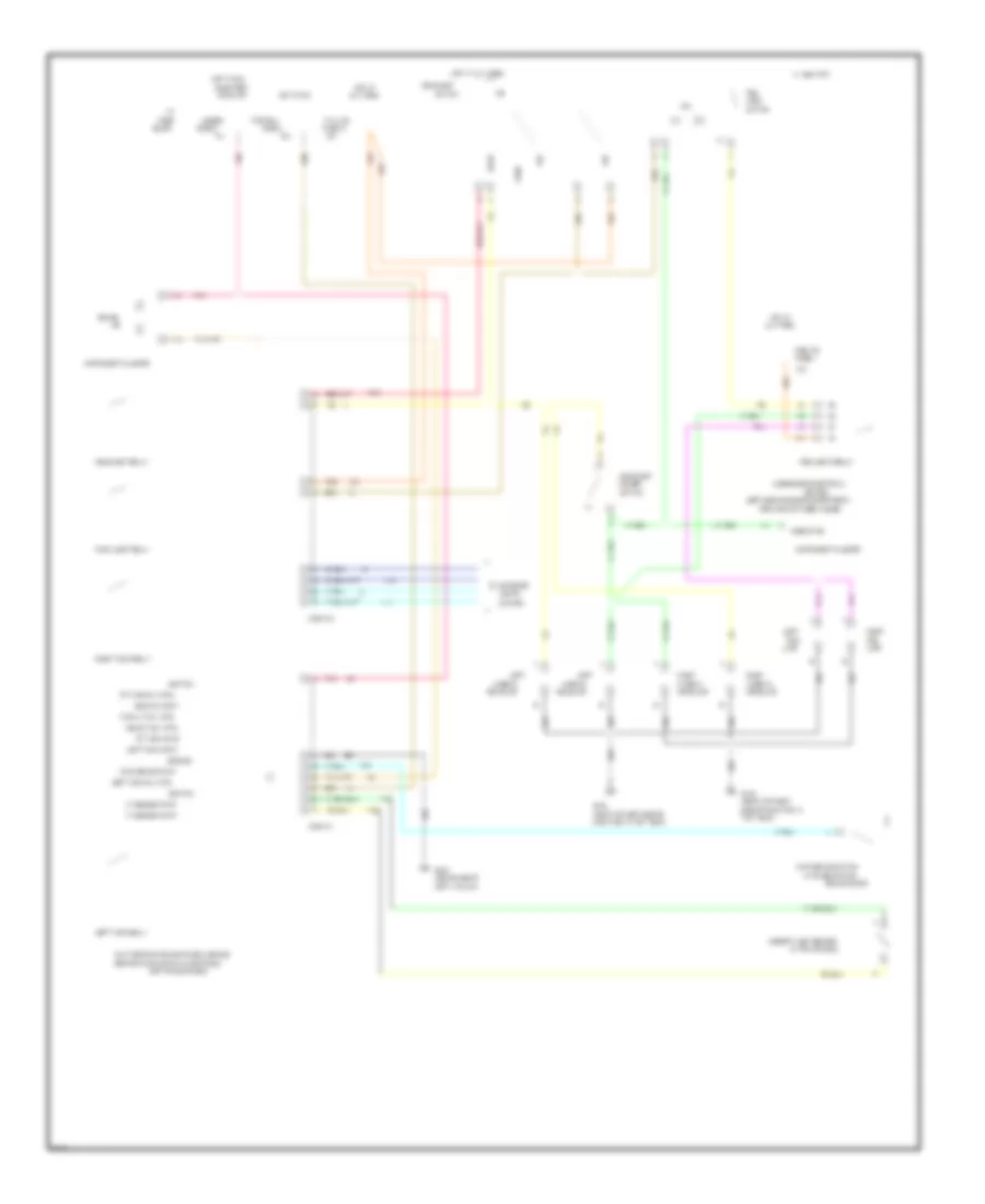
AIR CONDITIONING
A/C Wiring Diagram for Chevrolet Camaro 1995
 https://portal-diagnostov.com/license.html
Automotive Electricians Portal FZCO
Automotive Electricians Portal FZCO
https://portal-diagnostov.com/license.html
https://portal-diagnostov.com/license.html
Automotive Electricians Portal FZCO
Automotive Electricians Portal FZCO
List of elements for A/C Wiring Diagram for Chevrolet Camaro 1995:
- (front of left cylinder head)
- (in underhood electrical center)
- (top right side of engine)
- (v6 vin s, v8 vin p)
- +5v
- A/c clutch diode
- A/c compressor clutch
- A/c compressor relay
- A/c cruise fuse 15a
- A/c evaporator temperature sensor (in evaporator core)
- A/c pressure sensor (above right shock tower)
- A/c request
- Bi-lv
- Blend
- Blower motor
- Blower resistors (in hvac module)
- Blower switch
- C tan
- Center
- Clutch status
- Compressor ctrl
- Coolant fan relay 1 (in underhood electrical center)
- Coolant fan relay 2 (in underhood electrical center) (v8 vin p w/c60, v6 vin k)
- Coolant fan relay 3 (in underhood electrical center) (v8 vin p w/c60, v6 vin k)
- Def
- Engine coolant temperature sensor (front of engine)
- Fan control
- Fans/actr fuse 6 10a
- G108 (near top left side of radiator)
- G110 (v8 vin p, v6 vin k) g120 (v6 vin s)
- G200 (left kick panel)
- G203 (right kick panel)
- Heater-a/c control assembly
- High blower relay (under i/p above left side of floor tunnel)
- Hot at all times
- Hot in run
- Hot in run, bulb test or start
- Htr
- Htr-a/c fuse 25a
- I/p fuse block
- Left coolant fan
- Max
- Mode switch
- Nca
- Norm
- Off
- Pnk
- Powertrain control module (in engine compartment, rear of shock tower)
- Probe (inserted in evaporator)
- Red
- Right coolant fan (v8 vin p w/c60, v6 vin k)
- Sensor ground
- Sensor input
- Solid state
- Tan
- Underhood electrical
- Underhood electrical center
- V6 vin k
- V6 vin k v8 vin p w/c60
- V6 vin s
- V6 vin s v8 vin p
- V6 vin s v8 vin p w/c41
- V8 vin p
- Vent
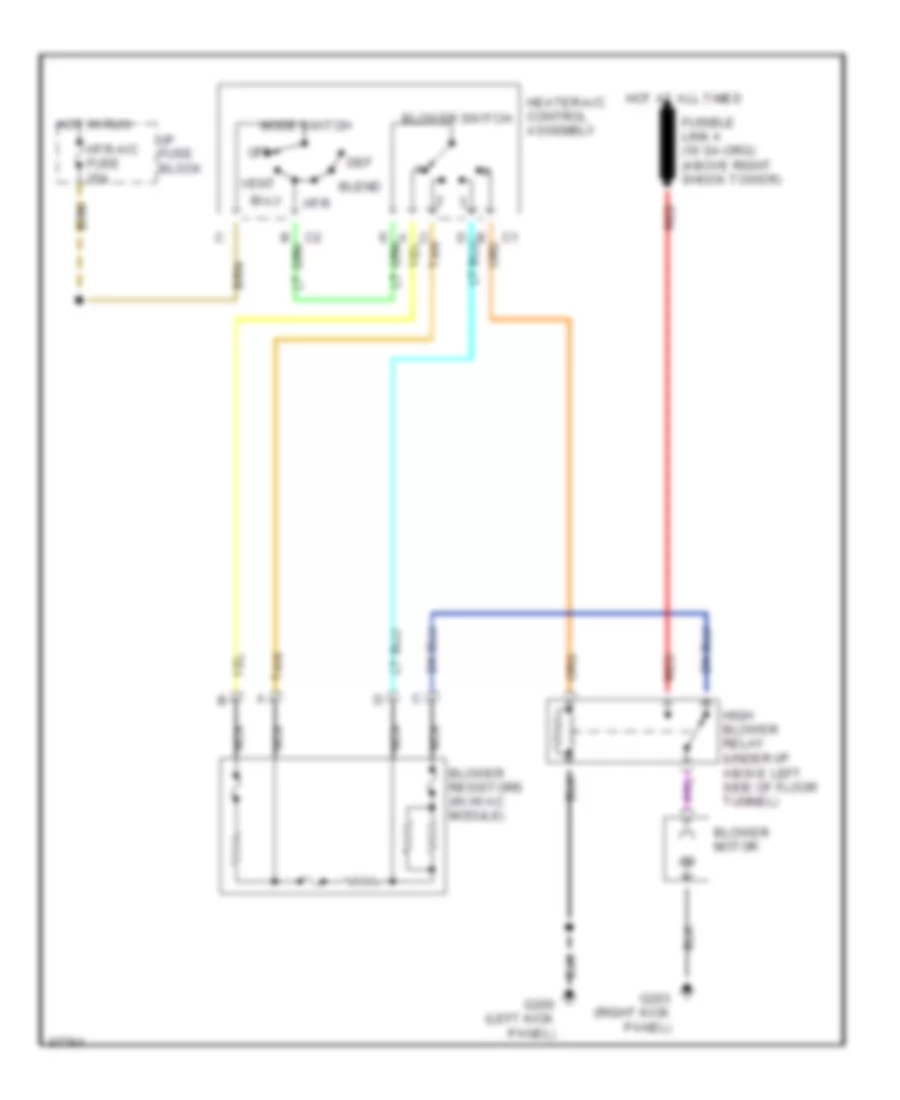
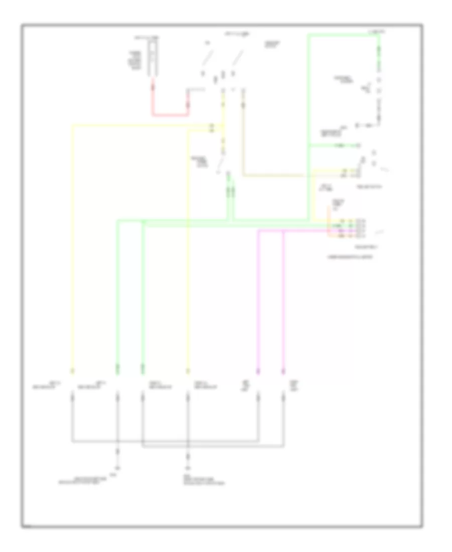
Heater Wiring Diagram for Chevrolet Camaro 1995
List of elements for Heater Wiring Diagram for Chevrolet Camaro 1995:
- Bi-lv
- Blend
- Blower motor
- Blower resistors (in hvac module)
- Blower switch
- C tan
- Def
- G200 (left kick panel)
- G203 (right kick panel)
- Heater-a/c control assembly
- High blower relay (under i/p above left side of floor tunnel)
- Hot at all times
- Hot in run
- Htr
- Htr-a/c fuse 25a
- I/p fuse block
- Mode switch
- Nca
- Off
- Red
- Tan
- Vent
ANTI-LOCK BRAKES
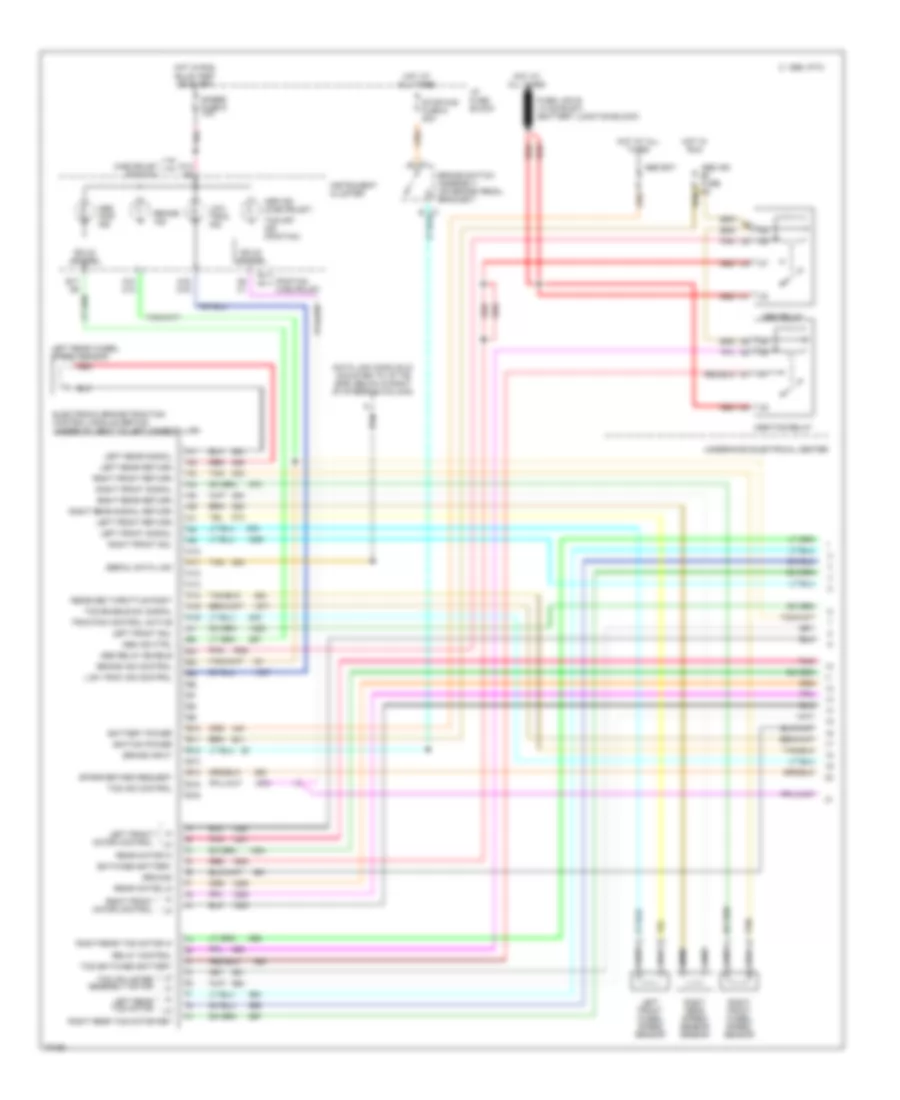
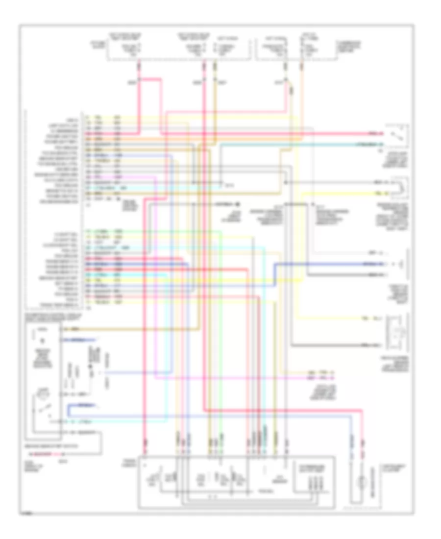
Anti-lock Brake Wiring Diagrams, with Traction Control (1 of 2) for Chevrolet Camaro 1995
List of elements for Anti-lock Brake Wiring Diagrams, with Traction Control (1 of 2) for Chevrolet Camaro 1995:
-
-
-
- A10
- A10 c10
- A11
- A12
- A13
- A14
- A15
- A16
- A16 d16
- A8 c1
- Abs bat
- Abs ind ctrl
- Abs inop ind
- Abs relay
- Abs relay enable
- Asr ind (chevrolet)
- Asr/tcs relay
- B10
- B11
- B12
- B13
- B14
- B15
- B16
- Battery power
- Brake ind
- Brake ind control
- Brake input
- Brake switch assembly (on brake pedal bracket)
- C 1995 vftc
- Chevrolet pontiac
- D13 a5
- Data link conn (dlc) (mounted to i/p tie bar, below & right of steering column)
- Electronic brake/traction control module (ebtcm) (under i/p, next to left hinge pillar)
- Fuse link b (14 ga-rust) (battery junction block)
- Gages fuse 9 10a
- Ground
- Hot at all times
- Hot in run
- Hot in run, bulb test or start
- I/p fuse block
- Ignition power
- Instrument cluster
- Left front motor control
- Left front return
- Left front signal
- Left front sol
- Left front wheel speed sensor
- Left rear return
- Left rear signal
- Left rear tcs motor
- Left rear wheel speed sensor
- Low trac ind
- Low trac ind control
- Pnk
- Pontiac chevrolet
- Rear motor hi
- Rear motor lo
- Received throttle posit
- Red
- Relay control
- Right front motor control
- Right front return
- Right front signal
- Right front sol
- Right front wheel speed sensor
- Right rear return
- Right rear signal return
- Right rear speed sensor sensor
- Right rear tcs motor hi
- Right rear tcs motor ret
- Serial data link
- Solid state
- Spark retard request
- Stop/haz fuse 6 20a
- Switched battery
- Tan
- Tcs adjuster assembly motor
- Tcs enable sw signal
- Tcs ind control
- Tcs off ind (pontiac)
- Tcs switched battery
- Traction control active
- Underhood electrical center
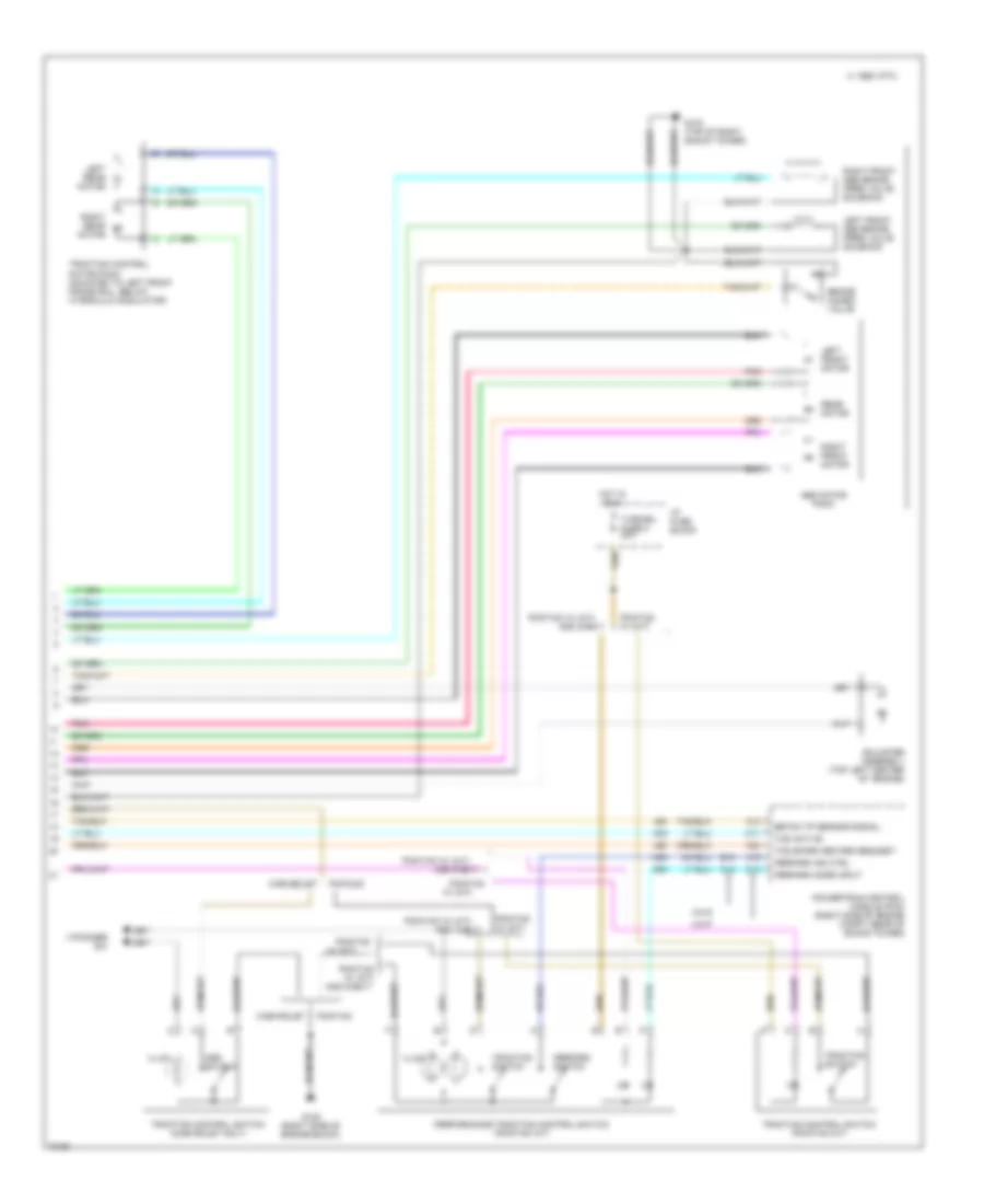
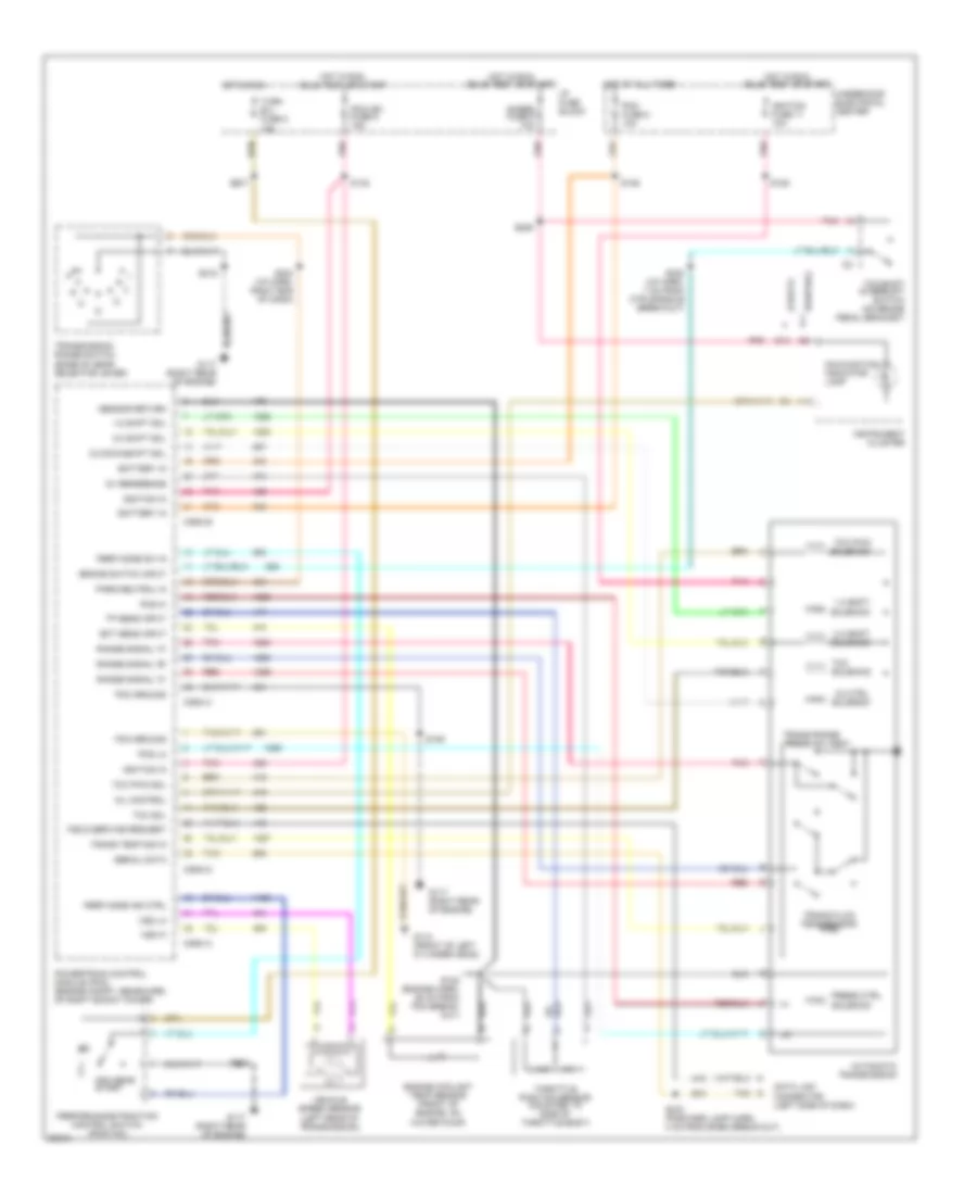
Anti-lock Brake Wiring Diagrams, with Traction Control (2 of 2) for Chevrolet Camaro 1995
List of elements for Anti-lock Brake Wiring Diagrams, with Traction Control (2 of 2) for Chevrolet Camaro 1995:
- A12
- A15
- A23
- Abs motor pack
- Adjuster assembly (top left center of engine)
- And chevy
- Asr switch
- B18
- Brake combo valve
- C 1995 vftc
- C10
- C11
- C13
- Chevrolet
- Ebtcm tp sensor signal
- G103 (top of right shock tower)
- G120 (right side of engine block)
- Hot in run
- I/p dimmer sw
- I/p fuse block
- Illum
- Left front abs brake pres valve solenoid
- Left front motor
- Left rear motor
- Perform ind ctrl
- Perform mode input
- Perform switch
- Performance traction control switch (pontiac a/t)
- Pnk
- Pontiac
- Pontiac w/ (a/t)
- Pontiac w/ (a/t) and chevy
- Pontiac w/ (m/t)
- Powertrain control module (pcm) (right side of engine compt, rear of shock tower)
- Rear motor
- Right front abs brake pres valve solenoid
- Right front motor
- Right rear motor
- Tcs active
- Tcs spark retard request
- Traction control motor pack (mounted to left front frame rail, below hydraulic modulator)
- Traction control switch (chevrolet only)
- Traction control switch (pontiac m/t)
- Traction switch
- Turn/bu fuse 2 20a
- Vin p
- Vin s
- W/ (m/t)
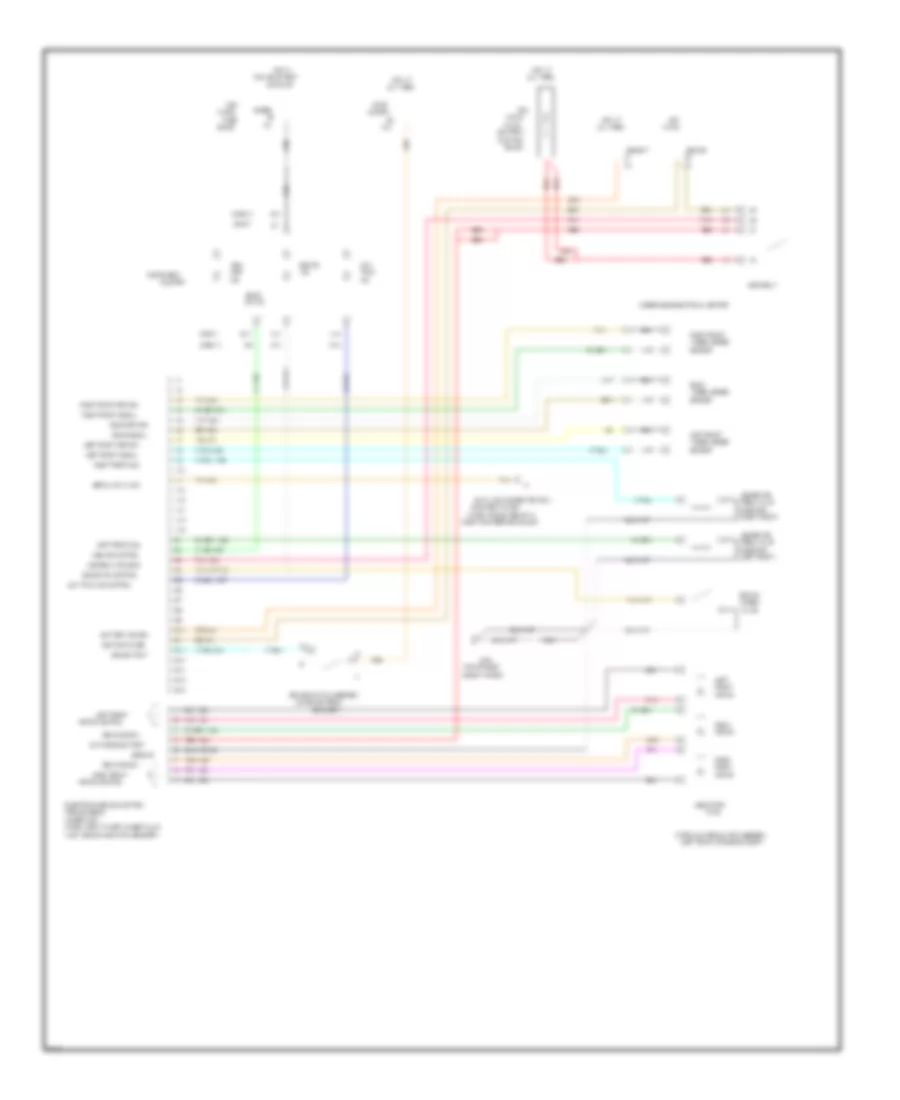
Anti-lock Brake Wiring Diagrams, without Traction Control for Chevrolet Camaro 1995
List of elements for Anti-lock Brake Wiring Diagrams, without Traction Control for Chevrolet Camaro 1995:
- (mounted to inst
- (battery
- (chevy)
- (left front of engine compt)
- (left front)
- (on brake pedal
- (pont)
- (right front)
- (top of right
- (under inst
- 10a
- 2.0 mm
- 20a
- A10
- A11
- A12
- A13
- A14
- A15
- A16
- Abs
- Abs bat
- Abs brake
- Abs ign
- Abs ind control
- Abs motor
- Abs relay
- Abs relay enable
- All times
- B10
- B11
- B12
- B13
- B14
- B15
- B16
- B17
- Battery power
- Block
- Block)
- Bracket)
- Brake
- Brake ind control
- Brake input
- Brake switch assembly
- C10
- Cluster
- Combo
- D13
- D16
- Data link connector (dlc)
- Electronic brake control
- Front
- Fus
- Fuse
- G103
- Gages
- Ground
- Hazard
- Hot
- Hot at
- Hot in
- Hydraulic modulator assembly
- Ignition power
- In run
- Ind
- Inop
- Inst
- Instrument
- Junction
- Just above pass thru grommet)
- Left
- Left front
- Left front return
- Left front signal
- Left front sol
- Link b
- Low
- Low trac ind control
- Module (ebcm)
- Motor
- Motor control
- Or start
- Pack
- Panel
- Panel tie bar, below &
- Panel, next to left hinge pillar,
- Pnk
- Pnk 1281
- Pnk 1632
- Pres valve
- Rear
- Rear motor +
- Rear motor /
- Rear return
- Rear signal
- Red
- Red 1633
- Right
- Right front
- Right front return
- Right front signal
- Right front sol
- Right of steering column)
- Run, bulb test
- Sensor
- Serial data link
- Shock tower)
- Solenoid
- Solid
- State
- Stop/
- Switched battery
- Tan
- Tan 800
- Tan 833
- Trac
- Underhood electrical center
- Valve
- Wheel speed
ANTI-THEFT
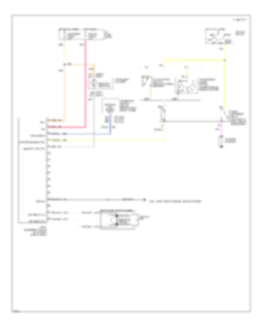
Pass-Key Wiring Diagram for Chevrolet Camaro 1995
List of elements for Pass-Key Wiring Diagram for Chevrolet Camaro 1995:
- "security" indicator
- (chevy)
- (chevy) (pont)
- (mounted to right side of sir bracket)
- (pont)
- (right side of engine, above starter)
- (under console, base of shifter)
- (v6 vin 6) (v8 vin p) (v6 vin k)
- A/t
- A3 a3
- Acc
- Bat
- Bulb test
- C 1995 vftc
- C13
- C14 a13
- C23 a25 a55
- Clutch start switch (on clutch pedal bracket)
- Courtresy fuse 8 15a
- Cranking fuel enable input
- Fuel enable
- G120
- Ground
- Hot at all times
- Hot in run
- I/p fuse block
- Ign
- Ignition key
- Ignition switch
- Instrument cluster
- Key res in (hi)
- Key res in (lo)
- Lock
- M/t
- Off
- Pcm ign fuse 5 15a
- Pnk
- Powertrain control module (rear of right shock tower)
- Resistor pellet
- Run
- Security ind ctrl
- Start
- Starter enable ctrl
- Starter solenoid
- Theft deterrent module (in i/p, right side of radio)
- Theft deterrent relay
- Transmission range switch
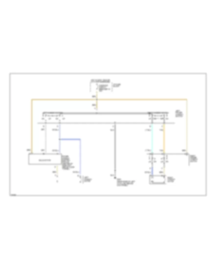
BODY COMPUTER
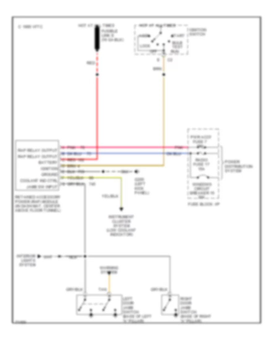
Body Computer Wiring Diagrams for Chevrolet Camaro 1995
List of elements for Body Computer Wiring Diagrams for Chevrolet Camaro 1995:
- 15a
- 1995 vftc c
- Accy
- Battery
- Bulb test
- Coolant ind ctrl
- Fuse 7
- Fuse block: i/p
- G200 (left kick panel)
- Ground
- Hot at all times
- Ignition
- Ignition switch
- Instrument cluster system (low coolant indicator)
- Interior lights system
- Jamb sw input
- Left door jamb switch (base of left "a" pillar)
- Lock
- Nca
- Off
- Pnk
- Power distribution system
- Pwr accy
- Radio fuse 17 15a
- Rap relay output
- Red
- Retained accessory power (rap) module (in dash mat, center above floor tunnel)
- Right door jamb switch (base of right "a" pillar)
- Run
- Start
- Tan
- Warning system
- Windows circuit breaker 15 30a
COMPUTER DATA LINES
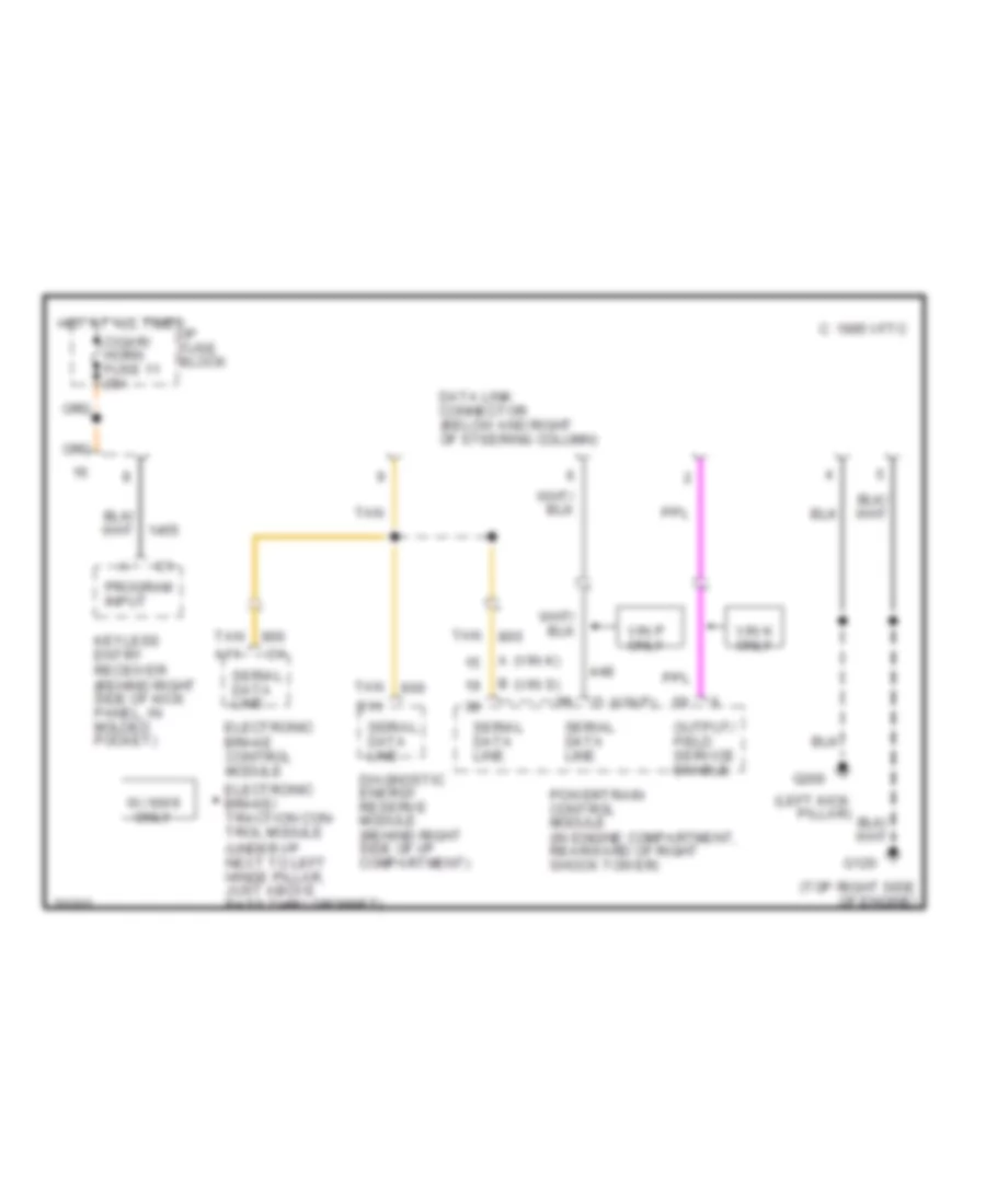
Data Link Connector Wiring Diagram for Chevrolet Camaro 1995
List of elements for Data Link Connector Wiring Diagram for Chevrolet Camaro 1995:
- (left kick pillar)
- (top right side of engine)
- (vin p) d
- A (vin k)
- A11
- B (vin s)
- B11
- C 1995 vftc
- Cigar/ horn fuse 11 25a
- Data link connector (below and right of steering column)
- Diagnostic energy reserve module (behind right side of i/p compartment)
- Electronic brake control module
- Electronic brake/ traction con- trol module (under i/p next to left hinge pillar, just above pass thru grommet)
- G120
- G200
- Hot at all times
- I/p fuse block
- Keyless entry receiver (behind right side of kick panel, in molded pocket)
- Output/ field service enable
- Powertrain control module (in engine compartment, rearward of right shock tower)
- Program input
- Serial data line
- Tan
- Vin k only
- Vin p only
- W/ nw9 only
COOLING FAN
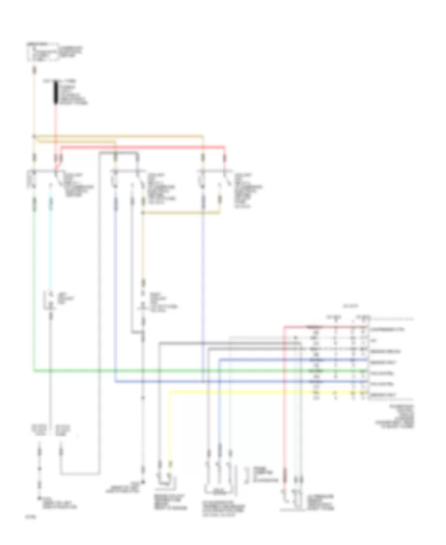
Cooling Fan Wiring Diagram for Chevrolet Camaro 1995
List of elements for Cooling Fan Wiring Diagram for Chevrolet Camaro 1995:
- (v6 vin s, v8 vin p)
- +5v
- A/c evaporator temperature sensor (in evaporator core)
- A/c pressure sensor (above right shock tower)
- Compressor ctrl
- Coolant fan relay 1 (in underhood electrical center)
- Coolant fan relay 2 (in underhood electrical center) (v8 vin p w/c60, v6 vin k)
- Coolant fan relay 3 (in underhood electrical center) (v8 vin p w/c60, v6 vin k)
- Engine coolant temperature sensor (front of engine)
- Fan control
- Fans/actr fuse 6 10a
- G108 (near top left side of radiator)
- Hot at all times
- Hot in run
- Left coolant fan
- Powertrain control module (in engine compartment, rear of shock tower)
- Probe (inserted in evaporator)
- Red
- Right coolant fan (v8 vin p w/c60, v6 vin k)
- Sensor ground
- Sensor input
- Solid state
- Underhood electrical center
- V6 vin k
- V6 vin k v8 vin p w/c60
- V6 vin s
- V6 vin s v8 vin p w/c41
- V8 vin p
CRUISE CONTROL
Cruise Control Wiring Diagram for Chevrolet Camaro 1995
List of elements for Cruise Control Wiring Diagram for Chevrolet Camaro 1995:
- "low trac" ind
- (early production)
- (early production) (late production)
- (late production)
- (v6 vin k)
- (v6 vin s)
- (v8 vin p)
- 4000 pulses/mile
- A c1
- A/c-cruise fuse 12 15a
- A/t
- A13
- A16
- A31
- A32
- Abs/tcs active
- B12
- B28
- B29
- B30
- Brake input
- Brake switch assembly (on brake pedal bracket)
- C 1995 vftc
- C1 c b c1
- Chevrolet
- Clutch anticipate/ cruise release
- Cruise control module (left front side of engine compt)
- Cruise release brake switch (m/t) (v8 vin p) (mounted on brake pedal bracket)
- Cruise release/ brake switch (a/t) (on brake pedal bracket)
- Cruise release/ brake switch (m/t) (on brake pedal bracket)
- Cruise switch
- D13
- D16
- Electronic brake/ traction control module (ebtcm) (under i/p, next to left hinge pillar)
- G100 (bolted to left front frame rail)
- Gages fuse 9 10a
- Ground
- Hazard flasher
- Hot at all times
- Hot in run, bulb test or start
- I/p fuse block
- Ignition input
- Instrument cluster
- M/t
- Multi-function lever
- Nca
- Off
- On/off input
- Pnk
- Pontiac
- Powertrain control module (pcm) (rear of engine compt, behind right shock tower)
- R/a
- Resume/accel input
- Set/ coast sw
- Set/coast input
- Stop/hazard fuse 6 20a
- Switch (m/t) (v6 vin s) (mounted on clutch pedal bracket)
- Underhood electrical center
- Vehicle speed sensor (rear left side of transmission)
- Vss inpt hi
- Vss input
- Vss input lo
- W/ traction control
- W/o traction control
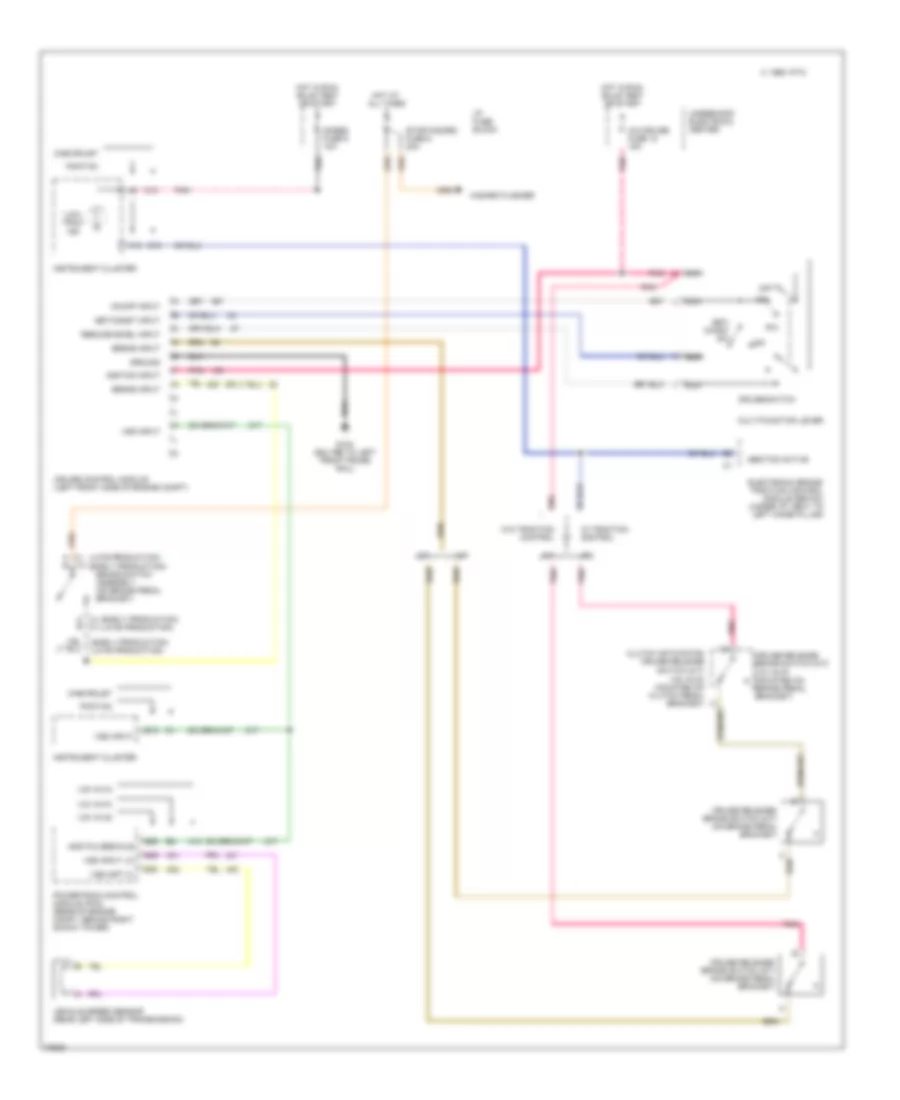
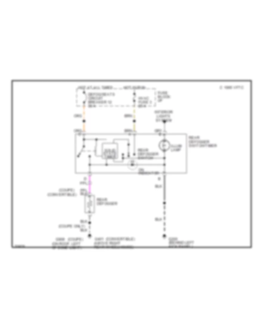
DEFOGGERS
Defogger Wiring Diagram for Chevrolet Camaro 1995
List of elements for Defogger Wiring Diagram for Chevrolet Camaro 1995:
- (convertible)
- (coupe only)
- (coupe)
- (on roof, left of dome light)
- C 1995 vftc
- Defog/seats circuit breaker 12 30 a
- Fuse block: i/p
- G200 (behind left kick panel)
- G401 (above right rear wheelhouse)
- G908
- Hot at all times
- Hot in run
- Hvac fuse 3 25 a
- Illum lamp
- Interior lights system
- On indicator
- Rear defogger
- Rear defogger switch
- Rear defogger switch/timer
- Solid state timer
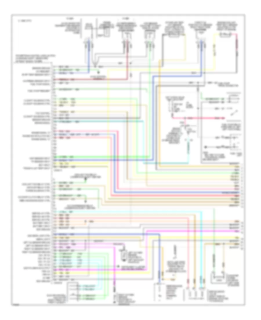
ENGINE PERFORMANCE
3.4L
3.4L (VIN S), Engine Performance Wiring Diagrams (1 of 3) for Chevrolet Camaro 1995
List of elements for 3.4L (VIN S), Engine Performance Wiring Diagrams (1 of 3) for Chevrolet Camaro 1995:
- "service engine soon" ctrl
- (a/t)
- (bolted to floor
- (firebird only)
- (in engine compt, rearward
- (m/t)
- 1-2 shift solenoid ctrl
- 2-3 shift solenoid ctrl
- 2nd gear lamp ctrl
- 3-2 shift solenoid ctrl
- 4000 pulse/mile output
- 5v ref
- A/c comp clutch relay ctrl
- A/c compressor relay (underhood elect center)
- A/c evaporator temperature sensor (mounted in evaporator core)
- A/c press sensor input
- A/c refrigerent pressure sensor (above right shock tower)
- A/c request
- Air pump relay ctrl
- Assembly
- Battery input
- Brake signal
- Brake switch assembly (mounted in lower hole of brake pedal bracket)
- C 1995 vftc
- Canister purge solenoid (left side of engine)
- Coil "a" (hi)
- Coil "a" (lo)
- Coil "b" (hi)
- Coil "b" (lo)
- Conn a
- Conn b
- Coolant fan relay (underhood elect center)
- Coolant fan relay ctrl
- Data link conn (mounted to i/p tie bar, below and right of steering column)
- Drivers seat)
- Ecm ground
- Ect input
- Egr sol #1 ctrl
- Egr sol #2 ctrl
- Egr sol #3 ctrl
- Egr solenoid valve (right side of engine, mounted to manifold)
- Engine coolant temp (ect) sensor (mounted in top front of engine)
- Evap temp sensor input
- Fuel pump prime connector
- Fuel pump relay (forward of left left kick panel)
- Fuel pump request
- Fuel pump signal
- Fuel tank unit
- G300
- Hot in run, bulb test or start
- Hvac control
- I/p fuse block
- Idle air control (iac) motor (right front on throttle body)
- Instrument cluster and cruise control
- Intake air temp (iat) sensor (mounted on air duct, in front of intake manifold)
- Left o2 sensor ground
- Left o2 sensor input
- Left oxygen sensor (mounted in left exhaust mainifold)
- Map sensor (mounted to right side of intake manifold)
- Map sensor input
- Nca
- Of right shock tower)
- Pan bar #2 under
- Pcm ign #5 fuse 15a
- Performance/ traction control switch
- Pnk
- Powertrain control module (pcm)
- Probe (inserted in evaporator)
- Purge solenoid ctrl
- Range sig "b"/clutch sw
- Range signal "a"
- Range signal "c"
- Red
- Right o2 sensor ground
- Right o2 sensor input
- Right oxygen sensor (mounted in right exhaust mainifold)
- Sensor ground
- Serial data
- Solid state
- Tan
- Tcc control
- Tcc switch
- Throttle position (tp) sensor (right front side (of intake)
- Tp sensor input
- Trans fluid temp input
- Vss (hi)
- Vss (lo)
- W/ c60
3.4L (VIN S), Engine Performance Wiring Diagrams (2 of 3) for Chevrolet Camaro 1995
List of elements for 3.4L (VIN S), Engine Performance Wiring Diagrams (2 of 3) for Chevrolet Camaro 1995:
- "service engine soon" indicator
- (camaro)
- (firebird)
- (firebird) (camaro)
- (in engine compt, rearward
- 24x ref signal
- 25a
- 2nd gear start sw
- 3x ref input (hi)
- 3x ref input (lo)
- A/c compressor relay
- A/c status
- A4 c8
- Air pump #7 fuse 20a
- Air pump relay
- C 1995 vftc
- Camshaft sensor signal
- Conn c
- D13
- Data link connector
- Diagnostic enable
- Fans/actr #6 fuse 10a
- Fuel enable input
- Fuel injector #1 ctrl
- Fuel injector #2 ctrl
- Fuel injector #3 ctrl
- Fuel injector #4 ctrl
- Fuel injector #5 ctrl
- Fuel injector #6 ctrl
- G108 (near top left side of radiator)
- G120 (top right side of engine)
- Gages #9 fuse 10a
- Ground
- Hot at all times
- Hot in run, bulb test or start
- I/p fuse block
- Iat sensor input
- Ignition ctrl
- Ignition ctrl bypass
- Ignition input
- Injector #10 fuse 7.5a
- Injector #9 fuse 7.5a
- Instrument cluster
- Knock sensor (in bottom right side of engine block)
- Knock sensor input
- Of right shock tower)
- Pcm #8 fuse 10a
- Pcm ign #5 fuse 15a
- Pnk
- Powertrain control module (pcm)
- Pressure ctrl sol (hi)
- Pressure ctrl sol (lo)
- Red
- Secondary air injection pump assembly (front left frame rail in engine compartment)
- Sensor ref (lo)
- Tan
- Theft deterrent module (in dash, right of radio)
- Underhood electrical center
- Vehicle speed sensor (rear left side of transmission)
3.4L (VIN S), Engine Performance Wiring Diagrams (3 of 3) for Chevrolet Camaro 1995
List of elements for 3.4L (VIN S), Engine Performance Wiring Diagrams (3 of 3) for Chevrolet Camaro 1995:
- (a/t)
- (camaro)
- (firebird)
- (m/t)
- 1-2 shift solenoid
- 2-3 shift solenoid
- 3-2 shift solenoid
- Amp
- Automatic transmission
- B13
- C 1995 vftc
- Camshaft position sensor (in top front of engine block)
- Clutch anticipate switch
- Clutch anticipate/ cruise release sw (mounted in clutch pedal bracket)
- Crankshaft position sensor, hi resolution (lower front of engine block)
- Crankshaft position sensor, low resolution (lower right side of engine block)
- Elect sw
- Ground
- High energy ignition module
- Hot in run, bulb test or start
- Ignition #11 fuse 10a
- Ignition control module (firing order: 1-2-3-4-5-6) (left front of engine)
- Ignition input
- Instrument cluster
- Optical sensor
- Performance/ traction control switch (firebird only)
- Pnk
- Pressure control solenoid
- Primary ctrl
- Red
- Solid state
- Spark plugs
- Tach input
- Tach output
- Tcc pwm solenoid
- Tcc solenoid
- Trans fluid temp sensor
- Underhood electrical center
3.8L
3.8L (VIN K), Engine Performance Wiring Diagrams (1 of 3) for Chevrolet Camaro 1995
List of elements for 3.8L (VIN K), Engine Performance Wiring Diagrams (1 of 3) for Chevrolet Camaro 1995:
- (chevy) (pont)
- (in engine compartment, rearward
- (right side of steering column)
- 2nd gear start ind switch
- 3x ref
- 4k/mi speed
- 5 volt ref a
- 5 volt ref b
- A/c com clutch rel driver
- A/c request
- A1 nca
- Air conditioning system
- B12
- Battery
- Bypass
- C 1995 vftc
- Camshaft pos pcm input
- Conn a
- Cooling fans system
- Cruise control module (front left side of eng compt)
- Cruise control system
- Cruise status
- D13
- Data link connector
- Egr control
- Egr ignition filter
- Evap canister purge driver
- Evap vacuum switch input
- Fan #1 driver
- Fan #2 driver
- Fuel pump (fuel tank unit)
- Fuel pump prime connector (front right of engine compt)
- Fuel pump relay
- Fuel pump relay (position n) (relay center)
- G120 (right side of engine)
- G300 (bolted to floor pan bar #2 under driver's seat)
- Gages fuse 9 10a
- Hot at all times
- Hot in run, bulb test or start
- I/p fuse block
- Iac "a" high
- Iac "a" low
- Iac "b" high
- Iac "b" low
- Idle air control motor (iac) (right front of intake manifold)
- Ignition control
- Ignition feed
- Instrument cluster
- Maf signal
- Malfunction indicator
- Mass air flow (maf) sensor (top front of throttle body)
- Mil driver
- Nca
- Of right shock tower)
- Pcm fuse 8 10a
- Pcm ground
- Pcm ign fuse 5 15a
- Performance/ traction control switch
- Pnk
- Powertrain control module (pcm)
- Reference high
- Reference low
- Sensors ground
- Serial data
- Serial data class 2
- Tan
- Tcc brake switch
- Tcc enable sol driver
- Tcc pwm sol driver
- Theft det fuel enable
- Theft deterrent module (right side of i/p)
- Underhood electrical center (left side of eng compt)
- Vehicle speed sensor (vss) (rear left side of transmission)
- Vss high
- Vss low
3.8L (VIN K), Engine Performance Wiring Diagrams (2 of 3) for Chevrolet Camaro 1995
List of elements for 3.8L (VIN K), Engine Performance Wiring Diagrams (2 of 3) for Chevrolet Camaro 1995:
- (left side of eng compt)
- A pnk
- A/c refrigerant pressure sensor (near right shock tower)
- B tan
- Buffer/ amplifier
- Bypass switch
- C 1995 vftc
- C tan
- Camshaft position sensor (mounted to engine front cover)
- Canister purge vacuum switch
- Coils
- Crankshaft position sensor (lower front of engine)
- Electronic ignition control module (left front of engine)
- Engine coolant temp (ect) sensor (front of lower intake manifold, under throttle body)
- Evaporative emission canister purge solenoid valve (right center of engine)
- Exhaust gas recirculation vacuum control signal solenoid valve (left front of engine)
- G112 (left rear side of engine)
- Hall effect sensor
- Heated oxygen sensor bank 1 sensor 1 (left exhaust manifold)
- Heated oxygen sensor bank 1 sensor 2 (catalytic converter front exhaust tube)
- Heated oxygen sensor bank 1 sensor 3 (catalytic converter rear exhaust tube)
- Heated oxygen sensor bank 2 sensor 1 (right exhaust manifold)
- Hot in run, bulb test or start
- Ignition
- Ignition fuse 11 10a
- Instru- memt cluster
- Instrument cluster system
- Intake air temp (iat) sensor (front of intake manifold)
- Left knock sensor (left side of engine block)
- Manifold absolute pressue (map) sensor (right side of intake manifold)
- Nca
- Pnk
- Right knock sensor (right side of engine block)
- Sensor feed
- Sensor ground
- Spark plugs
- Sws/ amplifier
- Tach
- Throttle position (tp) sensor (right front side of throttle body)
- Underhood electrical center
3.8L (VIN K), Engine Performance Wiring Diagrams (3 of 3) for Chevrolet Camaro 1995
List of elements for 3.8L (VIN K), Engine Performance Wiring Diagrams (3 of 3) for Chevrolet Camaro 1995:
- 1-2 shift solenoid
- 15a
- 2-3 shift solenoid
- 2nd start mode sw sig
- 3-2 control solenoid dr
- 3-2 shift solenoid
- 7.5a
- A/c refrigerant pres sig
- Alternator lamp driver
- Automatic transmission
- Bank 1 ho2s 1 low
- Bank 1 ho2s 1 signal
- Bank 1 ho2s 2 low
- Bank 1 ho2s 2 signal
- Bank 1 ho2s 3 low
- Bank 1 ho2s 3 signal
- Bank 1 ks signal
- Bank 2 ho2s 1 low
- Bank 2 ho2s 1 signal
- Bank 2 ks signal
- Brake switch assembly (on brake pedal support)
- C 1995 vftc
- C c2
- Conn b
- Cruise control system
- Cruise inhibit driver
- D c2
- Ect signal
- Egr pintile position
- Fans/actr fuse 6 10a
- Fuel injectors
- Fuse 10
- Fuse 5
- Fuse 9
- G120 (right side of engine)
- Generator
- Generator control
- Hot in run
- Hot in run, bulb test or start
- I/p fuse block
- Iat signal
- Injector
- Injector cylinder #1
- Injector cylinder #2
- Injector cylinder #3
- Injector cylinder #5
- Injector cylinder #6
- Injector signal #4
- Instrument cluster system
- Map signal
- Pcm ground
- Pcm ign
- Pcs hi
- Pcs low
- Performance/ traction control switch
- Pnk
- Powertrain control module (pcm) (in engine compartment, rearward of right shock tower)
- Pressure control solenoid
- Range signal "a"
- Range signal "b"
- Range signal "c"
- Red
- Shift solenoid a driver
- Shift solenoid b driver
- Tan
- Tcc pwm solenoid
- Tcc solenoid
- Tcc switch
- Tft signal
- Tp signal
- Trans fluid temp sensor
- Underhood electrical center (left side of eng compt)
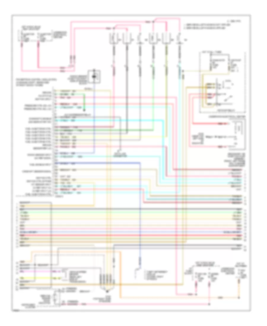
5.7L
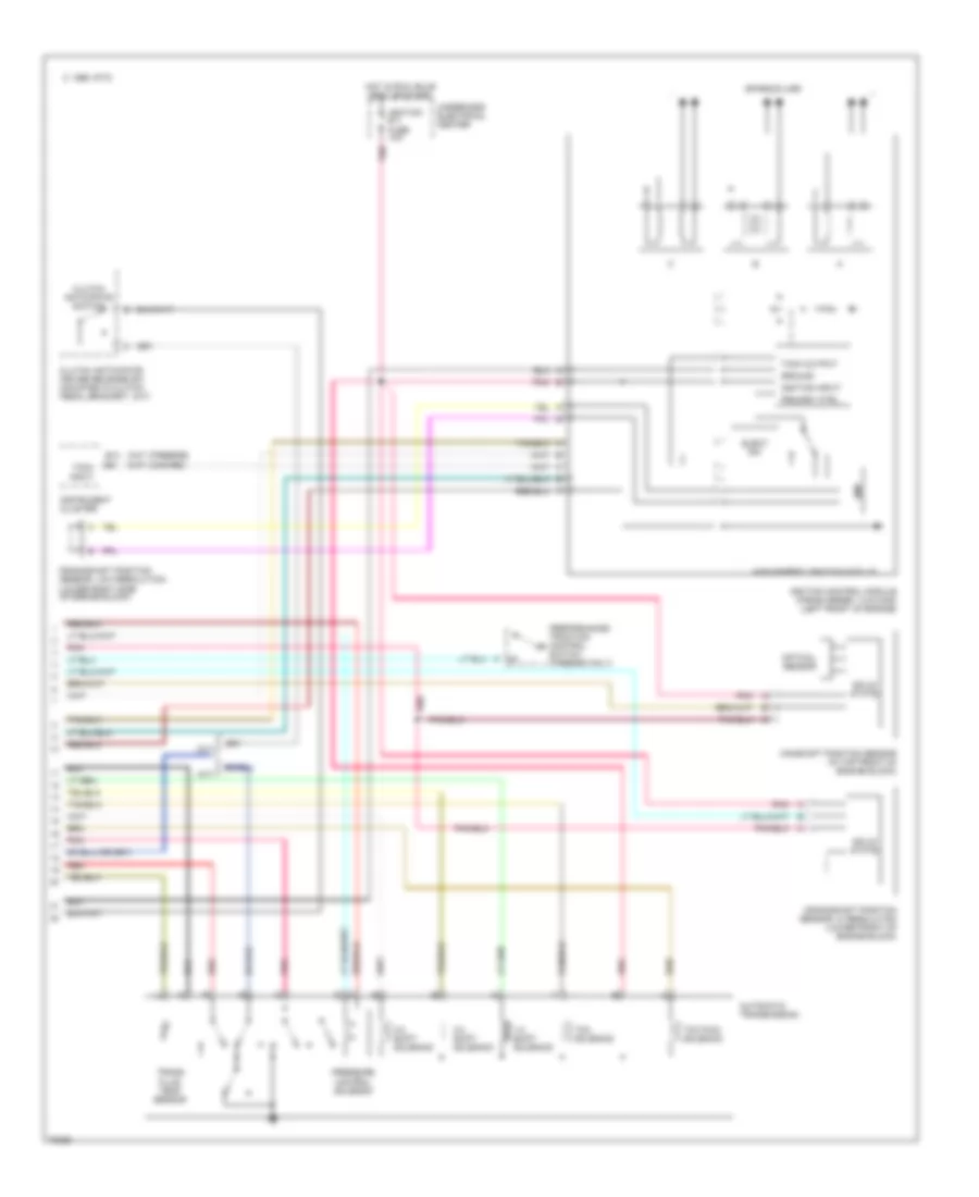
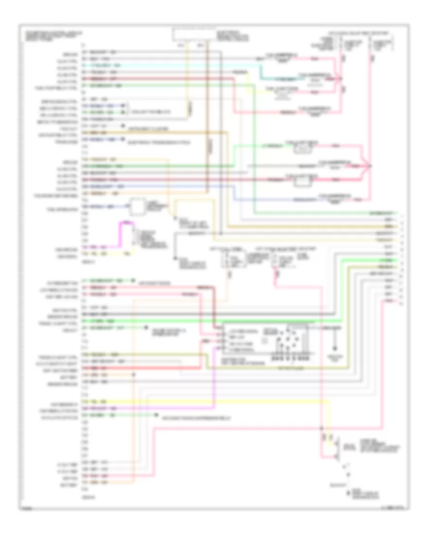
5.7L (VIN P), Engine Performance Wiring Diagrams (1 of 3) for Chevrolet Camaro 1995
List of elements for 5.7L (VIN P), Engine Performance Wiring Diagrams (1 of 3) for Chevrolet Camaro 1995:
- (3-2 a/t)(skip m/t) shift
- 5 volt ref
- A/c clutch status
- A/c request sig
- A14
- Air conditioning
- Air conditioning compressor relay
- Air pump relay ctrl
- B14
- Battery
- C 1995 vftc
- Coil wire
- Conn a
- Conn b
- Coolant fan relays
- Cruise control & speedometer
- Dist ignition feed
- Dist ref low sig
- Distributor (frt center of engine)
- Ebtcm tp sensor sig
- Egr solenoid ctrl
- Electronic brake/traction control module
- Electronic transmission ctrls
- Fuel enable sig
- Fuel injector #1
- Fuel injector #2
- Fuel injector #3
- Fuel injector #4
- Fuel injector #5
- Fuel injector #6
- Fuel injector #7
- Fuel injector #8
- Fuel pump relay ctrl
- Fuse block
- G110 (front of left cylinder head)
- G120 (right side of engine block)
- Ground
- Hi res signal
- High resolution sig
- Hot at all times
- Hot in run, bulb test or start
- Ign voltage
- Ignition
- Ignition coil
- Ignition ctrl
- Inj # 8 ctrl
- Inj #1 ctrl
- Inj #2 ctrl
- Inj #3 ctrl
- Inj #4 ctrl
- Inj #5 ctrl
- Inj #6 ctrl
- Inj #7 ctrl
- Injector fuse 10 7.5a
- Injector fuse 9 7.5a
- Instrument cluster
- Low res signal
- Low resolution sig
- Maf sensor in
- Mass air flow sensor (on air duct in front of intake manifold)
- Optical sensor
- Pcm fuse 8 10a
- Pcm ign fuse 5 15a
- Pnk
- Powertrain control module (rearward of right front shock tower)
- Pri lo spd rly ctrl
- Red
- Ref low
- Sec hi spd rly ctrl
- Sensor ground
- Solid state
- Spark plugs
- Tach out
- Tcs spark retard req
- Theft deterrent module
- Trans 1-2 shift ctrl
- Trans 2-3 shift ctrl
- Trans mode
- Under- hood electrical center
- Underhood electrical center
- Vehicle speed sensor (left rear of transmission)
- Vss ground
- Vss out
- Vss signal
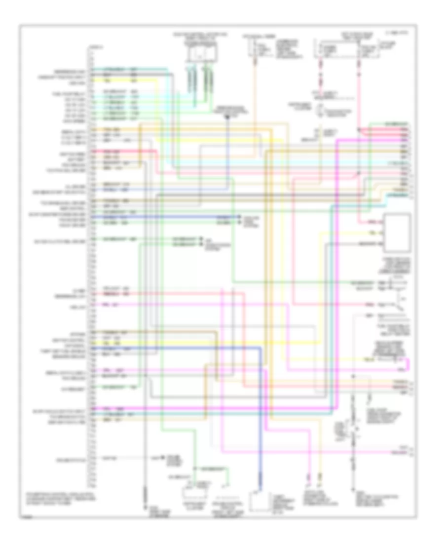
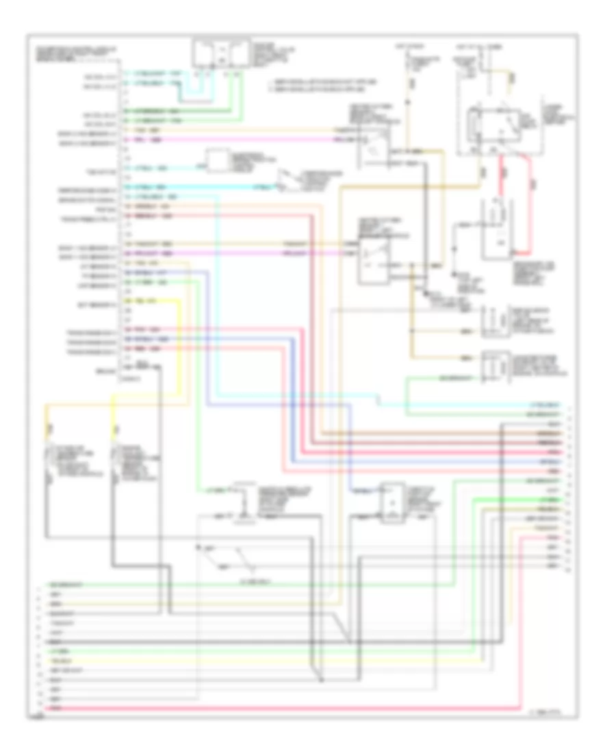
5.7L (VIN P), Engine Performance Wiring Diagrams (2 of 3) for Chevrolet Camaro 1995
List of elements for 5.7L (VIN P), Engine Performance Wiring Diagrams (2 of 3) for Chevrolet Camaro 1995:
- 20a
- 25a
- A16
- Air pump
- Air pump relay
- Bank 1 h02 sensor lo
- Bank 1 ho2 sensor hi
- Bank 2 ho2 sensor hi
- Bank 2 ho2 sensor lo
- Brake switch signal
- C 1995 vftc
- Canister purge solenoid valve (right center of engine, on manifold)
- Conn c
- Ect sensor in
- Egr solenoid valve (left rear of engine, on intake plenum)
- Electronic brake/traction control module
- Engine coolant temperature sensor (front of engine, in water pump)
- Fans/actr fuse 6 10a
- Fuse 7
- G108 (top left side of radiator)
- G112 (front of left cylinder head
- Ground
- Heated oxygen sensor 1 (bank 1, left exhaust manifold)
- Heated oxygen sensor 2 (bank 2, right exhaust manifold)
- Hot at all times
- Hot in run
- Iac coil a hi
- Iac coil a lo
- Iac coil b hi
- Iac coil b lo
- Iat sensor in
- Idle air control valve (right front of throttle body)
- Intake air temperature sensor (on air duct, in front of intake manifold)
- Manifold absolute pressure sensor (right side of intake manifold) a
- Map sensor in
- Performance mode in
- Performance/ traction control switch
- Pnk
- Pnp sig
- Powertrain control module (rearward of right front shock tower)
- Red
- Secondary air injection pump assembly (front left frame rail)
- Tan
- Tcs active
- Throttle position sensor (right front of intake) a
- Tp sensor in
- Trans press ctrl hi
- Trans range sig a
- Trans range sig b
- Trans range sig c
- Under- hood electrical center
- W/ c60 only
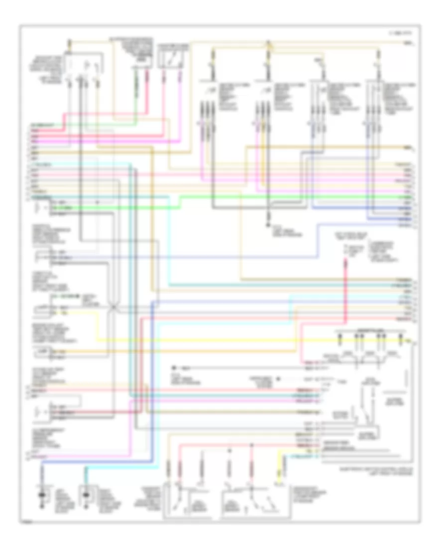
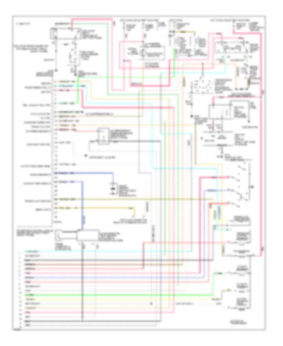
5.7L (VIN P), Engine Performance Wiring Diagrams (3 of 3) for Chevrolet Camaro 1995
List of elements for 5.7L (VIN P), Engine Performance Wiring Diagrams (3 of 3) for Chevrolet Camaro 1995:
- (a/t only)
- (camaro)
- (camaro) (firebird)
- (firebird)
- (in console)
- (left middle of trans)
- (left rear of trans)
- (m/t only)
- (near derm breakout)
- (on base of shift control lever)
- (right of steering column)
- (top rear of right front
- 1-2 shift solenoid
- 2-3 shift solenoid
- 3-2 ctrl solenoid (pwm)
- A/c clutch ctrl
- A/c compressor relay
- A/c evap temp sens in
- A/c evaporator temp sensor (mounted in evaporator core)
- A/c press sensor in
- A/c refrigerant pressure sensor (above right shock tower)
- Automatic transmission
- Brake switch assem- bly
- Brake trans shift inter- rupt solenoid
- Btsi switch
- C 1995 vftc
- Canister purge ctrl
- Cluster
- Coil driver
- Conn d
- D13
- Data link connector
- Distributor
- Fans/actr fuse 6 10a
- Fuel pump prime connector
- Fuel pump relay (forward of left kick panel)
- Fuel pump/ level sender (in fuel tank)
- Fuse block
- G110 (front of left cylinder head)
- G120 (right side of engine block)
- G300 (under drivers seat)
- Gages fuse 9 10a
- Ground
- Hei coil wire
- Hot in run
- Hot in run, bulb test or start
- Ign
- Ign ctrl
- Ignition
- Ignition coil (front left side of engine)
- Ignition coil module (front left side of engine)
- Ignition fuse 11 10a
- Instru-
- Instrument cluster
- Isolation diode
- Knock sensor (bottom right side of engine block)
- Knock sensor in
- Malfunction indicator
- Ment
- Mil ctrl
- Output/field serv enbl
- Pcm ign fuse 5 15a
- Pnk
- Pnk/
- Powertrain control module (rearward of right front shock tower)
- Pressure control solenoid
- Probe (inserted in evaporator)
- Red
- Rev lock- out sole- noid
- Rev lockout sol ctrl
- Serial data
- Shock tower)
- Skip shift ind ctrl
- Skip shift sole- noid
- Tan
- Tcc solenoid
- Tcc switch
- Trans fluid temp sensor
- Trans fluid temp sig
- Trans press ctrl lo
- Trans tcc ctrl
- Transmission position switch
- Under- hood electrical center
EXTERIOR LIGHTS
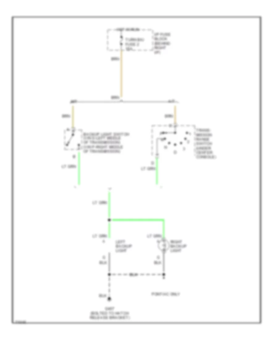
Back-up Lamps Wiring Diagram for Chevrolet Camaro 1995
List of elements for Back-up Lamps Wiring Diagram for Chevrolet Camaro 1995:
- A/t
- Backup light switch (vin s-left middle of transmission) (vin p-right middle of transmission)
- G407 (bolted to hatch release bracket)
- Hot in run
- I/p fuse block (behind right i/p)
- Left backup light
- M/t
- Pontiac only
- Right backup light
- Trans- mission range switch (under center console)
- Turn b/u fuse 2 15a
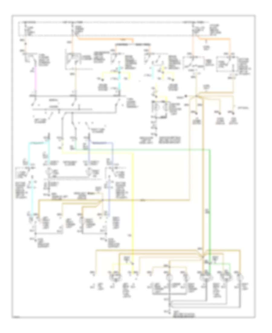
Exterior Light Wiring Diagram, with DRL for Chevrolet Camaro 1995
List of elements for Exterior Light Wiring Diagram, with DRL for Chevrolet Camaro 1995:
- (base of left
- (bolted to hatch release bracket)
- (chevy) (pont)
- A pillar)
- Audio alarm module
- B14
- Brake switch assembly (on brake pedal bracket)
- C15
- C4 b3
- Center high mounted stop light
- Convenience center (left of steering column)
- Cruise control system
- Ctrl
- Daytime running lights module (behind i/p, left of i/p compt)
- Early prod.
- Fog light switch
- G108 (left radiator support)
- G109 (right radiator support)
- G407
- G408-convertible (bolted to hatch release bracket)
- G900
- G902-coupe (left of dome light)
- Hazard
- Hazard flasher
- Head
- Head- light switch
- Headlight doors module
- Hot at all times
- Hot in run
- I/p dimmer switch
- I/p fuse block (behind left side of i/p)
- Instrument cluster
- L turn lamps ctrl
- Lamps
- Late prod.
- Left front marker light
- Left front park/ turn light
- Left rear marker light
- Left rear tail/ stop/ turn lights
- Left tail light
- Left turn & hazard
- Left turn ind.
- License light
- Nca
- Normal
- Off
- Optional
- Park
- Park lamps ctrl
- Pont only
- R turn
- Radio
- Right front marker light
- Right front park/ turn light
- Right rear marker light
- Right rear tail/ stop/ turn lights
- Right tail light
- Right turn & hazard
- Right turn ind.
- Stop/ hazard fuse 6 20a
- Tail lts fuse 10 20a
- Turn b/u fuse 2 15a
- Turn flasher (right of steering column)
- Turn/ hazard switch assembly
- W/drl only
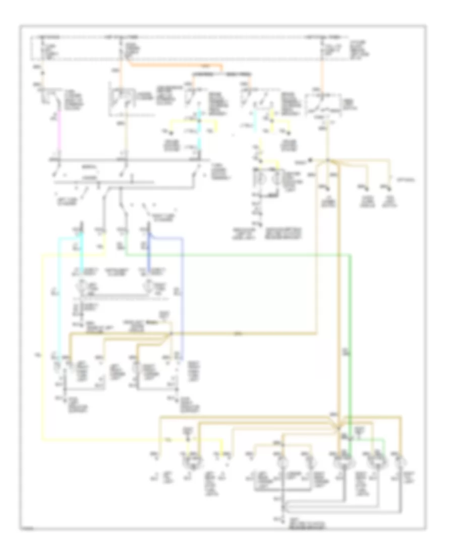
Exterior Light Wiring Diagram, without DRL for Chevrolet Camaro 1995
List of elements for Exterior Light Wiring Diagram, without DRL for Chevrolet Camaro 1995:
- (base of left
- (bolted to hatch release bracket)
- (chevy) (pont)
- A pillar)
- Audio alarm module
- B14
- Brake switch assembly (on brake pedal bracket)
- C15
- C4 b3
- Center high mounted stop light
- Convenience center (left of steering column)
- Cruise control system
- Early prod.
- Fog light switch
- G108 (left radiator support)
- G109 (right radiator support)
- G407
- G408-convertible (bolted to hatch release bracket)
- G900
- G902-coupe (left of dome light)
- Hazard
- Hazard flasher
- Head
- Head- light switch
- Headlight doors module
- Hot at all times
- Hot in run
- I/p dimmer switch
- I/p fuse block (behind left side of i/p)
- Instrument cluster
- Late prod.
- Left front marker light
- Left front park/ turn light
- Left rear marker light
- Left rear tail/ stop/ turn lights
- Left tail light
- Left turn & hazard
- Left turn ind.
- License light
- Nca
- Normal
- Off
- Optional
- Park
- Pont only
- Radio
- Right front marker light
- Right front park/ turn light
- Right rear marker light
- Right rear tail/ stop/ turn lights
- Right tail light
- Right turn & hazard
- Right turn ind.
- Stop/ hazard fuse 6 20a
- Tail lts fuse 10 20a
- Turn b/u fuse 2 15a
- Turn flasher (right of steering column)
- Turn/ hazard switch assembly
GROUND DISTRIBUTION
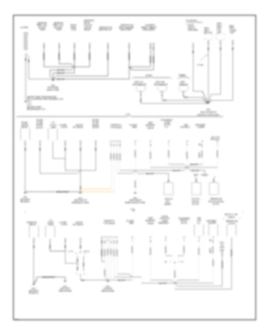
Ground Distribution Wiring Diagram (1 of 3) for Chevrolet Camaro 1995
List of elements for Ground Distribution Wiring Diagram (1 of 3) for Chevrolet Camaro 1995:
- (a/t)
- (bolted to belt tension bracket
- (bolted to right
- (dlc)
- (left front
- (left front of
- (near top right of
- (pontiac w/ m30
- (right side of
- (top of right
- (top right
- (v8 vinp only)
- (w/ t96)
- A/c
- A/c
- A/c comp
- A/t
- A12
- A18
- Abs brake
- Anticipate
- B15
- B16
- B20
- B23
- B32
- Bank #1
- Bank #2
- Battery
- Beam headlamp
- Bolt lower right front of engine (vin s))
- Brake
- Brake/
- C17
- C32
- Camaro
- Chevy
- Chevy pontiac
- Cluster
- Clutch
- Coil module
- Combo
- Compartment
- Conn
- Conn (dlc)
- Control
- Coolant
- Cruise
- Cruise ctrl
- Ctrl module
- Data
- Data link
- Deterrent
- Diagnostic
- Diode
- Discriminating
- Electronic
- Energy reserve
- Engine
- Engine above starter)
- Engine below head)
- Firebird
- Flow
- Fog lamp
- Frame rail)
- Front
- Fuel
- G100
- G103
- G109
- G110
- G112
- G119
- G120
- Ground strap
- Headlamp
- Heated
- Ignition
- Instrument
- Lamp
- Level sens
- Link
- M/t
- Marker
- Mass air/
- Module
- Module (derm)
- Nca
- Oil level
- Oxygen
- Park/
- Performance
- Pontiac
- Position
- Powertrain
- Pres valve
- Pump
- Pump relay
- Radiator in top of t/bar)
- Range
- Release sw
- Right
- Right high
- Right low
- Rly
- Sens
- Sens forward
- Sens passenger
- Sensor
- Shock tower)
- Side of engine (vin p))
- Side of engine)
- Sol left
- Sol right
- Switch
- Theft
- Traction
- Traction/control
- Transmission
- Turn
- Valve
- Vin p
- Vin s
- W/ a/c
- W/o a/c
- W/o nw9)
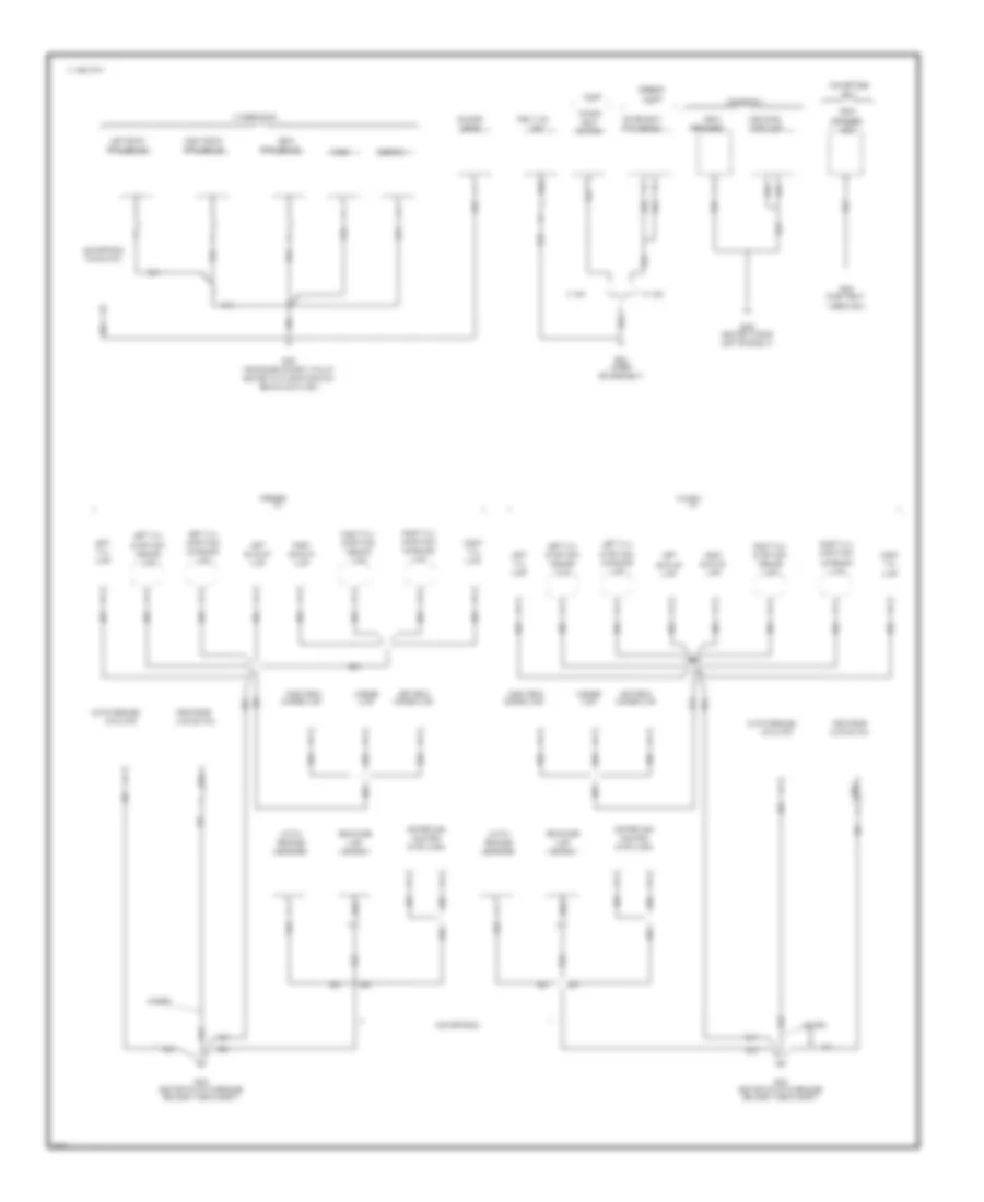
Ground Distribution Wiring Diagram (2 of 3) for Chevrolet Camaro 1995
List of elements for Ground Distribution Wiring Diagram (2 of 3) for Chevrolet Camaro 1995:
- & nw9)
- (a/t)
- (camaro)
- (chevy
- (derm)
- (firebird
- (firebird w/
- (firebird)
- (left rear side
- (near base of left a pillar
- (near top left
- (optional)
- (right side
- (w/ t96)
- (w/ z49)
- (w/o au3 (w/au3)
- (w/o bose)
- (w/v8 vin p
- A (pont)
- A/c
- A21
- A60
- Accessory
- Air injection
- Alarm
- Amplifier
- And c60
- Antenna
- Ashtray
- Assy
- Audio
- B15
- B21
- B60
- Beam headlamp
- Behind kick panel)
- Belt switch
- Bolted to i/p mounting stud
- C 1995 vftc
- Camaro
- Center
- Cigar
- Cluster
- Clutch
- Coil
- Compartment
- Compressor
- Compt
- Connector
- Console
- Control
- Coolant
- Courtesy/
- Ctrl radio
- Data link
- Daytime
- Defog switch
- Deterrent
- Diagnostic
- Dimmer
- Diode
- Door
- Doors
- Electrical
- Energy
- Entry
- Fan
- Firebird
- Flow
- Fog lamp
- Front
- Fuel
- G108
- G112
- G120
- G200
- H (chevy)
- Headlamp
- Heated
- High blower
- Hvac
- I/p
- Ignition
- Illumination
- In top of t-bar)
- Instrument
- Keyless
- Lamp
- Lamp (a/t)
- Lamp (m/t)
- Lamps
- Latch
- Left
- Left front
- Left high
- Left low
- Left mfld
- Level
- Lighter
- Lights (drl)
- Lock
- M30 w/o nw9)
- Marker
- Mass air
- Mirror
- Module
- Motor
- Motor assembly
- Nca
- Of engine)
- Oil
- Oxygen
- Park/turn lamp
- Performance
- Performance/
- Post conv
- Power
- Powertrain
- Pre conv
- Pressure
- Prndl
- Pump
- Pump assembly
- Radio
- Range
- Reading
- Rear
- Rear defog
- Receiver
- Relay
- Reserve
- Retained
- Right
- Right mfld
- Running
- Seat
- Secondary
- Sensor
- Side of radiator
- Sir
- Steering wheel
- Switch
- Switch/timer
- Theft
- Timer/relay
- Traction
- Traction control
- Transmission
- Underhood
- V6 vin s
- V8 vin p
- V8 vin p)
- Vin k
- W/ c41
- W/ c60)
- W/ m30
- W/ nw9)
- W/ v8 vin p
- Washer
- Window
- Wiper
Ground Distribution Wiring Diagram (3 of 3) for Chevrolet Camaro 1995
List of elements for Ground Distribution Wiring Diagram (3 of 3) for Chevrolet Camaro 1995:
- (bolted to hatch release
- (bolted to roof
- (convertible)
- (coupe)
- (near base of right a pillar
- (right rear
- (under
- Actuator
- Back-up
- Behind kick panel)
- Blower
- Bolted to i/p mounting stud
- Bose rly
- Bracket in rear compt)
- C 1995 vftc
- Camaro
- Center high
- Convertible
- Coupe only
- Ctrl module
- Defog grid
- Defogger
- Drivers seat)
- Firebird
- Fuel tank
- G203
- G300
- G403
- G405
- G909
- Grid
- Hatch
- Hatch release
- High level
- Inboard
- Lamp
- Lamp switch
- Left
- Left front
- Left of dome lt)
- Left rear
- Left tail/
- License
- Marker lamp
- Motor
- Mounted
- Nca
- Only
- Outboard
- Power
- Power seat
- Radio
- Rear
- Rear dome
- Release
- Right
- Right front
- Right rear
- Right tail/
- Seat
- Speaker/amp
- Stop lamp
- Stop lamps
- Stop/turn
- Switch
- Tail
- Top switch
- Unit
- W/ ag1
- W/ aq9
- W/ bose radio
- Wheelwell)
HEADLIGHTS
Headlight Wiring Diagram, with DRL for Chevrolet Camaro 1995
List of elements for Headlight Wiring Diagram, with DRL for Chevrolet Camaro 1995:
- 20a
- (at base of park
- (behind radio and hvac controls,
- (in top of dash)
- (left side of engine comprtment,
- (near base of
- (near top left side of
- (near top right
- 10a
- 20a
- All times
- Ambient light sensor
- Block
- Brake
- Brake lever)
- Bulb test
- C 1995 vftc
- C10
- C11
- Center
- Conn c1
- Conn c2
- D13
- Daytime running lights (drl) module
- Dimmer
- Exterior
- Fog
- Fog lights relay
- Fog lts
- Forward of wheel house)
- Fuse
- Fuse 10
- Fuse 2
- Fuse 9
- G108
- G109
- G200
- Gages
- Ground
- Head
- Head on input
- Headlamp
- Headlight
- Headlight relay
- Headlt rly ctrl
- Hi beam
- Hi beam ind
- Hot at
- Hot at all times
- Hot in run
- Hot in run,
- I/p
- Ignition
- Ind
- Instrument cluster
- Lamp
- Left
- Left a pillar)
- Left of glove box)
- Left turn input
- Left turn relay
- Left turn rly ctrl
- Light
- Lights
- Lo beam
- Lt sensor input
- Off
- Or start
- Park
- Park brake input
- Park brake switch
- Park light relay
- Park lt rly ctrl
- Pnk
- Radiator, in top t-bar)
- Right
- Right turn relay
- Rt turn input
- Rt turn rly ctrl
- Side of radiator, in
- Switch
- System
- Tail lts
- Top t-bar)
- Turn b-u
- Underhood electrical
Headlight Wiring Diagram, without DRL for Chevrolet Camaro 1995
List of elements for Headlight Wiring Diagram, without DRL for Chevrolet Camaro 1995:
- g108
- (battery
- (near base of
- (near top of left side
- (near top right side
- 20a
- All times
- Beam
- Beam headlamp
- Block)
- C 1995 vftc
- C11
- Cluster
- Dimmer
- Fog
- Fog light relay
- Fog light switch
- Fog lts
- Fuse 2
- Fusible
- G109
- G200
- Head
- Headlight
- Hot at
- Hot at all times
- Ind
- Instrument
- Junction
- Left
- Left a pillar)
- Left hi
- Left lo
- Light
- Link z
- Of radiator, in top of t-bar)
- Off
- Park
- Red
- Right
- Right hi
- Right lo
- Switch
- Underhood electrical center
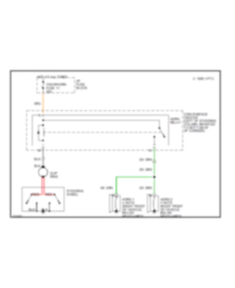
HORN
Horn Wiring Diagram for Chevrolet Camaro 1995
List of elements for Horn Wiring Diagram for Chevrolet Camaro 1995:
- C 1995 vftc
- Cigar/horn fuse 11 25a
- Convenience center (left of steering column, mounted to bottom of i/p carrier)
- Horn 1 a note (right front of vehicle, below headlamps)
- Horn 2 f note (right front of vehicle, below headlamps)
- Horn relay
- Hot at all times
- I/p fuse block
- Red
- Slip ring
- Steering wheel
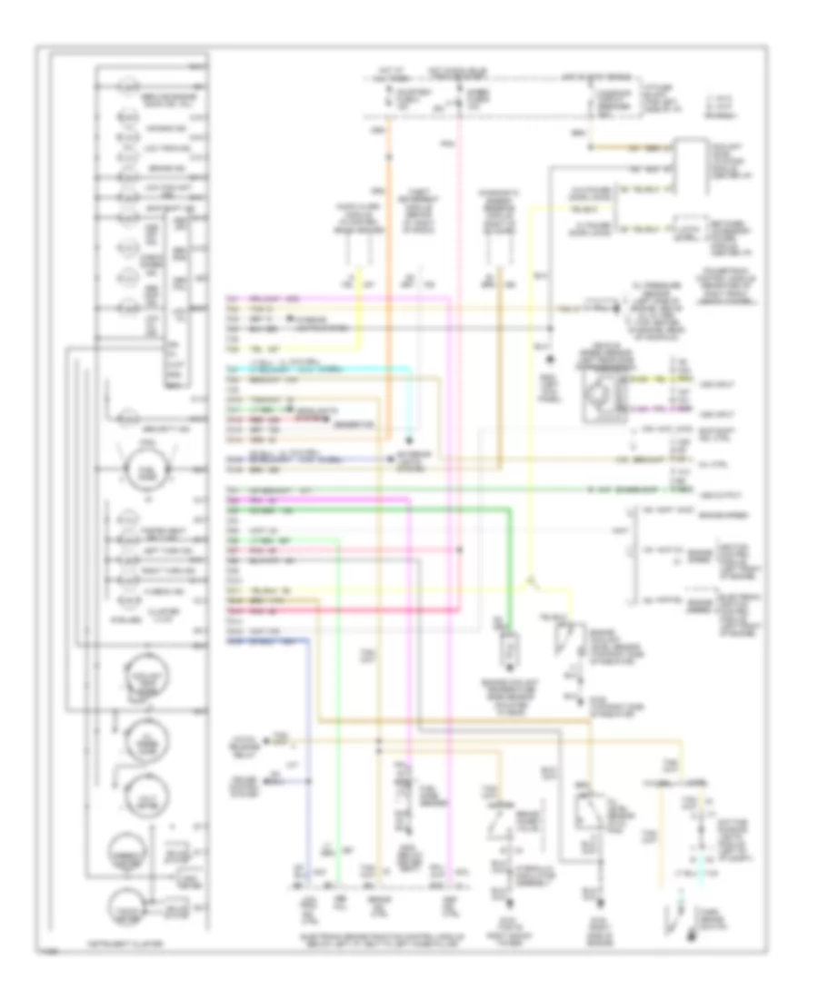
INSTRUMENT CLUSTER
Instrument Cluster Wiring Diagram for Chevrolet Camaro 1995
List of elements for Instrument Cluster Wiring Diagram for Chevrolet Camaro 1995:
- (6 bulbs)
- (below driver seat)
- (left kick panel)
- (right side of engine)
- (top of right shock tower)
- (w/drl)
- (w/o drl)
- A13
- A28
- A31
- A32
- A47
- Abs fail
- Abs inop ind.
- Air bag ind.
- Asr ind. ctrl
- Asr off
- Asr off ind.
- Audio alarm module (in conven- ience center)
- B15
- B28
- B29
- B30
- Bat
- Brake
- Brake combo valve
- Brake ind.
- C10
- C11
- C12
- C13
- C14
- C15
- C16
- Check gages ind.
- Clnt
- Cluster illum.
- Coolant level latching module (center i/p)
- Coolant temp gage
- Courtesy fuse 8 15a
- Cruise control system
- D10
- D11
- D12
- D13
- D14
- D15
- D16
- Daytime running lights module (left of i/p compt)
- Diagnostic energy reserve module (right of i/p compt)
- Electronic brake/traction control module (below left i/p, next to left hinge pillar)
- Electronic ignition control module (left front of engine)
- Engine coolant level sensor (top right side of radiator)
- Engine coolant temperature gage sensor (mounted in head)
- Engine speed
- Exterior lights system
- Fasten seat belt ind.
- Fuel gage
- Fuel gage sender
- G103
- G109 (top right side of radiator)
- G120
- G200
- G300
- Gages fuse 9 10a
- Gen sns
- Generator
- Gnd
- Hatch release relay
- Headlights system
- Hi beam ind.
- Hot at all times
- Hot in accy or run
- Hot in run, bulb test or start
- Hydraulic modulator assembly
- I/p fuse block (far left side of i/p)
- Ign
- Ignition control module (left front of engine)
- Ind. ctrl
- Instrument cluster
- Interior lights system
- Latch ctrl
- Left turn ind.
- Low coolant ind.
- Low oil
- Low oil ind.
- Low trac ind.
- Low trac ind. ctrl
- M/t
- Mil ctrl
- Nca
- Odo- meter
- Oil
- Oil level sensor (in oil pan)
- Oil press gage
- Oil pressure sensor (left side of engine, above oil filter) (top center of engine, rear of manifold)
- Park brake switch
- Pnk
- Powertrain control module (rearward of right front shock tower)
- Red
- Retained accessory power module (center i/p)
- Right turn ind.
- Security ind.
- Service engine soon ind. (mil)
- Skip shift ind.
- Skip shift ind. ctrl
- Solid state
- Speedo- meter
- Tacho- meter
- Tan
- Theft deterrent module (behind i/p, right of radio)
- Vehicle speed sensor (left rear side of transmission)
- Vin k
- Vin p
- Vin s
- Volt- meter
- Vss input
- Vss output
- W/ power door locks
- W/drl
- W/o drl
- W/o power door locks
- Windows circuit breaker 30a
INTERIOR LIGHTS
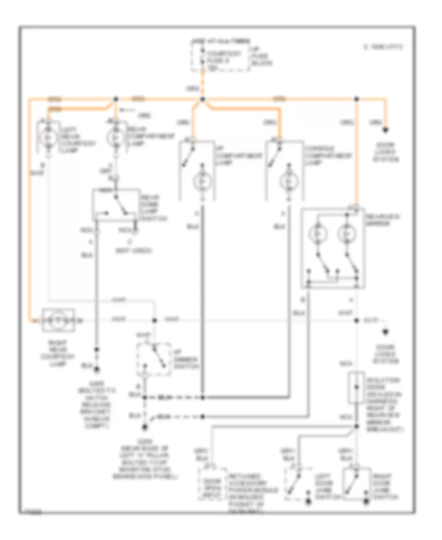
Courtesy Lamp Wiring Diagram, Convertible for Chevrolet Camaro 1995
List of elements for Courtesy Lamp Wiring Diagram, Convertible for Chevrolet Camaro 1995:
- (not used)
- C 1995 vftc
- Console compartment lamp
- Courtesy fuse 8 15a
- Door locks system
- Door open input
- G200 (near base of left "a" pillar, bolted to i/p mounting stud behind kick panel)
- G405 (bolted to hatch release bracket, in rear compt)
- Hot at all times
- I/p compartment lamp
- I/p dimmer switch
- I/p fuse block
- Isolation diode (sealed in harness, right of rearview mirror breakout)
- Left door jamb switch
- Left rear courtesy lamp
- Nca
- Rear compartment lamp
- Rear dome lamp switch
- Rearview mirror
- Retained accessory power module (in molded pocket of dash mat)
- Right door jamb switch
- Right rear courtesy lamp
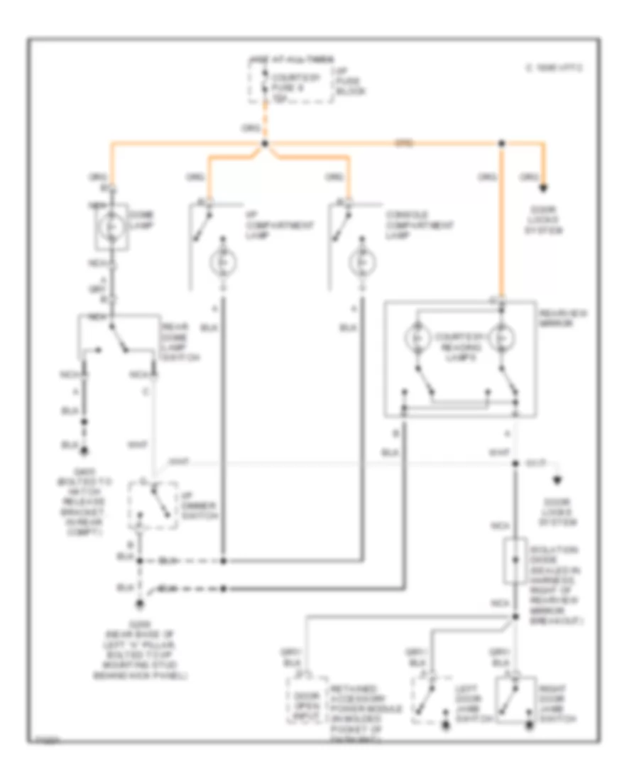
Courtesy Lamp Wiring Diagram, Coupe for Chevrolet Camaro 1995
List of elements for Courtesy Lamp Wiring Diagram, Coupe for Chevrolet Camaro 1995:
- C 1995 vftc
- Console compartment lamp
- Courtesy fuse 8 15a
- Courtesy/ reading lamps
- Dome lamp
- Door locks system
- Door open input
- G200 (near base of left "a" pillar, bolted to i/p mounting stud behind kick panel)
- G405 (bolted to hatch release bracket, in rear compt)
- Hot at all times
- I/p compartment lamp
- I/p dimmer switch
- I/p fuse block
- Isolation diode (sealed in harness, right of rearview mirror breakout)
- Left door jamb switch
- Nca
- Rear dome lamp switch
- Rearview mirror
- Retained accessory power module (in molded pocket of dash mat)
- Right door jamb switch
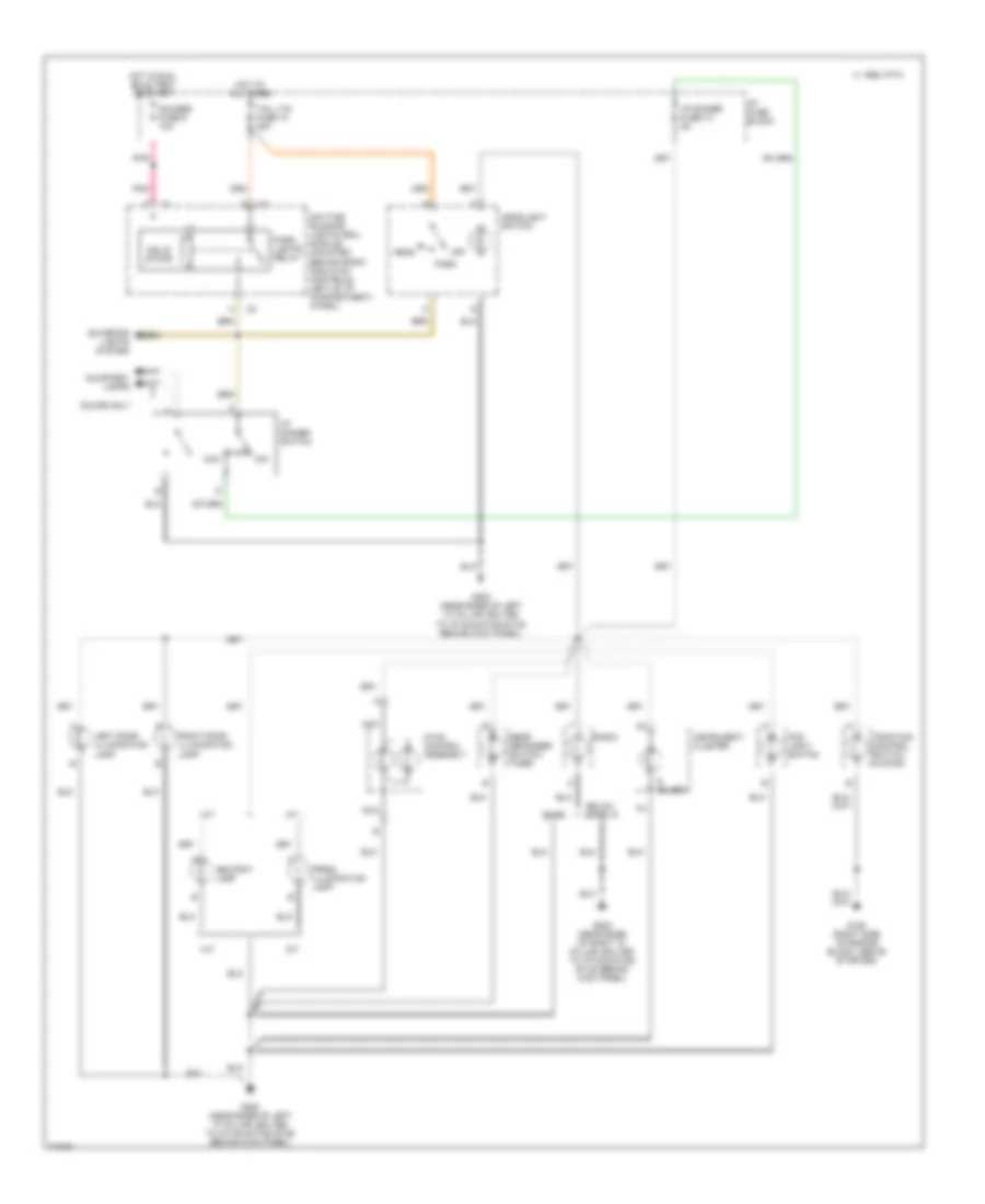
Instrument Illumination Wiring Diagram for Chevrolet Camaro 1995
List of elements for Instrument Illumination Wiring Diagram for Chevrolet Camaro 1995:
- courtesy lamps
- 1995 vftc c
- A/t
- Ashtray lamp
- Base
- Bulbs
- Coupe only
- Daytime running lights (drl) module (mounted behind radio and hvac controls, left of i/p compartment) (w/drl)
- Delco- bose
- Exterior lights system
- Fog light switch
- G120 (right side of engine block, above starter)
- G200 (near base of left "a" pillar, bolted to i/p mounting stud behind kick panel)
- G203 (near base of right "a" pillar, bolted to i/p mounting stud behind kick panel)
- Gauges fuse 9 10a
- Head
- Headlight switch
- Hot at all times
- Hot in run, bulb test or start
- Hvac control assembly
- I/p dimmer fuse 13 5a
- I/p dimmer switch
- I/p fuse block
- Instrument cluster
- Left door illumination lamp
- M/t
- Max
- Min
- Nca
- Off
- Park
- Park lights relay
- Pnk
- Prndl illumination lamp
- Radio
- Rear defogger switch/ timer
- Right door illumination lamp
- Solid state
- Tail lts fuse 10 20a
- Traction control switch (w/nw9)
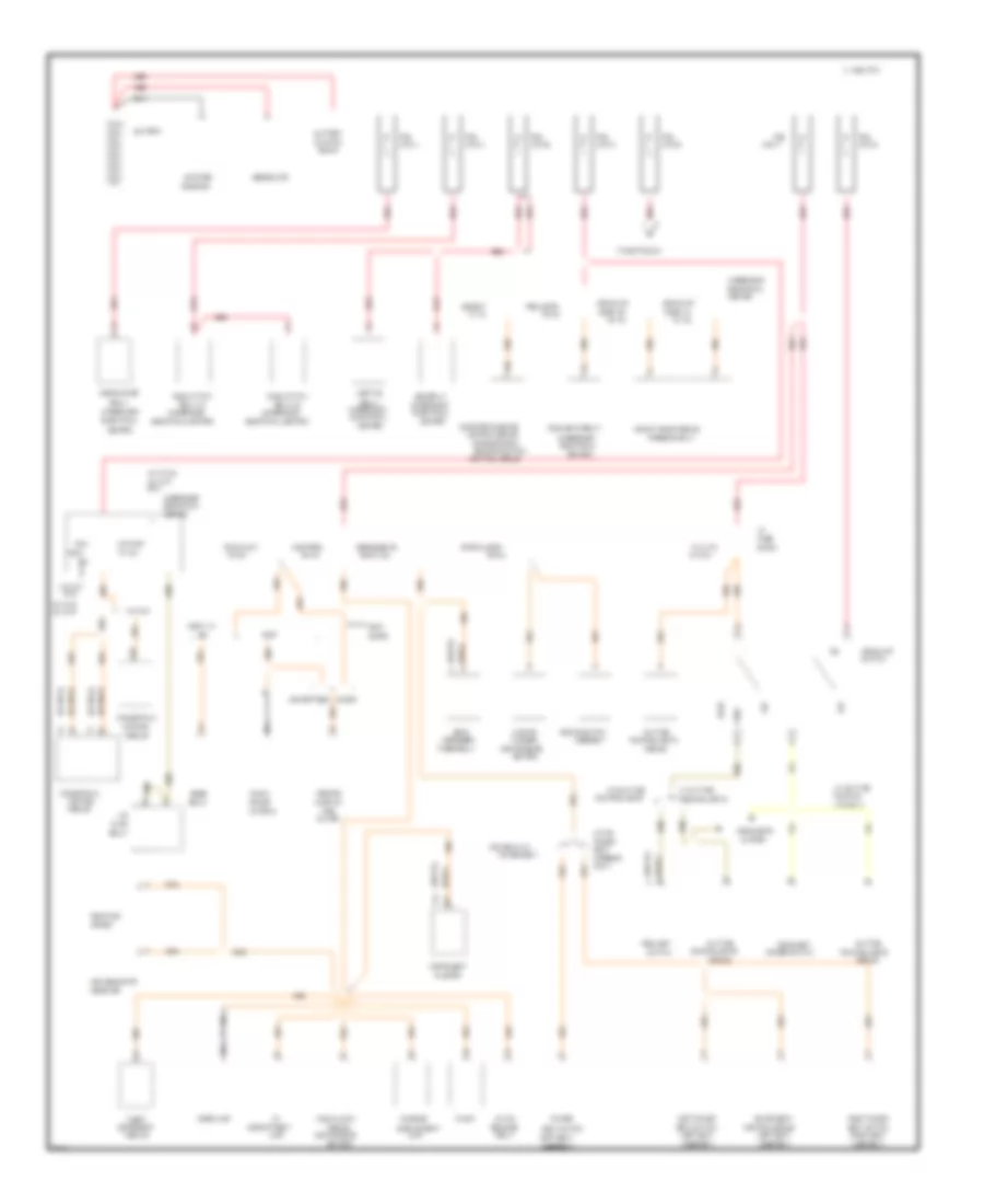
POWER DISTRIBUTION
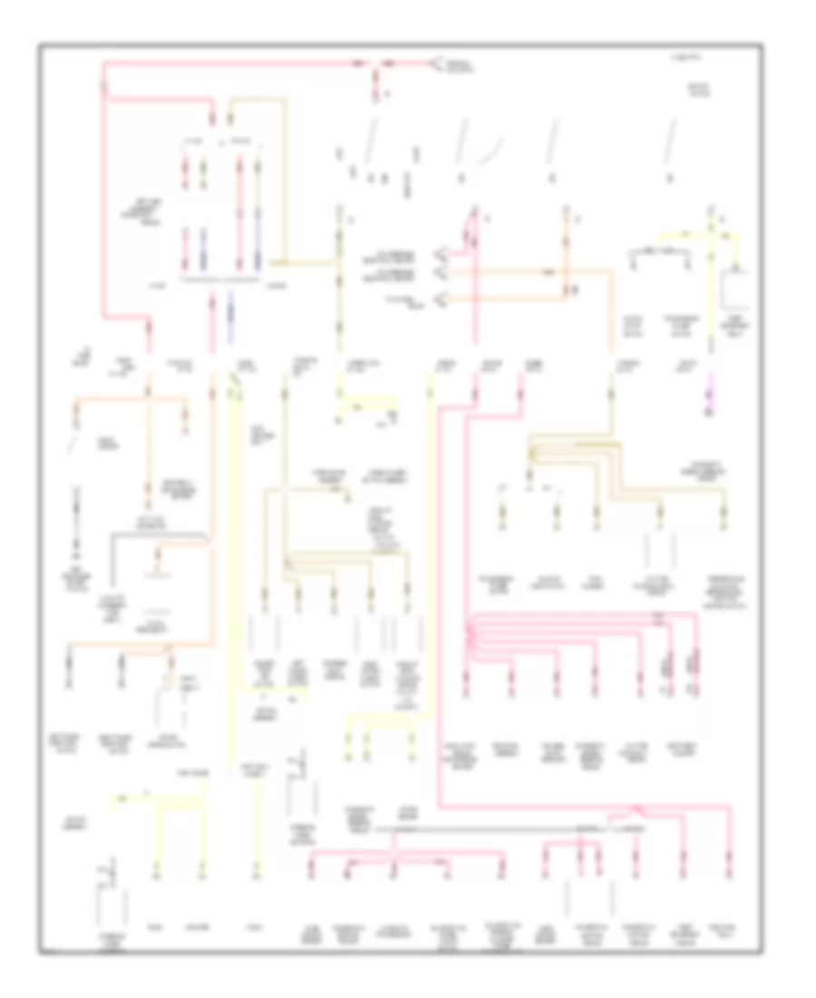
Power Distribution Wiring Diagram (1 of 3) for Chevrolet Camaro 1995
List of elements for Power Distribution Wiring Diagram (1 of 3) for Chevrolet Camaro 1995:
- # 7 20a
- #1 5a
- #10 20a
- #2 20a
- #3 15a
- #4 15a
- #4 25a
- #6 20a
- #8 15a
- #8 5a
- (chevy)
- (convenience
- (firebird
- (firebird only)
- (left seat
- (pont)
- (right seat
- (underhood
- (v6 vin s)
- (v8 vin p)
- (w/ daytime
- 10a
- A13
- A20
- Abs bat
- Abs relay
- Air
- Air pump
- Antenna
- Asr/tcs
- Assembly
- Assembly)
- Audio alarm
- B10
- Battery
- Block
- Bose
- Brake switch
- Brake/traction
- C 1995 vftc
- C14
- Cb #12 30a
- Center
- Center)
- Chevy w/
- Cluster
- Compact
- Compartment
- Console
- Control
- Control module
- Convertible
- Coolant fan
- Coupe
- Courtesy
- Daytime
- Defog/seats
- Defogger
- Deterrent
- Dimmer switch
- Disk
- Dome lamp
- Door, lh
- Door, rh
- Driver 6-way
- Electrical
- Electrical center)
- Electronic brake
- Flasher
- Fog light
- Fog lights
- Fog lights relay
- Fus
- Fuse
- Generator
- Hatch
- Hazard
- Head
- Headlamp
- Headlight
- Headlights
- Headlt door module
- High blower
- I/p
- Instrument
- Junction
- Keyless entry
- Lamp
- Left power
- Link a
- Link b
- Link c
- Link e
- Link f
- Link k
- Link z
- Lts only)
- Mirror
- Module
- Nca
- Off
- Only)
- Or electronic
- Park
- Pcm
- Player
- Pont
- Power
- Power seat
- Powertrain
- Pump
- Radio
- Radio accy
- Rear
- Rearview
- Receiver
- Red
- Relay
- Relay
- Relay #1
- Relay #2
- Release
- Remote
- Right power
- Running
- Running lights
- Seat
- Seat switch
- Solenoid
- Starter
- Stop/hazard
- Switch
- System
- Tail lts
- Theft
- Timer/relay
- To ignition sw
- U65
- Ultima
- Underhood
- V6 vin k
- V6 vin k only
- V6 vin s &
- V6 vin s v8 vin p
- V8 vin p only
- W/ daytime
- W/o daytime
Power Distribution Wiring Diagram (2 of 3) for Chevrolet Camaro 1995
List of elements for Power Distribution Wiring Diagram (2 of 3) for Chevrolet Camaro 1995:
- v6 vin s
- #1 15a
- #11 25a
- #14 25a
- #16 3a
- #17 15a
- #2 15a
- #5 15a
- #7 15a
- #9 10a
- & chevy
- (chev)
- (chevy)
- (con-
- (convenience
- (near base
- (pont)
- (pontiac)
- (v8 vin p
- 30a
- A pillar)
- A/t
- A10
- A19
- A31 only)
- Accessory
- Accy
- Airbag
- Airflow
- Amplifier
- Arming
- Assembly
- Au3 only)
- Audio alarm
- Automatic
- Auxiliary
- B10
- Back-up
- Block
- Brake sw
- Bulb test
- C 1995 vftc
- Canister
- Cb #15
- Center)
- Cigar
- Cigar/
- Cluster
- Clutch
- Connector
- Control
- Control switch
- Controls
- Conver-
- Coolant
- Crank
- D13
- Data link
- Daytime
- Deterrent
- Diagnostic
- Door lock
- Down
- Electrical center
- Emission
- Energy
- Energy reserve
- Entry
- Evaporative
- Express
- Flasher
- Fuel pump
- Fus link e
- Fuse
- G200
- Gages
- Hatch
- Horn
- Horn relay
- I/p
- Ignition
- Instrument
- Keyless
- Latching
- Left
- Left power
- Level
- Light switch
- Lighter
- Lock
- M/t
- M/t a/t
- Mass
- Mirror switch
- Module
- Nca
- Of left
- Off
- Only)
- Pcm ign
- Performance
- Performance/
- Pnk
- Pont conv
- Pont coupe
- Power
- Power (rap)
- Powertrain
- Purge
- Pwr accy
- Radio
- Range
- Receiver
- Red
- Relay
- Release sw
- Reserve
- Retained
- Right
- Right power
- Run
- Running lights
- Running lt
- Sensor
- Sir coil
- Solenoid valve
- Start
- Steering
- Switch
- Switch assembly
- Switch or
- Theft
- Tible
- To i/p fuse
- To underhood
- Top
- Traction
- Transmission
- Turn
- Turn b-u
- V6 vin k
- V8 vin p
- Vacuum
- Vertible
- W/ au3
- W/ rap
- W/o
- W/o au3
- W/o au3 &
- W/o rap
- Wheel
- Window
- Windows
- Wiper motor
- Wiper/wash
- Wiper/washer
- Wire
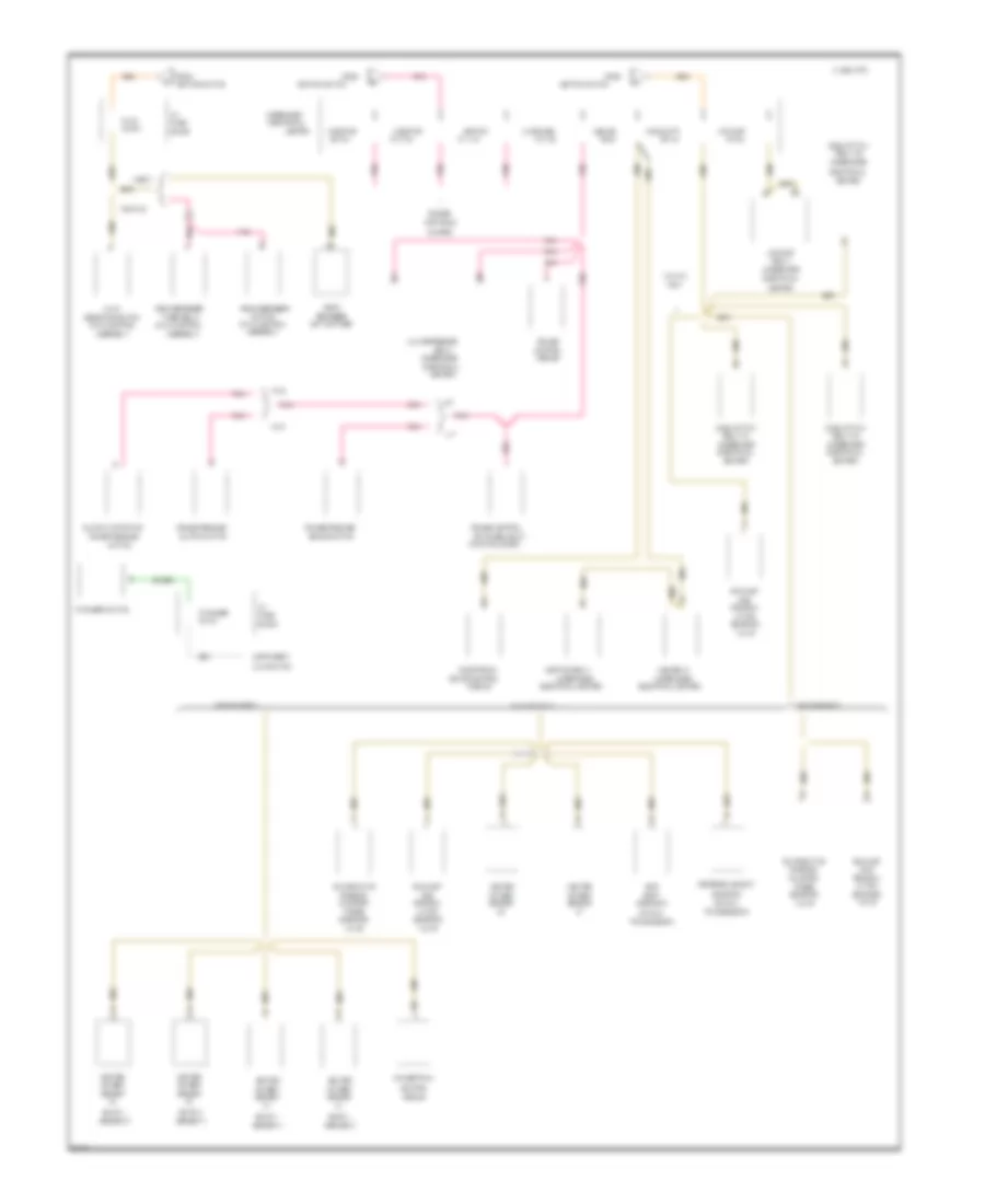
Power Distribution Wiring Diagram (3 of 3) for Chevrolet Camaro 1995
List of elements for Power Distribution Wiring Diagram (3 of 3) for Chevrolet Camaro 1995:
- #10 7.5a
- #11 10a
- #12 15a
- #13 5a
- #3 25a
- #5 5a
- #6 10a
- #7 20a
- #9 7.5a
- (bank 1,
- (bank 2,
- (hvac control
- (manual
- (underhood
- (v6 vin k only)
- (v6 vin s only)
- (v8 vin p only)
- A/c compressor
- A/c-cruise
- A/t
- A68
- Abs ign
- Abs relay
- Air pump
- Asr/tcs relay
- Assembly)
- B11
- Block
- Brake control
- Brake switch
- C 1995 vftc
- Canister
- Center
- Center)
- Chevy
- Clutch anticipate
- Clutch switch
- Control
- Controls
- Coolant fan
- Cruise
- Cruise control
- Cruise release
- Cruise release/
- Defogger
- Electrical
- Electrical center)
- Electronic
- Emission
- Engine
- Evaporative
- Exhaust
- Fans/actr
- From
- Function lever)
- Fuse
- Gas
- Heated
- Hvac
- I/p
- I/p dimmer
- I/p dimmer switch
- Ignition
- Ignition switch
- Illumination
- Injector
- Instrument
- Lation
- M/t
- Module
- Only
- Oxygen
- Pnk
- Pontiac
- Powertrain
- Purge
- Rear
- Rear defogger
- Recircu-
- Relay
- Relay #1
- Relay #2
- Relay #3
- Reverse lockout
- Selector switch
- Sensor
- Sensor 1)
- Sensor 2)
- Sensor 3)
- Shift
- Skip
- Solenoid
- Switch
- Switch/timer
- Switches (multi-
- System
- Timer/relay
- Transmission)
- Underhood
- V6 vin k
- Valve
- Vin p
- Vin s
POWER DOOR LOCKS
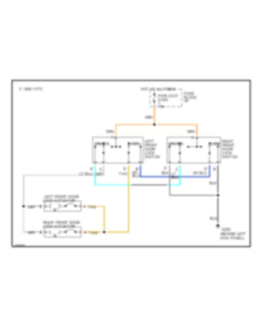
Door Lock Wiring Diagram for Chevrolet Camaro 1995
List of elements for Door Lock Wiring Diagram for Chevrolet Camaro 1995:
- C 1995 vftc
- Fuse block: i/p
- G200 (behind left kick panel)
- Hot at all times
- Left front door lock actuator
- Left front door lock switch
- Lock
- Orn
- Pwr accy fuse 15a
- Right front door lock actuator
- Right front door lock switch
- Tan
- Unlock
Keyless Entry Wiring Diagram for Chevrolet Camaro 1995
List of elements for Keyless Entry Wiring Diagram for Chevrolet Camaro 1995:
- 10a
- 15a
- A/t
- Brake warning system
- C 1995 vftc
- Courtesy fuse 8
- Data link connector (below left side of i/p)
- Drl module (behind left of i/p)
- G120 (right side of engine)
- G200 (near base of left "a" pillar, bolted to i/p mounting stud behind kick panel)
- G407 (center rear of luggage compt)
- Gages fuse 9
- Ground
- Hatch release
- Hatch release actuator
- Hatch release relay (right side of sir bracket, behind i/p)
- Hatch release switch
- Hot at all times
- Hot in accy or run or during
- Hot in run, bulb test or start
- I/p fuse block
- Ignition
- Interior lights system
- Interior lts ground
- Keyless entry receiver (behind right side of i/p, behind kick panel)
- Left front door isolation relay
- Left front door lock actuator
- Left power door lock switch
- Lock
- M/t
- Park brake input
- Park brake switch
- Park/ neutral position switch (under console)
- Pnk
- Program input
- Pwr accy fuse 7
- Retained accessory power
- Right front door lock actuator
- Right power door lock switch
- Tan
- Unlock
- Unlock input/output
- W/ drl
- W/o drl
POWER MIRRORS
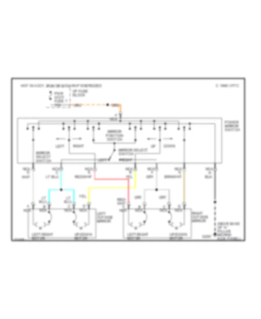
Power Mirror Wiring Diagram for Chevrolet Camaro 1995
List of elements for Power Mirror Wiring Diagram for Chevrolet Camaro 1995:
-
- (near base of "a" pillar behind kick panel)
- A nca
- B nca
- C 1995 vftc
- C nca
- D nca
- Down
- G200
- Hot in accy, run or with rap energized
- I/p fuse block
- Left
- Left outside mirror
- Left/right motor
- Mirror position switch
- Mirror select switch
- Nca
- Nca b
- Nca d
- Nca e
- Nca g
- Power mirror switch
- Pwr accy fuse 7 15a
- Right
- Right outside mirror
- Up/down motor
POWER SEATS
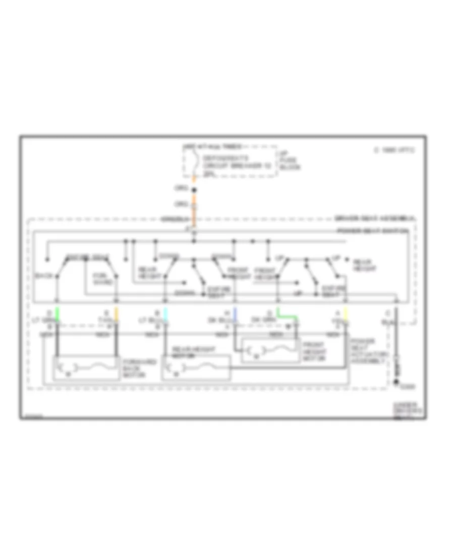
6-Way Power Seat Wiring Diagram for Chevrolet Camaro 1995
List of elements for 6-Way Power Seat Wiring Diagram for Chevrolet Camaro 1995:
- g300
- (under driver's seat)
- Back
- C 1995 vftc
- Defog/seats circuit breaker 12 30a
- Down
- Driver seat assembly
- E tan a
- Entire seat
- For- ward
- Forward/ back motor
- Front height
- Front height motor
- Hot at all times
- I/p fuse block
- Nca
- Power seat actuator assembly
- Power seat switch
- Rear height
- Rear height motor
Lumbar Wiring Diagram for Chevrolet Camaro 1995
List of elements for Lumbar Wiring Diagram for Chevrolet Camaro 1995:
- Air in/out
- C 1995 vftc
- Cutout relay
- Deflate
- Deflate relay
- Defog/seats circuit breaker 12 30a
- Driver power seat switch
- Driver seat assembly
- G300 (under drivers seat)
- Hot at all times
- I/p fuse block
- Inflate
- Inflate relay
- Lateral
- Lateral bladder
- Lumbar
- Lumbar bladder
- Passenger power seat switch
- Passenger seat assembly
- Power seat control module
- Pressure switch
- Pump assembly
- Solenoid valve assembly
POWER TOP/SUNROOF
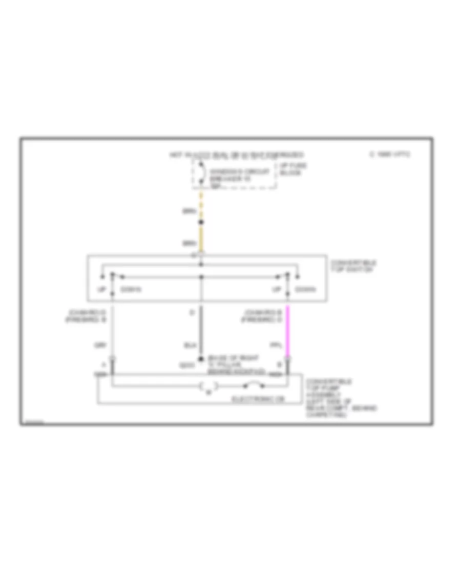
Convertible Top Wiring Diagram for Chevrolet Camaro 1995
List of elements for Convertible Top Wiring Diagram for Chevrolet Camaro 1995:
- (base of right "a" pillar, behind kickpad)
- (camaro) b d
- (camaro) d b
- (firebird)
- C 1995 vftc
- Convertible top pump assembly (left side of rear compt, behind carpeting)
- Convertible top switch
- Down
- Electronic cb
- G203
- Hot in accy,run, or w/ rap energized
- I/p fuse block
- Nca
- Windows circuit breaker 15 30a
POWER WINDOWS
Power Window Wiring Diagram for Chevrolet Camaro 1995
List of elements for Power Window Wiring Diagram for Chevrolet Camaro 1995:
- (near base of left "a" pillar, behind kick panel)
- G200
- Hot in accy, run or with rap energized
- I/p fuse block
- Left power window switch
- Left window motor
- Left window switch
- Power window control module (center of dash mat, above floor tunnel)
- Right power window switch
- Right window motor
- Right window switch
- Solid state
- Tan
- Windows circuit breaker 15 30a
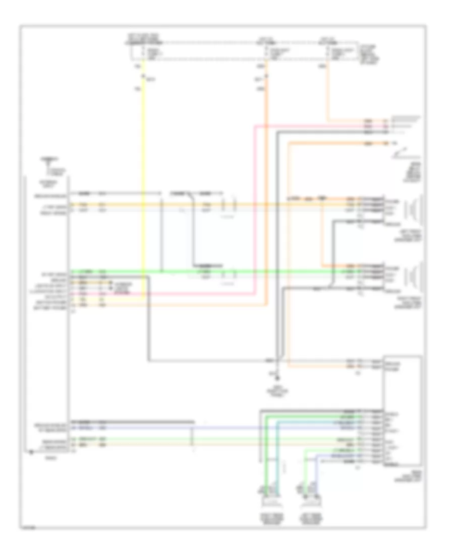
RADIO
Radio Wiring Diagrams, with Bose System for Chevrolet Camaro 1995
List of elements for Radio Wiring Diagrams, with Bose System for Chevrolet Camaro 1995:
- front spkrs
- Antenna
- Antenna input
- Aud +
- Aud -
- Bare
- Battery power
- Bose relay (below center a/c duct)
- Coaxial cable
- G203 (right kick panel)
- Ground
- Ground shields
- Hot at all times
- Hot in acc, run or w/ retained accessory power
- I/p fuse block (behind left side of dash)
- Ignition power
- Illumination input
- Interior lights system
- L aud +
- Left front amplifier/ speaker unit
- Left rear subwoofer speaker
- Lights on input
- Lr +
- Lr -
- Lt frt spkr
- Lt rear spkr
- Nca
- On output
- Pnk
- Power
- Pwr accy fuse 7 15a
- R aud +
- Radio
- Radio accy fuse 4 25a
- Radio fuse 17 15a
- Rear amplifier/ speaker unit
- Rear spkrs
- Right front amplifier/ speaker unit
- Right rear subwoofer speaker
- Rr +
- Rr -
- Rt frt spkr
- Rt rear spkr
- S211
- S218
- S221
- S258
- S264
- Shield
- Tan
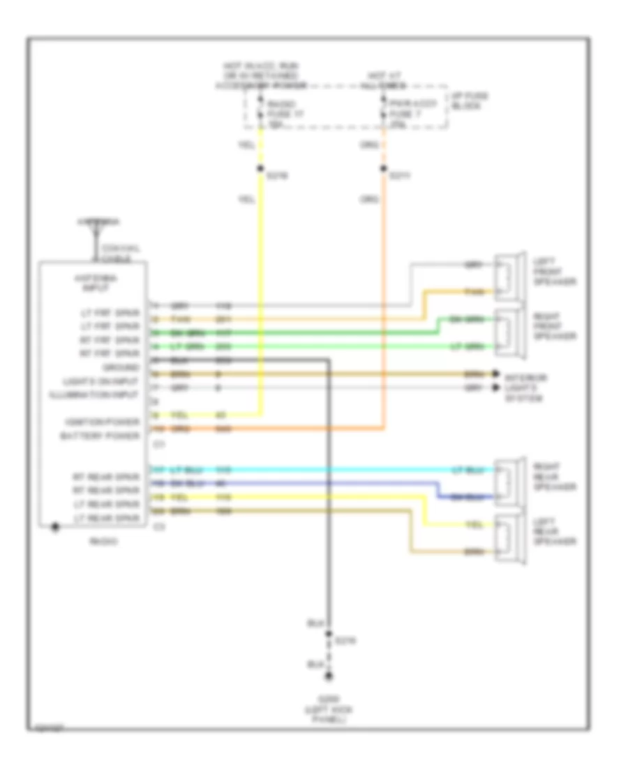
Radio Wiring Diagrams, without Bose System for Chevrolet Camaro 1995
List of elements for Radio Wiring Diagrams, without Bose System for Chevrolet Camaro 1995:
- All times
- Antenna
- Antenna input
- Battery power
- Coaxial cable
- G200 (left kick panel)
- Ground
- Hot at
- Hot in acc, run or w/ retained accessory power
- I/p fuse block
- Ignition power
- Illumination input
- Interior lights system
- Left front speaker
- Left rear speaker
- Lights on input
- Lt frt spkr
- Lt rear spkr
- Pwr accy fuse 7 15a
- Radio
- Radio fuse 17 15a
- Right front speaker
- Right rear speaker
- Rt frt spkr
- Rt rear spkr
- S211
- S216
- S218
- Tan
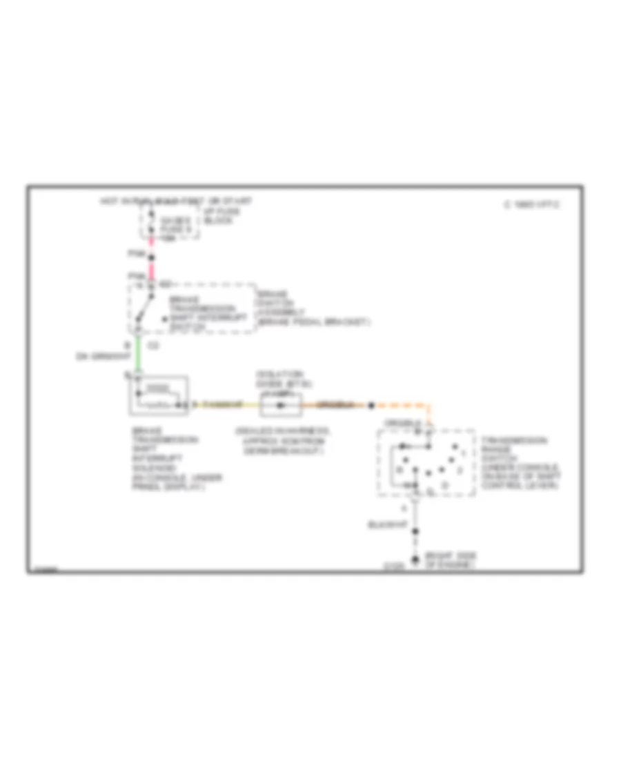
SHIFT INTERLOCKS
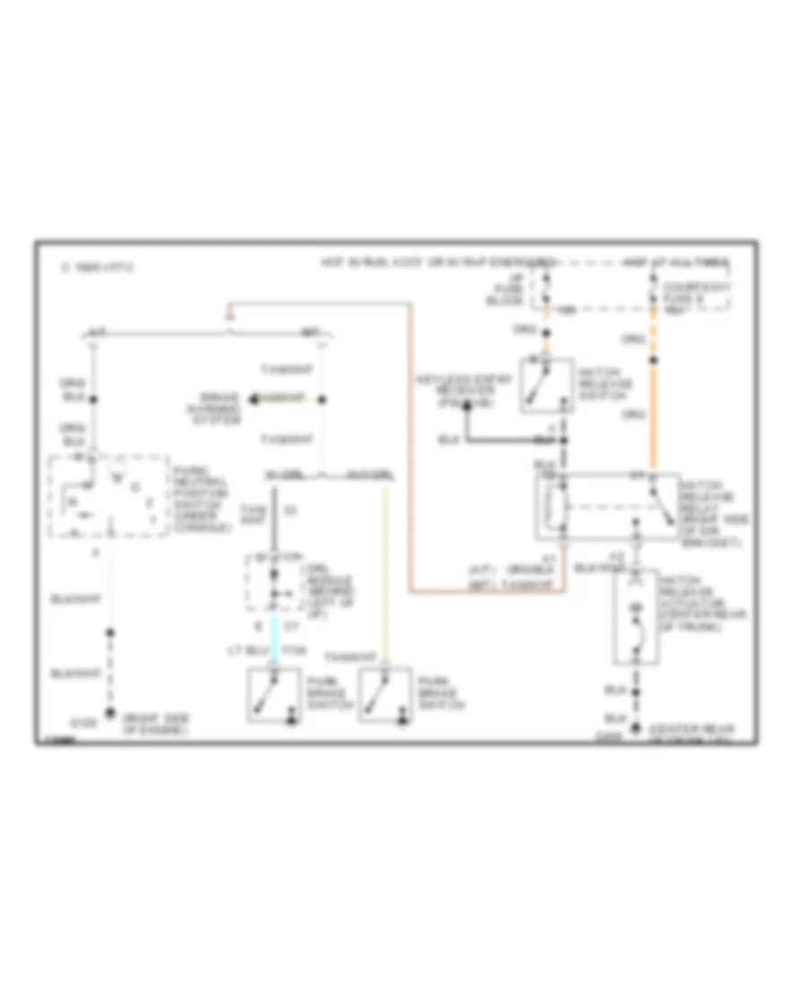
Shift Interlock Wiring Diagram for Chevrolet Camaro 1995
List of elements for Shift Interlock Wiring Diagram for Chevrolet Camaro 1995:
- (1 amp)
- (right side of engine)
- (sealed in harness, approx 6cm from derm breakout)
- Brake switch assembly (brake pedal bracket)
- Brake transmission shift interrupt solenoid (in console, under prndl display)
- Brake transmission shift interrupt switch
- C 1995 vftc
- G120
- Gages fuse 9 10a
- Hot in run, bulb test or start
- I/p fuse block
- Isolation diode (btsi)
- Pnk
- Pnk a
- Transmission range switch (under console, on base of shift control lever)
STARTING/CHARGING
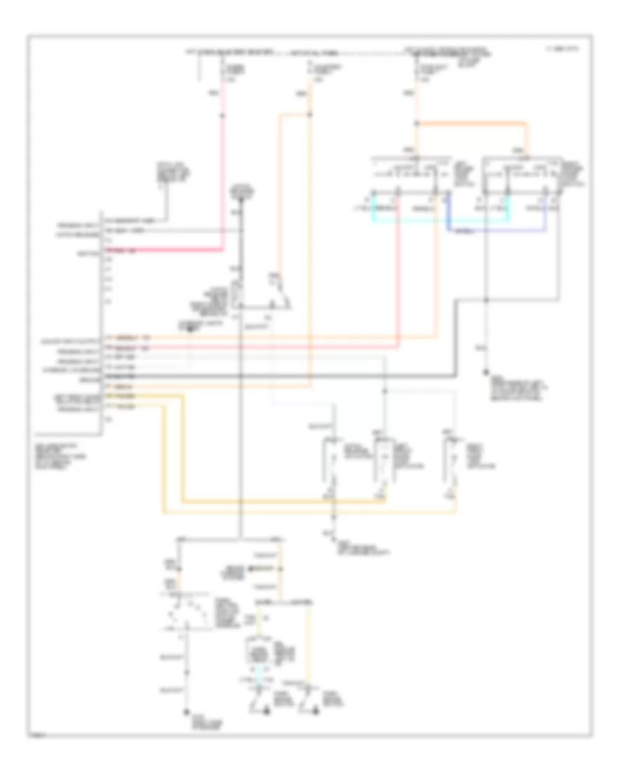
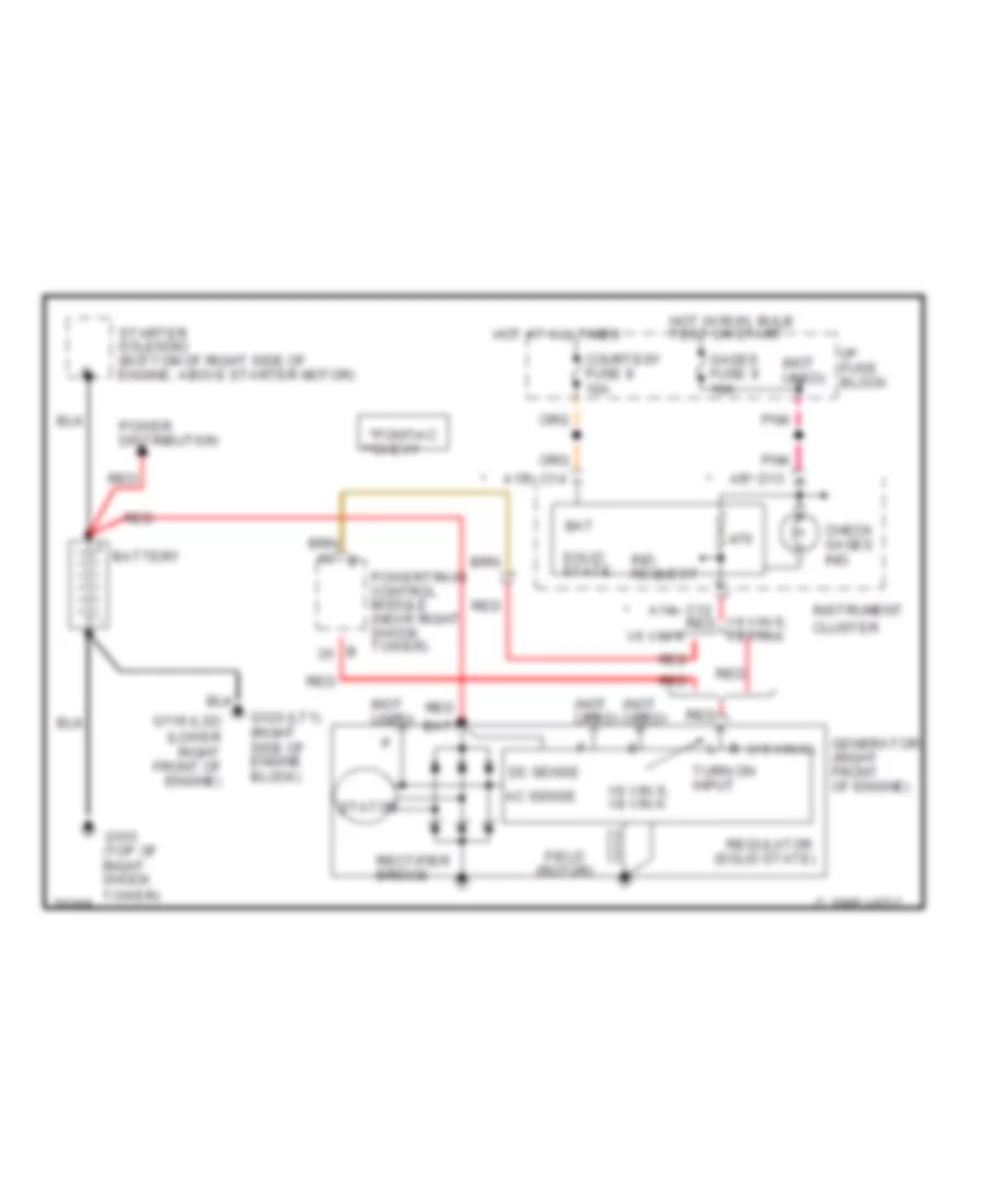
Charging Wiring Diagram for Chevrolet Camaro 1995
List of elements for Charging Wiring Diagram for Chevrolet Camaro 1995:
- a13, c14
- a14, c12 red v8 vin k
- a5, d13
- (not used)
- (solid state)
- (v6 vin k)
- *pontiac **chevy
- Ac sense
- Bat
- Batt
- Battery
- C 1995 vftc
- Check gages ind.
- Courtesy fuse 8 10a
- Dc sense
- Field (rotor)
- G103 (top of right shock tower)
- G119 (l32) (lower right front of engine)
- G120 (lt1) (right side of engine block)
- Gages fuse 9 10a
- Generator (right front of engine)
- Hot at all times
- Hot in run, bulb test or start
- I/p fuse block
- Ind. request
- Instrument cluster
- Pnk
- Power distribution
- Powertrain control module (near right shock tower) b
- Rectifier bridge
- Red
- Regulator
- Solid state
- Starter solenoid (bottom of right side of engine, above starter motor)
- Stator
- Turn on input
- V6 vin k
- V6 vin s,
- V6 vin s, v8 vin k
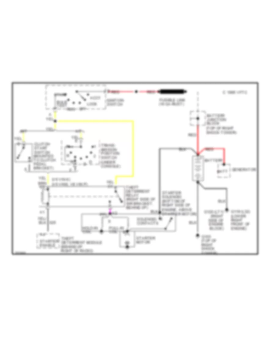
Starting Wiring Diagram for Chevrolet Camaro 1995
List of elements for Starting Wiring Diagram for Chevrolet Camaro 1995:
- (top of right shock tower)
- (v6 vin k)
- (v6 vins, v8 vin p)
- A/t
- Accy
- Battery
- Battery junction block
- Bulb test
- C 1995 vftc
- Clutch start switch (mounted to clutch pedal bracket)
- Fusible link (16 ga-rust)
- G103 (top of right shock tower)
- G119 (l32) (lower right front of engine)
- G120 (lt1) (right side of engine block)
- Generator batt
- Hold-in coil
- Ignition switch
- Lock
- M/t
- Off
- Pull-in coil
- Red
- Run
- Solenoid contacts
- Start
- Starter enable
- Starter motor
- Theft deterrent module (behind i/p, right of radio)
- Theft deterrent relay (right side of sir bracket, behind i/p)
- Trans- mission position switch (under console)
SUPPLEMENTAL RESTRAINTS
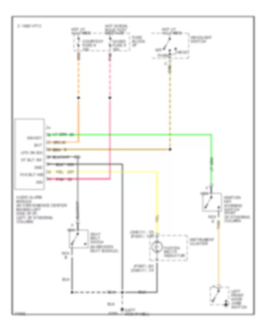
Supplemental Restraint Wiring Diagram for Chevrolet Camaro 1995
List of elements for Supplemental Restraint Wiring Diagram for Chevrolet Camaro 1995:
- (chevrolet) (pontiac)
- (not used)
- (pontiac) (chevrolet)
- 10.2k
- 2.49k
- 8.45k
- A10
- A11
- A12
- A7 c16
- Air bag fuse 1 15a
- Air bag ind
- Audio alarm module
- B10
- B11
- B12
- C 1995 vftc
- Computer data lines
- Convenience center (left of steering column, bottom of i/p carrier)
- Crank fuse 16 3a
- Crank input
- D13 a5
- Diagnostic energy reserve module (derm) (behind right side of i/p compt)
- Driver 36v lr
- Driver inflator module (mounted on steering wheel)
- Driver side "high"
- Driver side "low"
- Driver source sense
- Dual pole arming sensor (floor tunnel bracket, under console)
- Forward discriminating sensor (center of front end tie bar, near hood latch)
- G103 (top of right shock tower)
- G200 (near base of left "a" pillar, bolted to i/p mounting stud behind kick panel)
- Gages fuse 9 15a
- Ground
- Hot in run, bulb test or start
- Hot in start
- I/p fuse block
- Ign 1
- Instrument cluster
- Nca
- Pass 36v lr
- Pass side "high"
- Pass side "low"
- Pass source sense
- Passenger compt discriminating sensor (upper dash, right of steering column)
- Passenger inflator module (right side of i/p, above i/p compt)
- Pnk
- Redundant ind ground
- Redundant ind ign 1
- Seat belt input
- Seat belt sw signal
- Seat belt switch (in driver's seat belt buckle)
- Serial data
- Shorting bar
- Sir coil assembly (top of steering column)
- Sir ind
- Tan
TRANSMISSION
3.4L
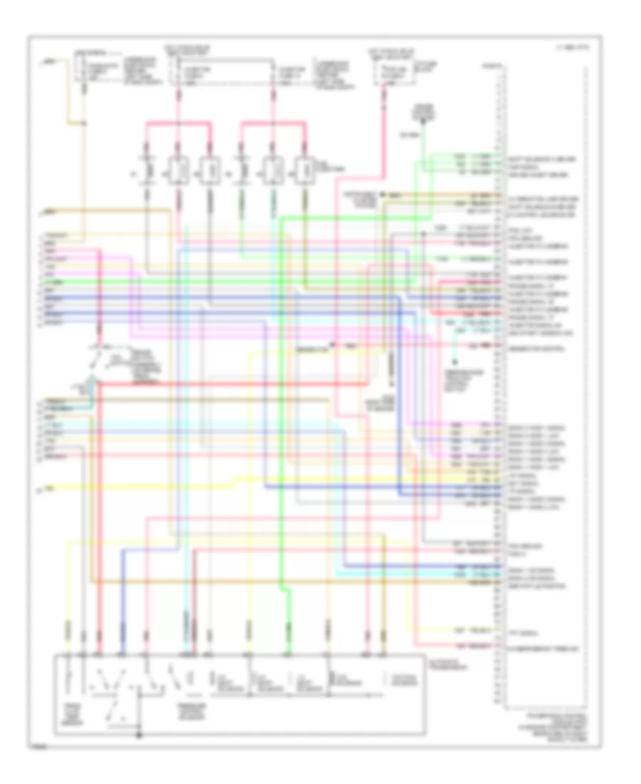
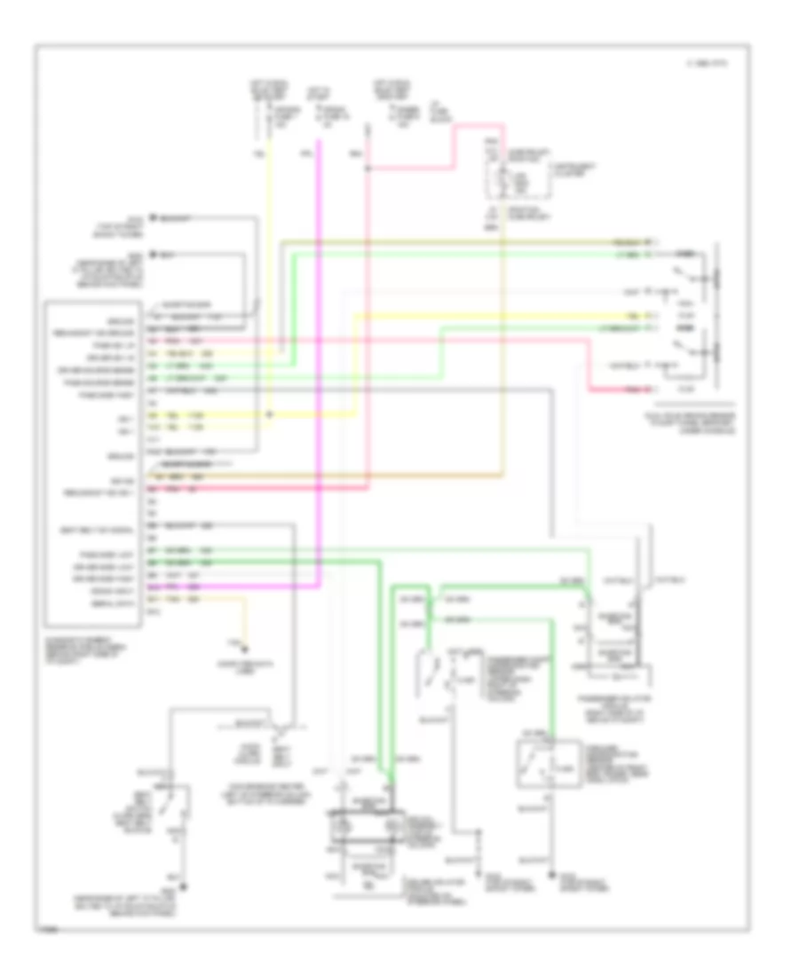
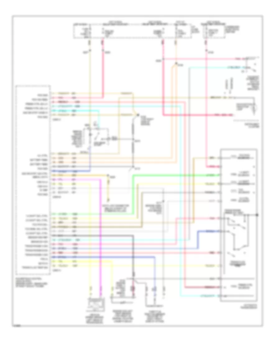
3.4L (VIN S), Transmission Wiring Diagram for Chevrolet Camaro 1995
List of elements for 3.4L (VIN S), Transmission Wiring Diagram for Chevrolet Camaro 1995:
- (below & right of steering column)
- (chevy)
- (pontiac)
- 1-2 shift
- 1-2 shift sol ctrl
- 2-3 shift sol ctrl
- 2-3 shift solenoid
- 2nd gear start
- 2nd gr strt ind ctrl
- 2nd gr strt mode in
- 3-2 ctrl solenoid
- 3-2 shift sol ctrl
- 5v ref
- Automatic transmission
- Battery feed
- Brake sw sig
- Conn a
- Conn b
- Conn c
- D13
- Data link connector
- Ects in
- Engine coolant temp sensor (top front of engine, mounted under plenum)
- G120 (top right side of engine)
- Gages fuse 9 10a
- Hot at all times
- Hot in run
- Hot in run, bulb test or start
- I/p fuse block
- Ignition fuse 11 10a
- Instrument cluster
- Malfunction indicator lamp
- Mil ctrl
- Pcm fuse 8 10a
- Pcm gnd
- Pcm ign feed
- Pcm ign fuse 5 15a
- Perfor- mance/ traction control switch (pontiac only)
- Pnk
- Powertrain control module (pcm) (engine compt, rearward of right shock tower)
- Press ctrl
- Press ctrl sol-hi
- Press ctrl sol-lo
- Press sw assy
- Red
- S106
- S110
- S117 (engine harn, 5 cm from pcm brake- out)
- S122 (engine harn, 4 cm from map break- out)
- S128
- S205
- S206
- S207
- S215
- S225
- Sensor gnd ref
- Serial data
- Solenoid
- Tan
- Tcc
- Tcc enbl sol ctrl
- Tcc pwm
- Tcc pwm sol
- Tcc/shift interrupt switch (on brake pedal bracket)
- Throttle position sensor (mounted to right front side of intake)
- Tps in
- Trans fluid temp sensor
- Trans fluid temp sig
- Trans range
- Trans range a sig
- Trans range b sig
- Trans range c sig
- Turn b-u fuse 2 20a
- Underhood electrical center
- Vehicle speed sensor (left rear of transmission)
- Vss in-hi
- Vss in-lo
3.8L
3.8L (VIN K), Transmission Wiring Diagram for Chevrolet Camaro 1995
List of elements for 3.8L (VIN K), Transmission Wiring Diagram for Chevrolet Camaro 1995:
- 1-2 ctrl sol
- 1-2 shift sol
- 2-3 ctrl sol
- 2-3 shift sol
- 2nd gear start
- 3-2 ctrl sol
- 3-2 downshift sol
- 5v reference
- Brake/tcc sw in
- Chevy
- Cruise control system
- Cruise engaged sig
- D13
- Data link connector (under left side of dash)
- Dlc class 2 data
- Ect sens in
- Engine coolant temperature sensor (front of lower intake manifold, under throttle body assy)
- Engine data sens grd
- Fans/actr fuse 6 10a
- G125 (front of engine)
- Gauges fuse 9 10a
- Hot at all times
- Hot in run
- Hot in run, bulb test or start
- I/p fuse block
- Illum
- Instrument cluster
- Interior lights system
- Pcm fuse 8 10a
- Pcm ground
- Pcm ign fuse 5 15a
- Pcs hi
- Pcs low
- Pcs sol
- Pnk
- Pontiac
- Power (battery)
- Power (ignition)
- Powertrain control module (right side of engine compt)
- Range sens 'a' in
- Range sens 'b' in
- Range sens 'c' in
- Red
- Rnge 'a'
- Rnge 'b'
- Rnge 'c'
- S107
- S110
- S117 (engine harness, 16 cm from transmission break-out)
- S119 (engine harness, 4 cm from transmission break-out)
- S205
- S206
- S207
- S215
- Second gear start
- Second gear start engaged indicator
- Second gear start switch
- Stoplamp/ tcc switch (under left side of dash)
- Tan
- Tcc enable sol ctrl
- Tcc pwm sol
- Tcc sol
- Tcc solenoid ctrl
- Tft sensor
- Throttle position sensor (throttle body)
- Tp sens in
- Tr pressure switch assy
- Trans temp sens in
- Trans- mission
- Turn b/u fuse 2 15a
- Uart data link
- Underhood electrical center
- Vehicle speed sensor (left rear of transmission)
- Vss in
- Vss return
5.7L
5.7L (VIN P), Transmission Wiring Diagram for Chevrolet Camaro 1995
List of elements for 5.7L (VIN P), Transmission Wiring Diagram for Chevrolet Camaro 1995:
- (chevy)
- (pontiac)
- 1-2 shift
- 1-2 shift sol
- 2-3 shift sol
- 2-3 shift solenoid
- 2nd gear start
- 3-2 ctrl solenoid
- 3-2 downshift sol
- 5v reference
- Automatic transmission
- Battery in
- Brake switch input
- Conn a
- Conn b
- Conn c
- Conn d
- D13
- Data link connector (left side of dash)
- Ect sens input
- Engine coolant temp sensor (front of engine, on water pump)
- Field service request
- G110 (front of left cylinder head)
- G117 (right rear of engine)
- Gages fuse 9 10a
- Hot at all times
- Hot in run
- Hot in run, bulb test or start
- I/p fuse block
- Ignition fuse 11 10a
- Ignition in
- Instrument cluster
- Malfunction indicator lamp
- Mil control
- Park/neutral in
- Pcm fuse 8 10a
- Pcm ground
- Pcm ign fuse 5 15a
- Pcs hi
- Pcs lo
- Perf mode ind ctrl
- Perf mode sw in
- Performance/traction control switch (pontiac)
- Pnk
- Powertrain control module (pcm) (engine compt, rearward of right shock tower)
- Press ctrl
- Press sw assy
- Range signal "a"
- Range signal "b"
- Range signal "c"
- Red
- S106
- S109
- S122 (engine harn, 25 cm from pcm break- out)
- S128
- S132
- S206
- S207
- S215
- S234 (i/p harn, right end of dash)
- S238 (i/p harn, 7 cm from ctr console break-out)
- S270 (forward lamp harn, 4 cm from ecbm break-out)
- Sensor return
- Serial data
- Solenoid
- Tan
- Tcc
- Tcc pwm
- Tcc pwm sol
- Tcc sol
- Tcc/shift interrupt switch (on brake pedal bracket)
- Throttle position sensor (mounted to side of throttle body)
- Tp sens input
- Trans fluid temp sensor
- Trans range
- Trans temp sig in
- Transmission range switch (base of gear selector lever)
- Turn b-u fuse 2 15a
- Underhood electrical center
- Vehicle speed sensor (left rear of transmission)
- Vss hi
- Vss lo
TRUNK, TAILGATE, FUEL DOOR
Hatch Release Wiring Diagram for Chevrolet Camaro 1995
List of elements for Hatch Release Wiring Diagram for Chevrolet Camaro 1995:
- (a/t)
- (center rear of trunk lid)
- (m/t)
- (right side of engine)
- 15a
- A/t
- Brake warning system
- C 1995 vftc
- Courtesy fuse 8 15a
- Drl module (behind left of i/p)
- G120
- G406
- Hatch release actuator (center rear of trunk)
- Hatch release relay (right side of sir bracket)
- Hatch release switch
- Hot at all times
- Hot in run, accy or w/ rap energized
- I/p fuse block
- Keyless entry receiver (pin c1/b)
- M/t
- Park brake switch
- Park/ neutral position switch (under console)
- W/ drl
- W/o drl
WARNING SYSTEMS
Warning System Wiring Diagrams for Chevrolet Camaro 1995
List of elements for Warning System Wiring Diagrams for Chevrolet Camaro 1995:
- (chevy)
- (chevy) (pont)
- (in driver's seat buckle)
- (left kick panel)
- (pont)
- Audio alarm module (in convenience center behind left side of i/p, left of steering column)
- B3 c4
- Bat
- C 1995 vftc
- C6 a12
- Courtesy fuse 8 15a
- Fas blt ind
- Fasten belts indicator
- Fuse block: i/p
- G200
- Gages fuse 9 10a
- Gnd
- Head
- Headlight switch
- Hot at all times
- Hot in run, bulb test or start
- Ign
- Ign key
- Ignition key warning switch (part of steering column)
- Instrument cluster
- Left front door jamb switch
- Lps on sig
- Nca
- Off
- Park
- Pnk
- Seat belt swich
- St blt sw
- Tan
WIPER/WASHER
Wiper/Washer Wiring Diagram for Chevrolet Camaro 1995
List of elements for Wiper/Washer Wiring Diagram for Chevrolet Camaro 1995:
- 24k
- C 1995 vftc
- End of sweep switch
- Fuse block
- G108 (near top left side of radiator, in top 0f t-bar)
- Hot in acc or run
- Low speed relay
- Mist
- Nca
- Nca e
- Nca h
- Off
- Park relay
- Park switch
- Pnk
- Pulse
- Red
- S113
- Washer pump motor (below engine hood latch)
- Washer switch
- Wiper isolation diode (in fwd lts hrn base of steeering column)
- Wiper motor assembly
- Wiper switch
- Wiper/ wash fuse 14 25a
- Wiper/ washer switch assembly

 Čeština
 Dansk
Dansk Deutsch
 Ελληνικά
 English
 English
 Español
 Suomi
Suomi Français
 Français
 עברית
עברית Hrvatski
 Magyar
 Italiano
 日本語
日本語 한국어
한국어 Nederlands
 Polski
 Português
 Português
 Română
 Русский
 Slovenčina
 Slovenščina
 Türkçe
 中文 (中国)