AIR CONDITIONING
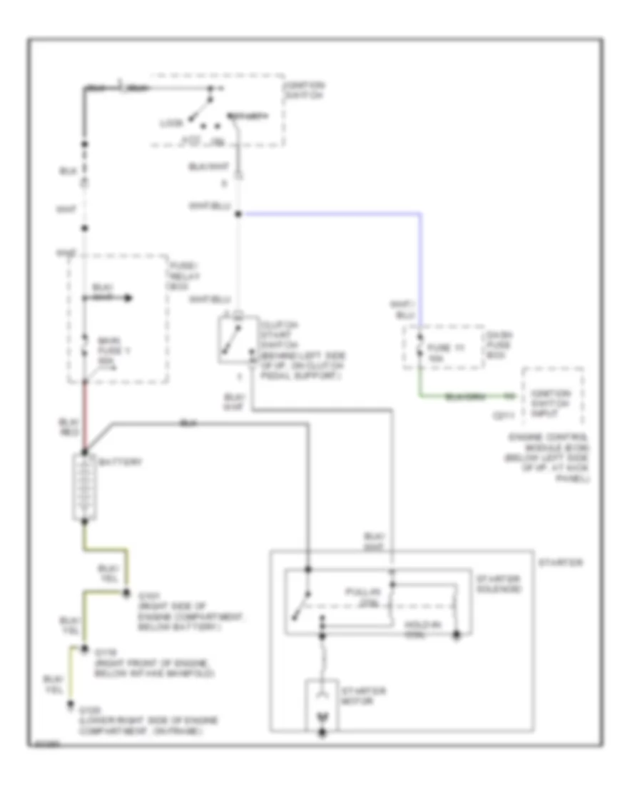
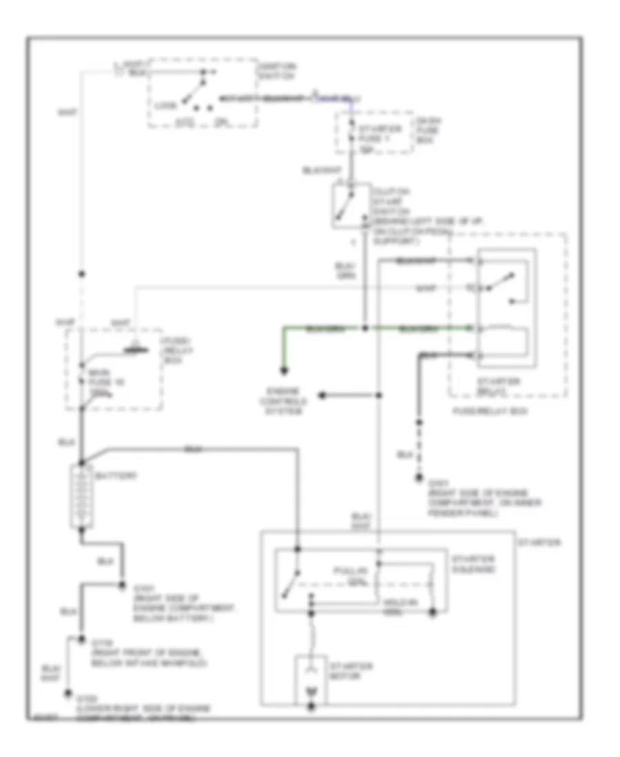
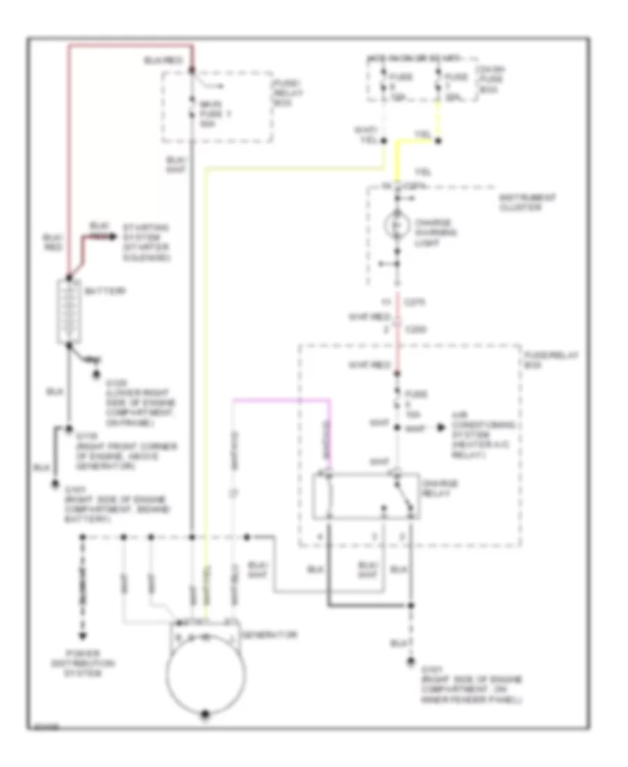
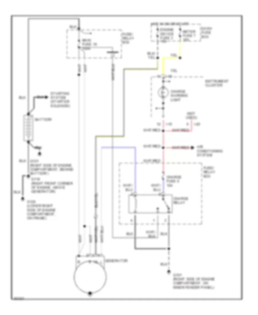
2.6L
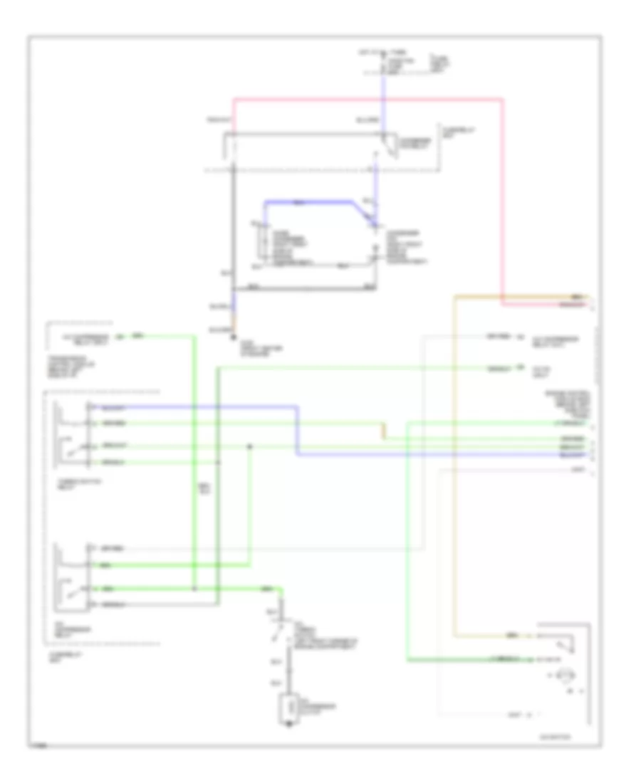
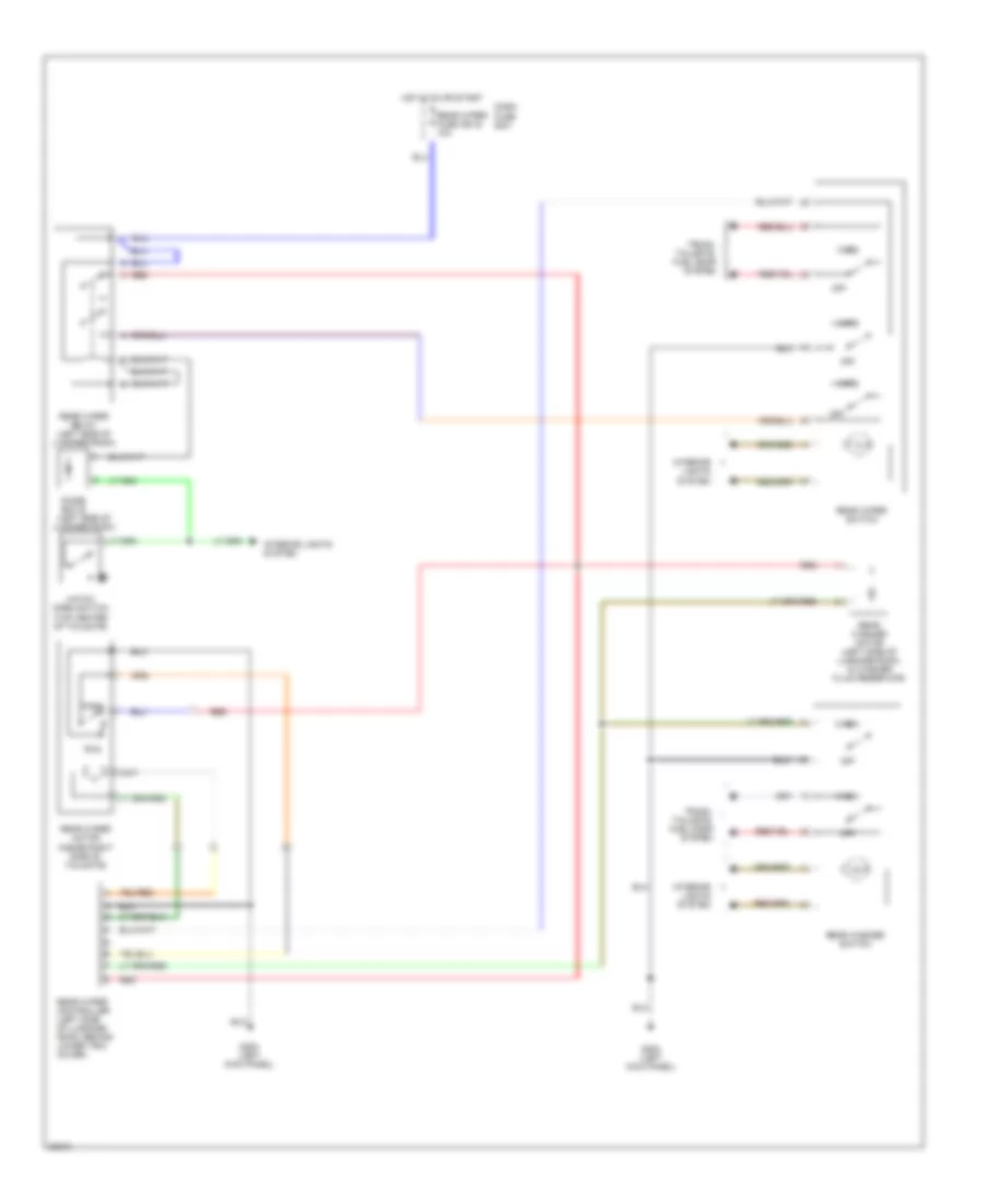
2.6L, A/C Wiring Diagram, Early Production for Isuzu Rodeo S 1995
 https://portal-diagnostov.com/license.html
Automotive Electricians Portal FZCO
Automotive Electricians Portal FZCO
https://portal-diagnostov.com/license.html
https://portal-diagnostov.com/license.html
Automotive Electricians Portal FZCO
Automotive Electricians Portal FZCO
List of elements for 2.6L, A/C Wiring Diagram, Early Production for Isuzu Rodeo S 1995:
- (at left kick panel) g200
- (behind glove box)
- (behind right side of dash) g201
- (left front of vehicle)
- (right side of engine compartment)
- (right side of i/p, above kick panel)
- 10a
- 1995 vftc c
- 20a
- A/c
- A/c on input
- A/c switch
- A/c thermostat relay
- Blower
- Blower switch
- C210
- C289
- C290
- Charge
- Charging system
- Clutch
- Compressor
- Control panel
- Dual
- Electronic thermostat
- Engine control module (behind left kick panel)
- Evaporator temperature sensor
- Fast idle solenoid valve (right side of engine compartment)
- Fuse 7
- Fuse 8
- Fuse/relay box
- G101
- G119 (right front corner of engine)
- Generator
- Heater & a/c
- Heater- a/c
- Hot at all times
- Indicator control
- Main fuse 1 60a
- Motor
- Nca
- Off
- Pressure switch
- Regulator
- Relay
- Resistor block (behind glove box)
- Solid state
- Thermo fuse
- Voltage
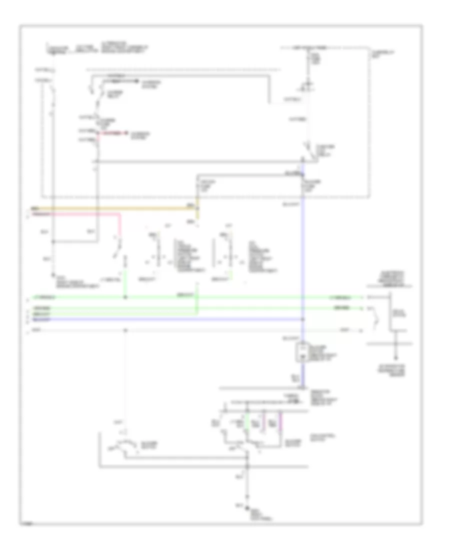
2.6L, A/C Wiring Diagram, Late Production for Isuzu Rodeo S 1995
List of elements for 2.6L, A/C Wiring Diagram, Late Production for Isuzu Rodeo S 1995:
- (behind glove box)
- (left front of vehicle)
- (right kick panel)
- (right side of engine compartment)
- 1995 vftc c
- 20a
- A/c
- A/c on input
- A/c switch
- Air con fuse 10a
- Alternator
- Blower
- Blower fuse
- Blower switch
- C212
- Charge
- Charge fuse 10a
- Charging system
- Clutch
- Compressor
- Dual
- Electronic thermostat
- Engine control module (behind left kick panel)
- Evaporator temperature sensor
- Fan control
- Fast idle solenoid
- Fuse/relay box
- G101
- G119 (right front corner of engine)
- G203
- Heater- a/c
- Hot at all times
- Indicator control
- Main fuse 100a
- Motor
- Nca
- Off
- Pressure switch
- Regulator
- Relay
- Resistor block (behind glove box)
- Solid state
- Switch
- Thermo fuse
- Thermo switch relay
- Valve (right side of engine compartment)
- Voltage
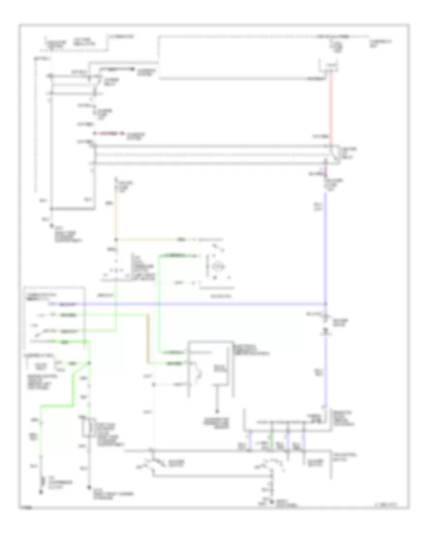
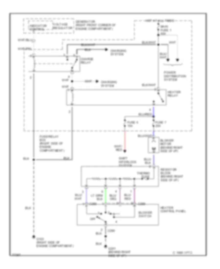
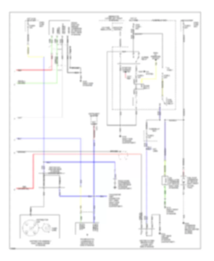
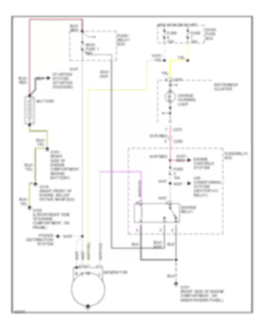
Heater Wiring Diagram, Early Production for Isuzu Rodeo S 1995
List of elements for Heater Wiring Diagram, Early Production for Isuzu Rodeo S 1995:
- 1995 vftc c
- Blower motor (behind right side of i/p)
- Blower switch
- C289
- C290
- Charge relay
- Charging system
- Fuse 6 10a
- Fuse 7 20a
- Fuse/relay box (right side of engine compartment)
- G103 (right side of engine compartment)
- G201 (behind right side of i/p)
- Generator (right front corner of engine compartment)
- Heater control panel
- Heater relay
- Hot at all times
- Indicator control
- Main fuse 1 60a
- Off
- Power distribution system
- Resistor block (behind right side of i/p)
- Shift interlock system
- Thermo fuse
- Voltage regulator
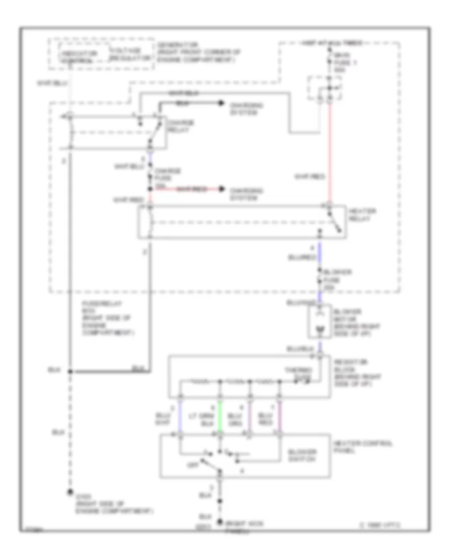
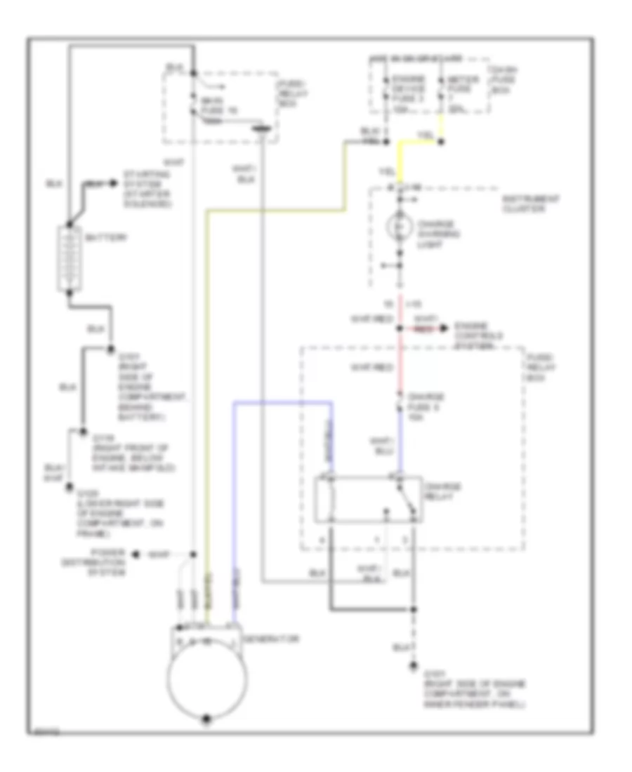
Heater Wiring Diagram, Late Production for Isuzu Rodeo S 1995
List of elements for Heater Wiring Diagram, Late Production for Isuzu Rodeo S 1995:
- (right kick panel)
- 1995 vftc c
- Blower
- Blower motor (behind right side of i/p)
- Blower switch
- Charge fuse 10a
- Charge relay
- Charging system
- Fuse 20a
- Fuse/relay box (right side of engine compartment)
- G103 (right side of engine compartment)
- G203
- Generator (right front corner of engine compartment)
- Heater control panel
- Heater relay
- Hot at all times
- Indicator control
- Main fuse 1 60a
- Off
- Resistor block (behind right side of i/p)
- Thermo fuse
- Voltage regulator
3.2L
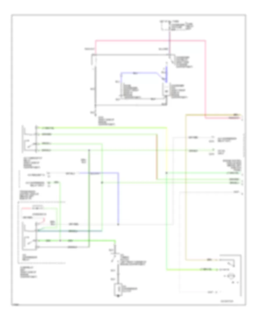
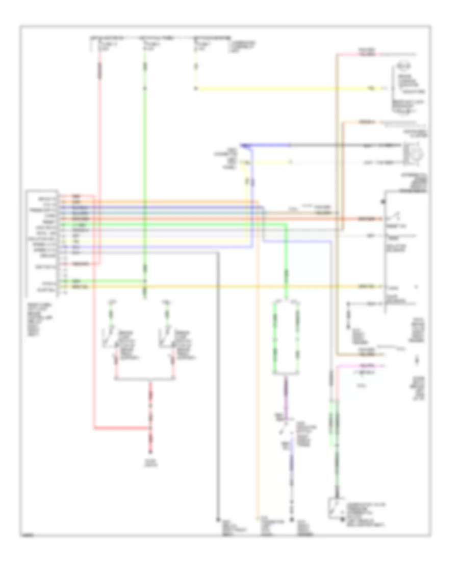
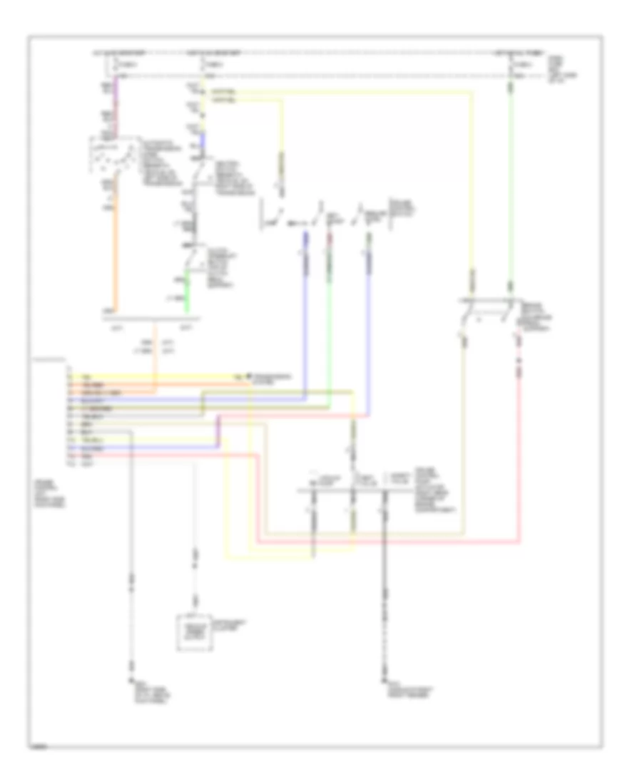
3.2L, A/C Wiring Diagram, Early Production (1 of 2) for Isuzu Rodeo S 1995
List of elements for 3.2L, A/C Wiring Diagram, Early Production (1 of 2) for Isuzu Rodeo S 1995:
- A/c compressor clutch
- A/c compressor relay
- A/c compressor relay cntl
- A/c compressor relay input
- A/c on input
- A/c request in
- A/c switch
- A/c thermo switch (left front corner of engine compartment)
- A/c thermostat relay (right side of engine compartment)
- C218
- C219
- Condenser fan (right front side of engine compartment)
- Condenser fan fuse 30a
- Condenser fan relay (right side of engine compartment)
- Diode box b
- Engine control module (ecm) (behind left side kick panel)
- Fuse/ relay box
- Fuse/relay box (right side of engine compartment)
- G103 (right side of engine compartment)
- Hot at all times
- Noise condenser (right front side of engine compartment)
- Transmission control module (behind left side of i/p)
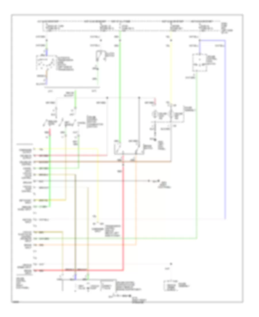
3.2L, A/C Wiring Diagram, Early Production (2 of 2) for Isuzu Rodeo S 1995
List of elements for 3.2L, A/C Wiring Diagram, Early Production (2 of 2) for Isuzu Rodeo S 1995:
- A/c dual pressure switch (left front side of engine compartment)
- A/c triple pressure switch (left front side of engine compartment)
- A/t
- Blower motor (behind right side of i/p)
- Blower switch
- C289
- C290
- Charge relay
- Charging system
- Electronic thermostat (behind right side of i/p)
- Evaporator temperature sensor
- Fuse 6 10a
- Fuse 7 20a
- Fuse 8 10a
- Fuse/relay box (right side of engine compartment)
- G103 (right side of engine compartment)
- G201 (behind right side of i/p)
- G202 (behind left side of i/p)
- Generator (right front corner of engine compartment)
- Heater & a/c control panel
- Heater- a/c relay
- Hot at all times
- Indicator control
- M/t
- Main fuse 1 60a
- Off
- Power distribution system
- Resistor block (behind right side of i/p)
- Shift interlock system
- Solid state
- Thermo fuse
- Voltage regulator
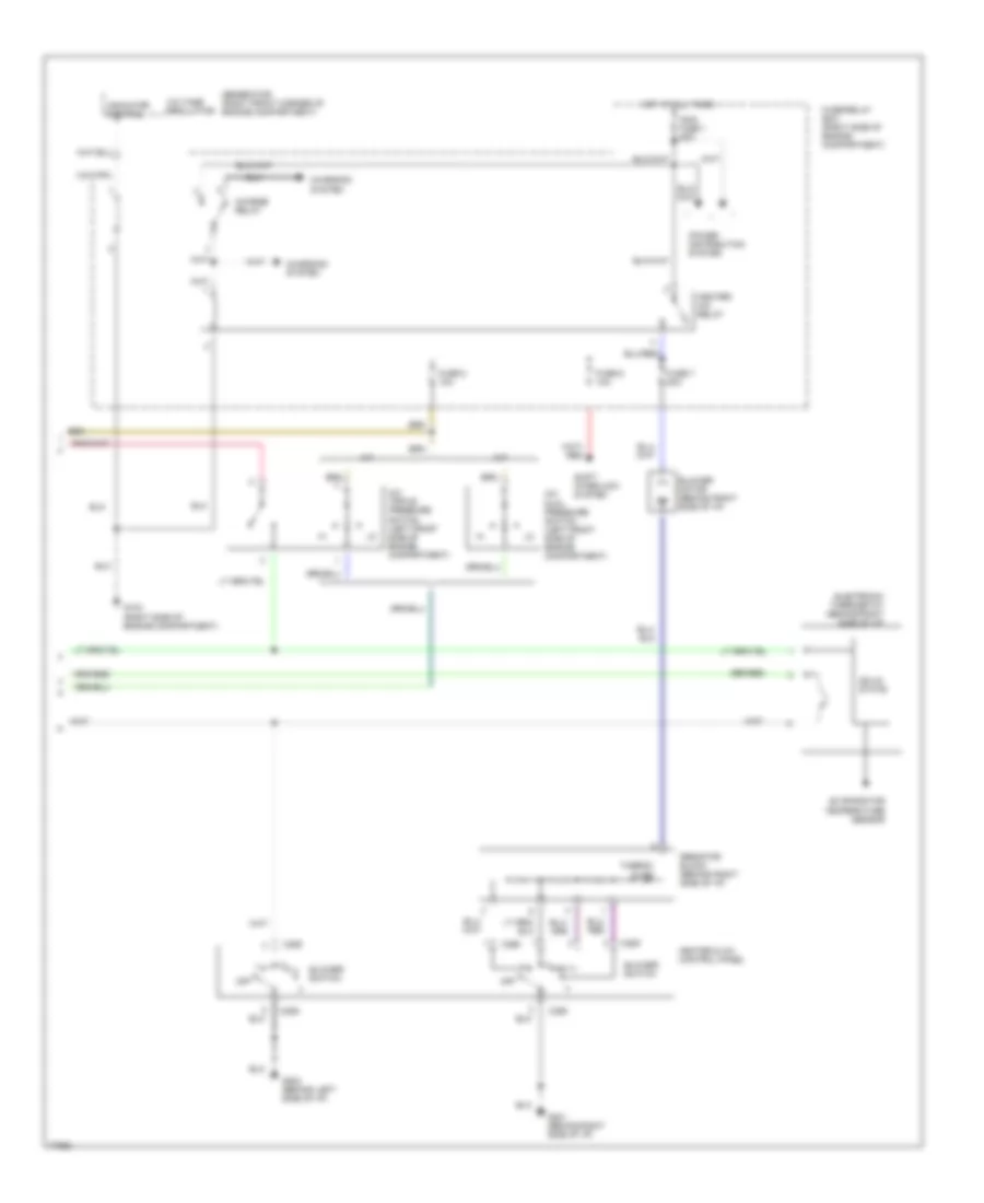
3.2L, A/C Wiring Diagram, Late Production (1 of 2) for Isuzu Rodeo S 1995
List of elements for 3.2L, A/C Wiring Diagram, Late Production (1 of 2) for Isuzu Rodeo S 1995:
- A/c compressor clutch
- A/c compressor relay
- A/c compressor relay cntl
- A/c compressor relay input
- A/c on input
- A/c switch
- A/c thermo switch (left front corner of engine compartment)
- Cond fan fuse 30a
- Condenser fan (right front side of engine compartment)
- Condenser fan relay
- Engine control module (ecm) (behind left side kick panel)
- Fuse/ relay box
- Fuse/relay box
- G125 (front center of engine)
- Hot at all times
- Noise condenser (right front side of engine compartment)
- Thermo switch relay
- Transmission control module (behind left side of i/p)
3.2L, A/C Wiring Diagram, Late Production (2 of 2) for Isuzu Rodeo S 1995
List of elements for 3.2L, A/C Wiring Diagram, Late Production (2 of 2) for Isuzu Rodeo S 1995:
- A/c dual pressure switch (left front side of engine compartment)
- A/c triple pressure switch (left front side of engine compartment)
- A/t
- Air con fuse 10a
- Alternator (right front corner of engine compartment)
- Blower fuse 20a
- Blower motor (behind right side of i/p)
- Blower switch
- Charge fuse 10a
- Charge relay
- Charging system
- Electronic thermostat (behind right side of i/p)
- Evaporator temperature sensor
- Fan control switch
- Fuse/relay box
- G103 (right side of engine compartment)
- G203 (right kick panel)
- Heater- a/c relay
- Hot at all times
- Indicator control
- M/t
- Main fuse 100a
- Off
- Resistor block (behind right side of i/p)
- Solid state
- Thermo fuse
- Voltage regulator
Heater Wiring Diagram, Early Production for Isuzu Rodeo S 1995
List of elements for Heater Wiring Diagram, Early Production for Isuzu Rodeo S 1995:
- 1995 vftc c
- Blower motor (behind right side of i/p)
- Blower switch
- C289
- C290
- Charge relay
- Charging system
- Fuse 6 10a
- Fuse 7 20a
- Fuse/relay box (right side of engine compartment)
- G103 (right side of engine compartment)
- G201 (behind right side of i/p)
- Generator (right front corner of engine compartment)
- Heater control panel
- Heater relay
- Hot at all times
- Indicator control
- Main fuse 1 60a
- Off
- Power distribution system
- Resistor block (behind right side of i/p)
- Shift interlock system
- Thermo fuse
- Voltage regulator
Heater Wiring Diagram, Late Production for Isuzu Rodeo S 1995
List of elements for Heater Wiring Diagram, Late Production for Isuzu Rodeo S 1995:
- (right kick panel)
- 1995 vftc c
- Blower
- Blower motor (behind right side of i/p)
- Blower switch
- Charge fuse 10a
- Charge relay
- Charging system
- Fuse 20a
- Fuse/relay box (right side of engine compartment)
- G103 (right side of engine compartment)
- G203
- Generator (right front corner of engine compartment)
- Heater control panel
- Heater relay
- Hot at all times
- Indicator control
- Main fuse 1 60a
- Off
- Resistor block (behind right side of i/p)
- Thermo fuse
- Voltage regulator
ANTI-LOCK BRAKES
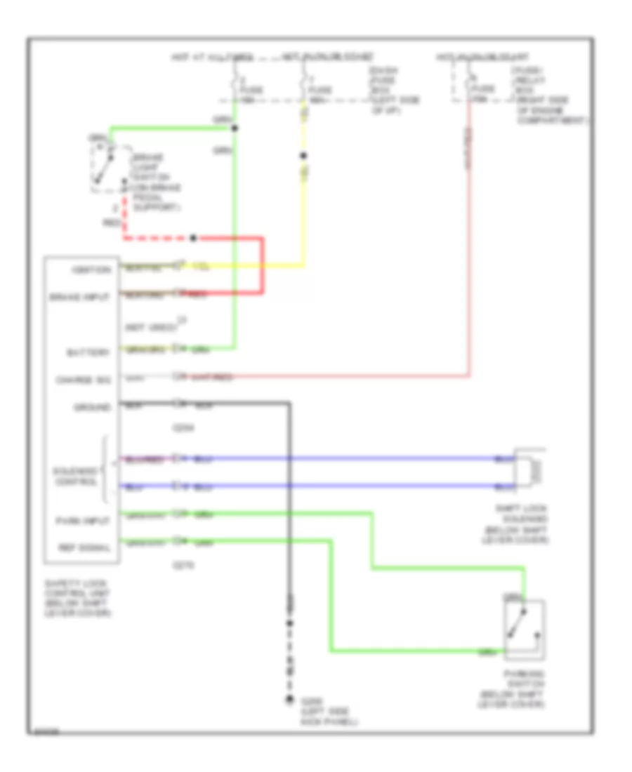
Anti-lock Brake Wiring Diagrams, Early Production for Isuzu Rodeo S 1995
List of elements for Anti-lock Brake Wiring Diagrams, Early Production for Isuzu Rodeo S 1995:
- (3.2l)
- (below right front seat)
- (left kick panel)
- (right side of trans)
- (top of brake pedal support)
- 2.6l
- 3.2l
- 4
- 4wd ind in
- 4wd indicator switch
- A/t
- Br sw in
- Brake lamp switch
- Brake warning indicator
- Combination valve pressure differential switch (left rear of eng compartment)
- D.g. connector (left kick panel)
- D.g. in
- Differential speed sensor (rear of transmission)
- Diode box d (behind left side of i/p)
- Dump sol
- Dump solenoid
- Fuse 13 20a
- Fuse 2 10a
- Fuse 7 10a
- G101 (right front fender)
- G301 (below right front seat)
- Ground
- Hot at all times
- Hot in acc or on
- Hot in on or start
- Ignition in
- Indicators
- Instrument cluster
- Isolation sol
- Isolation solenoid
- M/t
- Nca
- Press diff in
- Pwr in
- Rear anti-lock indicator
- Rear wheel anti-lock brake controller
- Red
- Reset
- Reset sw
- Rwal ind
- Rwal brake valve (right front fender)
- Speed hi in
- Speed lo in
- Stop lights
- Test connector
- Under-dash fuse/relay box
- Warn
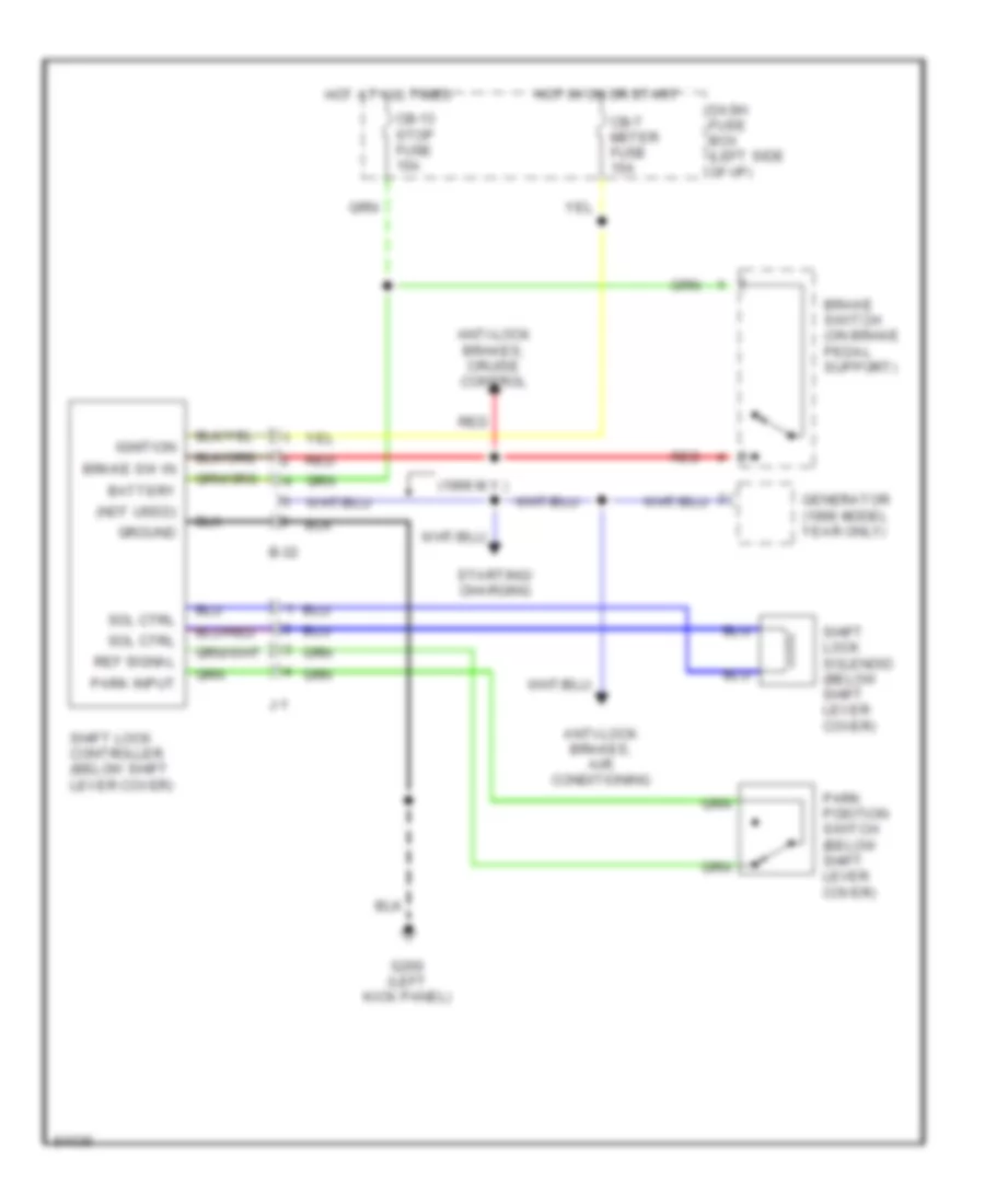
Anti-lock Brake Wiring Diagrams, Late Production for Isuzu Rodeo S 1995
List of elements for Anti-lock Brake Wiring Diagrams, Late Production for Isuzu Rodeo S 1995:
- (below right front seat)
- (left kick panel)
- (right side of trans)
- (top of brake pedal support)
- 15a
- 2.6l
- 20a
- 3.2l
- 4wd ind in
- 4wd indicator switch
- A/t
- All a/t, m/t
- Br sw in
- Brake differential switch (left rear of eng compartment)
- Brake light switch
- Brake switch
- Brake warning indicator
- D.g. in
- Differential speed sensor (rear of transmission)
- Diode box d (behind left side of i/p)
- Dump sol
- Dump solenoid
- G101 (right front fender)
- G104 (rear of left front fender)
- G301 (below right front seat)
- Ground
- Hot at all times
- Hot in acc or on
- Hot in on or start
- I-15
- I-16
- Ignition in
- Indicators
- Instrument cluster
- Isolation sol
- Isolation solenoid
- M/t
- M/t w/o cruise
- Meter cb-7
- Nca
- Parking brake switch
- Press diff in
- Pwr in
- Rear anti-lock indicator
- Rear wheel anti-lock brake controller
- Red
- Reset
- Reset sw
- Rwal ind
- Rwal brake valve (right front fender)
- Rwal cb-23
- Rwal diagnostic connector
- Speed hi in
- Speed lo in
- Stop cb-13
- Stop lights
- Test connector
- Under-dash fuse/relay box
- W/ cruise
- Warn
COMPUTER DATA LINES
2.6L
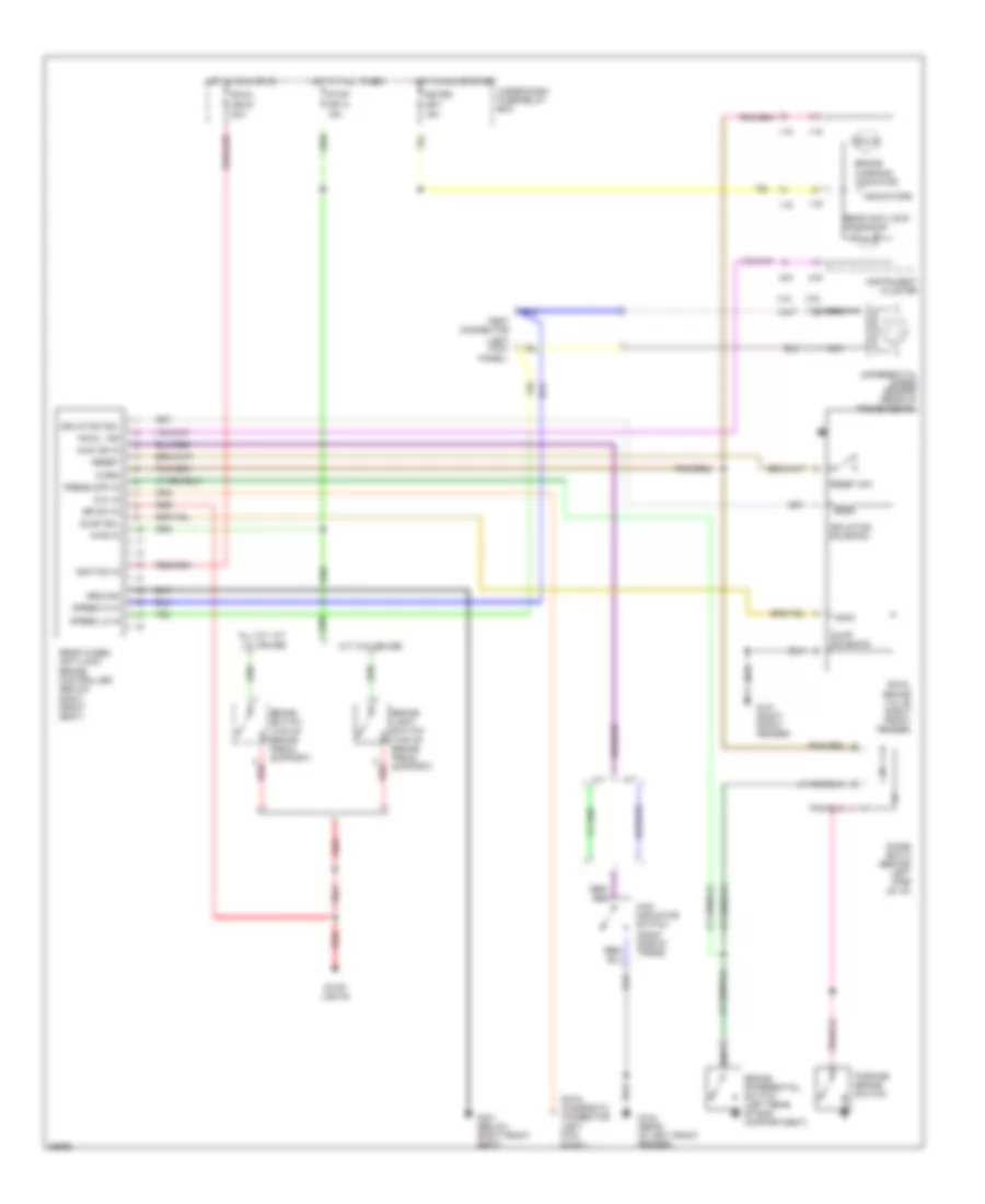
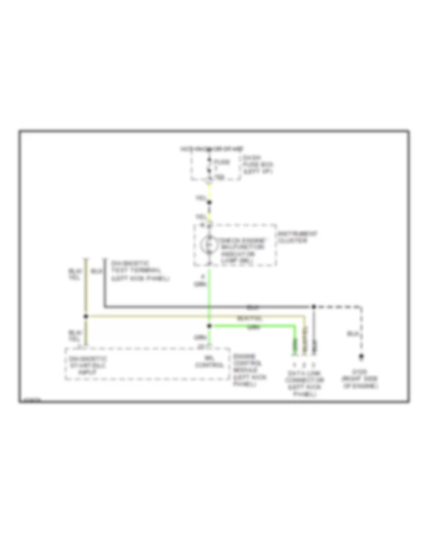
2.6L, Computer Data Lines, Early Production for Isuzu Rodeo S 1995
List of elements for 2.6L, Computer Data Lines, Early Production for Isuzu Rodeo S 1995:
- "check engine" malfunction indicator lamp (mil)
- (left kick panel)
- (right side of engine)
- Dash fuse box (left i/p)
- Data link connector (left kick panel)
- Diagnostic start/dlc input
- Diagnostic test terminal
- Engine control module (left kick panel)
- Fuse 10a
- G120
- Hot in on or start
- Instrument cluster
- Mil control
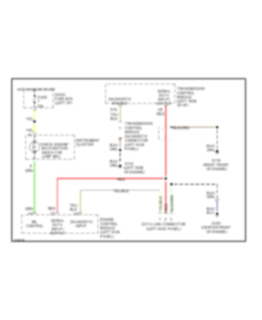
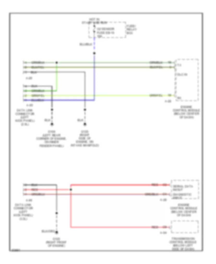
2.6L, Computer Data Lines, Late Production for Isuzu Rodeo S 1995
List of elements for 2.6L, Computer Data Lines, Late Production for Isuzu Rodeo S 1995:
- A-26
- A-28
- A-64
- A-65
- A-66
- Data link connector (left kick panel) (2.6l)
- Data link connector (left kick panel) (3.2l)
- Diagnostic input
- Dlc in
- Engine control module (below center of dash)
- Fuse eb-10 10a
- Fuse/ relay box
- G104 (left rear corner of engine, on inner fender panel)
- G120 (right side of engine, on intake manifold)
- G125 (right front of engine)
- Hot in start and run
- O2 sensor
- Red
- Serial data in/out
- Transmission control module (below left side of dash)
3.2L
3.2L, Computer Data Lines, Early Production for Isuzu Rodeo S 1995
List of elements for 3.2L, Computer Data Lines, Early Production for Isuzu Rodeo S 1995:
- "check engine" malfunction indicator lamp (mil)
- (center front
- (left kick panel)
- (right front
- C8 red
- D16
- Dash fuse box (left i/p)
- Data link connector
- Diagnostic enable
- Diagnostic input
- Engine control module (left kick panel)
- Fuse 10a
- G112 (left side of engine)
- G119
- G125
- Hot in on or start
- Instrument cluster
- Mil control
- Of engine)
- Red
- Serial data input/ output
- Transmission control module (left side of i/p)
- Transmission control module diagnostic connector (left kick panel)
3.2L, Computer Data Lines, Late Production for Isuzu Rodeo S 1995
List of elements for 3.2L, Computer Data Lines, Late Production for Isuzu Rodeo S 1995:
- A-26
- A-28
- A-64
- A-65
- A-66
- Data link connector (left kick panel) (2.6l)
- Data link connector (left kick panel) (3.2l)
- Diagnostic input
- Dlc in
- Engine control module (below center of dash)
- Fuse eb-10 10a
- Fuse/ relay box
- G104 (left rear corner of engine, on inner fender panel)
- G120 (right side of engine, on intake manifold)
- G125 (right front of engine)
- Hot in start and run
- O2 sensor
- Red
- Serial data in/out
- Transmission control module (below left side of dash)
COOLING FAN
3.2L
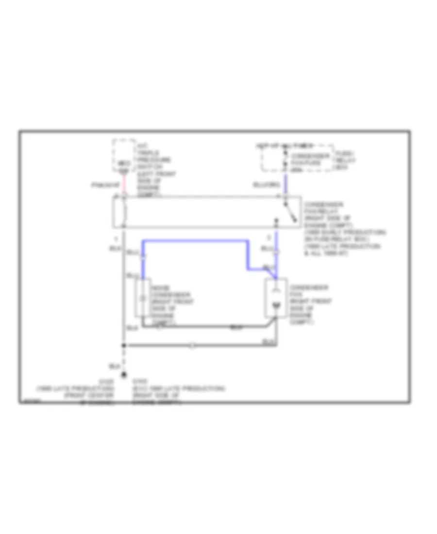
3.2L, Cooling Fan Wiring Diagram for Isuzu Rodeo S 1995
List of elements for 3.2L, Cooling Fan Wiring Diagram for Isuzu Rodeo S 1995:
- A/c triple pressure switch (left front side of engine compt)
- Condenser fan (right front side of engine compt)
- Condenser fan fuse 30a
- Condenser fan relay (right side of engine compt) (1995 early production) (in fuse/relay box) (1995 late production & all 1996-97)
- Fuse/ relay box
- G103 (exc 1995 late production) (right side of engine compt)
- G125 (1995 late production) (front center of engine)
- Hot at all times
- Med sw
- Noise condenser (right front side of engine compt)
CRUISE CONTROL
Cruise Control Wiring Diagram, Early Production for Isuzu Rodeo S 1995
List of elements for Cruise Control Wiring Diagram, Early Production for Isuzu Rodeo S 1995:
- (a/t)
- (m/t)
- 10a
- Automatic transmission mode switch (beneath vehicle, on left side of transmission)
- Brake switch (on brake pedal support)
- Clutch interrupt switch (top of clutch pedal support)
- Cruise control pump/ actuator (right rear corner of engine compartment)
- Cruise control switch
- Cruise control unit (right side kick panel)
- Dash fuse box (left side of i/p)
- Fuse 2
- Fuse 5
- Fuse 8
- G101 (middle of right front fender)
- G201 (right side of i/p, above kick panel)
- Hot at all times
- Hot in on or start
- Instrument cluster
- Nca
- Neutral switch (beneath vehicle, on right side of transmission)
- Off
- Red
- Resume/ accel
- Safety valve
- Set/ coast
- Transmission system
- Vacuum pump
- Vehicle speed output
- Vent valve
Cruise Control Wiring Diagram, Late Production for Isuzu Rodeo S 1995
List of elements for Cruise Control Wiring Diagram, Late Production for Isuzu Rodeo S 1995:
- (a/t)
- (m/t)
- A63
- Automatic transmission mode switch (left side of transmission)
- Back up, turn fuse cb 15 15a
- Brake input
- Brake switch
- Cancel
- Cancel input vacuum valve control
- Clutch switch
- Cruise control main switch
- Cruise control pump/actuator (right rear of engine compartment)
- Cruise control switch (combination switch)
- Cruise control unit (right kick panel)
- Cruise ind control
- Cruise main ind
- Cruise on output
- Cruise set ind
- Dash fuse box (left side of i/p)
- Disengage input
- Disengage output
- Elec ig fuse cb 12 10a
- Elec, ig fuse cb 12 15a
- G119 (right front of engine)
- G200 (left kick panel)
- G203 (right
- Gauge assembly
- Ground
- Hot at all times
- Hot in on or start
- I-15
- I-26
- Ignition input
- Kick panel)
- Meter fuse cb 7 15a
- Off
- Red
- Resume/ accel
- Resume/ accel input
- Safety valve
- Set/ coast
- Set/coast input
- Stop fuse cb 13 15a
- Transmission control module (below left side of dash)
- Vacuum pump
- Vacuum pump control
- Vacuum pump/valve control cruise on input
- Vehicle speed input
- Vehicle speed output
- Vent valve
DEFOGGERS
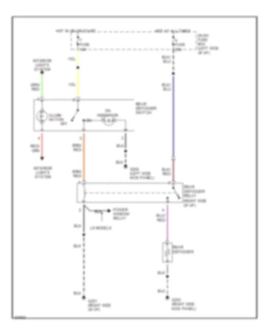
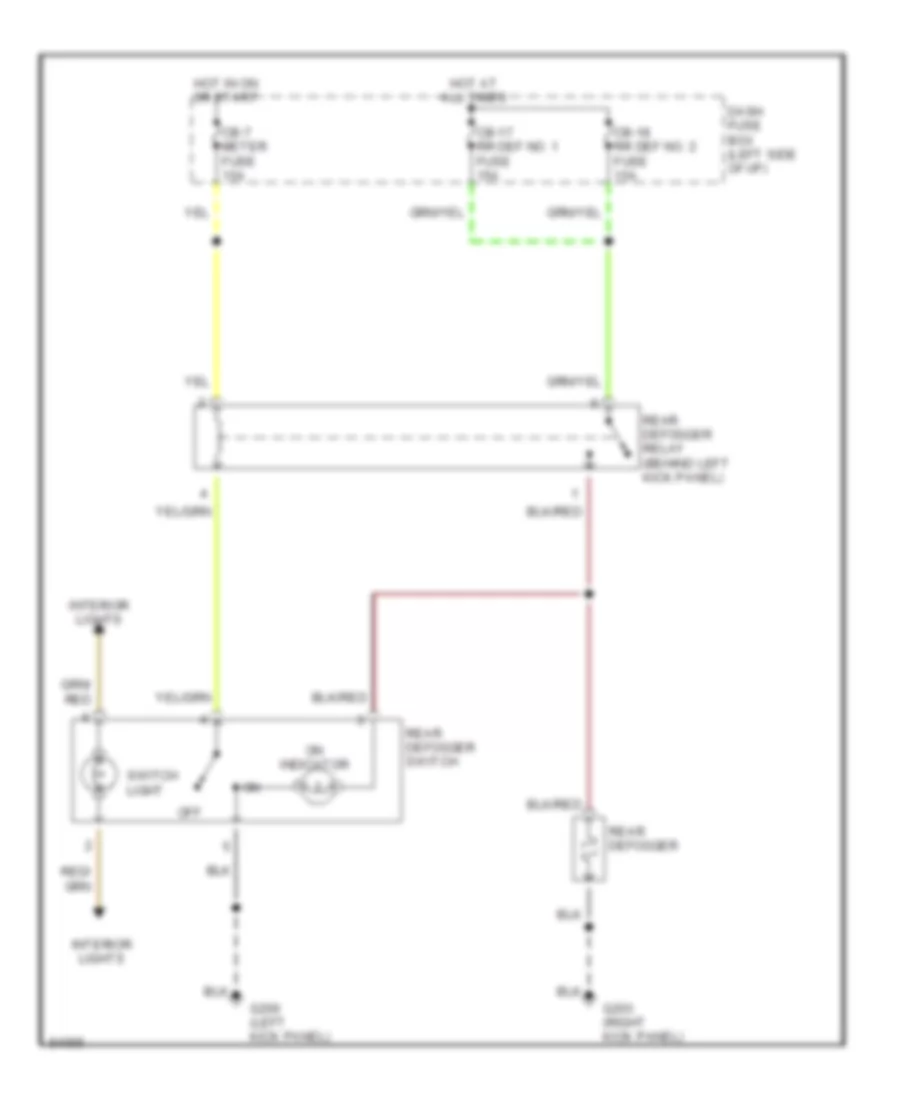
Defogger Wiring Diagram, Early Production for Isuzu Rodeo S 1995
List of elements for Defogger Wiring Diagram, Early Production for Isuzu Rodeo S 1995:
- (right side of i/p)
- Dash fuse box (left side of i/p)
- Fuse 10a
- Fuse 25a
- G200 (left side kick panel)
- G201 (right side of i/p)
- G203 (right side kick panel)
- Hot at all times
- Hot in on or start
- Illumi- nation
- Interior lights system
- Ls models
- Off
- On indicator
- Power window relay
- Rear defogger
- Rear defogger relay
- Rear defogger switch
Defogger Wiring Diagram, Late Production for Isuzu Rodeo S 1995
List of elements for Defogger Wiring Diagram, Late Production for Isuzu Rodeo S 1995:
- Cb-17 rr def no. 1 fuse 15a
- Cb-18 rr def no. 2 fuse 15a
- Cb-7 meter fuse 15a
- Dash fuse box (left side of i/p)
- G200 (left kick panel)
- G203 (right kick panel)
- Hot at all times
- Hot in on or start
- Interior lights
- Off
- On indicator
- Rear defogger
- Rear defogger relay (behind left kick panel)
- Rear defogger switch
- Switch light
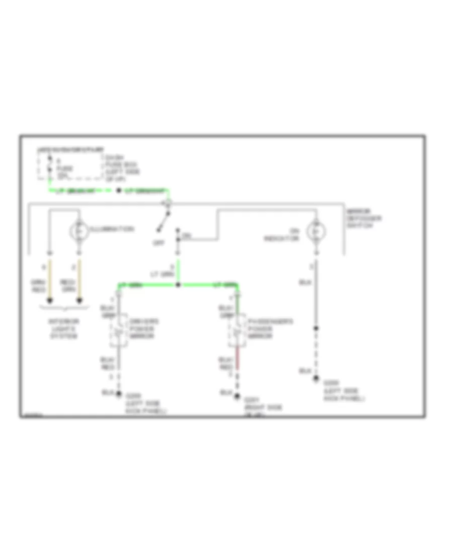
Heated Mirrors Wiring Diagram, Early Production for Isuzu Rodeo S 1995
List of elements for Heated Mirrors Wiring Diagram, Early Production for Isuzu Rodeo S 1995:
- (left side kick panel)
- Dash fuse box (left side of i/p)
- Driver's power mirror
- Fuse 15a
- G200
- G200 (left side kick panel)
- G201 (right side of i/p)
- Hot in on or start
- Illumination
- Interior lights system
- Mirror defogger switch
- Off
- On indicator
- Passenger's power mirror
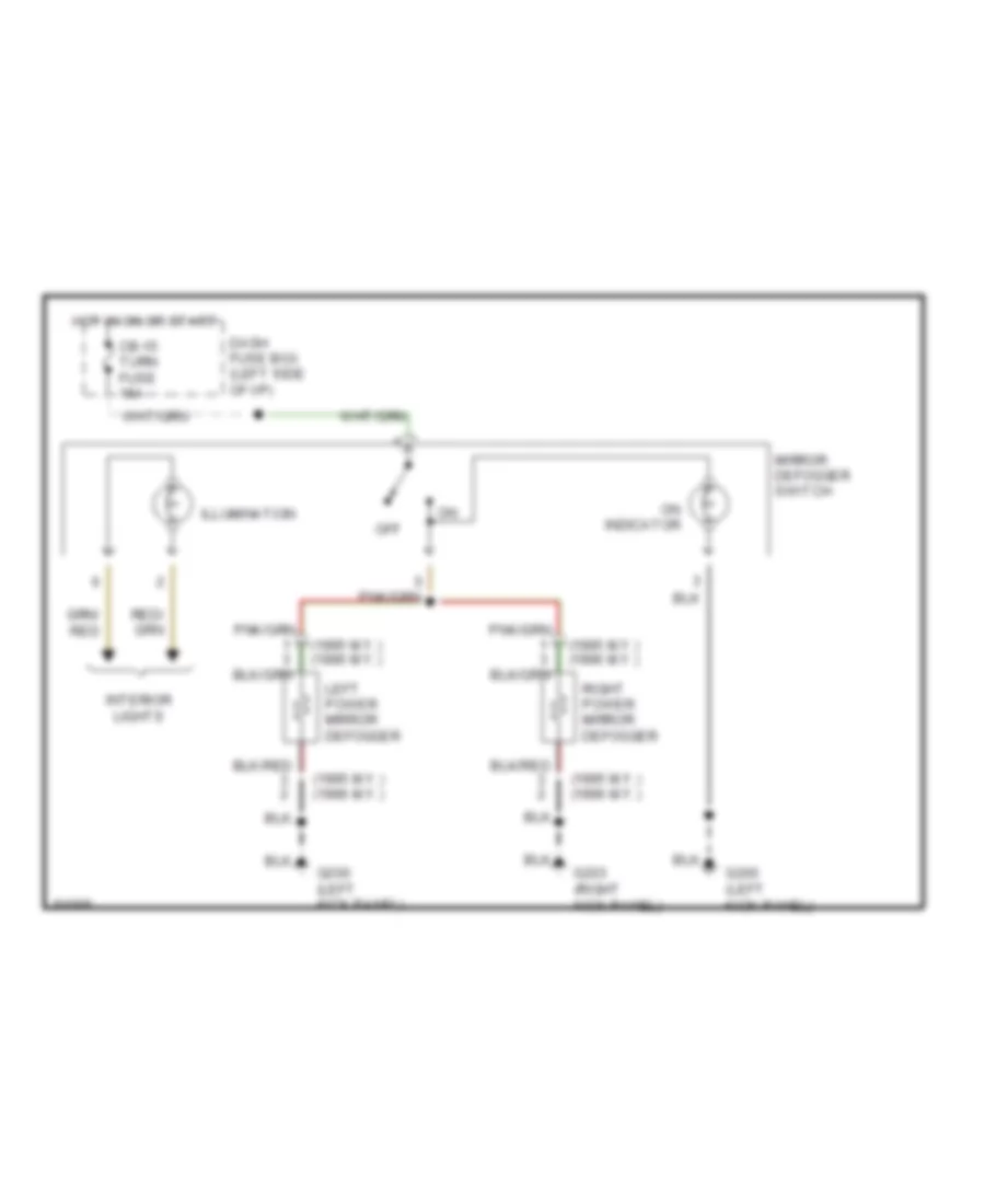
Heated Mirrors Wiring Diagram, Late Production for Isuzu Rodeo S 1995
List of elements for Heated Mirrors Wiring Diagram, Late Production for Isuzu Rodeo S 1995:
- (1995 m.y.) (1996 m.y.)
- Cb-15 turn fuse 15a
- Dash fuse box (left side of i/p)
- G200 (left kick panel)
- G203 (right kick panel)
- Hot in on or start
- Illumination
- Interior lights
- Left power mirror defogger
- Mirror defogger switch
- Off
- On indicator
- Right power mirror defogger
ENGINE PERFORMANCE
2.6L
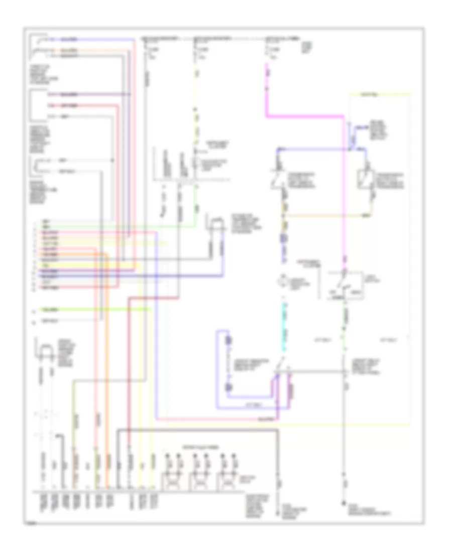
2.6L, Engine Performance Wiring Diagrams (1 of 3) for Isuzu Rodeo S 1995
List of elements for 2.6L, Engine Performance Wiring Diagrams (1 of 3) for Isuzu Rodeo S 1995:
- (at left kick panel)
- (below left side of i/p at kick panel)
- (top of engine)
- A/c-switch
- Air conditioning system
- Air vsv control
- Braided
- C210
- C211
- Connector
- Crank signal
- Crankshaft pos sens
- Dash fuse box
- Data link
- Diagnostic test terminal
- Dlc serial data
- Ect sensor ground
- Ect sensor input
- Egr cut vsv control
- Egr duty sol control
- Engine control module (ecm)
- Engine speed input
- Evap canister vsv ctrl
- Fuel inj #1 control
- Fuel inj #2 control
- Fuel inj #3 control
- Fuel inj #4 control
- Fuel injector #1
- Fuel injector #2
- Fuel injector #3
- Fuel injector #4
- Fuel pres ctrl vsv
- Fuse 11 10a
- Fuse 3 10a
- Fuse 7 10a
- Fuse 8 10a
- G120 (right side of engine)
- Ground
- Ho2s input
- Ho2s shield ground
- Hot at all times
- Hot in on or start
- Hot in start
- Ignition power
- Instrument cluster
- Maf sensor ground
- Maf sensor input
- Maf sensor power
- Mafs shield cround
- Malfunction indicator lamp (mil)
- Map sens grd
- Map sens input
- Map sens ref volt.
- Memory power
- Mil control
- Monitor
- Not
- Red
- Used
- Vehicle speed input
- Wot sw idle position
- Wot sw-wot position
2.6L, Engine Performance Wiring Diagrams (2 of 3) for Isuzu Rodeo S 1995
List of elements for 2.6L, Engine Performance Wiring Diagrams (2 of 3) for Isuzu Rodeo S 1995:
- (left front corner of engine compartment)
- (lower right side of engine)
- (right side of engine compartment)
- (top center of engine)
- Air flow sensor (left front of engine compartment)
- Air management valve (amv)
- Braided
- C274
- California models
- Diode box b
- Engine control module (ecm) relay
- Engine coolant temperature (ect) sensor
- Evaporative emission canister purge vacuum switching valve
- Exhaust gas recirculation (egr) duty solenoid
- Exhaust gas recirculation (egr) vacuum switching valve
- Fuel pressure control valve vacuum switching valve
- Fuse 1 15a
- Fuse/ relay box
- G105 (right side of engine compartment)
- Ground
- Hot at all times
- Idle
- Instrument cluster
- Manifold absolute pressure (map) sensor (right side of engine compartment)
- Not used
- Output
- Power
- Red
- To fuse 2
- Vehicle speed sensor
- Wide open throttle (wot) switch (top center of engine)
- Wot
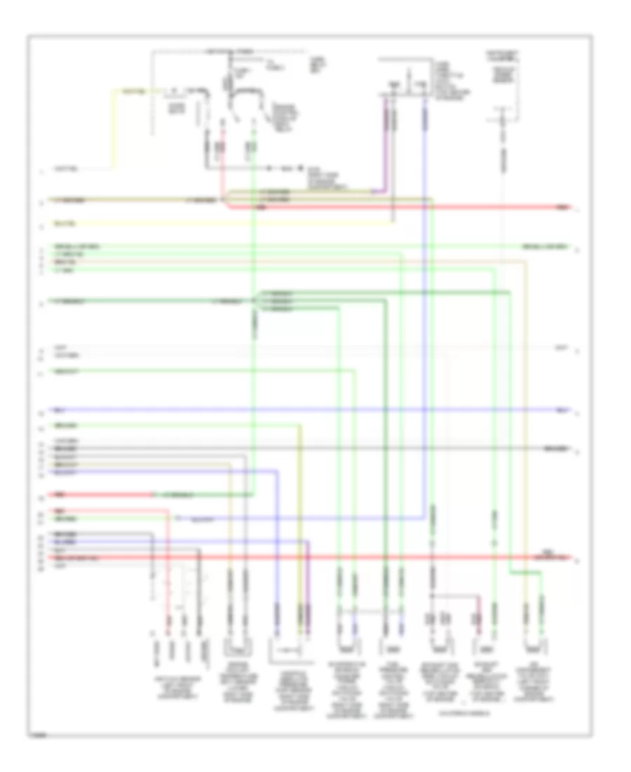
2.6L, Engine Performance Wiring Diagrams (3 of 3) for Isuzu Rodeo S 1995
List of elements for 2.6L, Engine Performance Wiring Diagrams (3 of 3) for Isuzu Rodeo S 1995:
- (right rear corner oif engine)
- A/c system
- Air regulator (underside of vehicle, right side of engine)
- Braided
- C274
- Charge relay
- Crank position sensor (underside of vehicle, right rear of engine)
- Dash fuse box
- Diode box a
- Distributor assembly
- Distributor cap
- From oil pressure switch
- Fuel pump (underside of vehicle, right front of fuel tank)
- Fuel pump relay
- Fuse 2 20a
- Fuse 5 10a
- Fuse 5 20a
- Fuse 6 10a
- Fuse 9 15a
- Fuse/relay box
- G104 (left rear corner of engine compartment)
- G105 (right side of engine compartment)
- G119 (right front corner of engine)
- G120 (right side of engine)
- G409 (underside of vehicle, behind center of rear bumper)
- Generator (lower left front of engine)
- Ground
- Heated oxygen sensor (ho2s) (lower left side of engine)
- Hot at all times
- Hot in on or start
- Hot in start
- Ignition coil (center rear of engine compartment)
- Indicator control
- Instrument cluster
- Main fuse 1 60a
- Not used
- Power
- Power signal input
- Power switch (underside of vehicle, right side of engine)
- Primary
- Primary winding control
- Radio noise suppressor (center rear of engine compartment)
- Red
- Reference voltage
- Secondary
- Signal output
- Starting/ charging
- System
- Tachometer test connector (not used) (right side of engine compartment)
- Timer core
- To fuse 1
- Voltage regulator
3.2L
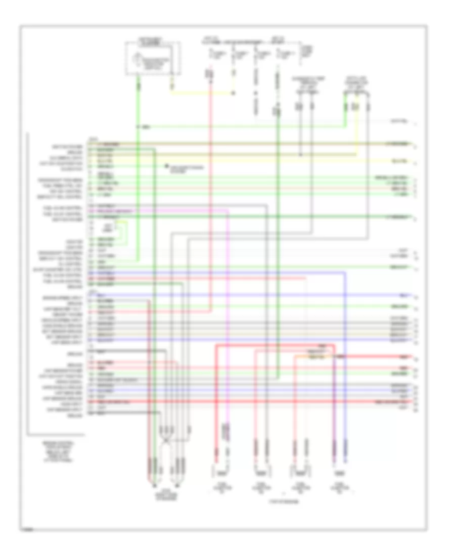
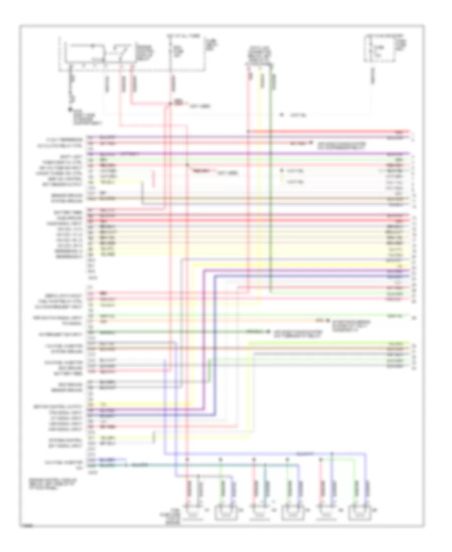
3.2L, Engine Performance Wiring Diagrams (1 of 3) for Isuzu Rodeo S 1995
List of elements for 3.2L, Engine Performance Wiring Diagrams (1 of 3) for Isuzu Rodeo S 1995:
- "check eng" mil ctrl
- (m/t only)
- (not used)
- 1 & 2 fuel injector
- 3 & 4 fuel injector
- 5 & 6 fuel injector
- 5 volt reference
- A/c clutch relay ctrl
- A/c request sig input
- A10
- A11
- A12
- Air conditioning system (a/c compressor relay)
- Air conditioning system (a/c thermostat relay)
- B10
- B11
- B12
- Battery feed
- Bypass control
- C10
- C11
- C12
- C13
- C14
- C15
- C16
- C218
- C219
- Canist purge vsv ctrl
- D10
- D11
- D12
- D13
- D14
- D15
- D16
- Dash fuse box
- Data link connector (below left side of i/p, at kick panel)
- Dlc diag request input
- Ecm fuse 30a
- Ecm ground
- Ect sensor output
- Ect signal input
- Egr vsv control
- Engine control module (below left side of i/p, at kick panel)
- Engine control module relay
- Fuel injectors (top of engine)
- Fuel pump relay ctrl
- Fuse 10a
- Fuse/ relay box
- G105 (right side of engine compartment)
- Ho2s ground
- Ho2s signal input
- Hot at all times
- Hot in on or start
- Iac coil "a" hi
- Iac coil "a" lo
- Iac coil "b" hi
- Iac coil "b" lo
- Iat signal input
- Ign voltage sig input
- Ignition control output
- Map signal input
- N/a
- P/n signal
- Psp switch signal input
- Red
- Reference hi
- Reference lo
- Sensor ground
- Serial data in/out
- Shift light
- Starting/charging system (a/t only) (diode box a)
- System ground
- Tps signal input
- Vss signal input
3.2L, Engine Performance Wiring Diagrams (2 of 3) for Isuzu Rodeo S 1995
List of elements for 3.2L, Engine Performance Wiring Diagrams (2 of 3) for Isuzu Rodeo S 1995:
- (a/t)
- (m/t)
- Braided
- C234
- Coolant temp in
- D14
- Data in serial
- Evaporative emission canister purge vacuum switching valve (center rear of engine)
- Exhaust gas recirculation (egr) vacuum switching valve (top center rear of engine)
- Fuel pump (underside of vehicle, right front of fuel tank)
- Fuel pump relay
- Fuse 10a
- Fuse 15a
- Fuse/ relay box
- Fuse/relay box
- G104 (left rear of engine compartment)
- G105 (right side of engine compartment)
- G125 (center front of engine)
- G409 (underside of vehicle, center of rear bumper)
- Ground
- Heated oxygen sensor (underside of vehicle, left side of transmission)
- Hot at all times
- Idle air control valve (top left side of engine)
- Power steering pressure switch (lower left front corner of engine compartment)
- Red
- Tps input
- Transmission control module (tcm) (behind i/p, top of left kick panel)
- W/ a/t
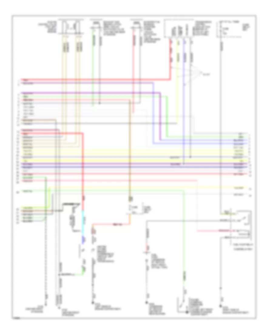
3.2L, Engine Performance Wiring Diagrams (3 of 3) for Isuzu Rodeo S 1995
List of elements for 3.2L, Engine Performance Wiring Diagrams (3 of 3) for Isuzu Rodeo S 1995:
- C176
- C177
- C178
- C274
- C275
- Cluster
- Crank position sensor (lower right side of engine)
- Crnk pos sens in
- Cruise control system (neutral switch)
- Ctrl in bypass
- Ctrl in ignition
- Dash fuse box
- Electronic ignition (ei) system (center front of engine)
- Engine coolant temperature sensor (rear of engine)
- Fuse 10a
- Fuse 15a
- G105 (right side of engine compartment)
- G125 (top center front of engine)
- Ground
- Head
- Hi out ign ref
- Hot at all times
- Hot in on or start
- Ignition coils
- Instrument
- Instrument cluster
- Intake air temperature (iat) sensor (top right side of engine)
- Light switch
- Lo out ign ref
- M/t only
- Malfunction indicator lamp
- Manifold absolute pressure sensor (top right side of engine)
- Nca
- Off
- Output speedometer
- Park
- Power ignition
- Rpm out
- Sens in crnk pos
- Shield ground
- Spark plug wires
- Tachometer input
- Throttle position sensor (top left side of engine)
- Transmission switch 1-2 (left side of transmission)
- Transmission switch 3-4 (right side of transmission)
- Upshift indicator light
- Upshift relay (below right side of i/p, at kick panel)
- Upshift resistor (behind right side of i/p)
EXTERIOR LIGHTS
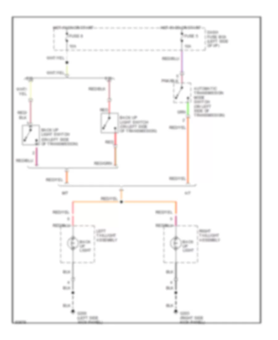
Back-up Lamps Wiring Diagram, Early Production for Isuzu Rodeo S 1995
List of elements for Back-up Lamps Wiring Diagram, Early Production for Isuzu Rodeo S 1995:
- (on left side of transmission)
- 10a
- 2.6l
- 3.2l
- A/t
- Automatic transmission mode switch (on left side of transmission)
- Back up light
- Back up light switch
- Back up light switch (on left side of transmission)
- Dash fuse box (left side of i/p)
- Fuse 5
- Fuse 8
- G200 (left side kick panel)
- G203 (right side kick panel)
- Hot in on or start
- Left taillight assembly
- M/t
- Red
- Red/
- Right taillight assembly
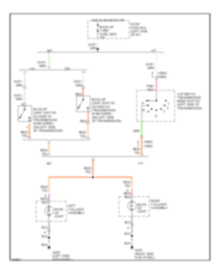
Back-up Lamps Wiring Diagram, Late Production for Isuzu Rodeo S 1995
List of elements for Back-up Lamps Wiring Diagram, Late Production for Isuzu Rodeo S 1995:
- (1995)
- (1996)
- (1996) (1995)
- 2.6l
- 3.2l
- A/t
- Automatic transmission mode switch (left side of transmission)
- Back- up light
- Back-up light switch (closed w/ transmission in reverse) (on left side of transmission)
- Back-up turn fuse cb15 15a
- Dash fuse box (left side of i/p)
- G200 (left side kick panel)
- G203 (right side kick panel)
- Hot in on or start
- Left taillight assembly
- M/t
- R n
- Red
- Right taillight assembly
Exterior Lamps Wiring Diagram, Early Production (1 of 2) for Isuzu Rodeo S 1995
List of elements for Exterior Lamps Wiring Diagram, Early Production (1 of 2) for Isuzu Rodeo S 1995:
- 10a
- 2.6l
- 3.2l
- A/t
- Automatic transmission mode switch (closed in reverse) (on left side of transmission)
- Back up light switch (closed w/ transmission in reverse) (on left side of transmission)
- Dash fuse box (left side of i/p)
- Fuse 1
- Fuse 5
- Fuse 8
- G104 (rear of left front fender)
- Head
- Hot at all times
- Hot in on or start
- Left front combination light
- Left front side marker light
- License light
- Light switch
- M/t
- Off
- Park
- Red
- Right front combination light
- Right front side marker light
- To headlights system
- To interior lights system
- Turn
Exterior Lamps Wiring Diagram, Early Production (2 of 2) for Isuzu Rodeo S 1995
List of elements for Exterior Lamps Wiring Diagram, Early Production (2 of 2) for Isuzu Rodeo S 1995:
- (2.6l) (3.2l)
- 10a
- 15a
- Anti-lock brakes system
- Back up light
- Brake light switch (on brake pedal support)
- Cruise control system
- Dash fuse box (left side of i/p)
- Flasher unit (behind left side of i/p, above kick panel)
- Fuse 2
- Fuse 3
- Fuse 7
- Fuse/ relay box (right side of eng compt, on inner fender panel)
- G200 (left side kick panel)
- G203 (right side kick panel)
- Gnd
- Hazard
- High mount stop light
- Hot at all times
- Hot in on or start
- Instrument cluster
- Left taillight assembly
- Left turn
- Off
- Output
- Park
- Power
- Red
- Right taillight assembly
- Right turn
- Stop
- Trailer connector (beneath vehicle, behind right rear corner of fuel tank)
- Turn
- Turn signal indic.
- Turn signal light
- Turn signal/ hazard warning switch (combination switch)
Exterior Lamps Wiring Diagram, Late Production (1 of 2) for Isuzu Rodeo S 1995
List of elements for Exterior Lamps Wiring Diagram, Late Production (1 of 2) for Isuzu Rodeo S 1995:
- 15a
- Combination switch
- Dash fuse box (left side of i/p)
- G104 (left rear corner of engine compartment, on inner fender panel)
- G200 (above left kick panel)
- G200 (left kick panel)
- Head
- Headlight switch
- Hot at all times
- Left front parking/ turn signal light
- Left front side marker light
- License light
- Off
- Park
- Right front parking/ turn signal light
- Right front side marker light
- Tail-illumi fuse cb5
- Taillight relay (left kick panel)
Exterior Lamps Wiring Diagram, Late Production (2 of 2) for Isuzu Rodeo S 1995
List of elements for Exterior Lamps Wiring Diagram, Late Production (2 of 2) for Isuzu Rodeo S 1995:
- (2.6l) (3.2l)
- 1-15 i-16
- 15a
- A/t & m/t w/ cruise
- Anti-lock brakes system
- Back-up turn fuse cb15 15a
- Brake or stop light switch (on brake pedal support)
- Combination switch
- Cruise control system
- Dash fuse box (left side of i/p)
- Flasher unit (above left kick panel)
- Fuse/ relay box (right side of eng compartment, on inner fender panel)
- G200 (above left kick panel)
- G200 (left side kick panel)
- G203 (right side kick panel)
- G415 (beneath center of vehicle, on frame rail)
- Gnd
- Hazard
- Hazard fuse eb1
- Hazard warning switch
- Hazard warning switch light
- High mount stop light
- Hot at all times
- Hot in on or start
- I-15
- I-16 i-16
- Ignition
- Interior lights system
- Left
- Left taillight
- Left turn indicator light
- M/t w/o cruise
- Meter assembly
- Off
- Output
- Park
- Red
- Right
- Right taillight
- Right turn indicator light
- Stop
- Stop fuse cb13 15a
- Trailer connector (behind center of rear bumper)
- Turn signal light
- Turn signal switch
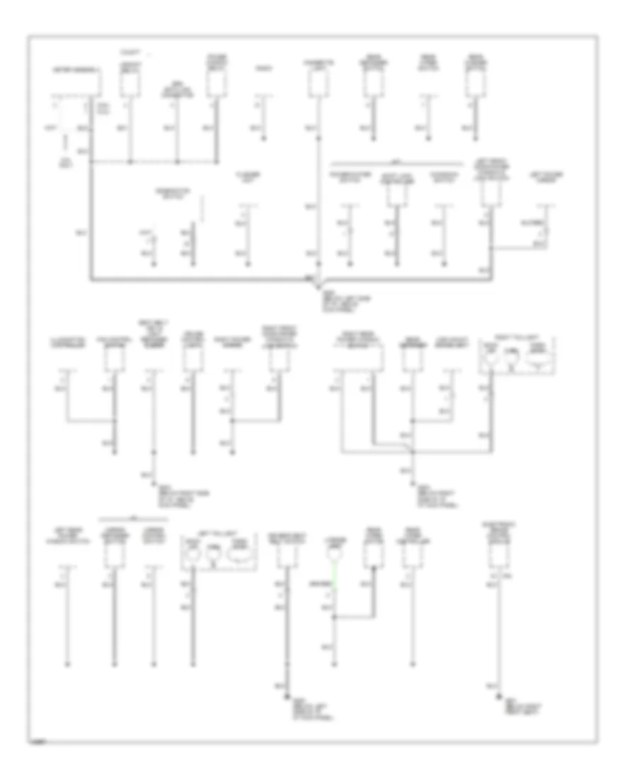
GROUND DISTRIBUTION
Ground Distribution Wiring Diagram, Early Production (1 of 4) for Isuzu Rodeo S 1995
List of elements for Ground Distribution Wiring Diagram, Early Production (1 of 4) for Isuzu Rodeo S 1995:
- (engine)
- (not used)
- (on right frame rail, at engine mount)
- 2.6l only
- 3.2l only
- 3.2l/v6
- A12
- Automatic transmission mode switch
- Battery
- Braided wire
- C12
- C149
- C15
- C218
- C219
- Data link connector
- Electronic ignition system
- Engine control module
- G101 (right front fender,behind battery)
- G102 (middle of left fender)
- G103 (middle of right fender)
- G104 (rear of left front fender)
- G112 (left side of engine on valve cover)
- G115 (valve cover)
- G119 (front of engine, behind steering pump)
- G119 (right front of engine)
- G120 (right side of engine on valve cover)
- G121 (center of safety wall)
- G130 (top left of transmission)
- G131 (front of intake manifold, behind coil pack)
- G131 (front right of intake manifold)
- Heated oxygen sensor
- Heated oxygen sensor shields
- Left front combination light
- Left front side marker light
- Right front combination light
- Right front side marker light
- Transmission control module shield
- Vehicle speed sensor
- Windshield washer motor
Ground Distribution Wiring Diagram, Early Production (2 of 4) for Isuzu Rodeo S 1995
List of elements for Ground Distribution Wiring Diagram, Early Production (2 of 4) for Isuzu Rodeo S 1995:
- (not used)
- 2.6l/l4 only
- 3.2l/v6 only
- 4wd indicator switch
- Braided wire
- C119
- C121
- C122
- C123
- C124
- C125
- C210
- C211
- Charge relay
- Condenser fan
- Condenser fan relay
- Crank position sensor
- Crank position sensor shield
- Cruise control pump/actuator
- Data link connector
- Diagnostic test terminal
- Engine control module
- Engine control module relay
- Fuel pump relay
- Fuse/relay box
- G101 (middle of right front fender)
- G120 (right side of engine, on intake manifold)
- Heater-a/c relay
- Noise condenser
- Rear wheel anti-lock brake valve
- Starter relay (m/t)
- Upshift relay pump/actuator
- Windshield wiper motor
- Windshield wiper relay or connector plug
Ground Distribution Wiring Diagram, Early Production (3 of 4) for Isuzu Rodeo S 1995
List of elements for Ground Distribution Wiring Diagram, Early Production (3 of 4) for Isuzu Rodeo S 1995:
- *3.2l
- **2.6l
- 2.6l only
- 3.2l only
- A/t
- Air regulator
- Automatic door lock control relay
- Automatic door lock switch
- C290
- C291
- Cigarette lighter
- Combination switch
- Cruise control unit
- Driver's power mirror
- Fast idle solenoid valve
- Flasher unit
- G112 (left side of engine, ahead of starter)
- G119 (right front of engine, behind steering pump)
- G200 (left side kick panel)
- G201 (right side of i/p)
- Heater-a/c control panel
- Illumination controller
- Instrument cluster
- Kickdown switch
- Left front power window switch
- Light switch
- Passenger's power mirror
- Power window relay
- Power/ winter switch
- Radio
- Rear defogger relay
- Rear defogger switch
- Rear wiper/washer switch
- Safety lock control unit
- Transmission control module
- Transmisson control module diagnostic connector
- Warning buzzer control unit
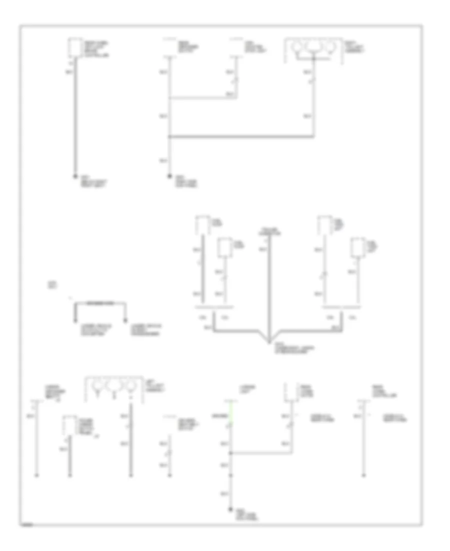
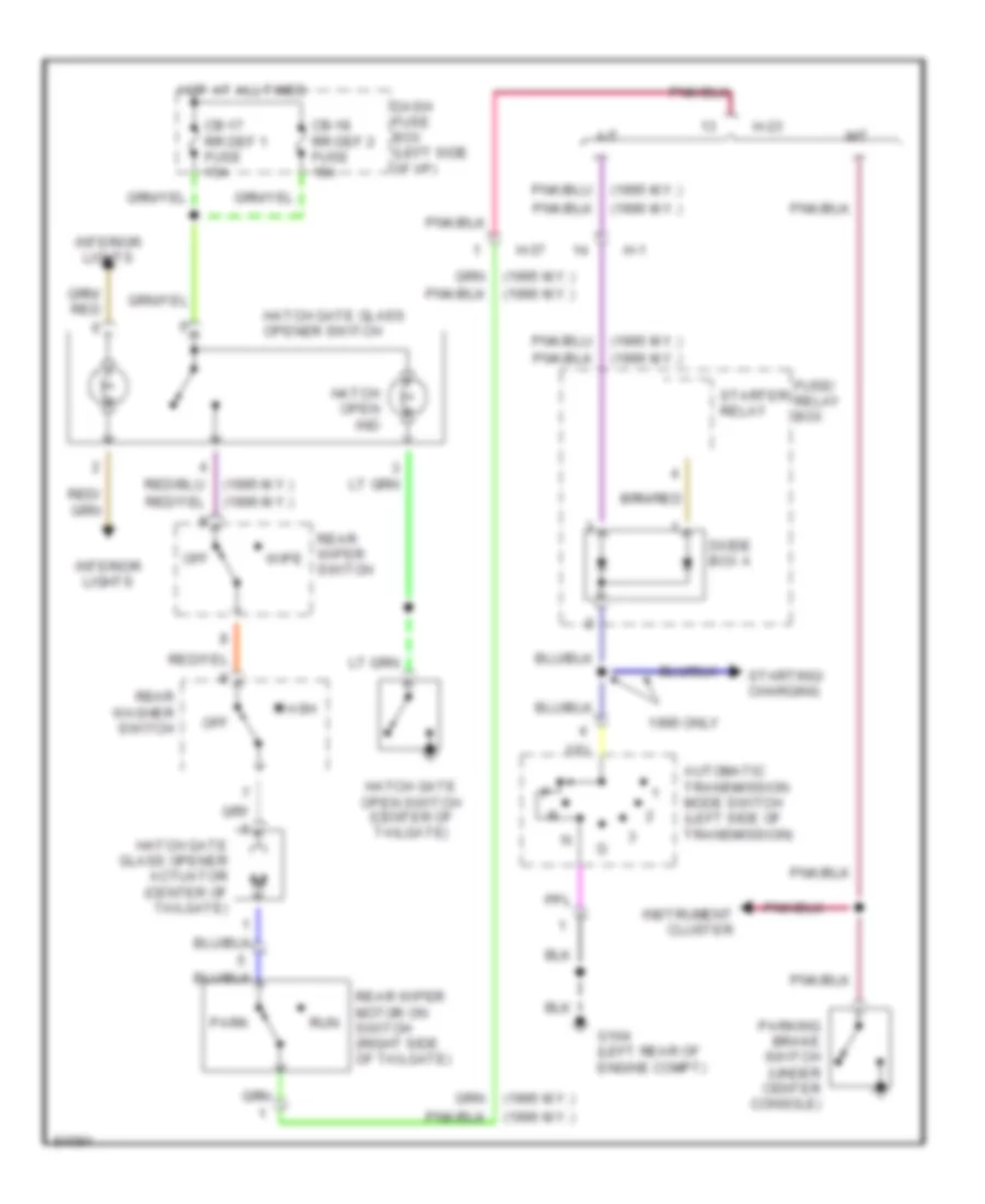
Ground Distribution Wiring Diagram, Early Production (4 of 4) for Isuzu Rodeo S 1995
List of elements for Ground Distribution Wiring Diagram, Early Production (4 of 4) for Isuzu Rodeo S 1995:
- (under vehicle, on body crossmember)
- (under vehicle, on catalytic converter)
- 2.6l
- 3.2l
- 4wd only
- Braided wire
- Driver's seat belt switch
- Fuel pump
- Fuel tank unit
- G200 (left side kick panel)
- G203 (right side kick panel)
- G301 (below right front seat)
- G415 (under body, ahead of rear bumper)
- High mounted stop light
- Left taillight assembly
- License light
- Mirror defogger switch
- Models w/ rear wiper
- Power mirror switch relay
- Rear defogger switch
- Rear wheel anti-lock brake controller
- Rear wiper controller
- Rear wiper motor
- Right taillight assembly
- Trailer connector
Ground Distribution Wiring Diagram, Late Production (1 of 3) for Isuzu Rodeo S 1995
List of elements for Ground Distribution Wiring Diagram, Late Production (1 of 3) for Isuzu Rodeo S 1995:
- (2.6l only)
- (3.2l only)
- (a/t only)
- (m/t) (a/t)
- (right side of engine compt, on inner fender panel)
- A-27
- A-28
- A-64
- A12
- Air regulator
- Battery
- Braided wire
- C12
- C15
- Condenser fan
- Condenser fan relay
- Cruise control pump actuator
- Data link connector
- Ecm main relay
- Electronic ignition assembly
- Engine control module
- Fast idle solenoid valve
- Fuel pump
- Fuel pump relay
- Fuse/ relay box
- G101 (right side of engine compt, behind battery)
- G102 (left side of engine compt, on inner fender panel)
- G103
- G112 (left side of engine, on valve cover)
- G112 (lower left side of engine, near oil pan)
- G115 (top center rear of engine, on valve cover)
- G119 (right front of engine)
- G119 (right front of engine, above generator)
- G119 (right front of engine, below intake manifold)
- G119 (right front of engine, on intake manifold)
- G120 (lower right side of engine compt, on frame)
- G120 (right side of engine, on valve cover)
- G121 (top center rear of engine compt, on bulkhead)
- G125 (center front of engine)
- G130 (lower left of engine compt, on top of transmission)
- G133 (lower center rear of engine)
- G134 (center front of engine)
- G302 (below center of i/p)
- G415 (beneath center rear of vehicle, on frame rail)
- H-11 h-13
- H-14
- Heated oxygen sensor
- Heated oxygen sensor shield
- Noise condenser
- Power switch
- Sensing & diagnostic module
- Tcm diagnostic connector
- Trailer lighting connector
- Transmission control module
- U-3
Ground Distribution Wiring Diagram, Late Production (2 of 3) for Isuzu Rodeo S 1995
List of elements for Ground Distribution Wiring Diagram, Late Production (2 of 3) for Isuzu Rodeo S 1995:
- (2.6l)
- (3.2l)
- 2.6l
- 3.2l
- 4wd indicator switch (3.2l only)
- A-27
- A-28
- A/t
- A/t mode switch
- A/t shift indicator control unit
- Braided wire
- Charge relay
- Crank position sensor shield
- Crankshaft position sensor
- Data link connector
- Ecm main relay
- Engine control module
- Fuel pump relay
- Fuel tank unit
- Fuse/ relay box
- Fuse/relay box
- G104 (left rear corner of engine compt, on inner fender panel)
- G105 (right side of engine compt, on inner fender panel)
- G131 (right side of engine, on intake manifold)
- Heated oxygen sensor
- Heater-a/c relay
- High note horn
- Intermittent windshield wiper relay or connector plug
- Left front combination light
- Left front side marker lamp
- Low note horn
- M/t
- Meter assembly
- Monitor (2.6l only)
- Rear wheel anti-lock brake valve
- Right front combination light
- Right front side marker lamp
- Starter relay
- Vehicle speed sensor
- Windshield washer sensor
- Windshield wiper motor
Ground Distribution Wiring Diagram, Late Production (3 of 3) for Isuzu Rodeo S 1995
List of elements for Ground Distribution Wiring Diagram, Late Production (3 of 3) for Isuzu Rodeo S 1995:
- (2.6l) (3.2l)
- 3.2l m/t
- 3.2l only
- A/t
- Back up
- Cigarette light
- Combination switch
- Cruise control unit
- Driver's seat belt switch
- Electronic brake control module
- Fan control switch
- Flasher unit
- G200 (below left side of i/p, above kick panel)
- G200 (below left side of i/p, at kick panel)
- G203 (below right side of i/p, at kick panel)
- G203 (below right side of i/p, above kick panel)
- G301 (below right front seat)
- High mount brake light
- Illumination controller
- Kickdown switch
- Left front door power window & lock switch
- Left power mirror
- Left rear power window switch
- Left taillight
- License light
- Meter assembly
- Mirror control switch
- Mirror defogger switch
- Park/ stop
- Power window relay
- Power/winter switch
- R-6
- Radio
- Rear defogger
- Rear defogger switch
- Rear washer switch
- Rear wiper controller
- Rear wiper motor
- Rear wiper switch
- Right front door power window & lock switch
- Right power mirror
- Right rear power window switch
- Right taillight
- Seat belt, key & light reminder buzzer
- Shift lock controller
- Srs data link connector
- Turn
- Upshift relay
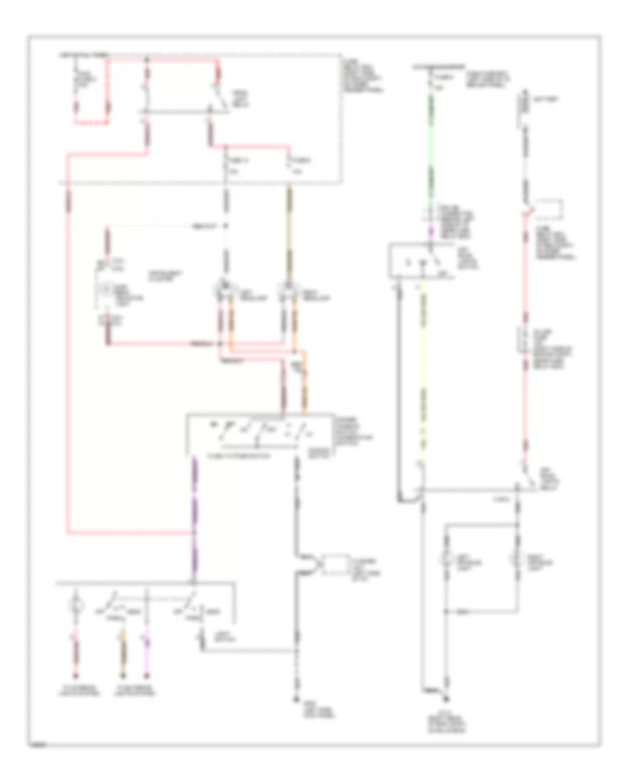
HEADLIGHTS
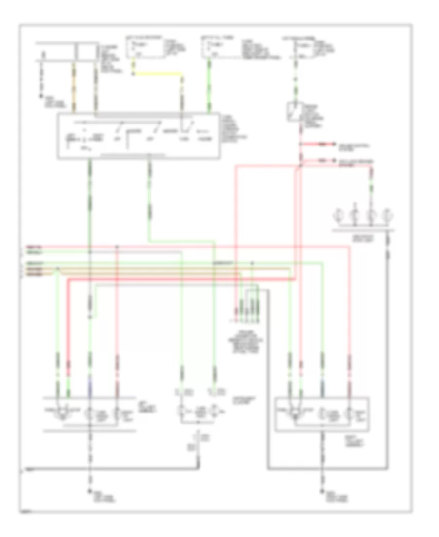
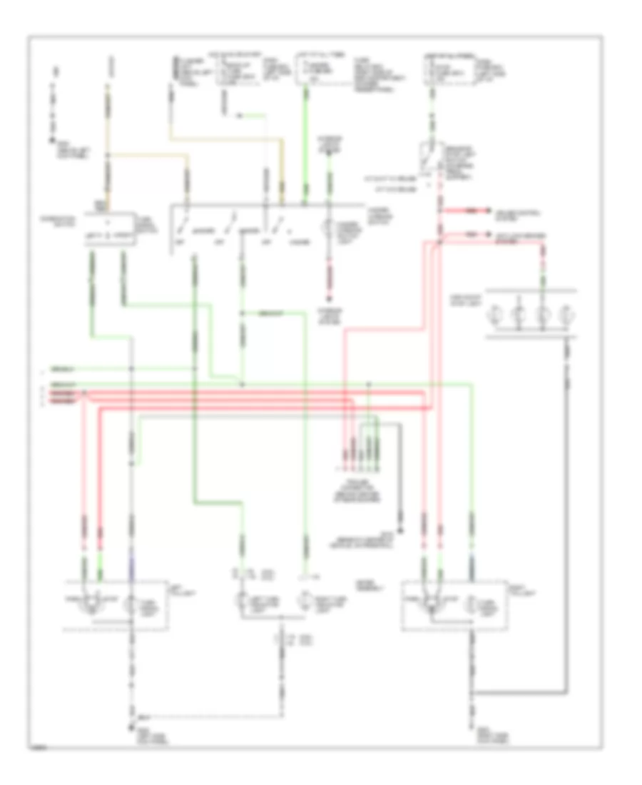
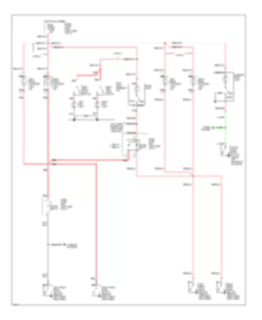
Headlight Wiring Diagram, Early Production for Isuzu Rodeo S 1995
List of elements for Headlight Wiring Diagram, Early Production for Isuzu Rodeo S 1995:
- (2.6l)
- (2.6l) a7 a4
- (3.2l)
- (right rear of eng compt, on bulkhead)
- 10a
- 15a
- 3 or 5
- Battery
- Dash fuse box (left side of i/p, behind panel)
- Dimmer/ passing switch (combination switch)
- Dimming switch
- Flash to pass switch
- Flasher unit (left side of i/p)
- Fuse 10
- Fuse 6
- Fuse 9
- Fuse/ relay box (right side of eng compt, on inner fender panel)
- G114
- G200 (left side kick panel)
- Head
- Head- light relay
- High beam indicator light
- Hot at all times
- Hot in on or start
- In-line fuse 15a (right side of engine compt, near fuse/ relay box)
- Instrument cluster
- Left headlamp
- Left off-road light
- Light switch
- Main fuse 2 30a
- Off
- Off- road lights relay
- Off- road lights switch
- Park
- Red
- Right headlamp
- Right off-road light
- Splice connector (behind left side of i/p, near fuse relay box)
- To exterior lights system
- To interior lights system
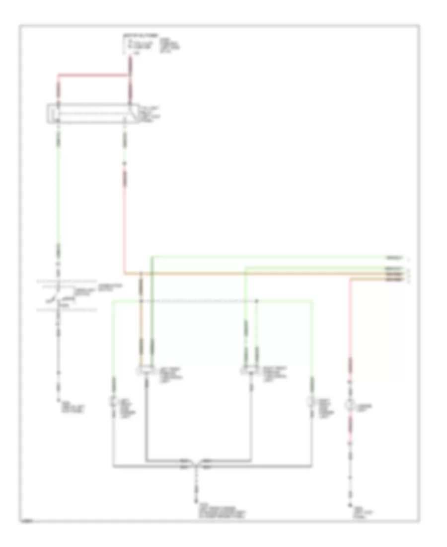
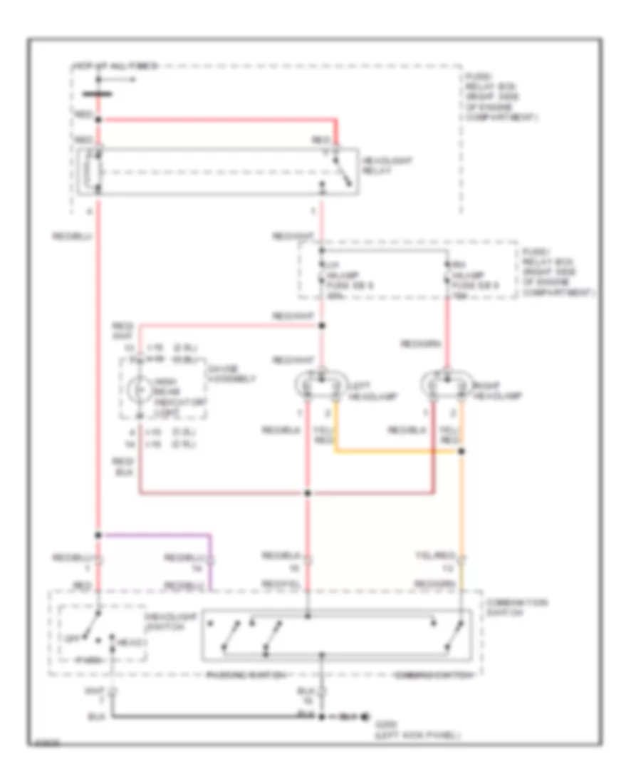
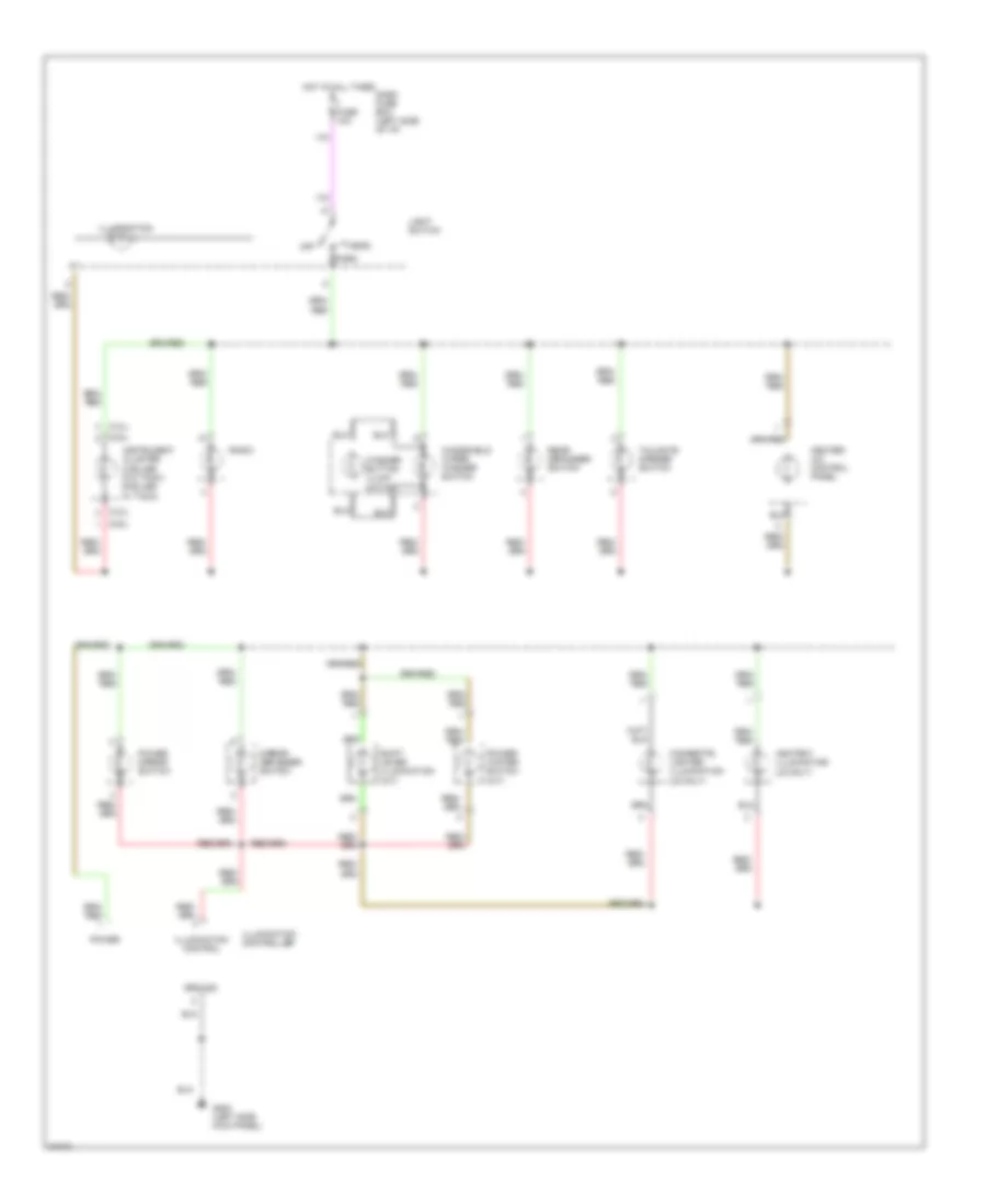
Headlight Wiring Diagram, Late Production for Isuzu Rodeo S 1995
List of elements for Headlight Wiring Diagram, Late Production for Isuzu Rodeo S 1995:
- (2.6l)
- (3.2l)
- Combination switch
- Dimming switch
- Fuse/ relay box (right side of engine compartment)
- G200 (left kick panel)
- Gauge assembly
- Head
- Headlight relay
- Headlight switch
- High beam indicator light
- Hot at all times
- I-15
- I-16
- Left headlamp
- Lh h/lamp fuse eb 8 10a
- Off
- Park
- Passing switch
- Red
- Rh h/lamp fuse eb 9 10a
- Right headlamp
HORN
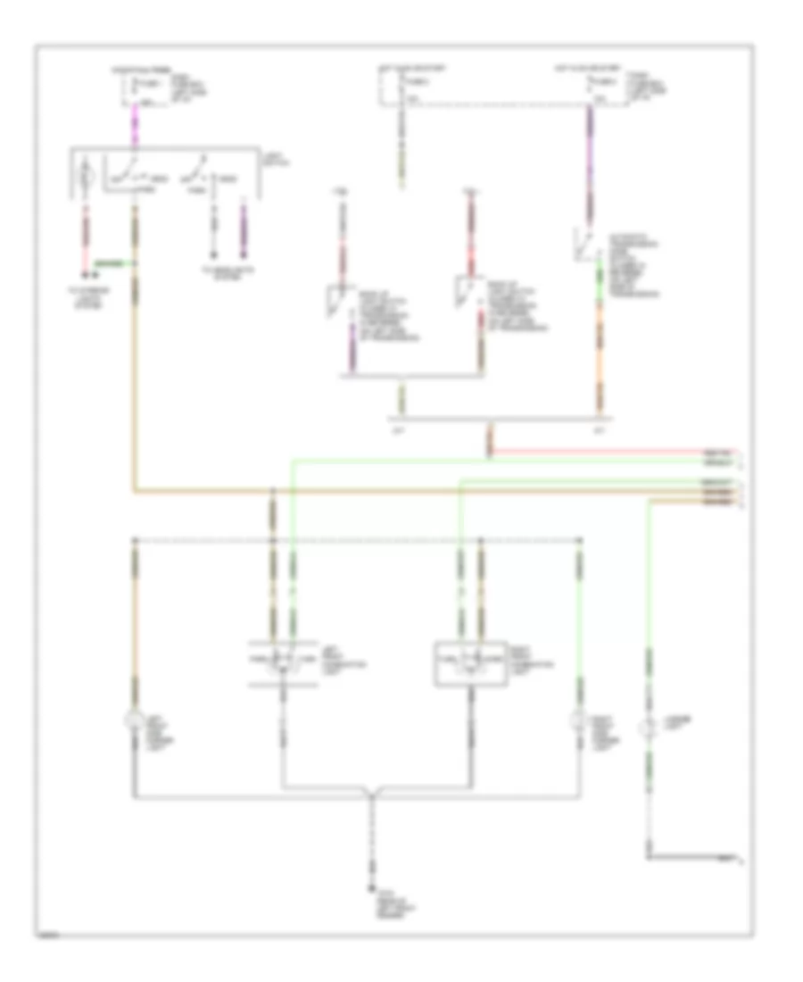
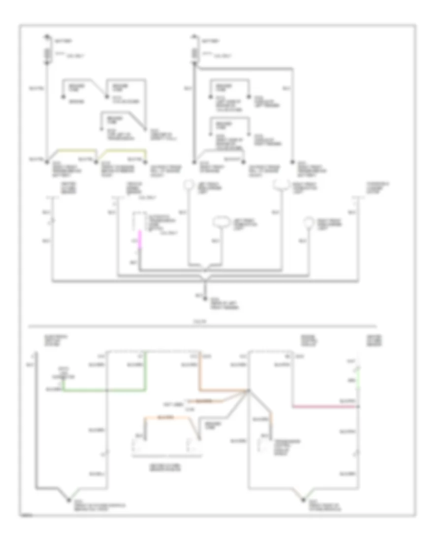
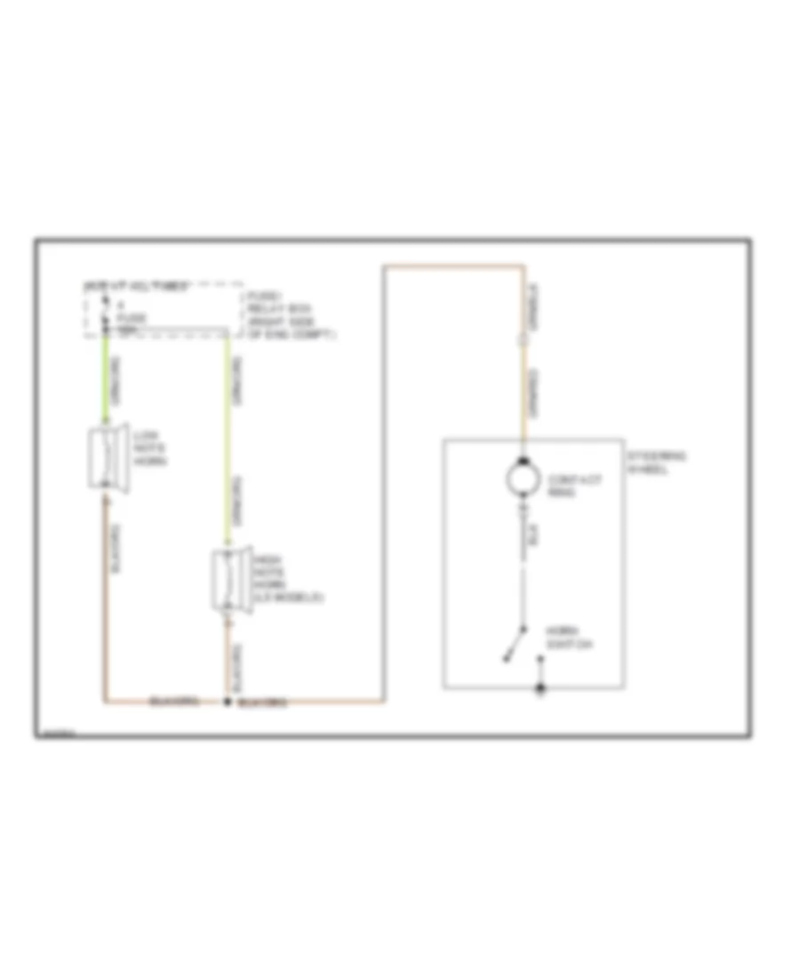
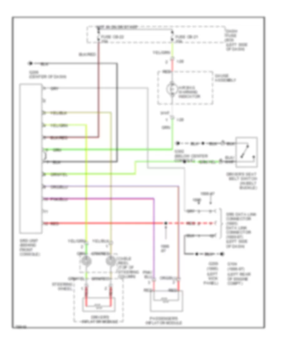
Horn Wiring Diagram, Early Production for Isuzu Rodeo S 1995
List of elements for Horn Wiring Diagram, Early Production for Isuzu Rodeo S 1995:
- Contact ring
- Fuse 10a
- Fuse/ relay box (right side of eng compt)
- High note horn (ls models)
- Horn switch
- Hot at all times
- Low note horn
- Steering wheel
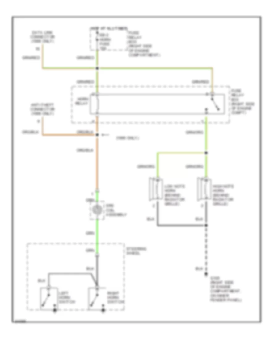
Horn Wiring Diagram, Late Production for Isuzu Rodeo S 1995
List of elements for Horn Wiring Diagram, Late Production for Isuzu Rodeo S 1995:
- (1996 only)
- Anti-theft connector (1996 only)
- Data link connector (1996 only)
- Eb-2 horn fuse 10a
- Fuse relay box (right side of engine compartment)
- Fuse relay box (right side of engine compt)
- G105 (right side of engine compartment, on inner fender panel)
- High note horn (behind radiator grille)
- Horn relay
- Hot at all times
- Left horn switch
- Low note horn (behind radiator grille)
- Right horn switch
- Srs coil assembly
- Steering wheel
INSTRUMENT CLUSTER
2.6L
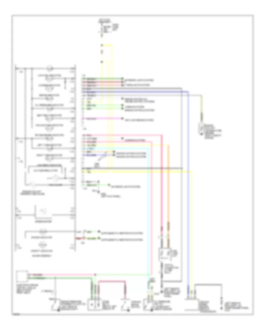
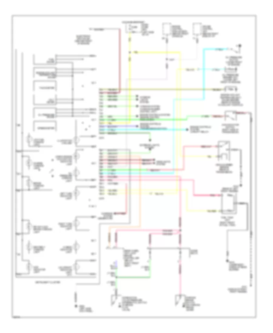
2.6L, Instrument Cluster Wiring Diagram, Early Production for Isuzu Rodeo S 1995
List of elements for 2.6L, Instrument Cluster Wiring Diagram, Early Production for Isuzu Rodeo S 1995:
- A10
- A11
- A12
- B10
- B11
- B12
- Brake warning light
- C211
- C274
- C275
- Charge warning light
- Charging system (generator)
- Check engine malfunction indicator lamp
- Combination valve pressure differential switch (in brake fluid valve)
- Dash fuse box
- Diode box d
- Engine control module (ecm) (left kick panel)
- Engine controls system (diode box a)
- Engine controls system (engine control module ecm)
- Engine coolant temperature (ect) gauge sender (right side of engine below intake manifold)
- Engine coolant temperature gauge
- Exterior lights system (combination switch)
- Fuel gauge
- Fuel tank unit (right front of fuel tank)
- Fuse 10a
- G200 (left side kick panel)
- G415 (under body, ahead of rear bumper)
- Headlights system
- Hi beam indicator light
- Hot in on or start
- Illumination (2 bulbs w/ tachometer) (9 bulbs w/o tachometer)
- Indicator cancel switch
- Instrument cluster
- Interior lights system
- Internal voltage regulator
- Left turn indicator light
- Low fuel warning light
- O2 sensor indicator light
- Oil pressure switch (lower front of engine)
- Oil pressure warning light
- Parking brake switch (on parking brake lever)
- Pnk
- Rear wheel anti-lock brake controller (below right front seat)
- Red
- Right turn indicator light
- Rr antilock brake warning light
- Seatbelt warning light
- Vehicle speed sensor
- Warning system (warning buzzer control unit)
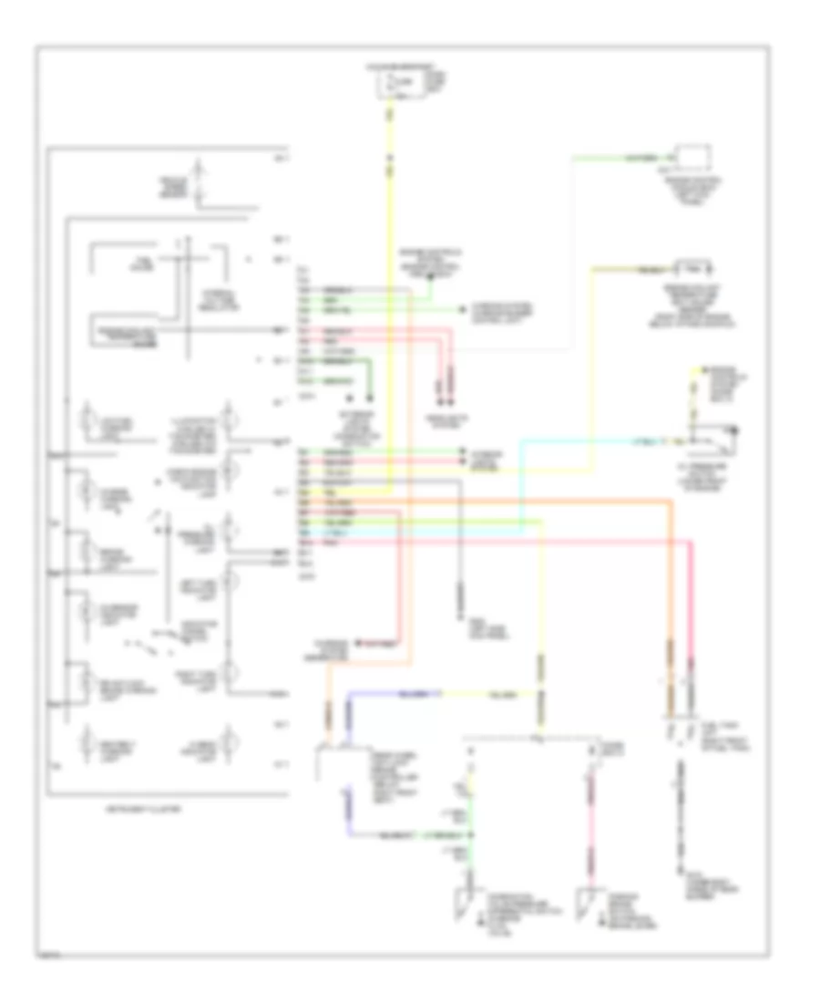
2.6L, Instrument Cluster Wiring Diagram, Late Production for Isuzu Rodeo S 1995
List of elements for 2.6L, Instrument Cluster Wiring Diagram, Late Production for Isuzu Rodeo S 1995:
- (left rear of eng compt, 0n inner fender panel) g104
- (left rear of eng compt, on inner fender panel)
- (not used)
- (pigtail connection in 1995 only)
- 1-15
- Air bag indicator
- Anti-lock brake system
- Brake indicator
- Brake pressure differential switch (left rear of engine compt)
- Charge indicator
- Charging system
- Dash fuse box
- Diode box d (below left side of i/p)
- Electronic brake control module (below right front seat)
- Engine controls & cruise control systems
- Engine controls system
- Engine coolant temperature gauge
- Engine coolant temperature sender (right side of engine)
- Exterior lights system
- Fuel gauge
- Fuel tank unit
- G104
- G200 (left kick panel)
- Gauge assembly
- Headlights system
- High beam indicator
- Hot in on or start
- I-16
- I-28
- Left turn indicator
- Low fuel indicator
- Malfunction indicator
- Meter cb-7 15a
- Oil pressure indicator
- Oil pressure switch (lower right side of engine)
- Only
- Parking brake switch
- Pnk
- Red
- Right turn indicator
- Rr abs brake indicator
- Seat belt indicator
- Speedometer
- Upshift indicator
- Vehicle speed sensor (rear of transmission)
- Voltage regulator
- Warning system
3.2L
3.2L, Instrument Cluster Wiring Diagram, Early Production for Isuzu Rodeo S 1995
List of elements for 3.2L, Instrument Cluster Wiring Diagram, Early Production for Isuzu Rodeo S 1995:
- 4wd indicator light
- 4wd indicator switch (right side of transmission)
- A10
- A11
- A12
- A13
- A14
- B10
- B11
- B12
- B13
- B14
- Brake warning light
- C274
- C275
- Charge warning light
- Charging system (generator)
- Check engine malfunction indicator lamp
- Combination valve pressure differential switch (in brake fluid valve)
- Cruise control unit (behind right side of i/p)
- Dash fuse box (left side of i/p)
- Diode box d
- Electronic ignition (ei) (center front of engine)
- Engine control module (ecm) (behind front console)
- Engine controls system (engine control module ecm)
- Engine controls system (transmission switch)
- Engine controls system (upshift relay)
- Engine coolant temperature gauge
- Engine coolant temperaure (ect) gauge sender (rear of engine in coolant manifold)
- Exterior lights system
- Fuel gauge
- Fuel tank unit (right front of fuel tank)
- Fuse 10a
- G101 (middle of right front fender)
- G104 (rear of left front fender)
- G200 (left side kick panel)
- G415 (under body, ahead of rear bumper)
- Headlights system
- Hi beam indicator light
- Hot in on or start
- Illumination (4 bulbs)
- Instrument cluster
- Interior lights system
- Left turn indicator light
- Low fuel warning light
- Oil pressure gauge
- Oil pressure sender unit (lower left front of engine)
- Oil pressure switch (lower front of engine)
- Oil pressure warning light
- Parking brake switch (on parking brake lever)
- Pnk
- Rear wheel anti-lock brake controller (below right front seat)
- Right turn indicator light
- Rr antilock brake warning light
- Seatbelt warning light
- Speedometer
- Tachometer
- U/s upshift indicator light (m/t)
- Vehicle speed sensor (rear of transmission)
- Volt meter
- Warning system (warning buzzer control unit)
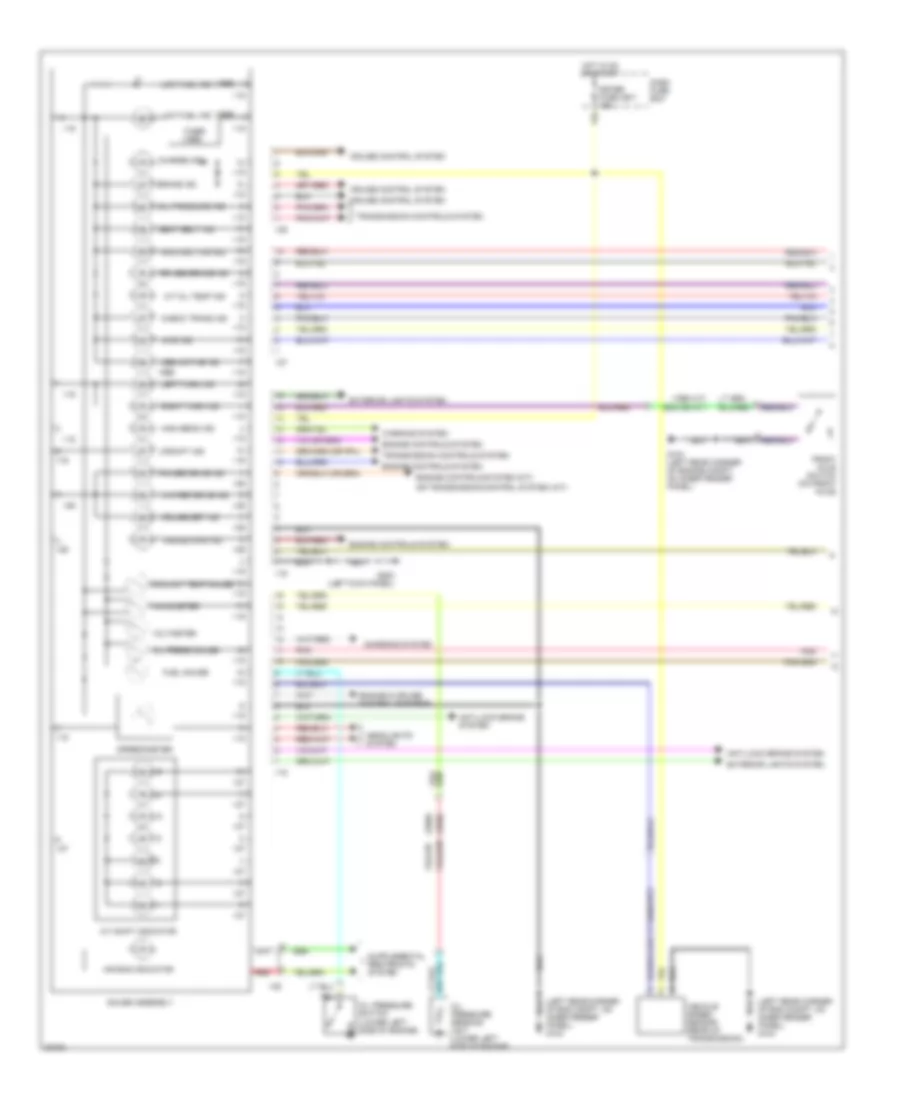
3.2L, Instrument Cluster Wiring Diagram, Late Production (1 of 2) for Isuzu Rodeo S 1995
List of elements for 3.2L, Instrument Cluster Wiring Diagram, Late Production (1 of 2) for Isuzu Rodeo S 1995:
- (1995 a/t)
- (1995)
- (1996)
- (exc 95 a/t)
- (left rear corner of eng compt, on inner fender panel) g104
- 4wd ind
- A/t oil temp ind
- A/t shift indicator
- Abs active ind
- Air bag indicator
- Anti-lock brake system
- Brake ind
- Charge ind
- Charging system
- Check trans ind
- Coolant temp gauge
- Cruise control system
- Cruise main ind
- Cruise set ind
- Dash fuse box
- Engine & cruise control systems
- Engine controls system
- Engine controls system (m/t)
- Exterior lights system
- Front axle switch (on front axle)
- Fuel gauge
- G104 (left rear corner of engine compt, on inner fender panel)
- G200 (left kick panel)
- Gauge assembly
- Headlights system
- High beam ind
- Hot in on or start
- I-15
- I-16
- I-26
- I-27
- I-28
- Left turn ind
- Low fuel ind
- Malfunction ind
- Meter fuse cb-7 15a
- Oil press gauge
- Oil pressure ind
- Oil pressure sending unit (lower left side of engine)
- Oil pressure switch (lower left side of engine)
- Or transmission control system (a/t)
- Pnk
- Power drive ind
- Red
- Right turn ind
- Rr abs brake ind
- Seat belt ind
- Speedometer
- Tachometer
- Timer (1995)
- Transmission controls system
- Upshift ind
- Vehicle speed sensor (rear of transmission)
- Voltmeter
- Warning system
- Winter drive ind
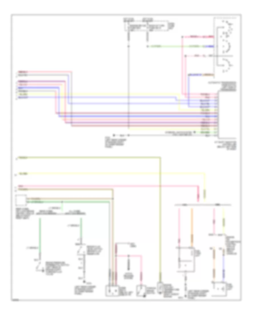
3.2L, Instrument Cluster Wiring Diagram, Late Production (2 of 2) for Isuzu Rodeo S 1995
List of elements for 3.2L, Instrument Cluster Wiring Diagram, Late Production (2 of 2) for Isuzu Rodeo S 1995:
- (left rear corner of engine compt, on inner fender panel)
- (not used)
- A/t shift indicator controller (below left side of dash)
- All wheel anti-lock brakes
- Automatic transmission mode switch (left side of transmission)
- B15
- Back-up turn fuse cb-15 15a
- Brake fluid level switch (brake fluid reservoir)
- Brake pressure differential switch (left rear of engine compt, in brake fluid valve)
- C13
- Dash fuse box
- Diode box d (below left side of i/p)
- Engine coolant temperature sender (right side of engine)
- Engine device fuse cb-3 15a
- Engine or powertrain control module (behind front console)
- Fuel tank unit
- G104
- G104 (left rear corner of engine compt, on inner fender panel)
- Hatch release system
- Hot in on or start
- Interior lights system (taillight relay)
- Parking brake switch
- Pnk
- Rear wheel anti-lock brake control module (below right front seat)
- Rear wheel anti-lock brakes
INTERIOR LIGHTS
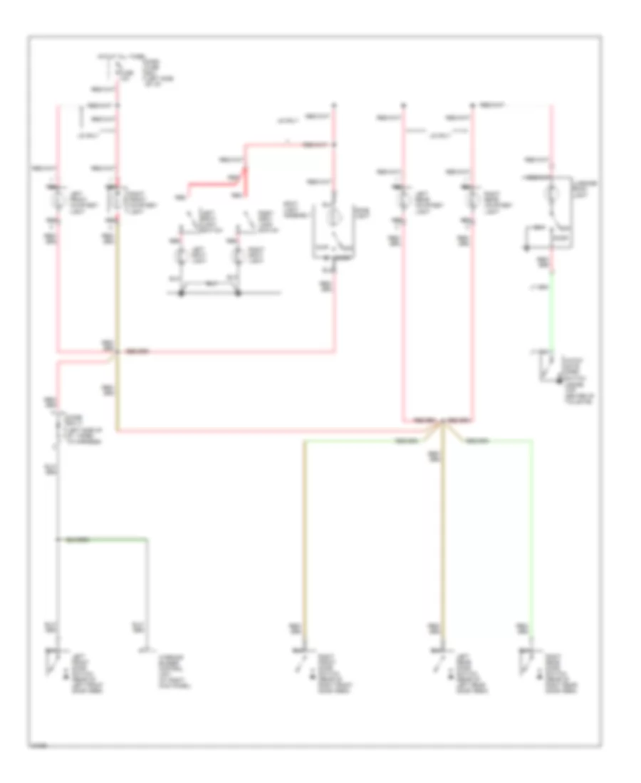
Courtesy Lamps Wiring Diagram, Early Production for Isuzu Rodeo S 1995
List of elements for Courtesy Lamps Wiring Diagram, Early Production for Isuzu Rodeo S 1995:
- (inside top center of tailgate)
- (left side of i/p, taped to harness)
- Dash fuse box (left side of i/p)
- Diode box c
- Dome light
- Door
- Fuse 10a
- Hatch gate open switch
- Hot at all times
- Left front courtesy light
- Left front door switch (rear of left front door area)
- Left rear courtesy light
- Left rear door switch (rear of left rear door area)
- Left spot light
- Left spot light switch
- Ls only
- Luggage room light
- Off
- Red
- Right front courtesy light
- Right front door switch (rear of right front door area)
- Right rear courtesy light
- Right rear door switch (rear of right rear door area)
- Right spot light
- Right spot light switch
- Spot light assembly
- Warning buzzer control unit (at right kick panel)
Courtesy Lamps Wiring Diagram, Late Production for Isuzu Rodeo S 1995
List of elements for Courtesy Lamps Wiring Diagram, Late Production for Isuzu Rodeo S 1995:
- (inside top center of tailgate)
- * 1995 m.y. ** 1996 m.y.
- *1 **3
- *2 **1
- *3 **2
- Anti-theft connector (1996 model year only)
- Cb9 room fuse 10a
- Dash fuse box (left side of i/p)
- Diode box f
- Diode box g
- Dome light
- Door
- Hatch gate open switch
- Hot at all times
- Left front courtesy light (ls)
- Left front door switch (rear of left front door area)
- Left map light
- Left rear courtesy light (ls)
- Left rear door switch (rear of left rear door area)
- Left spot light switch
- Ls only
- Luggage room light
- Off
- Red
- Right front courtesy light (ls)
- Right front door switch (rear of right front door area)
- Right map light
- Right rear courtesy light (ls)
- Right rear door switch (rear of right rear door area)
- Right spot light switch
- Spot light assembly (ls)
- Warning systems
- Wiper/ washer
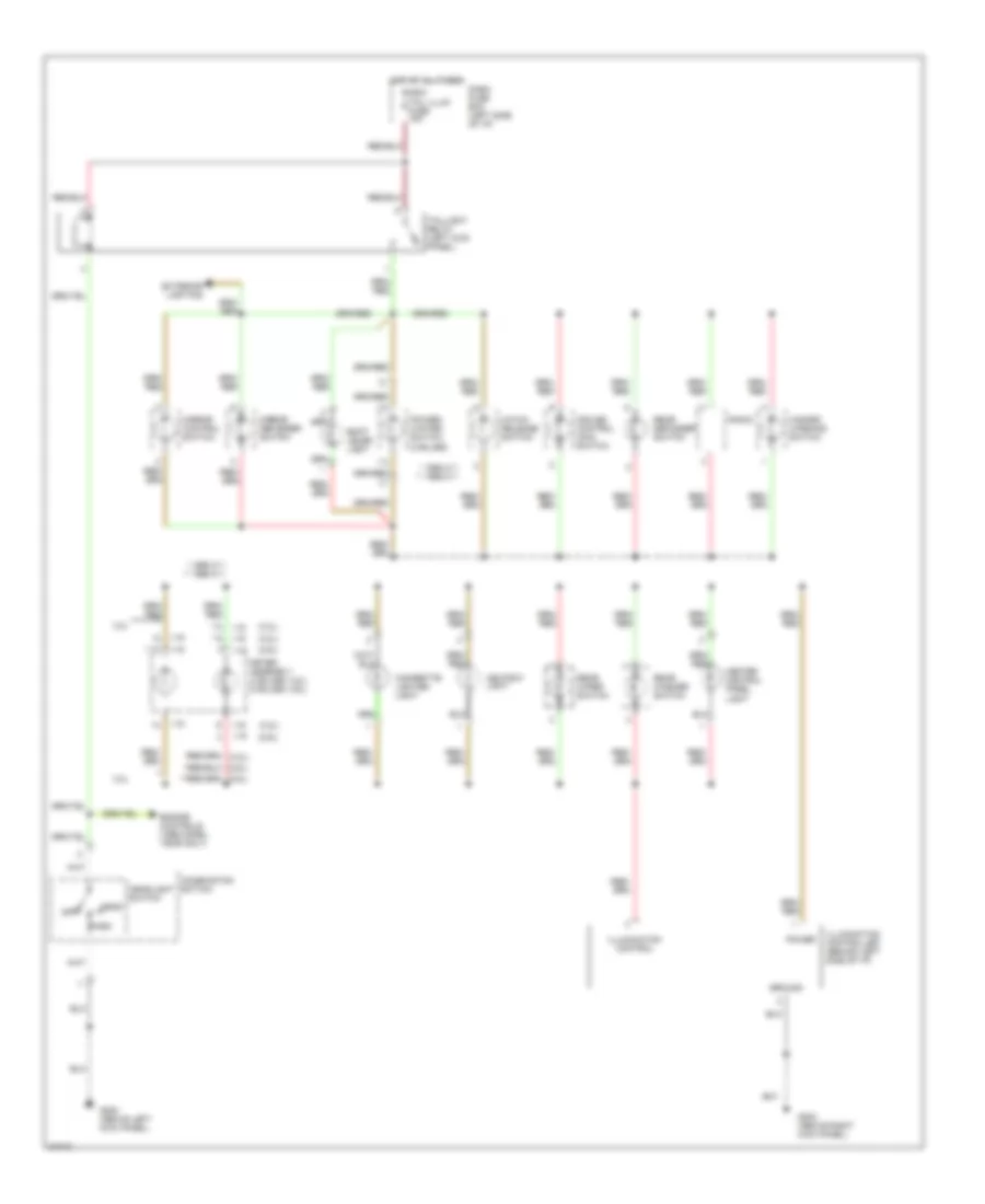
Instrument Illumination Wiring Diagram, Early Production for Isuzu Rodeo S 1995
List of elements for Instrument Illumination Wiring Diagram, Early Production for Isuzu Rodeo S 1995:
- (2 bulbs w/o tach) (9 bulbs w/ tach)
- (2.6l)
- (3.2l)
- (ls only)
- Ashtray illumination
- Cigarette lighter illumination (ls only)
- Dash fuse box (left side of i/p)
- Fuse 10a
- G200 (left side kick panel)
- Ground
- Head
- Heater- a/c control panel
- Hot at all times
- Illumination
- Illumination control
- Illumination controller
- Instrument cluster
- Light switch
- Mirror defogger switch
- Off
- Park
- Power
- Power mirror switch
- Power/ winter switch (a/t)
- Radio
- Rear defogger switch
- Shift lever illumination (a/t)
- Tailgate opener switch
- Washer button illumi- nation
- Windshield wiper/ washer switch
Instrument Illumination Wiring Diagram, Late Production for Isuzu Rodeo S 1995
List of elements for Instrument Illumination Wiring Diagram, Late Production for Isuzu Rodeo S 1995:
- (2.6l)
- (3.2l)
- * 1995 m.y. ** 1996 m.y.
- **13
- **2
- **3
- **5
- *13
- 3.2l
- Ashtray light
- Cb-5 tail illum fuse 15a
- Cigarette lighter light
- Combination swtich
- Cruise control main switch
- Dash fuse box (left side of i/p)
- Engine controls (1996 model year only)
- Exterior lighting
- G200 (above left kick panel)
- G203 (above right kick panel)
- Ground
- Hatch release switch
- Hazard warning switch
- Head
- Headlight switch
- Heater control panel light
- Hot at all times
- I-15
- I-16
- Illumination control
- Illumination controller (behind left side of i/p)
- Meter assembly (3 bulbs- 3.2l) (2 bulbs- 2.6l)
- Mirror control switch
- Mirror defogger switch
- Off
- Park
- Power
- Power/ winter switch (2 bulbs)
- Radio
- Rear defogger switch
- Rear washer switch
- Rear wiper switch
- Shift lever light
- Taillight relay (left kick panel)
POWER DISTRIBUTION
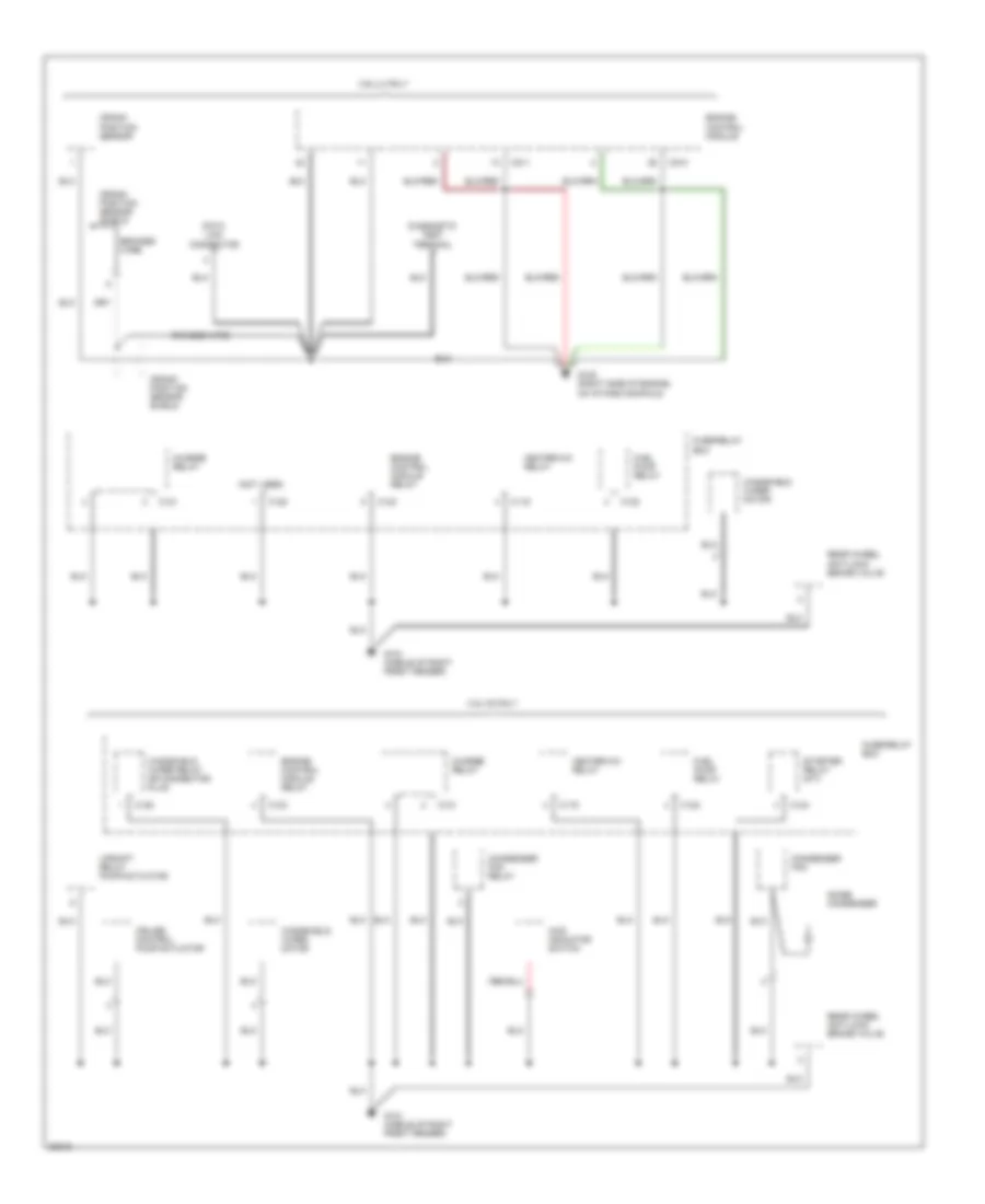
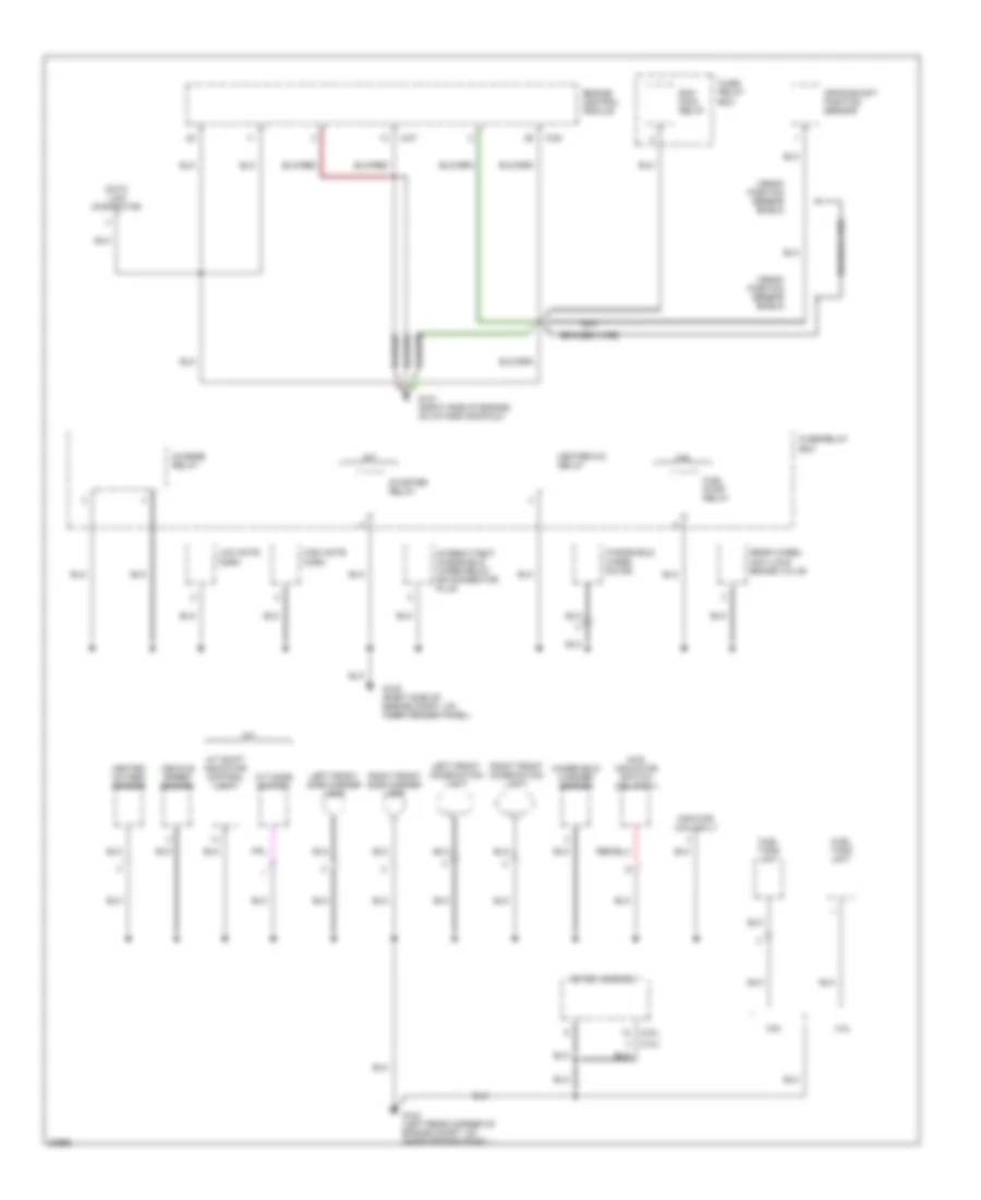
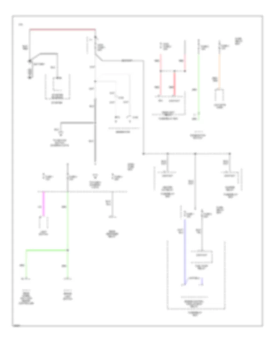
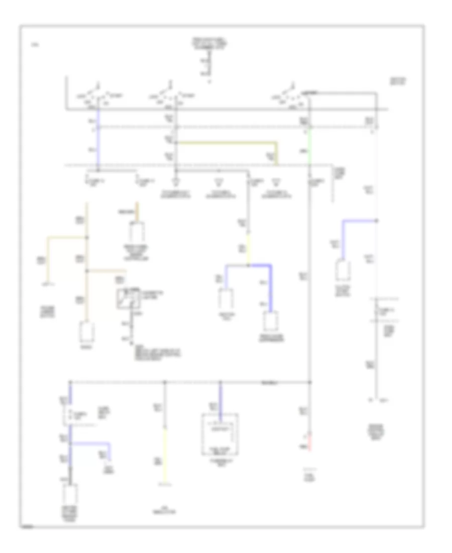
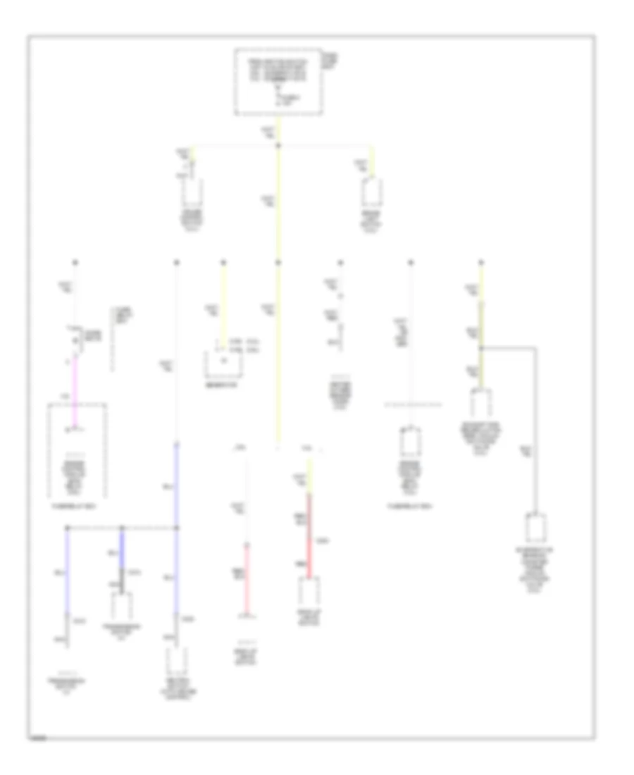
Power Distribution Wiring Diagram, Early Production (1 of 6) for Isuzu Rodeo S 1995
List of elements for Power Distribution Wiring Diagram, Early Production (1 of 6) for Isuzu Rodeo S 1995:
- 2.6l
- Battery
- Brake light switch
- C105
- C106
- Charge relay
- Coil
- Combination switch
- Contact
- Dash fuse box
- Engine control module (ecm) relay
- Fuel pump relay
- Fuse 1 10a
- Fuse 1 15a
- Fuse 2 10a
- Fuse 2 20a
- Fuse 3 15a
- Fuse 4 10a
- Fuse 4 25a
- Fuse/ relay box
- Fuse/relay box
- Generator
- Headlight relay
- Heater a/c relay
- Light switch
- Low note horn
- Main fuse 1 60a
- Main fuse 2 30a
- Rear defogger relay
- Rear wheel anti-lock brake controller
- Red
- Starter
- Starter solenoid
- To fuse 3 (diagram 4 of 6)
- To ignition switch (diagram 2 of 6)
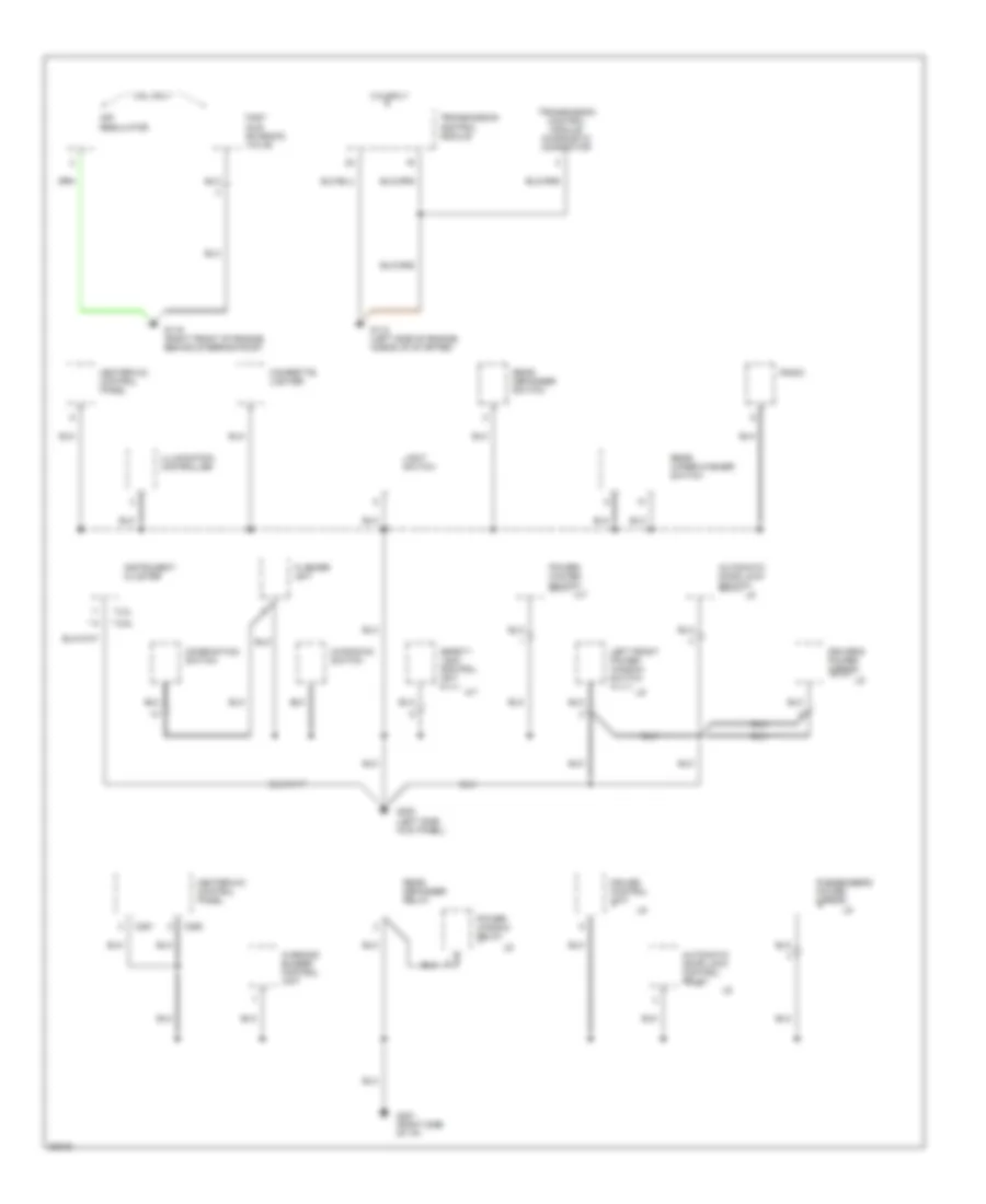
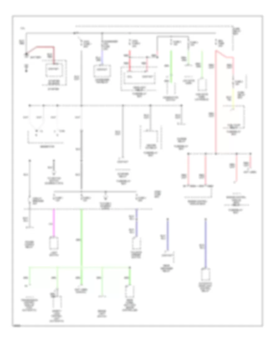
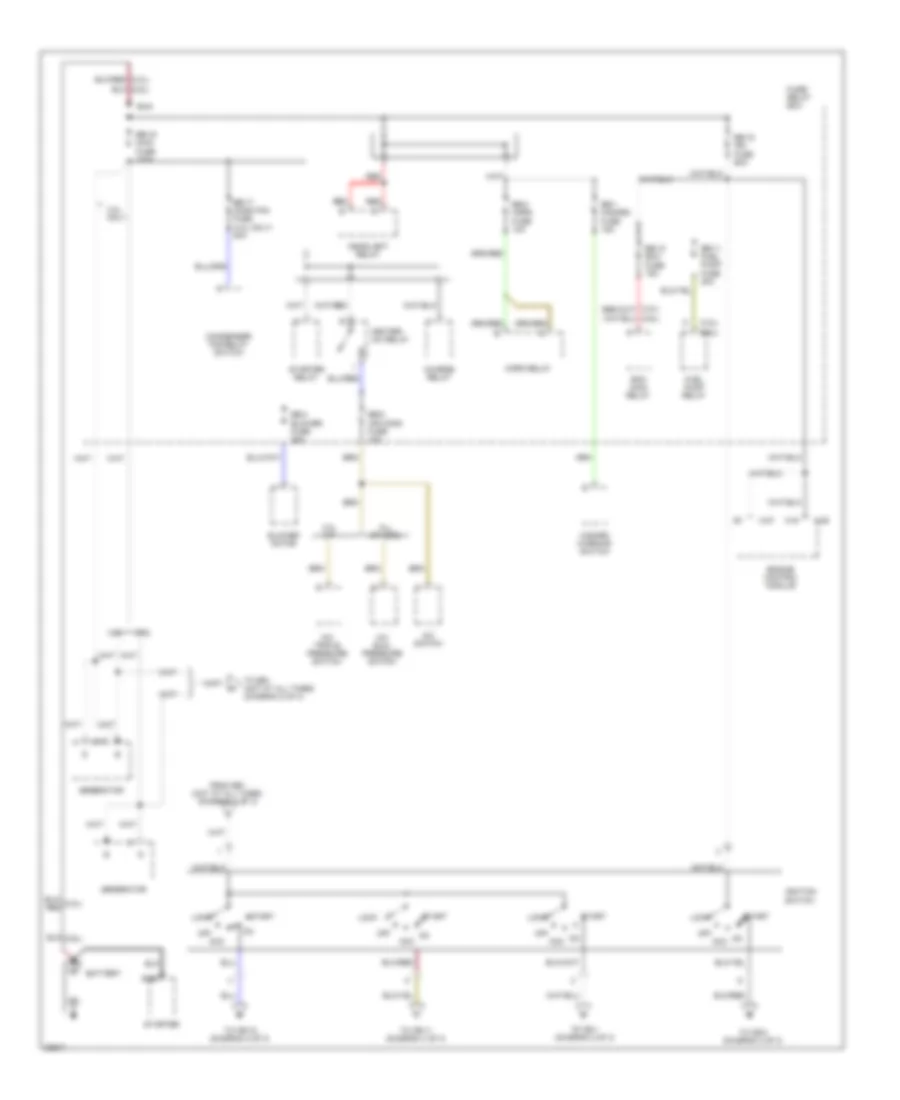
Power Distribution Wiring Diagram, Early Production (2 of 6) for Isuzu Rodeo S 1995
List of elements for Power Distribution Wiring Diagram, Early Production (2 of 6) for Isuzu Rodeo S 1995:
- (not used)
- 2.6l
- Acc
- Air regulator
- C211
- C283
- C284
- Cigarette lighter
- Clutch start switch
- Contact
- Dash fuse box
- Engine control module (ecm)
- From main fuse 1 (hot at all times) (diagram 1 of 6)
- Fuel pump
- Fuel pump relay
- Fuse 12 10a
- Fuse 12 15a
- Fuse 13 20a
- Fuse 5 20a
- Fuse 6 10a
- Fuse 9 15a
- Fuse/ relay box
- Fuse/relay box
- G200 (below left side of i/p, behind engine control module (ecm))
- Heated oxygen sensor (ho2s)
- Ignition coil
- Ignition switch
- Lock
- Nca
- Off
- On acc
- Power mirror switch
- Radio
- Radio noise suppressor
- Rear wheel anti-lock brake controller
- Red
- Start
- To fuse 10 (diagram 5 of 6)
- To fuse 8 (diagram 6 of 6)
- To fuses 6 & 7 (diagram 5 of 6)
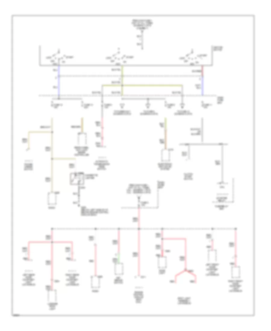
Power Distribution Wiring Diagram, Early Production (3 of 6) for Isuzu Rodeo S 1995
List of elements for Power Distribution Wiring Diagram, Early Production (3 of 6) for Isuzu Rodeo S 1995:
- (not used)
- (not used) (manual)
- 3.2l
- Automatic door lock control relay
- Battery
- Brake light switch
- C150
- C16
- C218
- C219
- Charge relay
- Circuit breaker 30a
- Coil
- Combination switch
- Condenser fan fuse 30a
- Condenser fan relay
- Contact
- Dash fuse box
- Ecm fuse 30a
- Engine control module (ecm)
- Engine control module (ecm) relay
- Fuel pump relay
- Fuse 1 10a
- Fuse 2 10a
- Fuse 2 15a
- Fuse 3 15a
- Fuse 4 10a
- Fuse 4 25a
- Fuse/ relay box
- Fuse/relay box
- Generator
- Headlight relay
- Heater a/c relay
- High note horn (ls models)
- Light switch
- Low note horn
- Main fuse 1 60a
- Main fuse 2 30a
- Power window relay
- Rear defogger relay
- Rear wheel anti-lock brake controller
- Red
- Safety lock control unit (automatic)
- Starter
- Starter relay
- Starter solenoid
- Tailgate opener switch
- To fuse 3 (diagram 4 of 6)
- To ignition switch (diagram 4 of 6)
- Transmission control module (tcm) (automatic)
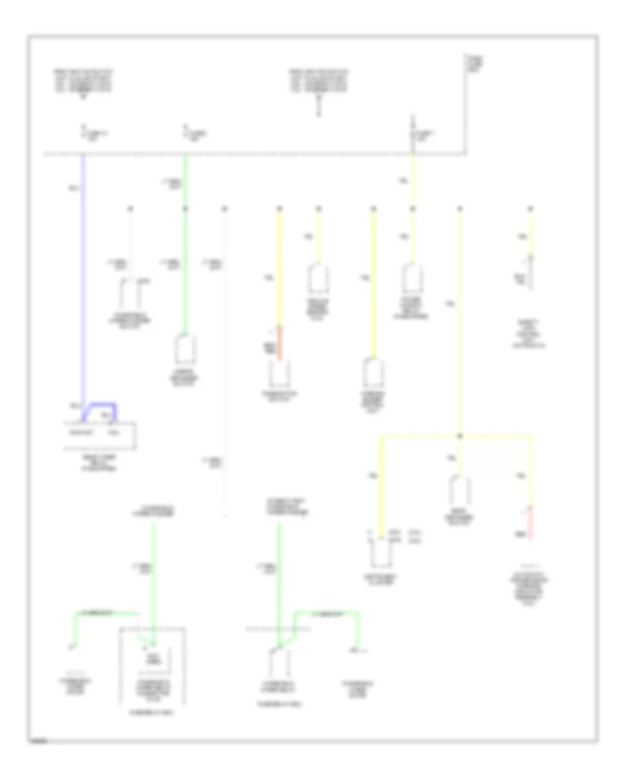
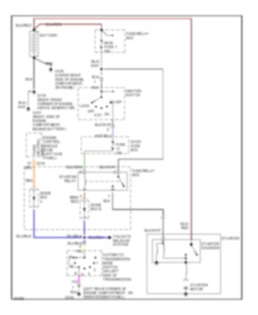
Power Distribution Wiring Diagram, Early Production (4 of 6) for Isuzu Rodeo S 1995
List of elements for Power Distribution Wiring Diagram, Early Production (4 of 6) for Isuzu Rodeo S 1995:
- A/t
- Acc
- Automatic transmission mode switch
- C176
- C211
- C283
- C284
- C286
- C900
- C902
- C904
- Cigarette lighter
- Clutch start switch
- Coil
- Dash fuse box
- Dome light
- Electronic ignition (ei) system
- Engine control module (ecm) (2.6l)
- From main fuse 1 (hot at all times) (diagram 3 of 6) (3.2l only)
- From main fuse 1 (hot at all times) 2.6l - (diagram 1 of 6) 3.2l - (diagram 3 of 6)
- Fuse 11 10a
- Fuse 12 15a
- Fuse 13 20a
- Fuse 3 10a
- Fuse 5 10a
- Fuse 9 15a
- Fuse/relay box
- G200 (below left side of i/p, behind engine control module (ecm))
- Ignition switch
- Key remind switch
- Left front door courtesy light (ls models)
- Left rear door courtesy light (ls models)
- Lock
- Luggage room light
- M/t
- Off
- On acc
- Power mirror switch
- Radio
- Rear wheel anti-lock brake controller
- Red
- Right front door courtesy light (ls models)
- Right rear door courtesy light (ls models)
- Spot light assembly (ls models)
- Start
- Starter relay
- To fuse 10 (diagram 5 of 6)
- To fuse 8 (diagram 6 of 6)
- To fuses 6 & 7 (diagram 5 of 6)
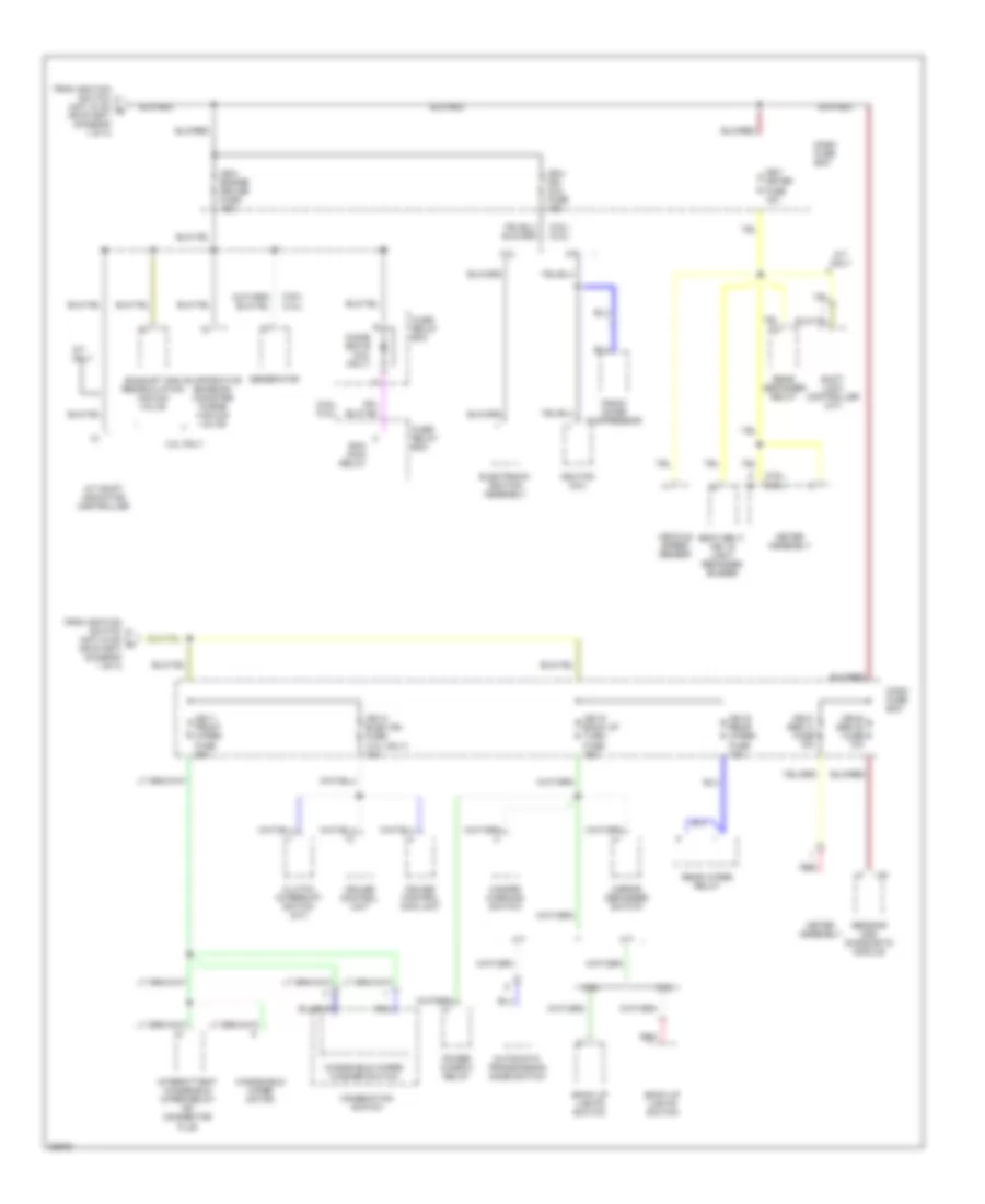
Power Distribution Wiring Diagram, Early Production (5 of 6) for Isuzu Rodeo S 1995
List of elements for Power Distribution Wiring Diagram, Early Production (5 of 6) for Isuzu Rodeo S 1995:
- (2.6l)
- (3.2l)
- (not used)
- Automatic transmission warning/ indicator assembly (3.2l)
- C274
- C275
- C276
- Coil
- Combination switch
- Contact
- Dash fuse box
- From ignition switch (hot in on or start) 2.6l - (diagram 2 of 6) 3.2l - (diagram 4 of 6)
- Fuse 10 10a
- Fuse 6 15a
- Fuse 7 10a
- Fuse/relay box
- Instrument cluster
- Intermittent windshield wiper/washer
- Mirror defogger switch
- Power window relay (if equipped)
- Rear defogger switch
- Rear wiper relay (if equipped)
- Red
- Safety lock control unit (automatic)
- Vehicle speed sensor (3.2l)
- Warning buzzer control unit
- Windshield wiper motor
- Windshield wiper relay
- Windshield wiper relay connector plug
- Windshield wiper/washer
- Windshield wiper/washer switch
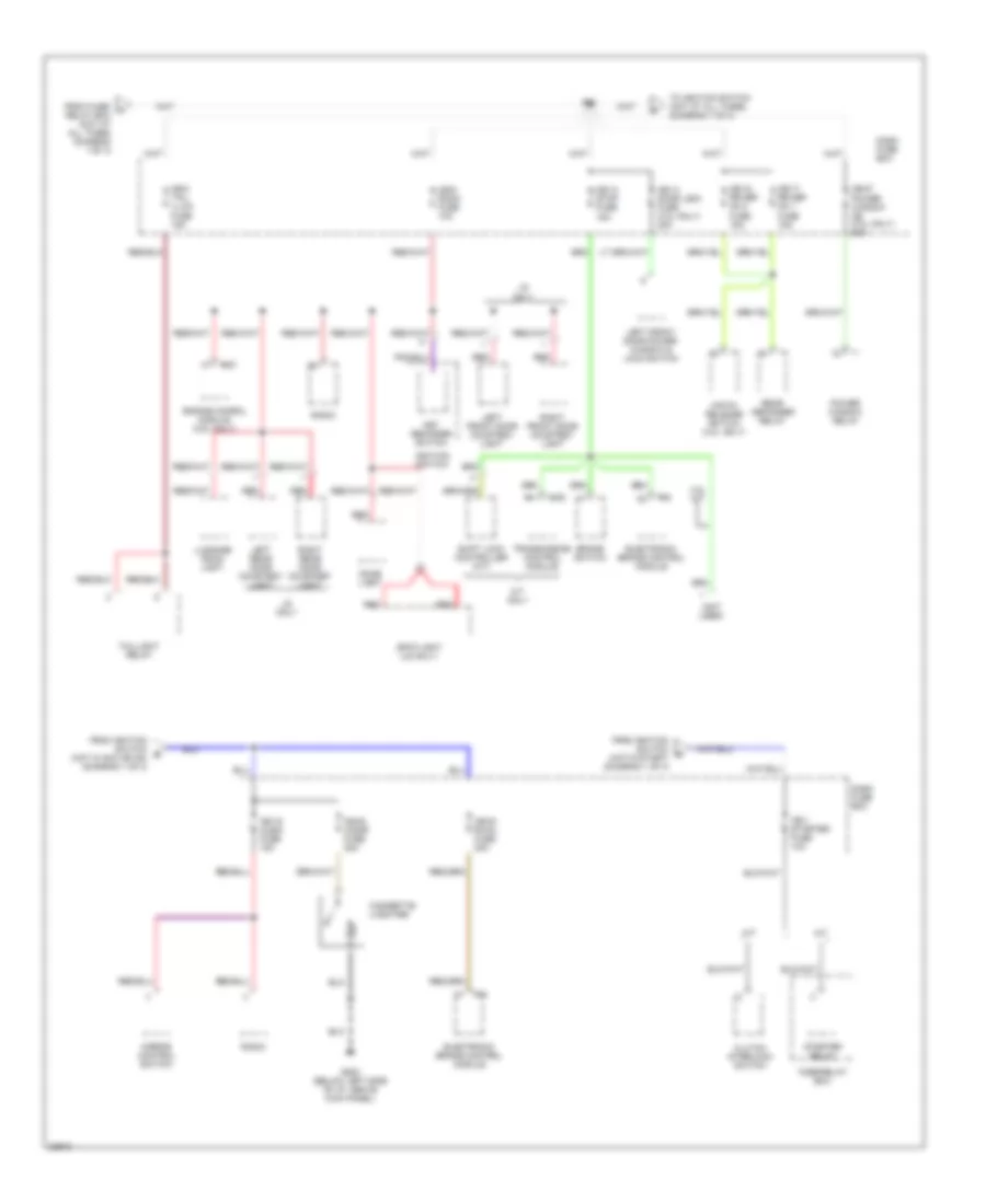
Power Distribution Wiring Diagram, Early Production (6 of 6) for Isuzu Rodeo S 1995
List of elements for Power Distribution Wiring Diagram, Early Production (6 of 6) for Isuzu Rodeo S 1995:
- (2.6l)
- (3.2l)
- 2.6l
- 3.2l
- Back up lights switch
- Brake light switch (3.2l)
- C106
- C150
- C312
- C313
- C332
- C333
- Cruise control switch (3.2l)
- Dash fuse box
- Diode box b
- Engine control module (ecm) relay (2.6l)
- Engine control module (ecm) relay (3.2l)
- Evaporative emission canister purge vacuum switching valve (3.2l)
- Exhaust gas recirculation (egr) vacuum switching valve (3.2l)
- From ignition switch (hot in on or start) 2.6l - (diagram 2 of 6) 3.2l - (diagram 4 of 6)
- Fuse 8 10a
- Fuse/ relay box
- Fuse/relay box
- Generator
- Heated oxygen sensor (ho2s) (3.2l)
- Nca
- Neutral switch (with cruise control)
- Red
- Transmission switch 1-2
- Transmission switch 3-4
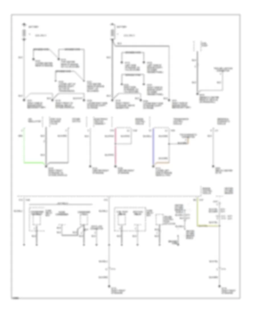
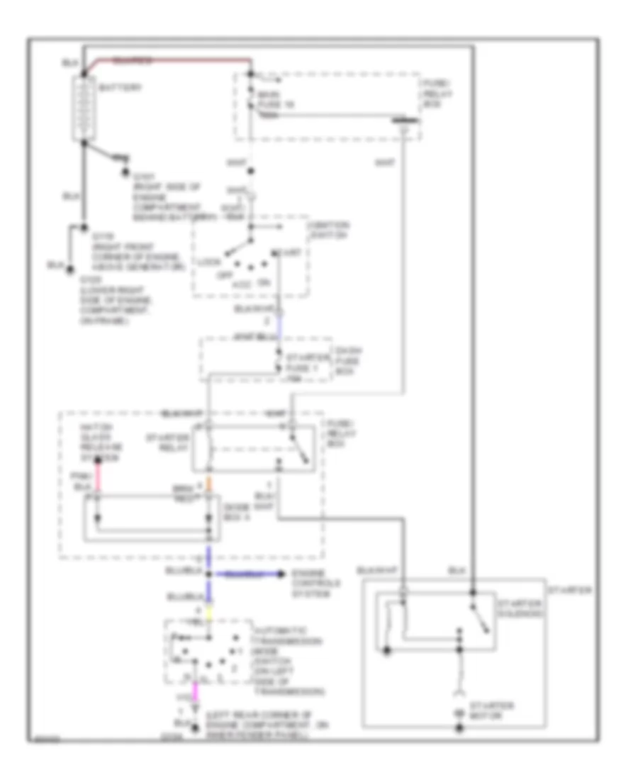
Power Distribution Wiring Diagram, Late Production (1 of 3) for Isuzu Rodeo S 1995
List of elements for Power Distribution Wiring Diagram, Late Production (1 of 3) for Isuzu Rodeo S 1995:
- (2.6l)
- (3.2l)
- 2.6l
- 3.2l
- 3.2l a/t
- 3.2l only
- A-27
- A-28
- A/c dual pressure switch
- A/c switch
- A/c triple pressure switch
- Acc
- All others
- Battery
- Blower motor
- C16
- Charge relay
- Condenser fan relay switch
- E-25
- E-46
- Eb-1 hazard fuse 15a
- Eb-11 fuel pump fuse 20a
- Eb-12 ecm fuse 15a
- Eb-15 ign fuse 60a
- Eb-16 main fuse 100a
- Eb-17 cond fan fuse (3.2l only) 30a
- Eb-2 horn fuse 10a
- Eb-4 blower fuse 20a
- Eb-5 air cond fuse 10a
- Ecm main relay
- Engine control module
- From sb1 (hot at all times) (diagram 2 of 3)
- Fuel pump relay
- Fuse/ relay box
- Generator
- Hazard warning switch
- Headlight relay
- Heater- a/c relay
- Horn relay
- Ignition switch
- Lock
- Off
- Red
- Start
- Starter
- Starter relay
- To cb-1 (diagram 2 of 3)
- To cb-11 (diagram 3 of 3)
- To cb-19 (diagram 2 of 3)
- To cb-3 (diagram 3 of 3)
- To sb1 (hot at all times) (diagram 2 of 3)
Power Distribution Wiring Diagram, Late Production (2 of 3) for Isuzu Rodeo S 1995
List of elements for Power Distribution Wiring Diagram, Late Production (2 of 3) for Isuzu Rodeo S 1995:
- (not used)
- 3.2l m/t
- A-27
- A-63
- A/t
- A/t only
- Brake switch
- Cb-1 starter fuse 10a
- Cb-13 stop fuse 15a
- Cb-14 door lock fuse (3.2l only) 20a
- Cb-17 rr def no 1 fuse 15a
- Cb-18 rr def no 2 fuse 15a
- Cb-19 audio fuse 15a
- Cb-20 cigar fuse 20a
- Cb-23 rwal fuse 20a
- Cb-27 power window cb (3.2l only) 30a
- Cb-5 tail illum fuse 15a
- Cb-9 room fuse 10a
- Cigarette lioghter
- Clutch interlock switch
- Dash fuse box
- Dome light
- Electronic brake control module
- Engine conrol module (2.6l only)
- From fuse/ a relay box (hot at all times) (diagram 1 of 3)
- From ignition switch b (hot in acc or on) (diagram 1 of 3)
- From ignition switch d (hot in start) (diagram 1 of 3)
- Fuse/relay box
- G200 (below left side of i/p, above kick panel)
- Hatch release switch (3.2l only)
- Ignition switch
- Key reminder switch
- Left front door courtesy light
- Left front door power window & lock switch
- Left rear door courtesy light
- Ls only
- Luggage room light
- M/t
- Mirror control switch
- Only
- Power window relay
- R-6
- Radio
- Rear defogger relay
- Red
- Right front door courtesy light
- Right rear door courtesy light
- Sb1
- Shift lock controller (a/t)
- Spotlight (ls only)
- Starter relay
- Taillight relay
- To ignition switch (hot at all times) (diagram 1 of 3)
- Transmission control module
Power Distribution Wiring Diagram, Late Production (3 of 3) for Isuzu Rodeo S 1995
List of elements for Power Distribution Wiring Diagram, Late Production (3 of 3) for Isuzu Rodeo S 1995:
- (2.6l) (3.2l)
- 2.6l
- 3.2l
- 3.2l only
- A/t
- A/t only
- A/t shift indicator controller
- Automatic transmission mode switch
- Back up lights switch
- Cb-11 front wiper fuse 20a
- Cb-12 elec ign fuse (3.2l only) 10a
- Cb-15 back up turn fuse 15a
- Cb-16 rear wiper fuse 10a
- Cb-21 srs (1) fuse 10a
- Cb-22 srs (2) fuse 10a
- Cb-3 engine device fuse 15a
- Cb-4 ign coil fuse 15a
- Cb-7 meter fuse 15a
- Clutch interrupt switch (m/t)
- Combination switch
- Cruise control main unit
- Cruise control unit
- Dash fuse box
- Diode box b (2.6l only)
- Ecm main relay
- Electronic ignition assembly
- Evaporative emission canister purge vacuum valve
- Exhaust gas recirculation vacuum valve
- From ignition switch (hot in on c or start) (diagram 1 of 3)
- From ignition switch (hot in on e or start) (diagram 1 of 3)
- Fuse/ relay box
- Generator
- Hazard warning switch
- Ignition coil
- Intermittent windshield wiper relay or connector plug
- M/t
- Meter assembly
- Mirror defogger switch
- Power window relay
- Radio noise suppressor
- Rear defogger relay
- Rear wiper relay
- Red
- Seat belt, key & light reminder buzzer
- Sensing and diagnostic module
- Shift lock controller (a/t)
- U-3
- Vehicle speed sensor
- Windshield wiper motor
- Windshield wiper/ washer switch
POWER DOOR LOCKS
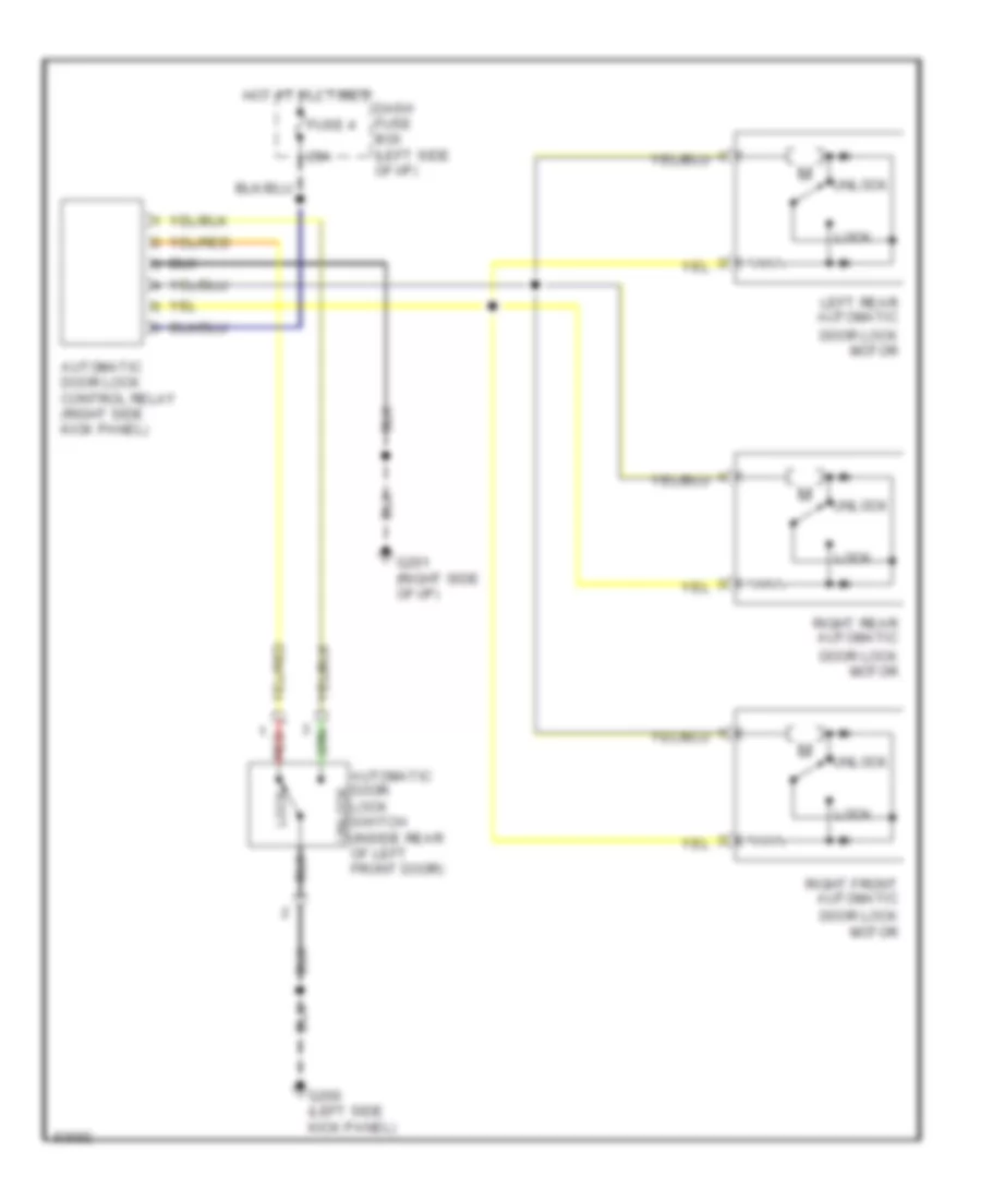
Power Door Lock Wiring Diagram, Early Production for Isuzu Rodeo S 1995
List of elements for Power Door Lock Wiring Diagram, Early Production for Isuzu Rodeo S 1995:
- 25a
- Automatic door lock control relay (right side kick panel)
- Automatic door unlock
- Dash fuse box (left side of i/p)
- Door lock motor
- Fuse 4
- G200 (left side kick panel)
- G201 (right side of i/p)
- Hot at all times
- Left rear automatic
- Lock
- Lock switch (inside rear of left front door)
- Red
- Right front automatic
- Right rear automatic
- Unlock
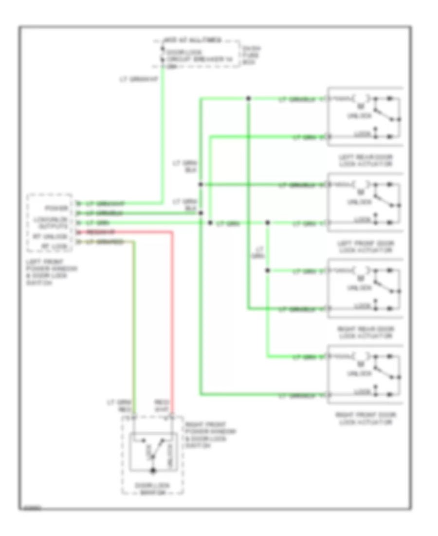
Power Door Lock Wiring Diagram, Late Production for Isuzu Rodeo S 1995
List of elements for Power Door Lock Wiring Diagram, Late Production for Isuzu Rodeo S 1995:
- Dash fuse box
- Door lock circuit breaker 14 20a
- Door lock switch
- Hot at all times
- Lck/unlck outputs
- Left front door lock actuator
- Left front power window & door lock switch
- Left rear door lock actuator
- Lock
- Power
- Right front door lock actuator
- Right front power window & door lock switch
- Right rear door lock actuator
- Rt lock
- Rt unlock
- Unlock
POWER MIRRORS
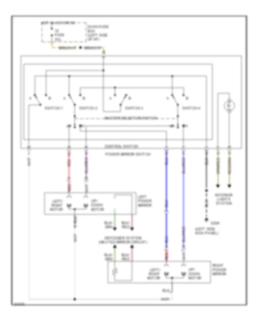
Power Mirror Wiring Diagram, Early Production for Isuzu Rodeo S 1995
List of elements for Power Mirror Wiring Diagram, Early Production for Isuzu Rodeo S 1995:
- (left side kick panel)
- Control switch
- Dash fuse box (left side of i/p)
- Defogger system (heated mirror circuit)
- Fuse 15a
- G200
- Hot in acc or on
- Interior lights system
- Left power mirror
- Left/ right motor
- Master selector switch
- Power mirror switch
- Red
- Right power mirror
- Switch 1
- Switch 2
- Switch 3
- Switch 4
- Up/ down motor
Power Mirror Wiring Diagram, Late Production for Isuzu Rodeo S 1995
List of elements for Power Mirror Wiring Diagram, Late Production for Isuzu Rodeo S 1995:
- Cb-19 audio fuse 15a
- Dash fuse box (left side of i/p)
- G200 (left kick panel)
- Hot in acc or on
- Interior lights
- Left
- Left power mirror
- Left/right
- Mirror selector switch
- Power mirror switch
- Red
- Right
- Right power mirror
- Switch 1
- Switch 2
- Switch 3
- Switch 4
- Up/down
POWER WINDOWS
2.6L
2.6L, Power Window Wiring Diagram, Early Production for Isuzu Rodeo S 1995
List of elements for 2.6L, Power Window Wiring Diagram, Early Production for Isuzu Rodeo S 1995:
- Auto down
- Auto down controller
- C503
- C504
- Circuit breaker 30a
- Dash fuse box (left side of i/p)
- Down
- Fuse 7 10a
- G200 (left side kick panel)
- G201 (right side of i/p)
- Hot at all times
- Hot in on or start
- Left front power window motor
- Left front power window switch
- Left rear power window motor
- Left rear power window switch
- Lock switch
- Off
- Power window relay (right side of i/p, above kick panel)
- Red
- Right front power window motor
- Right front power window switch
- Right rear power window motor
- Right rear power window switch
3.2L
3.2L, Power Window Wiring Diagram, Early Production for Isuzu Rodeo S 1995
List of elements for 3.2L, Power Window Wiring Diagram, Early Production for Isuzu Rodeo S 1995:
- Auto down
- Auto down controller
- C503
- C504
- Circuit breaker 30a
- Dash fuse box (left side of i/p)
- Down
- Fuse 7 10a
- G200 (left side kick panel)
- G201 (right side of i/p)
- Hot at all times
- Hot in on or start
- Left front power window motor
- Left front power window switch
- Left rear power window motor
- Left rear power window switch
- Lock switch
- Off
- Power window relay (right side of i/p, above kick panel)
- Red
- Right front power window motor
- Right front power window switch
- Right rear power window motor
- Right rear power window switch
3.2L, Power Window Wiring Diagram, Late Production for Isuzu Rodeo S 1995
List of elements for 3.2L, Power Window Wiring Diagram, Late Production for Isuzu Rodeo S 1995:
- (not used)
- Back up, turn cb-15 15a
- Dash fuse box
- G200 (above left kick panel)
- G200 (at left kick panel)
- G203 (above right kick panel)
- G203 (at right kick panel)
- Ground
- Hot at all times
- Hot in on or start
- Left front power window & door lock switch
- Left front power window motor
- Left rear power window motor
- Left rear power window switch
- Multiplexed
- Multiplexed win cntl out
- Power
- Power window cb-27 30a
- Power window relay (left kick panel)
- Right front power window & door lock switch
- Right front power window motor
- Right rear power window motor
- Right rear power window switch
- Win cntl in
- Win mtr cntl
RADIO
Radio Wiring Diagrams for Isuzu Rodeo S 1995
List of elements for Radio Wiring Diagrams for Isuzu Rodeo S 1995:
- (-) (-) memory power
- antenna
- power illuminaton (+)
- (+)
- (+) (+)
- (-) (-)
- (cd change bracket)
- (left kick panel) g200
- Antenna
- Audio fuse cb-19 15a
- Cd changer (if equipped)
- Cd player (if equipped)
- Control cable
- Dash fuse box
- Ground
- Hot at all times
- Hot in acc or on
- I-11
- I-41
- Illuminaton
- Interior lights system
- Left front speaker
- Left rear speaker
- Left tweeter
- Nca
- Pnk
- Radio
- Red
- Right front speaker
- Right rear speaker
- Right tweeter
- Room fuse cb-9 10a
SHIFT INTERLOCKS
Shift Interlock Wiring Diagram, Early Production for Isuzu Rodeo S 1995
List of elements for Shift Interlock Wiring Diagram, Early Production for Isuzu Rodeo S 1995:
- (below shift lever cover)
- (not used)
- Battery
- Brake input
- Brake light switch (on brake pedal support)
- C264
- C270
- Charge sig
- Dash fuse box (left side of i/p)
- Fuse 10a
- Fuse/ relay box (right side of engine compartment)
- G200 (left side kick panel)
- Ground
- Hot at all times
- Hot in on or start
- Ignition
- Park input
- Parking switch (below shift lever cover)
- Red
- Ref signal
- Safety lock control unit (below shift lever cover)
- Shift lock solenoid
- Solenoid control
Shift Interlock Wiring Diagram, Late Production for Isuzu Rodeo S 1995
List of elements for Shift Interlock Wiring Diagram, Late Production for Isuzu Rodeo S 1995:
- (1996 m.y.)
- (not used)
- Anti-lock brakes, air conditioning
- Anti-lock brakes, cruise control
- B-32
- Battery
- Brake sw in
- Brake switch (on brake pedal support)
- Cb-13 stop fuse 15a
- Cb-7 meter fuse 15a
- Dash fuse box (left side of i/p)
- G200 (left kick panel)
- Generator (1996 model year only)
- Ground
- Hot at all times
- Hot in on or start
- Ignition
- J-1
- Park input
- Park position switch (below shift lever cover)
- Red
- Ref signal
- Shift lock controller (below shift lever cover)
- Shift lock solenoid (below shift lever cover)
- Sol ctrl
- Starting/ charging
STARTING/CHARGING
2.6L
2.6L, Charging Wiring Diagram, Early Production for Isuzu Rodeo S 1995
List of elements for 2.6L, Charging Wiring Diagram, Early Production for Isuzu Rodeo S 1995:
- Air conditioning system (heater a/c relay)
- Battery
- C200
- C275
- Charge relay
- Charge warning light
- Dash fuse box
- Engine controls system
- Fuse 10a
- Fuse/ relay box
- Fuse/relay box
- G101 (right side of engine compartment, behind battery)
- G101 (right side of engine compartment, on inner fender panel)
- G119 (right front of engine, below intake manifold)
- G120 (lower right side of engine compartment, on frame)
- Generator
- Hot in on or start
- Instrument cluster
- Main fuse 1 60a
- Power distribution system
- Starting system (starter solenoid)
2.6L, Charging Wiring Diagram, Late Production for Isuzu Rodeo S 1995
List of elements for 2.6L, Charging Wiring Diagram, Late Production for Isuzu Rodeo S 1995:
- Battery
- Charge fuse 6 10a
- Charge relay
- Charge warning light
- Dash fuse box
- Engine controls system
- Engine device fuse 3 15a
- Fuse/ relay box
- G101 (right side of engine compartment, behind battery)
- G101 (right side of engine compartment, on inner fender panel)
- G119 (right front of engine, below intake manifold)
- G120 (lower right side of engine compartment, on frame)
- Generator
- Hot in on or start
- I-15
- I-16
- Instrument cluster
- Main fuse 16 100a
- Meter fuse 15a
- Power distribution system
- Starting system (starter solenoid)
2.6L, Starting Wiring Diagram, Early Production for Isuzu Rodeo S 1995
List of elements for 2.6L, Starting Wiring Diagram, Early Production for Isuzu Rodeo S 1995:
- Acc
- Battery
- C211
- Clutch start switch (behind left side of i/p, on clutch pedal support)
- Dash fuse box
- Engine control module (ecm) (below left side of i/p, at kick panel)
- Fuse 11 10a
- Fuse/ relay box
- G101 (right side of engine compartment, below battery)
- G119 (right front of engine, below intake manifold)
- G120 (lower right side of engine compartment, on frame)
- Hold-in coil
- Ignition switch
- Ignition switch input
- Lock
- Main fuse 1 60a
- Pull-in coil
- Start
- Starter
- Starter motor
- Starter solenoid
2.6L, Starting Wiring Diagram, Late Production for Isuzu Rodeo S 1995
List of elements for 2.6L, Starting Wiring Diagram, Late Production for Isuzu Rodeo S 1995:
- Acc
- Battery
- Clutch start switch (behind left side of i/p, on clutch pedal support)
- Dash fuse box
- Engine controls system
- Fuse/ relay box
- Fuse/relay box
- G101 (right side of engine compartment, below battery)
- G101 (right side of engine compartment, on inner fender panel)
- G119 (right front of engine, below intake manifold)
- G120 (lower right side of engine compartment, on frame)
- Hold-in coil
- Ignition switch
- Lock
- Main fuse 16 100a
- Pull-in coil
- Start
- Starter
- Starter fuse 1 10a
- Starter motor
- Starter relay
- Starter solenoid
3.2L
3.2L, Charging Wiring Diagram, Early Production for Isuzu Rodeo S 1995
List of elements for 3.2L, Charging Wiring Diagram, Early Production for Isuzu Rodeo S 1995:
- Air conditioning system (heater a/c relay)
- Battery
- C200
- C274
- C275
- Charge relay
- Charge warning light
- Dash fuse box
- Fuse 10a
- Fuse/ relay box
- Fuse/relay box
- G101 (right side of engine compartment, behind battery)
- G101 (right side of engine compartment, on inner fender panel)
- G119 (right front corner of engine, above generator)
- G120 (lower right side of engine compartment, on frame)
- Generator
- Hot in on or start
- Instrument cluster
- Main fuse 1 60a
- Power distribution system
- Starting system (starter solenoid)
3.2L, Charging Wiring Diagram, Late Production for Isuzu Rodeo S 1995
List of elements for 3.2L, Charging Wiring Diagram, Late Production for Isuzu Rodeo S 1995:
- (not used)
- Air conditioning system
- Battery
- Charge fuse 6 10a
- Charge relay
- Charge warning light
- Dash fuse box
- Engine device fuse 3 15a
- Fuse/ relay box
- G101 (right side of engine compartment, on inner fender panel)
- G119 (right front corner of engine, above generator)
- G120 (lower right side of engine compartment, on frame)
- Generator
- Hot in on or start
- I-15
- I-16
- I-26
- Instrument cluster
- Main fuse 16 100a
- Meter fuse 7 15a
- Starting system (starter solenoid)
3.2L, Starting Wiring Diagram, A/T Early Production for Isuzu Rodeo S 1995
List of elements for 3.2L, Starting Wiring Diagram, A/T Early Production for Isuzu Rodeo S 1995:
- (left rear corner of engine compartment, on inner fender panel)
- Acc
- Automatic transmission mode switch (on left side of transmission)
- Battery
- C219
- Dash fuse box
- Diode box a
- Diode box b
- Engine control module (ecm) (left kick panel) input
- Fuse 10a
- Fuse/relay box
- G101 (right side of engine compartment, behind battery)
- G104
- G119 (right front corner of engine, above generator)
- G120 (lower right side of engine, compartment, on frame)
- Ignition switch
- Lock
- Main fuse 1 60a
- Neutral park/
- Off
- Start
- Starter
- Starter motor
- Starter relay
- Starter solenoid
- Tailgate release system
3.2L, Starting Wiring Diagram, A/T Late Production for Isuzu Rodeo S 1995
List of elements for 3.2L, Starting Wiring Diagram, A/T Late Production for Isuzu Rodeo S 1995:
- (left rear corner of engine compartment, on inner fender panel)
- Acc
- Automatic transmission mode switch (on left side of transmission)
- Battery
- Dash fuse box
- Diode box a
- Engine controls system
- Fuse/ relay box
- G101 (right side of engine compartment, behind battery)
- G104
- G119 (right front corner of engine, above generator)
- G120 (lower right side of engine, compartment, on frame)
- Hatch glass release system
- Ignition switch
- Lock
- Main fuse 16 100a
- Off
- Start
- Starter
- Starter fuse 1 10a
- Starter motor
- Starter relay
- Starter solenoid
3.2L, Starting Wiring Diagram, M/T Early Production for Isuzu Rodeo S 1995
List of elements for 3.2L, Starting Wiring Diagram, M/T Early Production for Isuzu Rodeo S 1995:
- Acc
- Battery
- Clutch start switch (behind left side of i/p, on clutch pedal support)
- Dash fuse box
- Fuse 11 10a
- Fuse/ relay box
- Fuse/relay box
- G101 (right side of engine compartment, behind battery)
- G101 (right side of engine compartment, on inner fender panel)
- G119 (right front corner of engine, above generator)
- G120 (lower right side of engine compartment compartment, on frame)
- Hold-in coil
- Ignition switch
- Lock
- Main fuse 1 60a
- Pull-in coil
- Start
- Starter
- Starter motor
- Starter relay
- Starter solenoid
3.2L, Starting Wiring Diagram, M/T Late Production for Isuzu Rodeo S 1995
List of elements for 3.2L, Starting Wiring Diagram, M/T Late Production for Isuzu Rodeo S 1995:
- Acc
- Battery
- Clutch start switch (behind left side of i/p, on clutch pedal support)
- Dash fuse box
- Fuse/ relay box
- Fuse/relay box
- G101 (right side of engine compartment, behind battery)
- G101 (right side of engine compartment, on inner fender panel)
- G119 (right front corner of engine, above generator)
- G120 (lower right side of engine compartment compartment, on frame)
- Hold-in coil
- Ignition switch
- Lock
- Main fuse 16 100a
- Pull-in coil
- Start
- Starter
- Starter fuse 1 10a
- Starter motor
- Starter relay
- Starter solenoid
SUPPLEMENTAL RESTRAINTS
Supplemental Restraint Wiring Diagram for Isuzu Rodeo S 1995
List of elements for Supplemental Restraint Wiring Diagram for Isuzu Rodeo S 1995:
- (1995)
- (1996-97)
- (left kick panel)
- (left rear of engine compt)
- -97
- 1996-97
- Air bag warning indicator
- Cable reel (top of steering column)
- Dash fuse box (left side of dash)
- Driver's inflator module
- Driver's seat belt switch (in belt buckle)
- Fuse cb-21 10a
- Fuse cb-22 10a
- G104
- G200
- G206 (center of dash)
- G302 (below center console)
- Gauge assembly
- Hot in on or start
- I-28
- Of dash)
- Passenger's inflator module
- Red
- Srs data link connector (1995) data link connector (1996-97) (left side
- Srs unit (behind front console)
- Steering wheel
TRANSMISSION
3.2L
3.2L, Transmission Wiring Diagram, Early Production for Isuzu Rodeo S 1995
List of elements for 3.2L, Transmission Wiring Diagram, Early Production for Isuzu Rodeo S 1995:
- (brake pedal bracket)
- 1-2/3-4 shift solenoid
- 1-2/3-4 sol
- 1995 vftc c
- 2-3 shift solenoid
- 2-3 sol
- 5v ref
- A/c comp rly
- A/c request
- A/t oil temp indic
- A10
- A11
- A12
- Air conditioning system
- Automatic transmission mode switch (left side of transmission)
- Automatic transmission warning/indicator assembly
- B10
- B11
- B12
- Baro sens
- Barometric pressure sensor (high altitude vehicles only) (left side of engine compartment)
- Battery input
- Brake light switch
- Brake sw input
- C10
- C11
- C12
- C13
- C14
- C15
- C16
- C234
- C236
- C326
- C327
- Check trans indic
- Chk trans ind
- Coolant temp
- Cruise control system
- D10
- D11
- D12
- D13
- D14
- D15
- D16
- Dash fuse box (left i/p)
- Data link connector (left kick panel)
- Diag input
- Diagnostic connector (left kick panel)
- Ecm fuse 30a
- Ect sens
- Electronic ignition system
- Eng rpm input
- Eng rpm out
- Engine control module (left kick panel)
- Engine control module relay
- Exterior lights system
- Force motor (pressure regulator solenoid)
- Force mtr ctrl
- Fuse 2 10a
- Fuse 5 10a
- Fuse 7 10a
- Fuse 8 10a
- Fuse/relay box (right engine compartment)
- G104 (rear of left front fender)
- G112 (ahead of starter)
- G125 (intake manifold)
- Ground
- Hot at all times
- Hot in on or start
- Ign input
- Ignition control module
- Illum.
- Interior lights system
- Kick down switch (behind left i/p)
- Kickdn sw
- O/d off input
- Oil temp ind
- Pnk
- Power
- Power drive indic
- Power/winter switch
- Pwr drive ind
- Pwr mode enab
- Red
- Reference
- Serial data
- Starting/ charging system
- Tccs ctrl
- Throt pos sens
- Throttle position sensor (top left side of engine)
- Torque convertor clutch solenoid
- Tps input
- Trans oil temp
- Transmission
- Transmission control module
- Transmission control module (above left kick panel)
- Transmission oil temperature sensor
- Transmission position inputs
- Transmission speed sensor (left rear of transmission)
- Vss input
- Wint drive ind
- Wint mode enab
- Winter
- Winter drive indic
3.2L, Transmission Wiring Diagram, Late Production for Isuzu Rodeo S 1995
List of elements for 3.2L, Transmission Wiring Diagram, Late Production for Isuzu Rodeo S 1995:
- (brake pedal bracket)
- 1-2/3-4 shift solenoid
- 1-2/3-4 sol
- 1995 vftc c
- 2-3 shift solenoid
- 2-3 sol
- 5v ref
- A/c comp rly
- A/t oil temp indic
- A10
- A11
- A12
- Air conditioning system
- Automatic transmission mode switch (left side of transmission)
- Automatic transmission warning/indicator assembly
- B10
- B11
- B12
- Baro sens
- Battery input
- Brake light switch
- Brake sw input
- C10
- C11
- C12
- C13
- C14
- C15
- C16
- Cb-13 fuse 10a
- Cb-15 fuse 15a
- Cb-3 fuse 10a
- Cb-7 fuse 10a
- Check trans indic
- Chk trans ind
- Coolant temp
- Cruise control system
- D10
- D11
- D12
- D13
- D14
- D15
- D16
- Dash fuse box (left i/p)
- Data link connector (left kick panel)
- Diag input
- Diagnostic connector (left kick panel)
- Eb-12 fuse 15a
- Ecm main relay
- Ect sens
- Electronic ignition system
- Eng rpm input
- Eng rpm out
- Engine control module (left kick panel)
- Exterior lights system
- Force motor (pressure regulator solenoid)
- Force mtr ctrl
- Fuse/relay box (right engine compartment)
- G104 (rear of left front fender)
- G112 (ahead of starter)
- G125 (intake manifold)
- Ground
- Hot at all times
- Hot in on or start
- Ign input
- Ignition control module
- Illum.
- Interior lights system
- Kick down switch (behind left i/p)
- Kickdn sw
- O/d off input
- Oil temp ind
- Pnk
- Power
- Power drive indic
- Power/winter switch
- Pwr drive ind
- Pwr mode enab
- Red
- Serial data
- Starting/ charging system
- Tccs ctrl
- Throt pos sens
- Throttle position sensor (top left side of engine)
- Torque convertor clutch solenoid
- Tps input
- Trans oil temp
- Transmission
- Transmission control module
- Transmission control module (above left kick panel)
- Transmission oil temperature sensor
- Transmission position inputs
- Transmission speed sensor (left rear of transmission)
- Vss input
- Wint drive ind
- Wint mode enab
- Winter
- Winter drive indic
TRUNK, TAILGATE, FUEL DOOR
Rear Glass Release Wiring Diagram, Early Production for Isuzu Rodeo S 1995
List of elements for Rear Glass Release Wiring Diagram, Early Production for Isuzu Rodeo S 1995:
- (a/t)
- (m/t)
- Automatic transmission mode switch (beneath center of vehicle, on left side of transmission)
- Dash fuse box (left side of i/p)
- Diode box a
- Diode box c (behind left side of i/p)
- Fuse 25a
- Fuse/ relay box (right side of engine compt)
- G104 (rear of left front fender)
- Hot at all times
- Int
- Interior lights system
- Nca
- Off
- Park
- Parking brake switch (under center console, on parking brake lever)
- Rear wiper motor on switch (inside right side of tailgate on wiper motor linkage)
- Rear wiper/ washer switch
- Run
- Tailgate glass opener actuator (inside center of tailgate)
- Tailgate opener switch
- Wipe
Rear Glass Release Wiring Diagram, Late Production for Isuzu Rodeo S 1995
List of elements for Rear Glass Release Wiring Diagram, Late Production for Isuzu Rodeo S 1995:
- (1995 m.y.)
- (1996 m.y.)
- 1995 only
- A/t
- Automatic transmission mode switch (left side of transmission)
- Cb-17 rr def 1 fuse 15a
- Cb-18 rr def 2 fuse 15a
- Dash fuse box (left side of i/p)
- Diode box a
- Fuse/ relay box
- G104 (left rear of engine compt)
- H-1
- H-23
- H-37
- Hatch gate glass opener actuator (center of tailgate)
- Hatch gate glass opener switch
- Hatch gate open switch (center of tailgate)
- Hatch open ind
- Hot at all times
- Instrument cluster
- Interior lights
- M/t
- Off
- Park
- Parking brake switch (under center console)
- Rear washer switch
- Rear wiper motor on switch (right side of tailgate)
- Rear wiper switch
- Run
- Starter relay
- Starting/ charging
- Wash
- Wipe
WARNING SYSTEMS
Warning System Wiring Diagrams, Early Production for Isuzu Rodeo S 1995
List of elements for Warning System Wiring Diagrams, Early Production for Isuzu Rodeo S 1995:
- (2.6l) (3.2l)
- Control
- Dash fuse box (left side of i/p)
- Door open
- Driver's seat belt switch (in left front seat belt buckle)
- Fuse 10a
- G200 (left side kick panel)
- G201 (right side of i/p)
- Ground
- Head
- Hot at all times
- Hot in on or start
- Ignition
- Input
- Instrument cluster
- Key in ignition input
- Key remind switch (on ignition switch)
- Left front door switch (rear of left front door area)
- Light switch
- Lights on input
- Off
- Park
- Red
- Seat belt unbuckle input
- Seat belt warning light
- Warning buzzer control unit (right side kick panel)
- Warning light
Warning System Wiring Diagrams, Late Production for Isuzu Rodeo S 1995
List of elements for Warning System Wiring Diagrams, Late Production for Isuzu Rodeo S 1995:
- (2.6l) (3.2l)
- Anti-theft connector (1996 model year only)
- Belt unbuckled
- Cb-5 tail-illum fuse 15a
- Cb-7 meter fuse 10a
- Cb-9 room fuse 10a
- Dash fuse box (left side of i/p)
- Door open
- G200 (left kick panel)
- G203 (right kick panel)
- Ground
- Head
- Hot at all times
- Hot in on or start
- Ignition
- Ignition switch
- Input
- Interior lights
- Key in ignition input
- Key reminder switch
- Left front door switch (at door striker)
- Left front seat belt switch (in seat belt buckle)
- Lighting switch
- Lights on input
- Meter assembly
- Off
- Park
- Red
- Seat belt warning light
- Seat belt, key and light reminder buzzer (below right side of i/p near kick panel)
- Tail light relay (behind left kick panel)
WIPER/WASHER
2-Speed Wiper/Washer Wiring Diagram, Early Production for Isuzu Rodeo S 1995
List of elements for 2-Speed Wiper/Washer Wiring Diagram, Early Production for Isuzu Rodeo S 1995:
-
- (not used)
- (right rear corner of eng compt, on bulkhead)
- 15a
- Fuse 6
- G101 (right front fender)
- G104 (rear of left fender)
- Hot in on or start
- Interior lights system
- Mist
- Off
- Park
- Run
- Wash
- Washer button illumi- nation
- Wind- shield wiper/ washer switch
- Windshield washer motor (in washer fluid reservoir)
- Windshield wiper motor
- Windshield wiper relay connector plug (fuse/relay box)
- Wiper switch illumi- nation
2-Speed Wiper/Washer Wiring Diagram, Late Production for Isuzu Rodeo S 1995
List of elements for 2-Speed Wiper/Washer Wiring Diagram, Late Production for Isuzu Rodeo S 1995:
- (not used)
- Combination switch
- Dash fuse box
- Front wiper fuse cb-11 2oa
- G104 (rear of left front fender)
- G105 (rear of right front fender)
- Hot in on or start
- Intermittent windshield wiper relay connector plug (right rear corner of engine compartment)
- Mist
- Off
- Park
- Run
- Wash
- Wind- shield washer motor (in washer fluid reservoir)
- Windshield wiper motor (right rear corner of engine compartment)
- Windshield wiper/washer switch
Interval Wiper/Washer Wiring Diagram, Early Production for Isuzu Rodeo S 1995
List of elements for Interval Wiper/Washer Wiring Diagram, Early Production for Isuzu Rodeo S 1995:
-
- (middle of right front fender)
- (rear of left front fender)
- (right rear corner of eng compt, on bulkhead)
- 15a
- Coil control
- Fuse 6
- G101
- G104
- Gnd
- Hot in on or start
- Int
- Interior lights system
- Intermittent input
- Off
- Park
- Power input
- Run
- Timer
- Wash
- Washer button illumi- nation
- Washer input
- Wind- shield wiper/ washer switch
- Windshield washer motor (in washer fluid reservoir)
- Windshield wiper motor
- Windshield wiper relay (fuse/relay box)
- Wiper switch illumi- nation
Interval Wiper/Washer Wiring Diagram, Late Production for Isuzu Rodeo S 1995
List of elements for Interval Wiper/Washer Wiring Diagram, Late Production for Isuzu Rodeo S 1995:
- Combination switch
- Dash fuse box
- Front wiper fuse cb-11 2oa
- G104 (rear of left front fender)
- G105 (rear of right front fender)
- Hot in on or start
- Int
- Intermittent windshield wiper relay (right rear corner of engine compartment)
- Mist
- Off
- Park
- Run
- Timer
- Wash
- Wind- shield washer motor (in washer fluid reservoir)
- Windshield wiper motor (right rear corner of engine compartment)
- Windshield wiper/washer switch
Rear Wiper/Washer Wiring Diagram, Early Production for Isuzu Rodeo S 1995
List of elements for Rear Wiper/Washer Wiring Diagram, Early Production for Isuzu Rodeo S 1995:
- Dash fuse box (left side of i/p)
- Diode box e (left side of trunk)
- Fuse 10a
- G200 (left side kick panel)
- Hatch gate open switch (inside top center of tailgate)
- Hatch release system
- Hot in on or start
- Int
- Off
- Park
- Rear washer motor (in washer fluid reservoir)
- Rear wiper controller (left side of truck)
- Rear wiper motor (inside right side of tailgate)
- Rear wiper relay (left side of trunk)
- Rear wiper/ washer switch
- Red
- Run
- Wash
- Wipe
Rear Wiper/Washer Wiring Diagram, Late Production for Isuzu Rodeo S 1995
List of elements for Rear Wiper/Washer Wiring Diagram, Late Production for Isuzu Rodeo S 1995:
- (left side of luggage room)
- (top center of tailgate)
- Dash fuse box
- Diode box e
- G200 (left kick panel)
- Hatch open switch
- Hot in on or start
- Interior lights system
- Off
- Park
- Rear washer motor (left side of luggage room, in washer fluid reservoir)
- Rear washer switch
- Rear wiper controller (left side of luggage room, behind lower trim cover)
- Rear wiper fuse cb-16 10a
- Rear wiper motor (inside right side of tailgate)
- Rear wiper relay (left side of luggage room)
- Rear wiper switch
- Red
- Run
- Trunk, tailgate, fuel door system
- Wash
- Wipe

 Čeština
 Dansk
Dansk Deutsch
 Ελληνικά
 English
 English
 Español
 Suomi
Suomi Français
 Français
 עברית
עברית Hrvatski
 Magyar
 Italiano
 日本語
日本語 한국어
한국어 Nederlands
 Polski
 Português
 Português
 Română
 Русский
 Slovenčina
 Slovenščina
 Türkçe
 中文 (中国)