AIR CONDITIONING
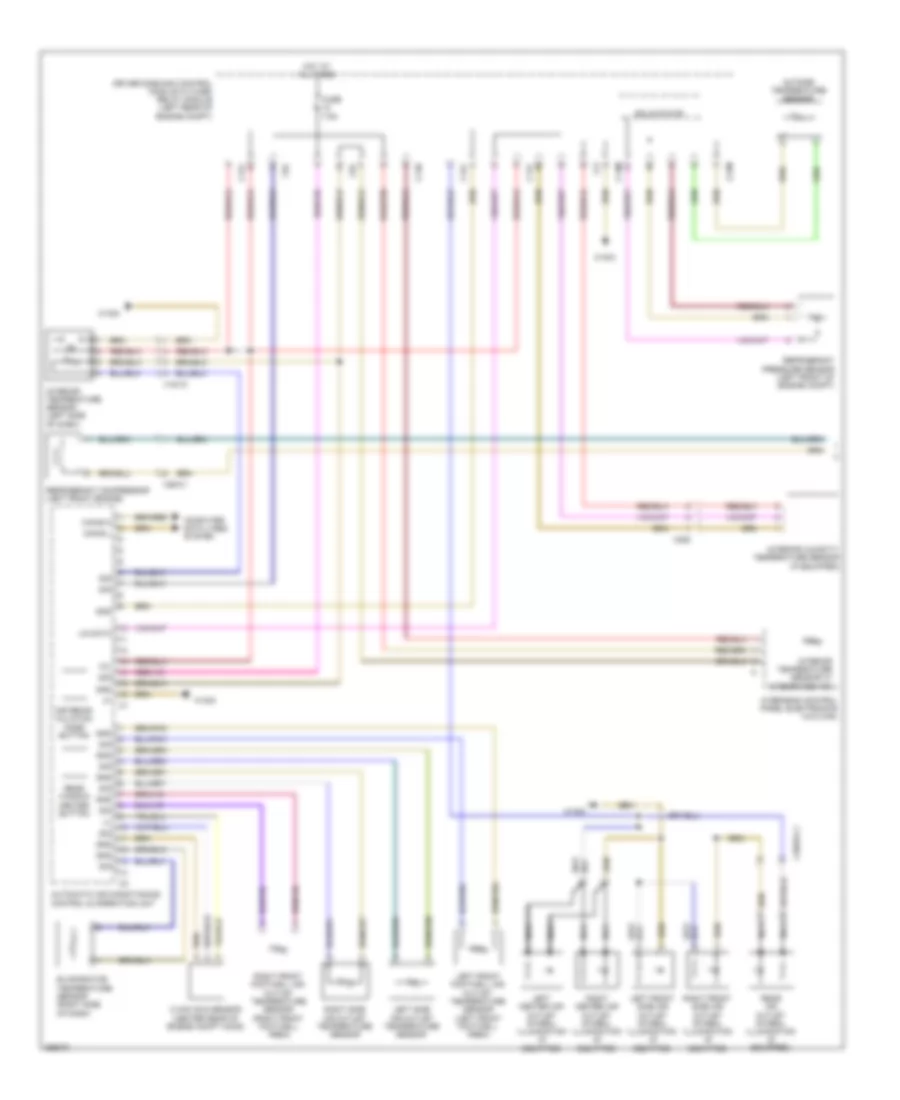
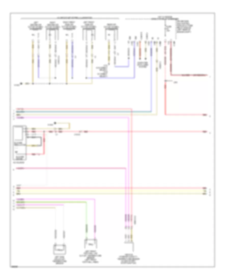
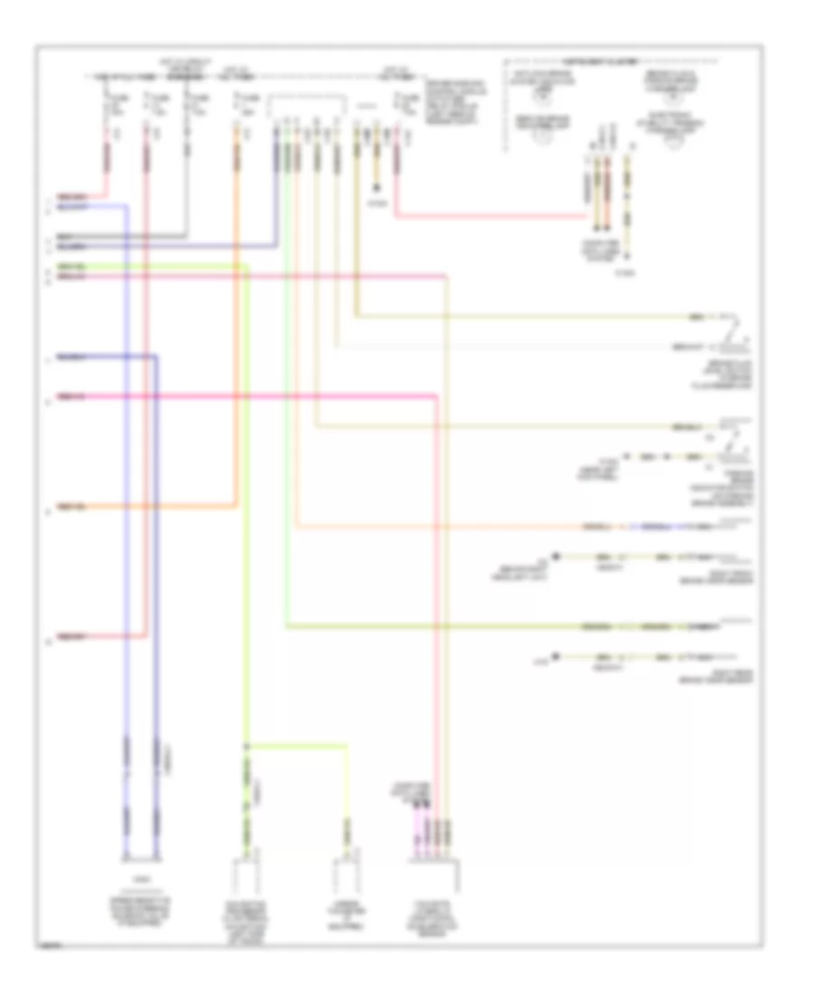
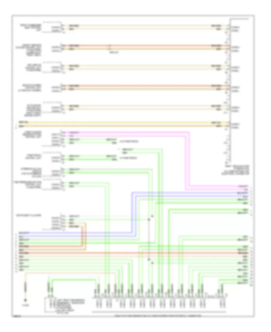
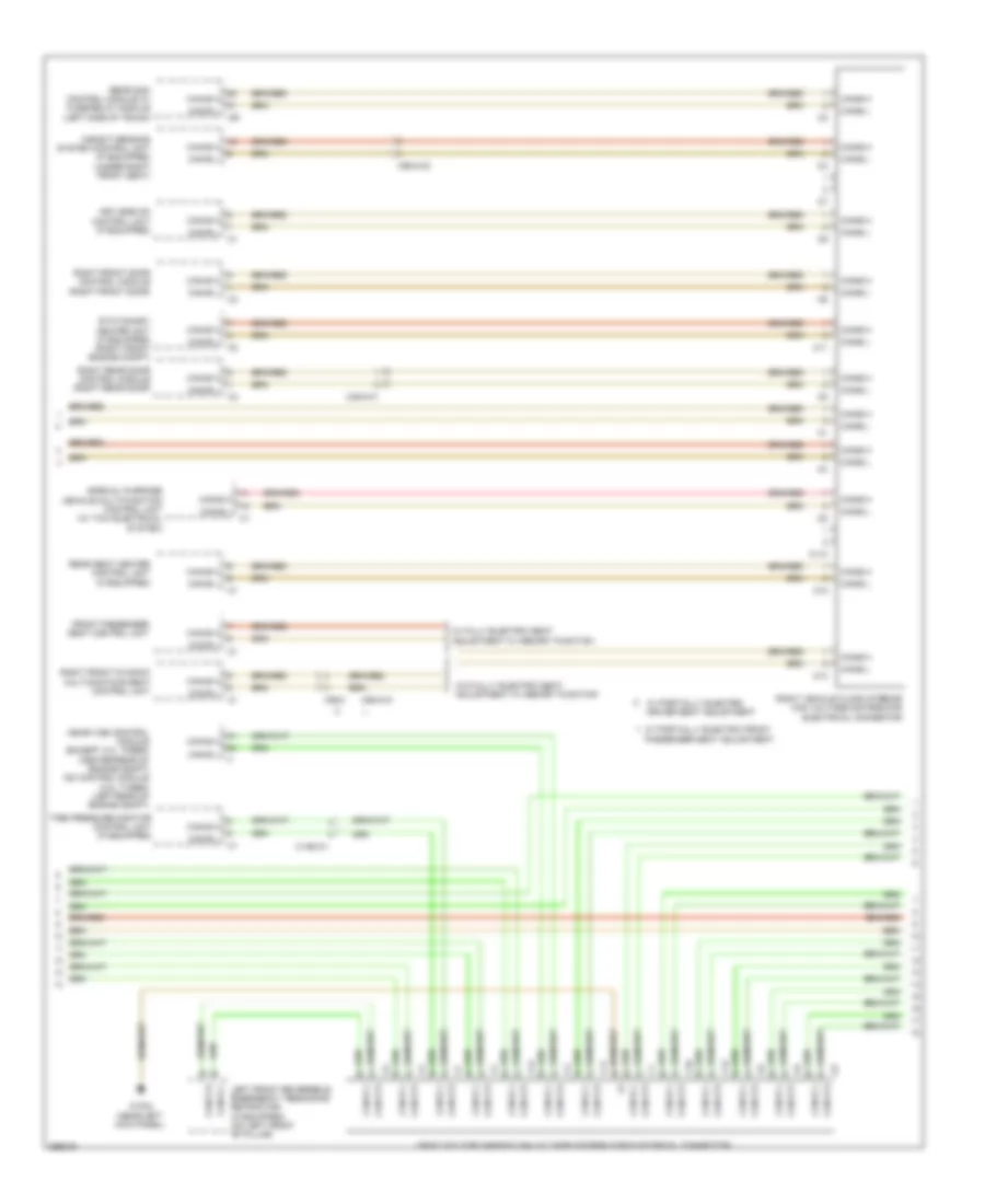
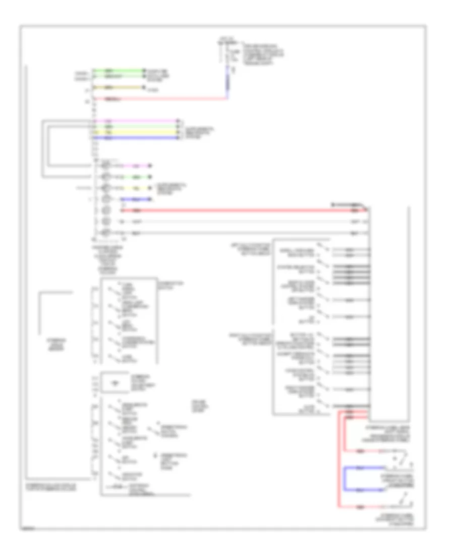
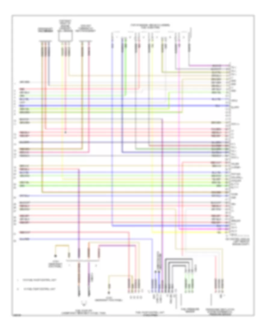
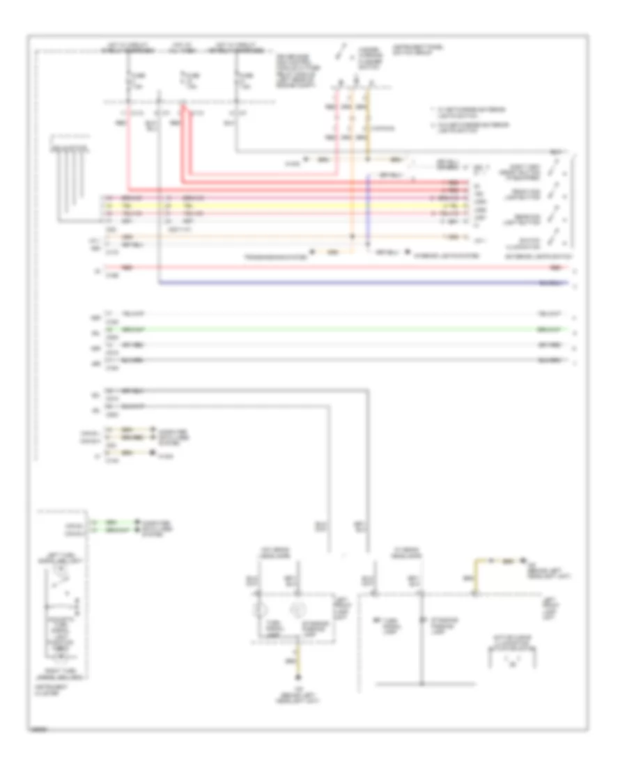
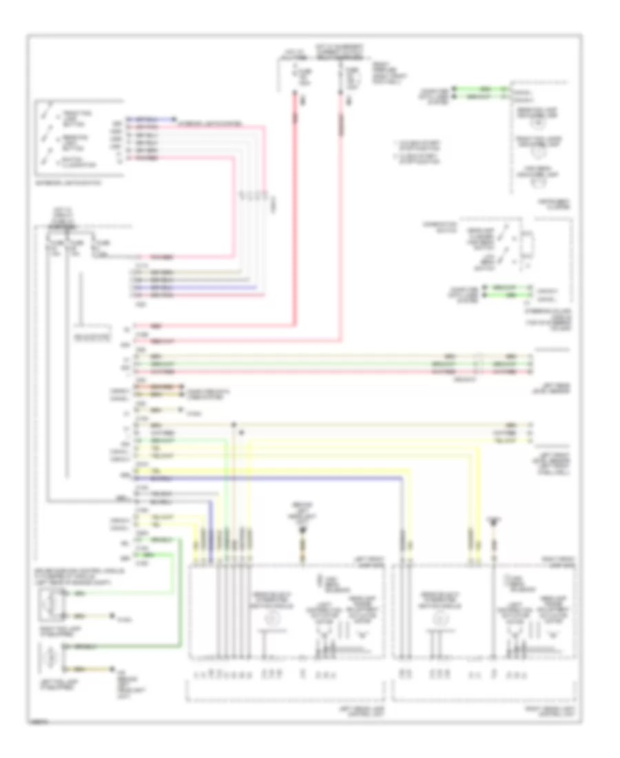
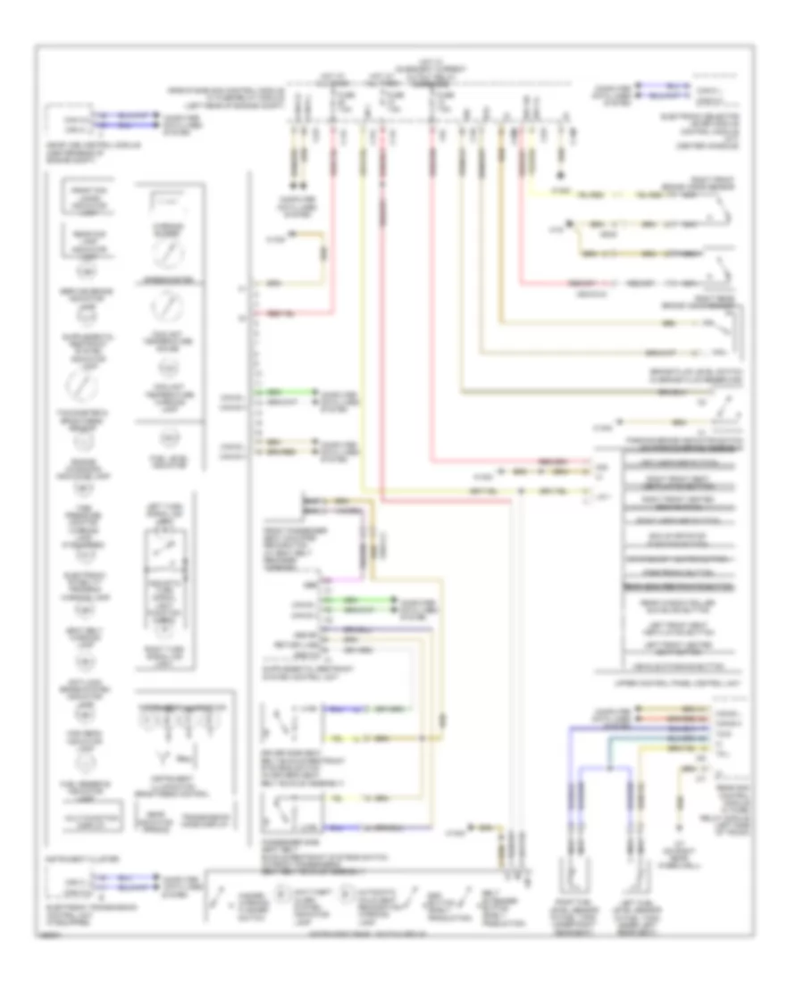
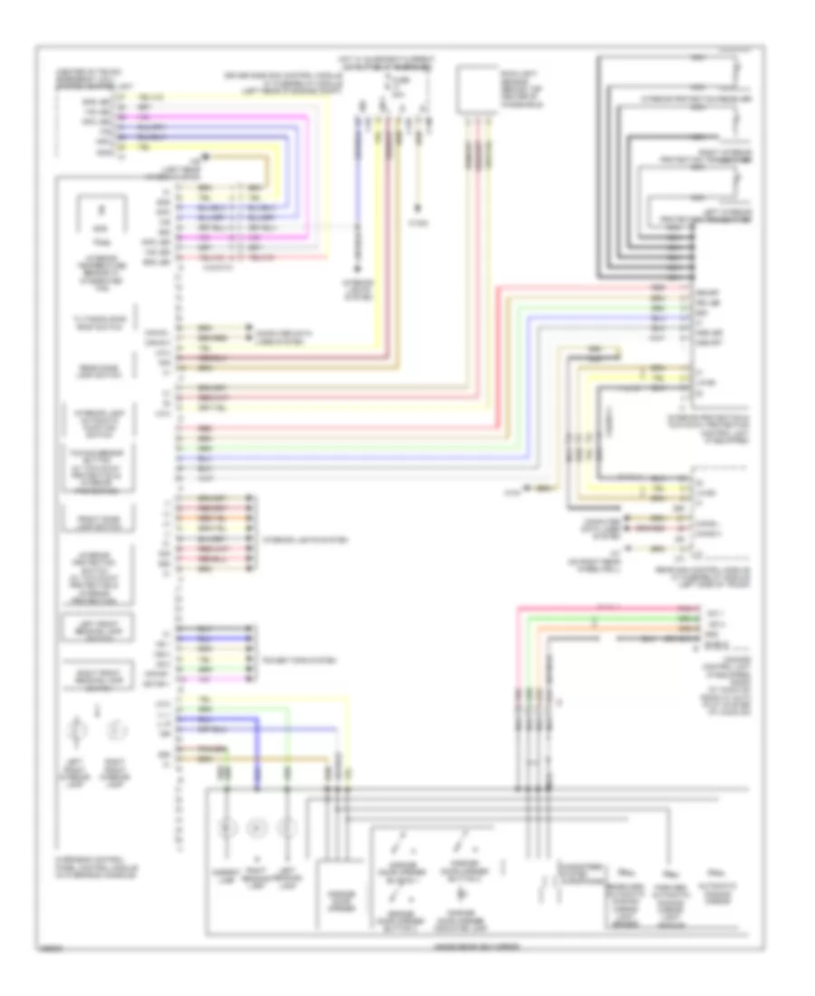
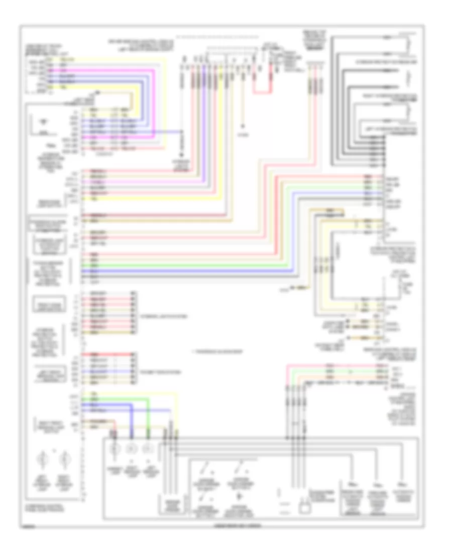
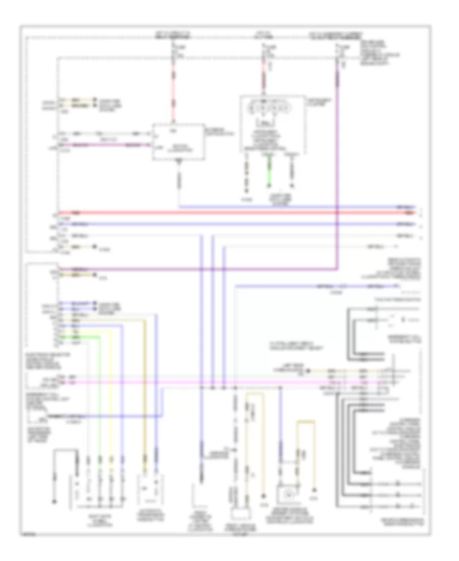
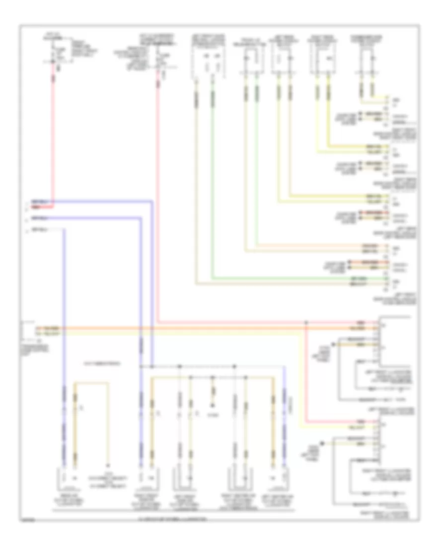
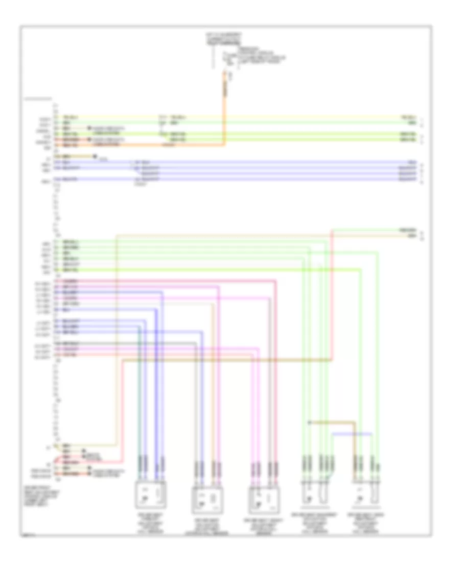
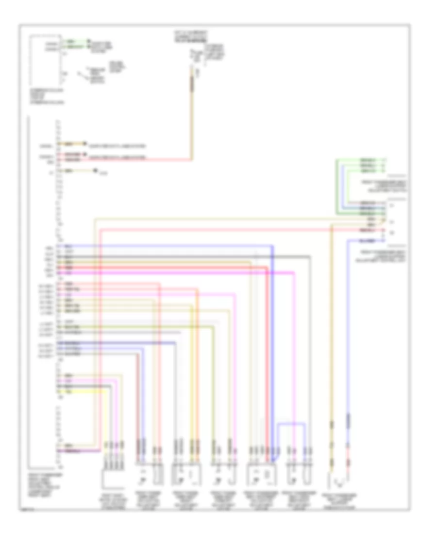
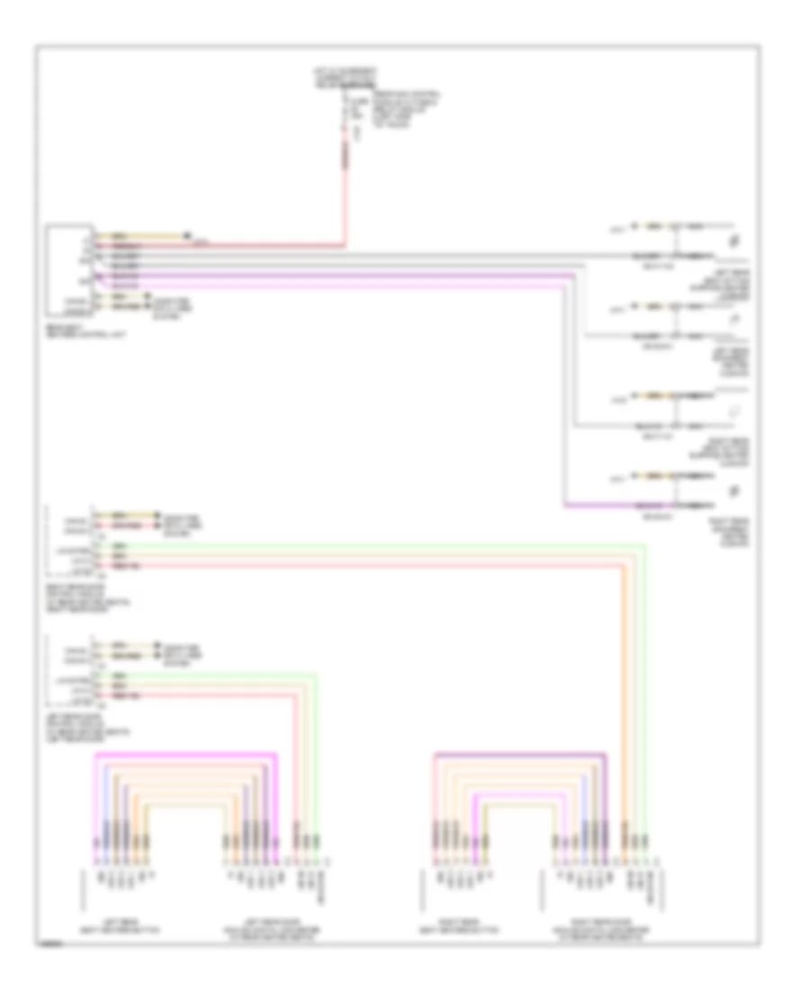
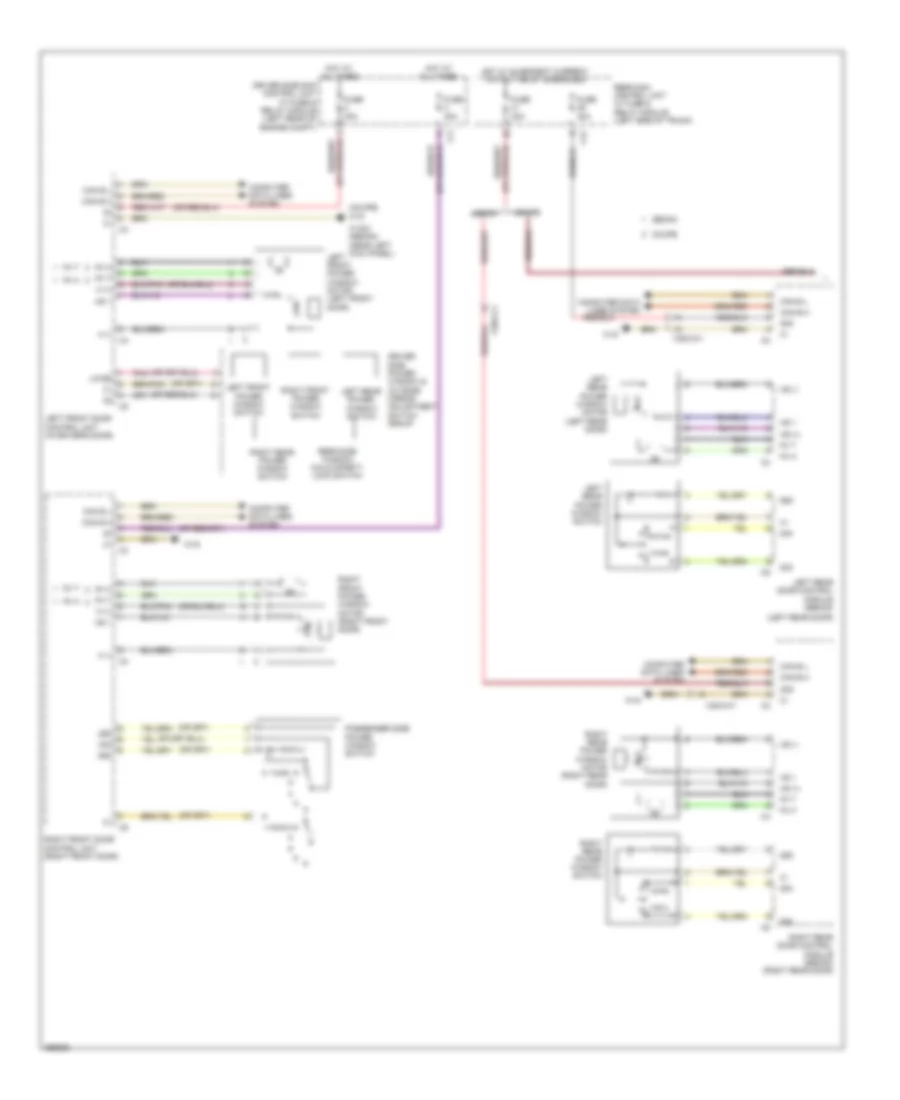
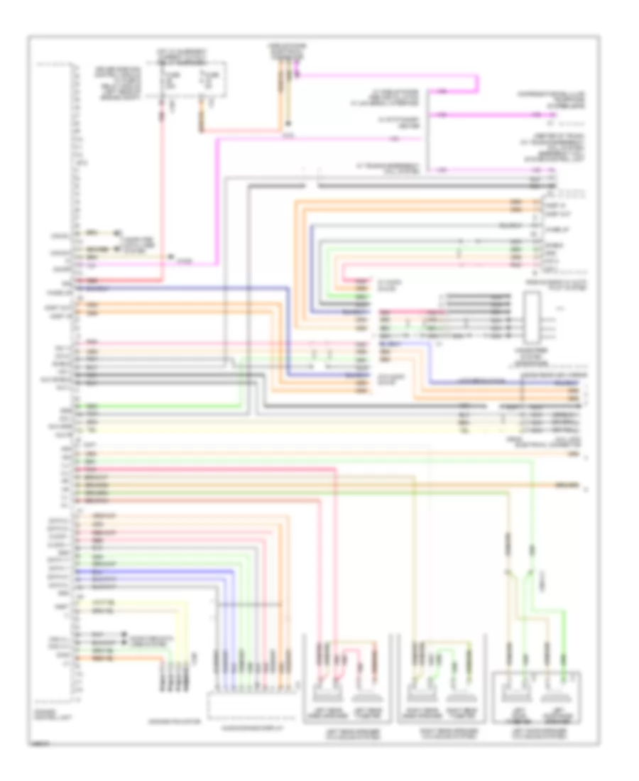
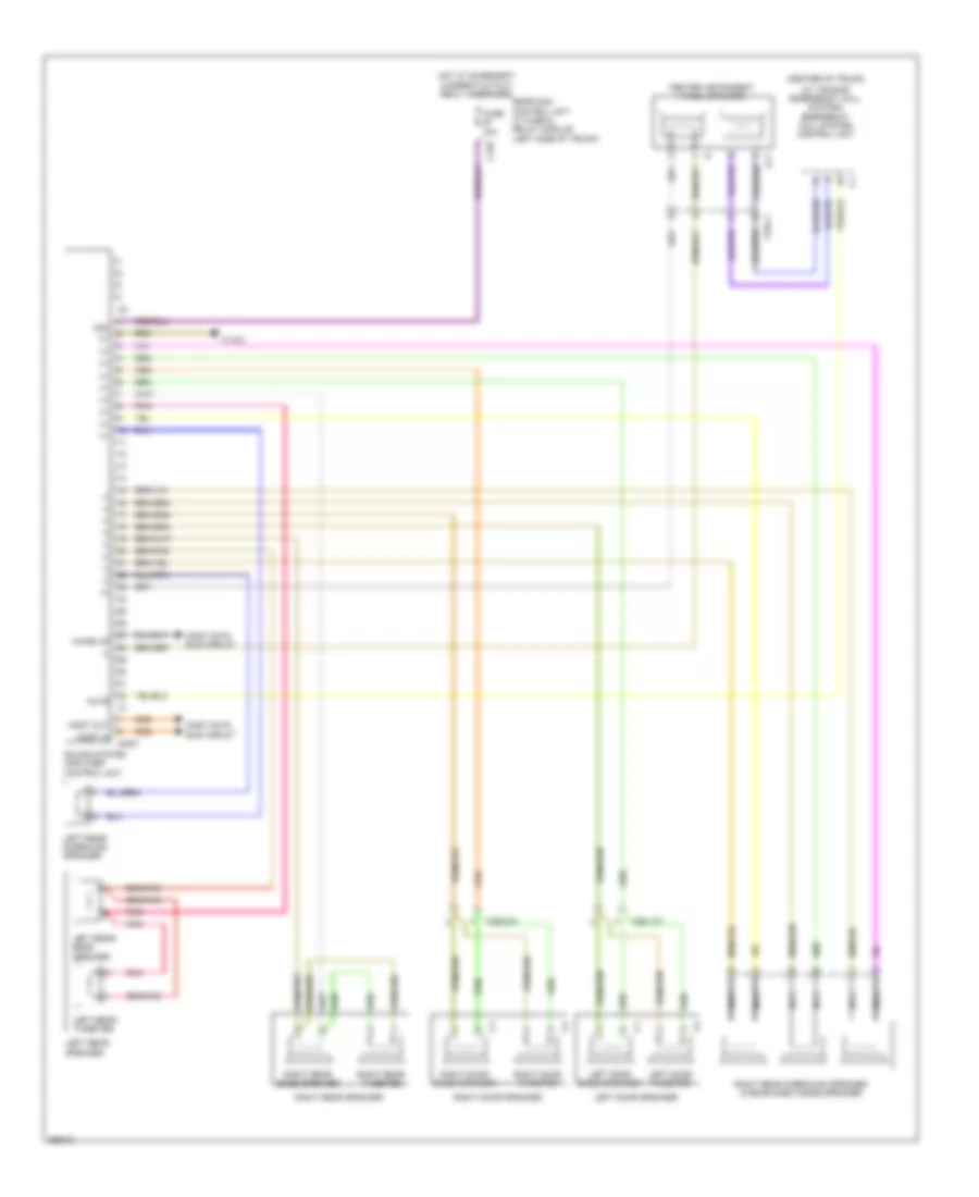
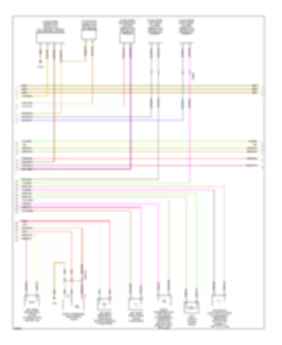
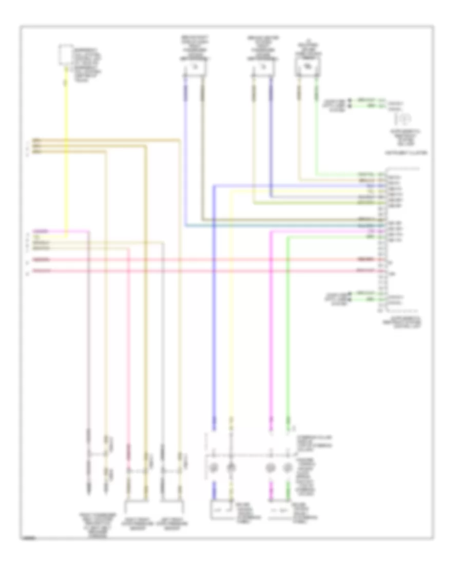
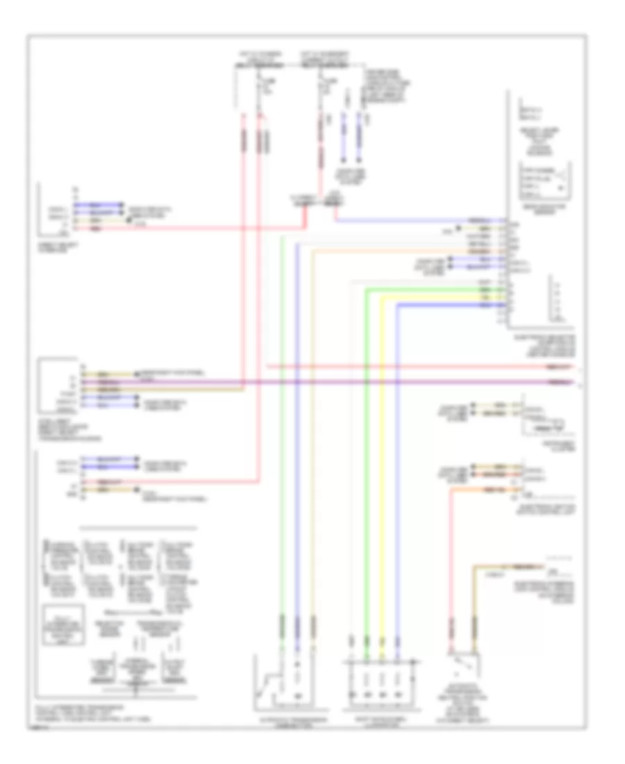
Automatic A/C Wiring Diagram, Coupe with Thermotronic (1 of 2) for Mercedes-Benz E350 2011
 https://portal-diagnostov.com/license.html
Automotive Electricians Portal FZCO
Automotive Electricians Portal FZCO
https://portal-diagnostov.com/license.html
https://portal-diagnostov.com/license.html
Automotive Electricians Portal FZCO
Automotive Electricians Portal FZCO
List of elements for Automatic A/C Wiring Diagram, Coupe with Thermotronic (1 of 2) for Mercedes-Benz E350 2011:
- (+)
- (center rear of engine compt hood)
- 12v
- 58d
- Air recir- culation mode button
- Automatic air conditioning control & operating unit
- C-aac sun sensor
- C11c
- C13d
- C14m
- C17c
- C18m
- C21m
- C5c
- C7i
- Can-b h
- Can-b l
- Computer data lines system
- Data
- Data fond
- Driver side sam control module w/ fuse/ relay module (left rear of engine compt)
- Emission sensor
- Evaporator temperature sensor (right side of dash)
- Fuse 7.5a
- Gnd
- Hot at all times
- Interior humidity/ temperature sensor (if equipped)
- Interior temperature sensor (left side of dash)
- Interior temperature sensor w/ integrated fan
- Left center air outlet symbol illumination (if equipped)
- Left front footwell air outlet temperature sensor (left front footwell area)
- Left front side air outlet symbol illumination (if equipped)
- Left side air outlet temperature sensor
- Lin data
- Nca
- Outside temperature sensor
- Overhead control panel electronics (w/o can)
- Rear air outlet symbol illumination (if equipped)
- Rear automatic air conditioning operating unit
- Rear footwell air outlet temperature sensor
- Rear window heater button
- Refrigerant compressor (left front engine)
- Refrigerant pressure sensor (left front of engine compt)
- Right center air outlet symbol illumination (if equipped)
- Right front footwell air outlet temperature sensor (right front footwell area)
- Right front side air outlet symbol illumination (if equipped)
- Right side air outlet temperature sensor
- Sig
- Solid state
- W/ air outlet symbol illumination
- W15/5
- W16/3
- X15/12
- X18/35-c1
- X226
- X26-c1
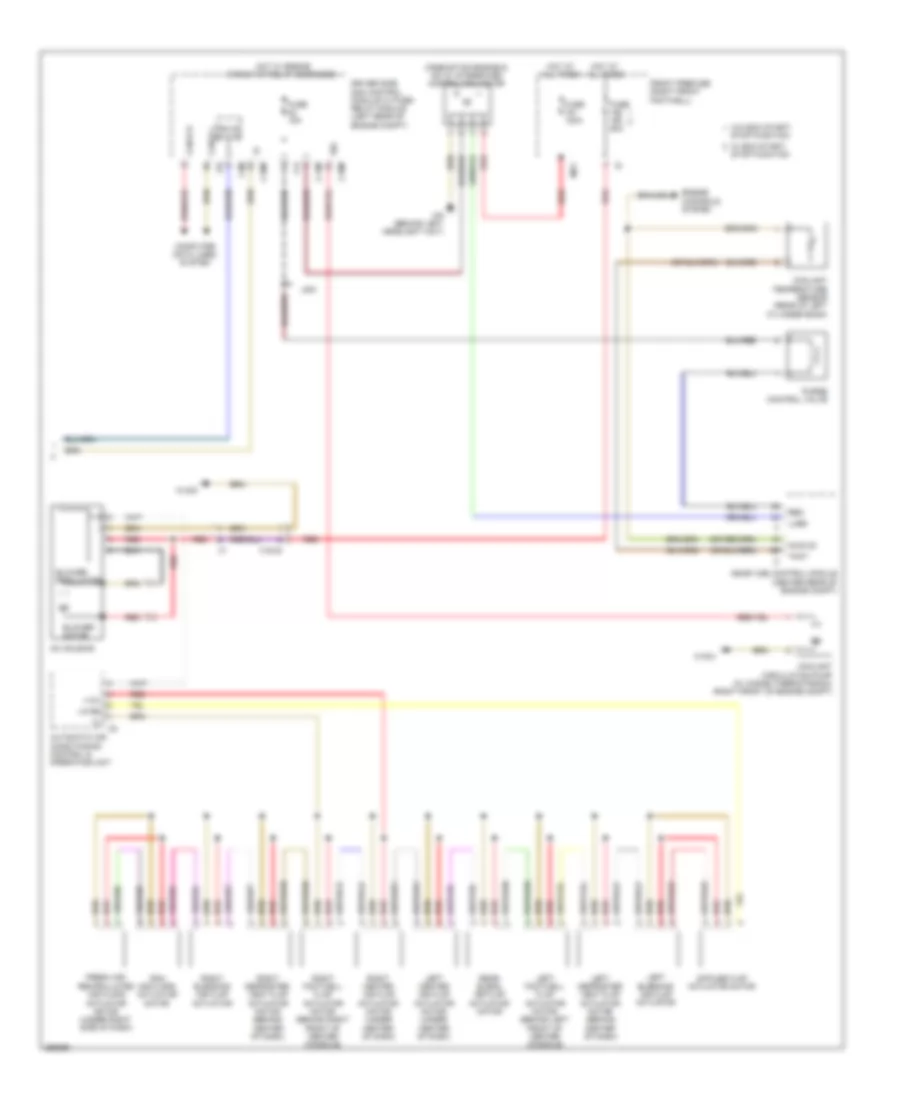
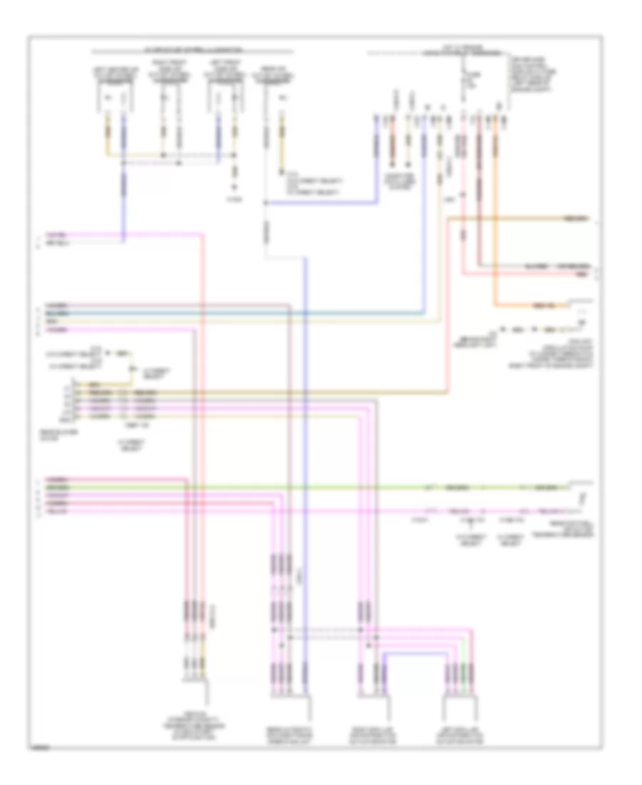
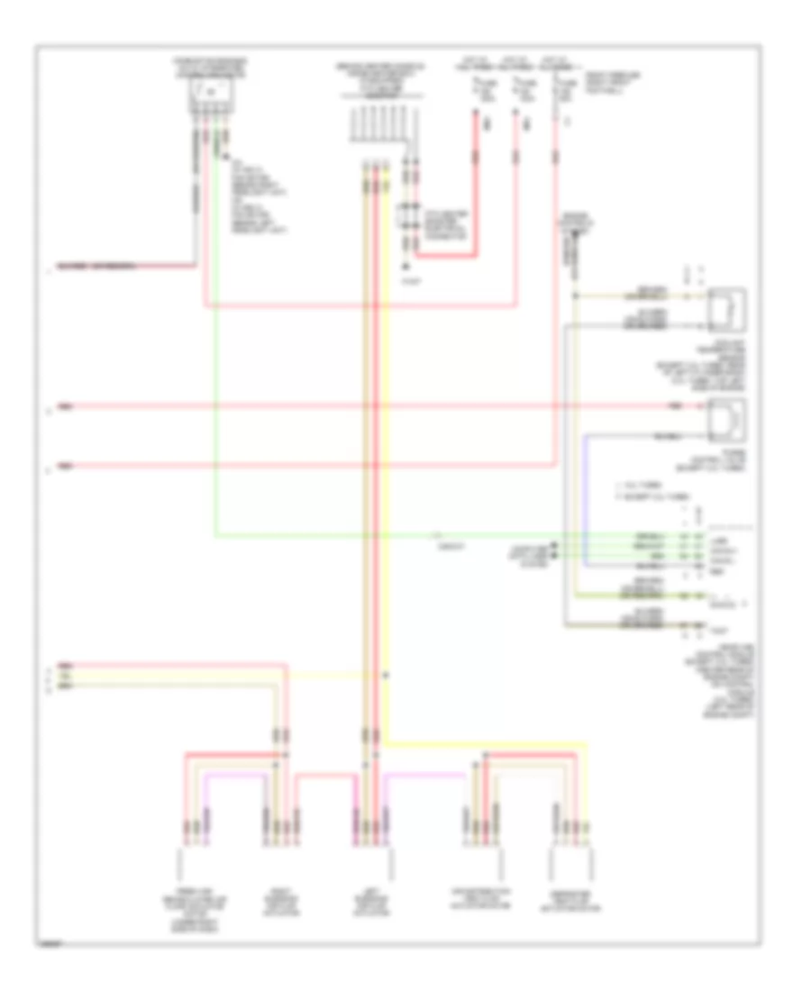
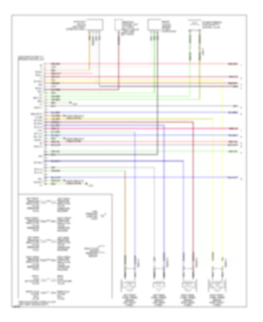
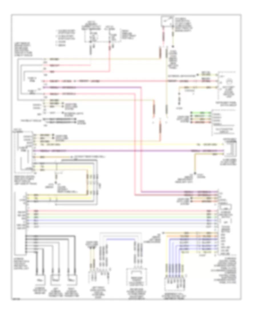
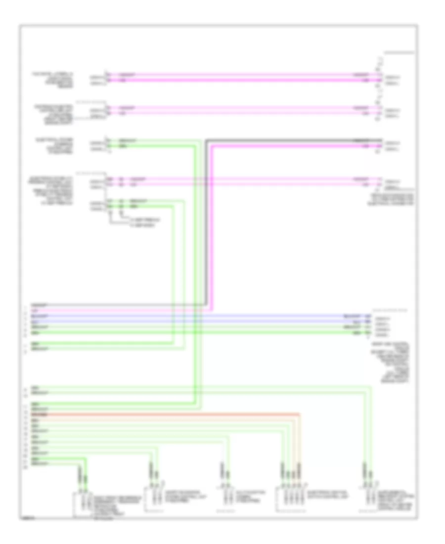
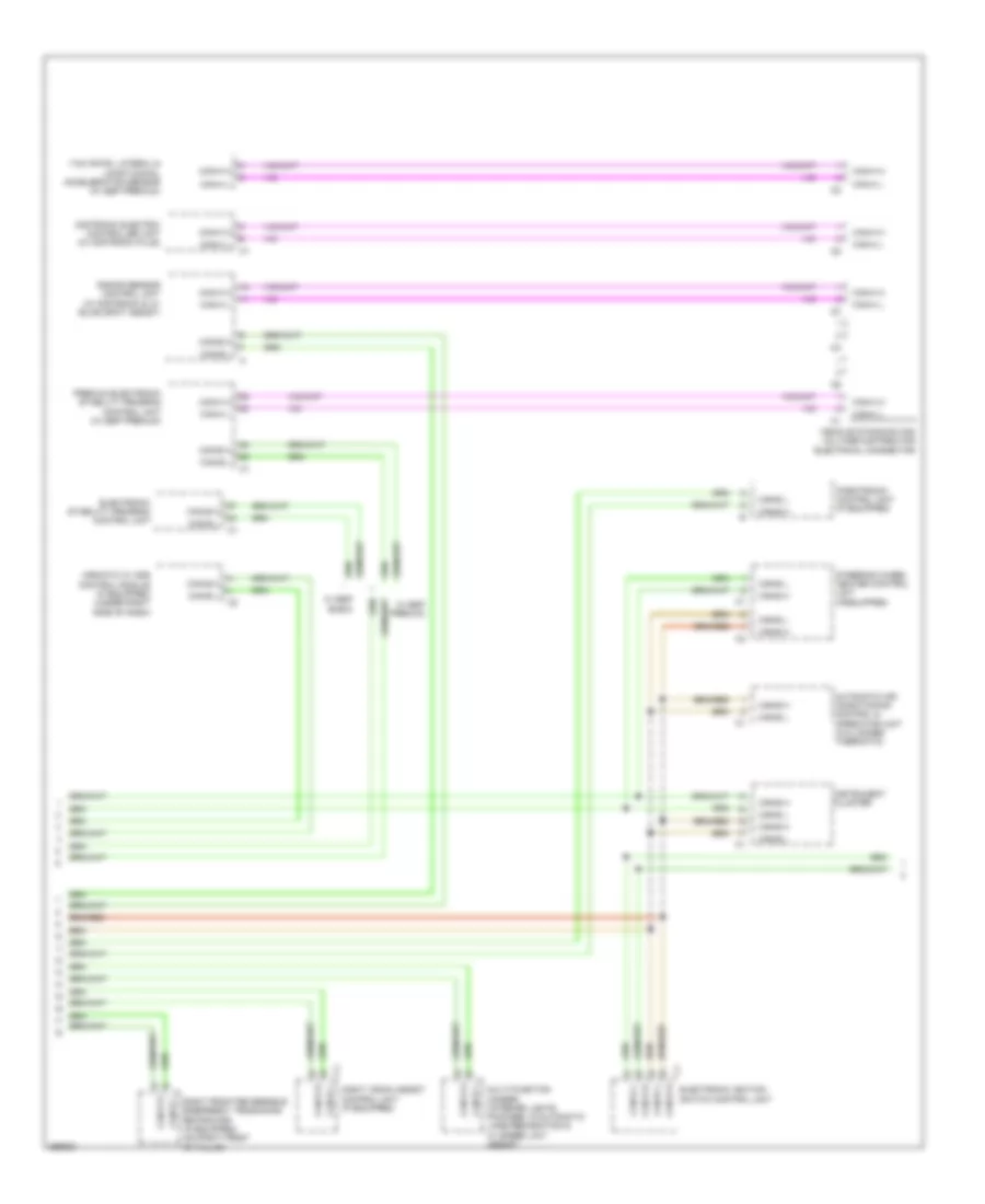
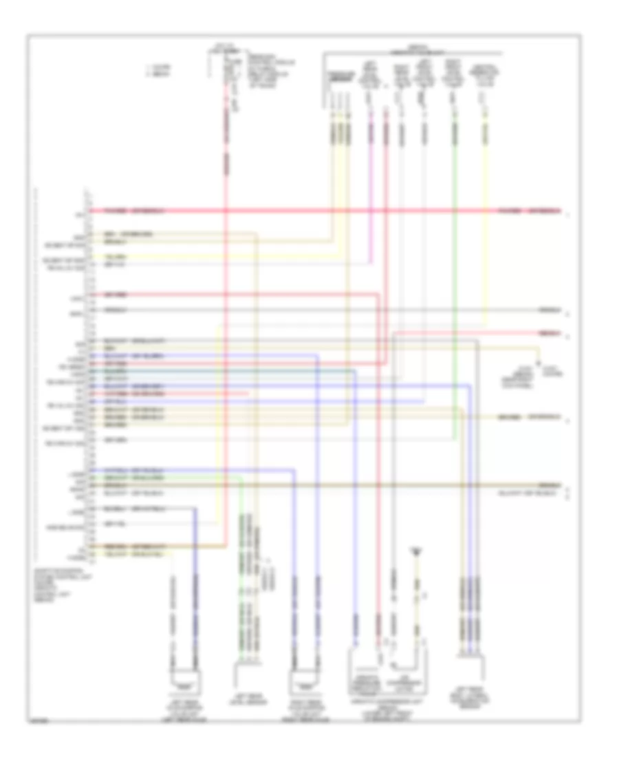
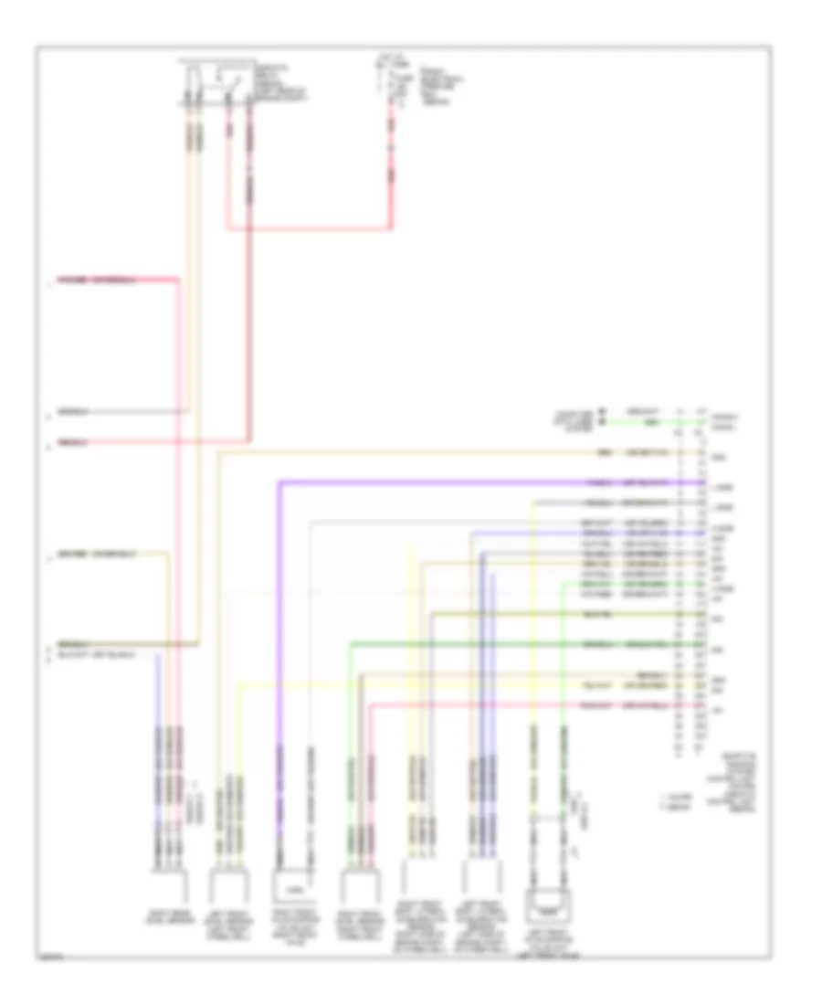
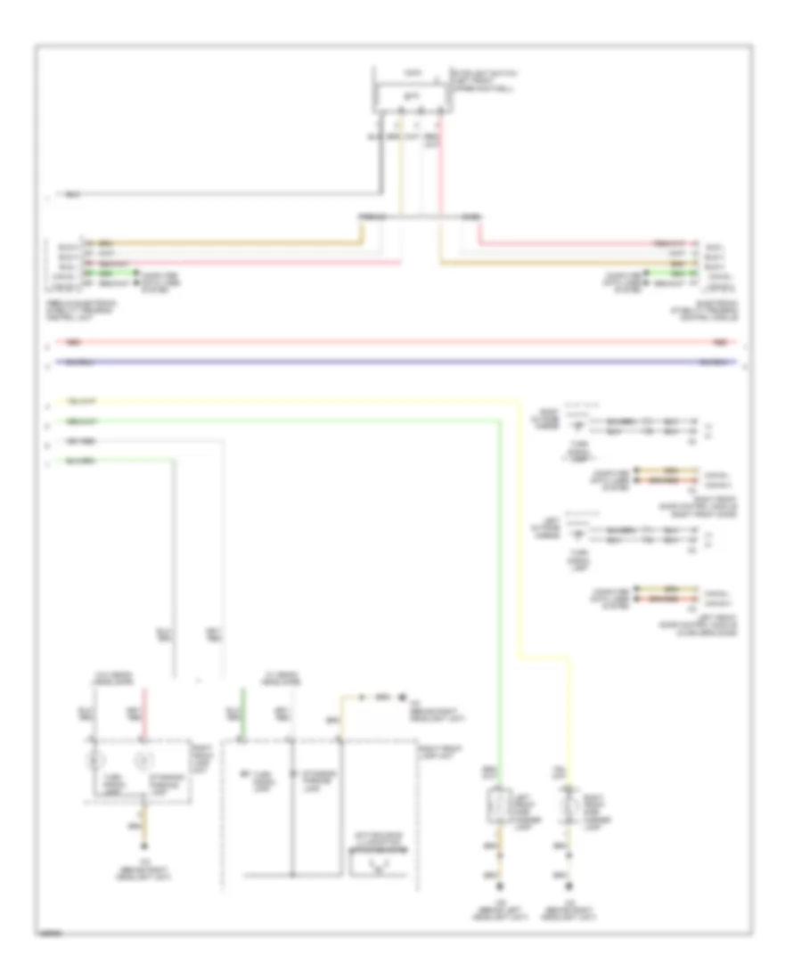
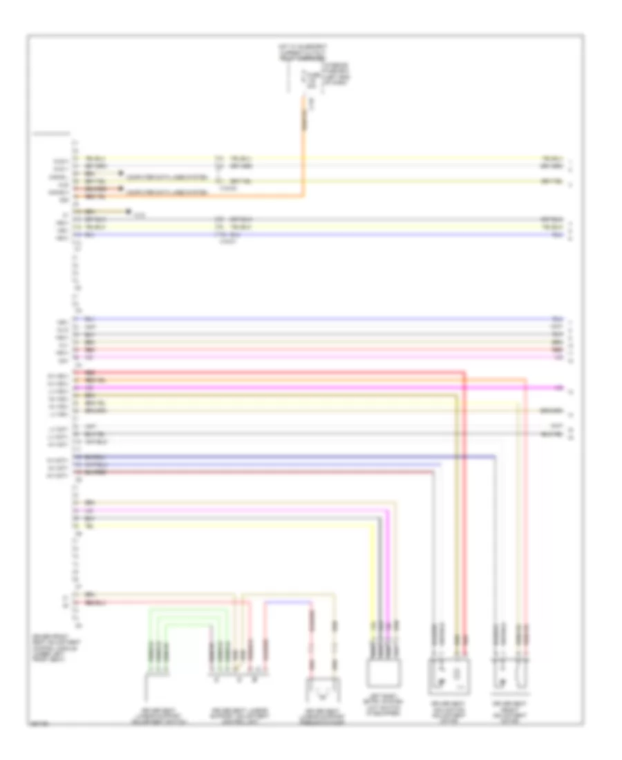
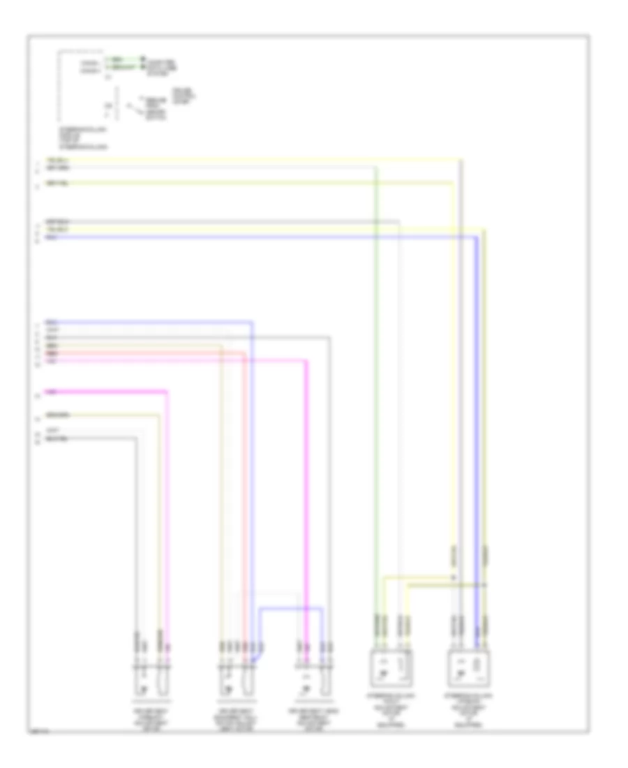
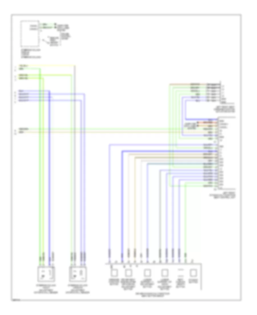
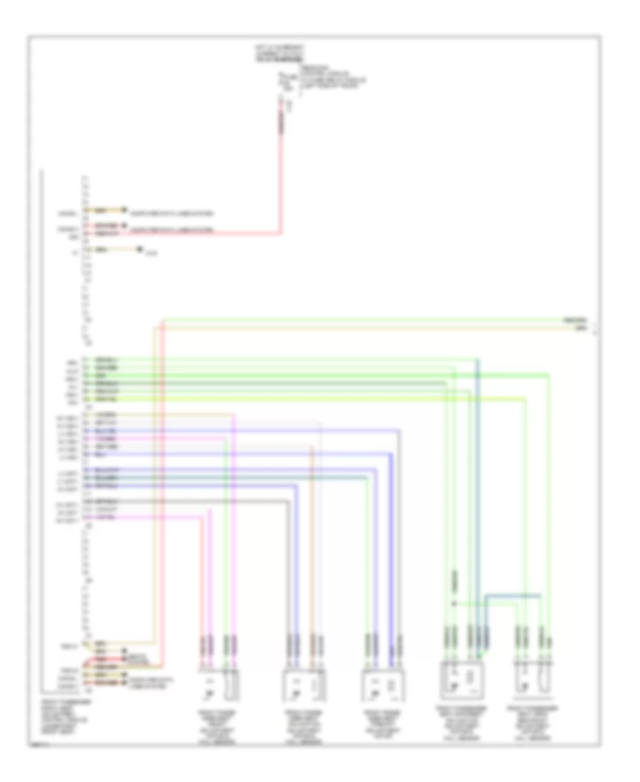
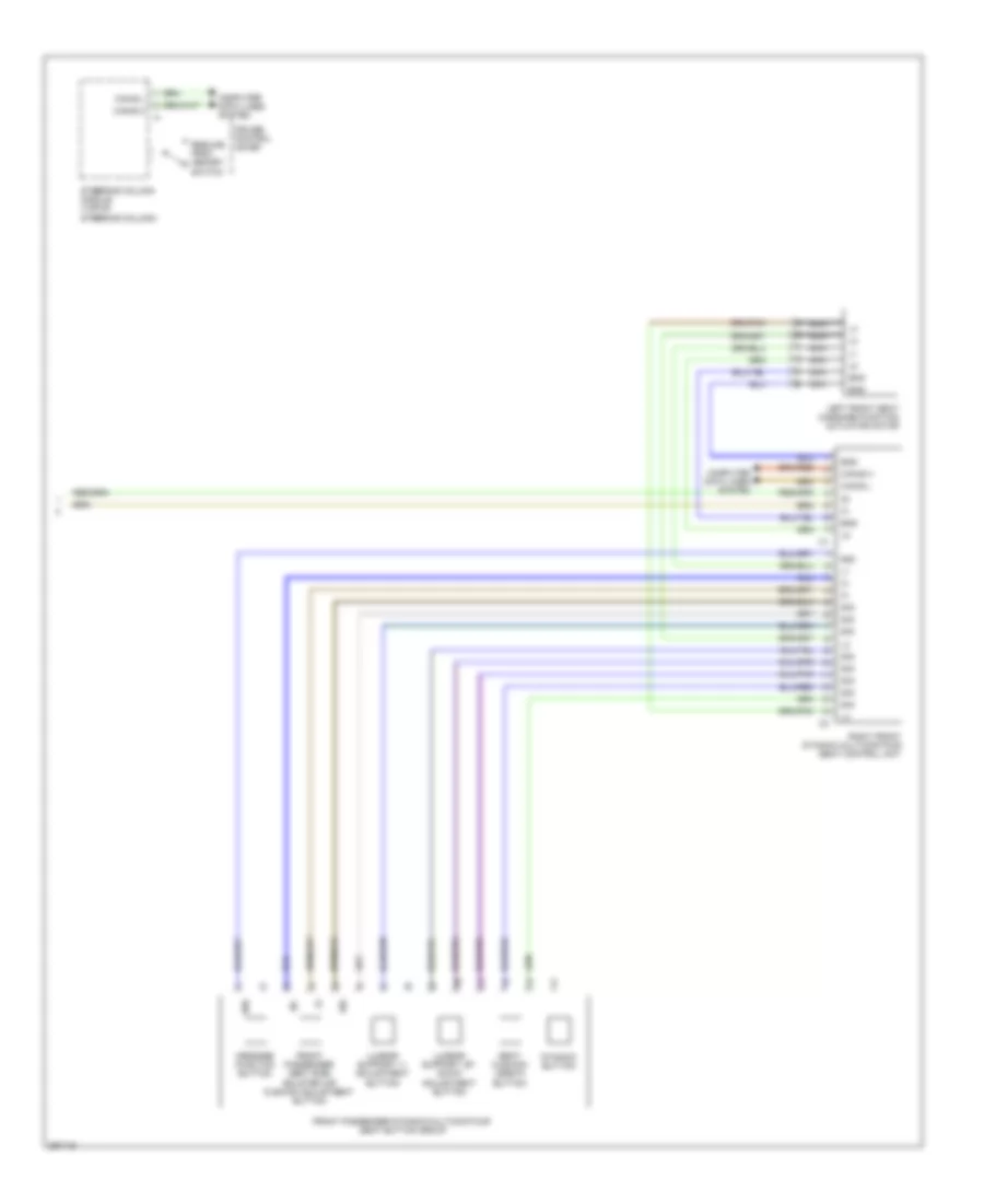
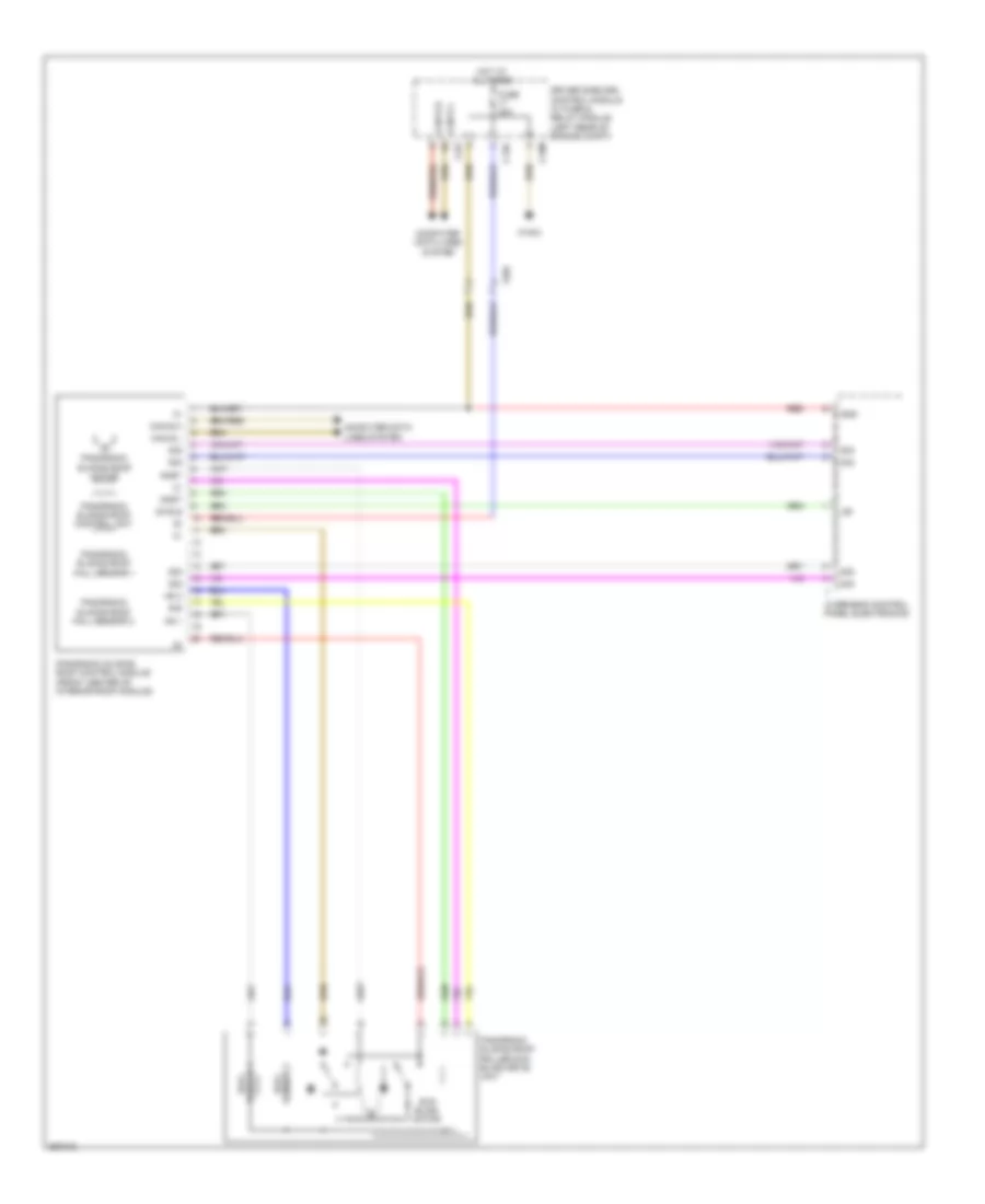
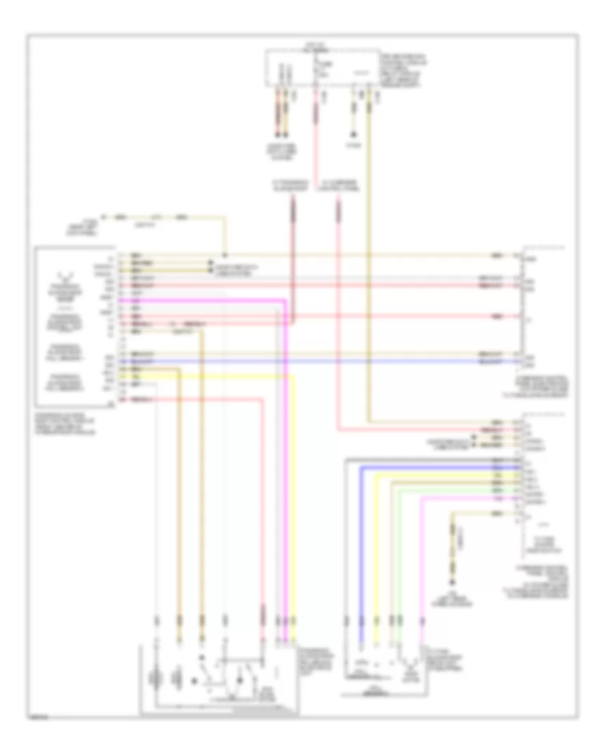
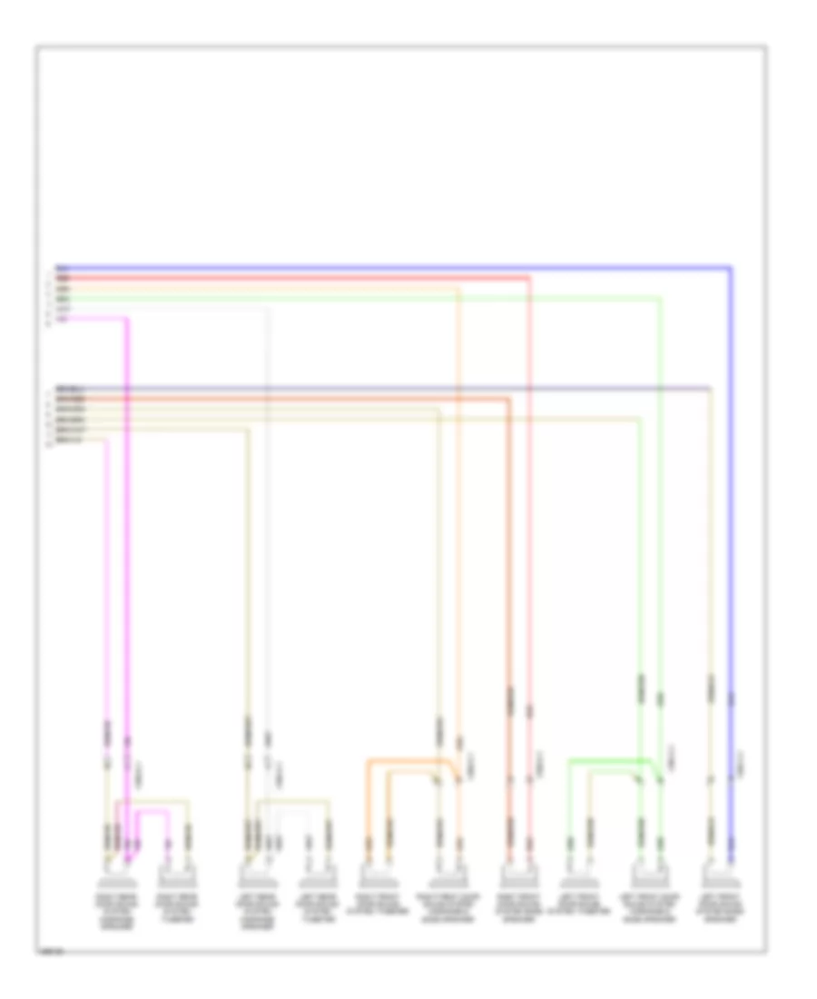
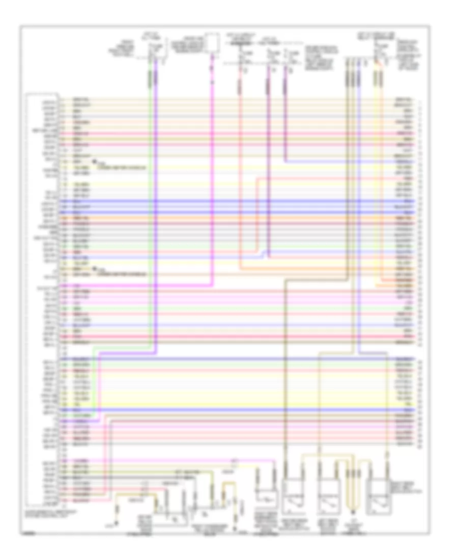
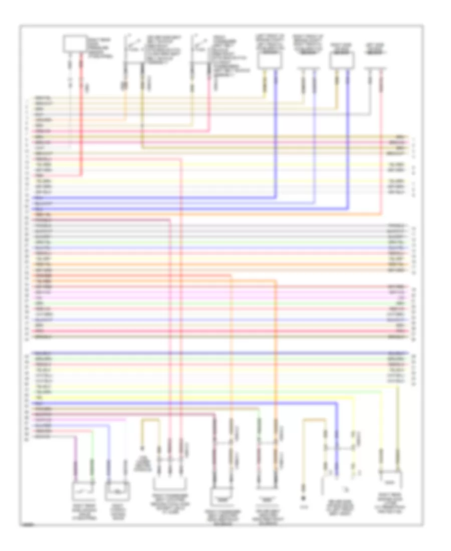
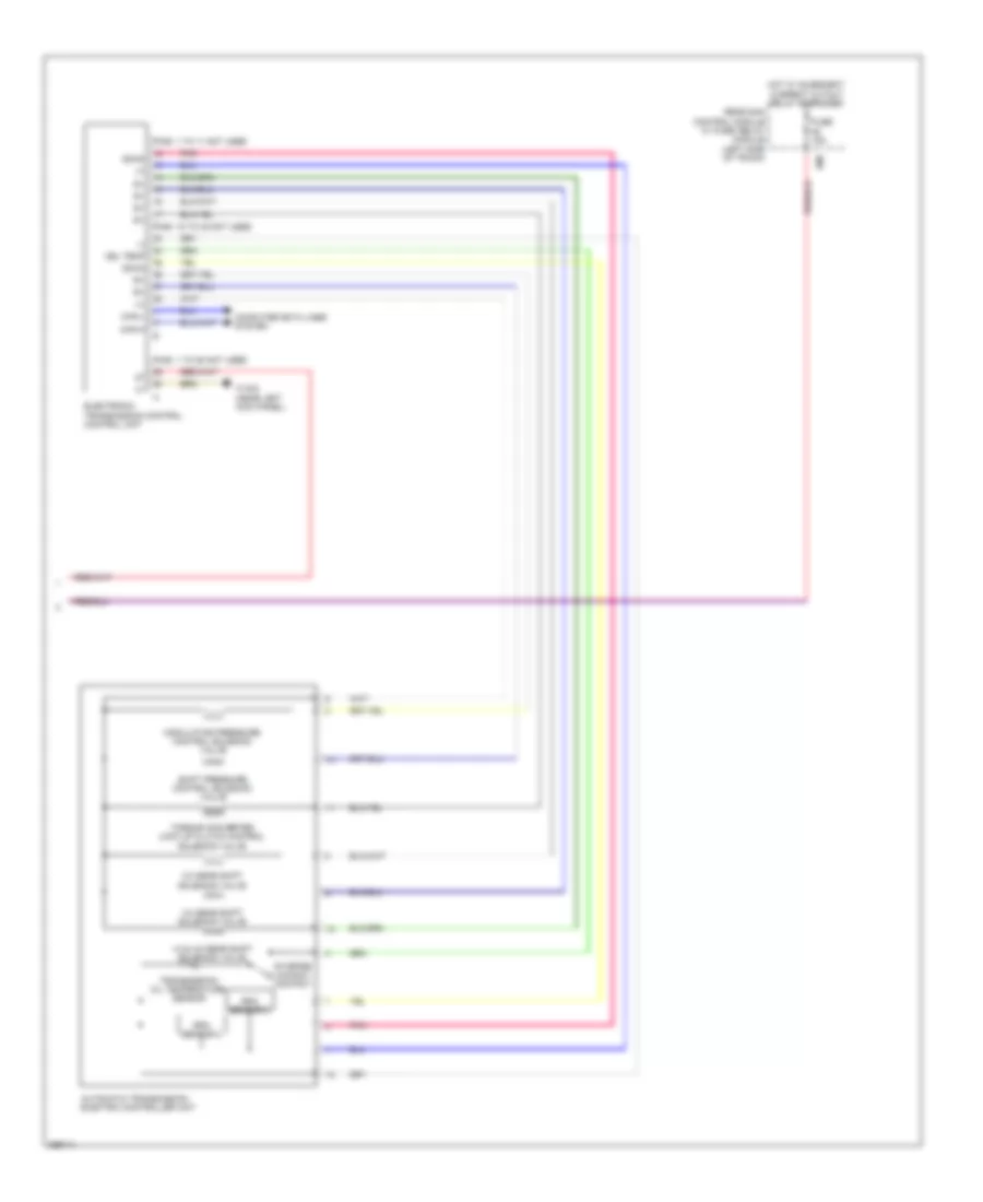
Automatic A/C Wiring Diagram, Coupe with Thermotronic (2 of 2) for Mercedes-Benz E350 2011
List of elements for Automatic A/C Wiring Diagram, Coupe with Thermotronic (2 of 2) for Mercedes-Benz E350 2011:
- +12v
- 22i
- Ac housing
- Automatic air conditioning control & operating unit
- Blower motor
- Blower regulator
- C14m
- C18m
- C3m
- C4i
- Can-b h
- Can-b l
- Combustion engine & a/c w/ integrated control fan motor
- Computer data lines system
- Coolant circulation pump (w/ 3-zone thermotronic) (right front of engine compt)
- Coolant temperature sensor (rear of left cylinder bank)
- Diffuse flap actuator motor
- Driver side sam control module w/ fuse/ relay module (left rear of engine compt)
- Engine controls system
- Fresh air/ recirculated air flaps actuator motor (under right side of dash)
- Front prefuse (right front footwell)
- Fuse 100a
- Fuse 15a
- Fuse 50a
- Hot at all times
- Hot w/ engine circuit 87 relay energized
- Left blending air flap actuator
- Left center air flap actuator motor (under center of dash)
- Left defroster vent flap actuator motor (behind center of dash)
- Left footwell flap actuator motor (behind left front of center console)
- Lin b8
- Lues
- Me-sfi (me) control module (center rear of engine compt)
- Mr1
- Nwg m2
- Purge control valve
- Ram air flaps actuator motor
- Rear blend air flap actuator motor
- Red
- Reg
- Right blending air flap actuator
- Right center air flap actuator motor (under center of dash)
- Right defroster vent flap actuator motor (behind center of dash)
- Right footwell flap actuator motor (behind right front of center console)
- Sig
- Solid state
- Stop function
- Tmot
- Usa
- W/ eco start/ stop function
- W/o eco start/
- W15/5
- W16/4
- W9 (behind left headlight unit)
- X18/40
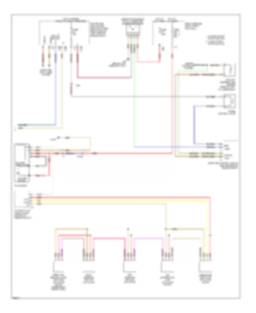
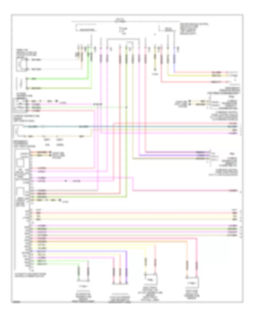
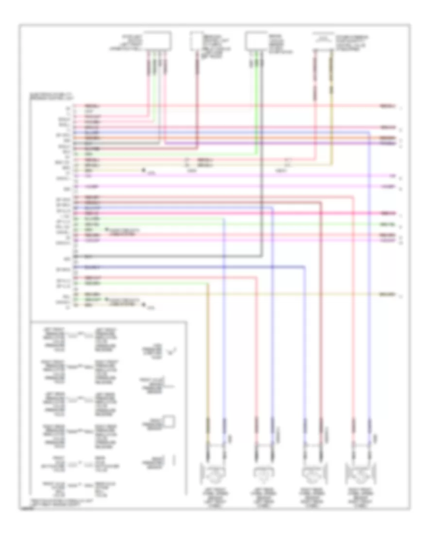
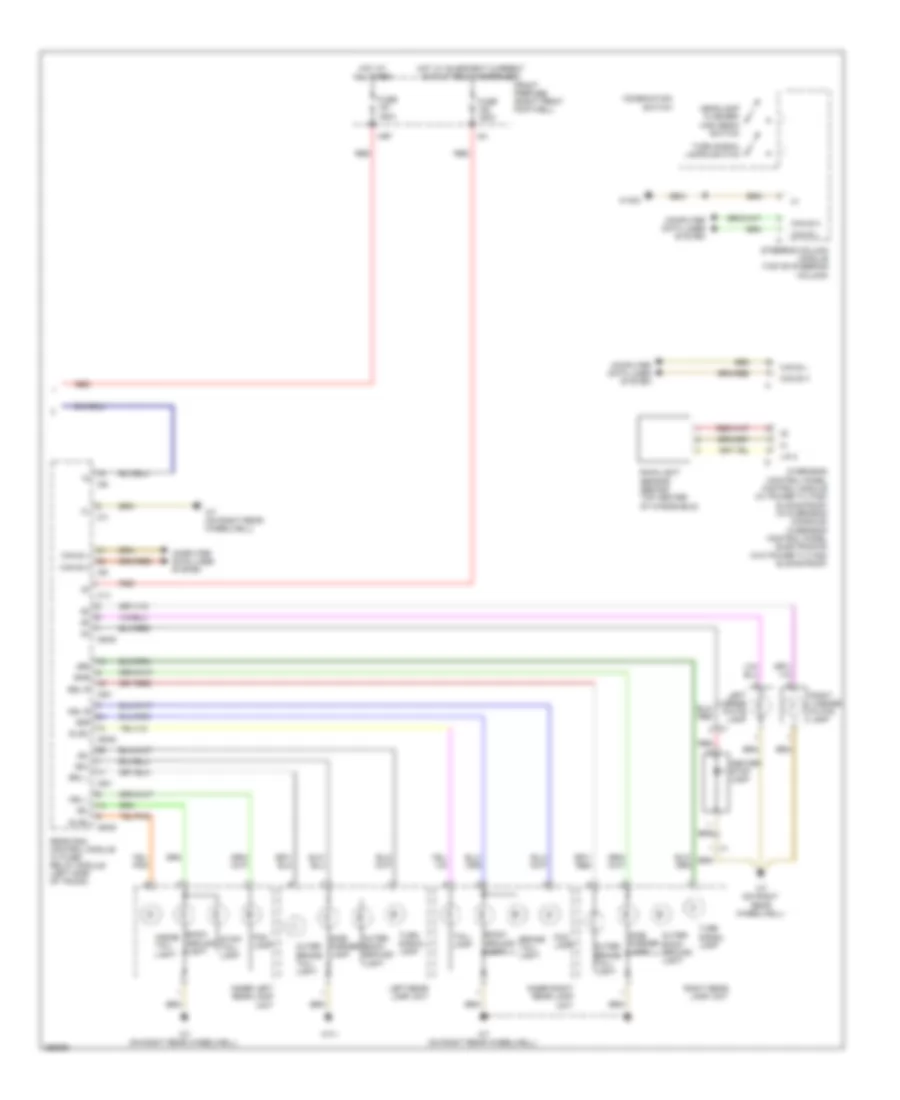
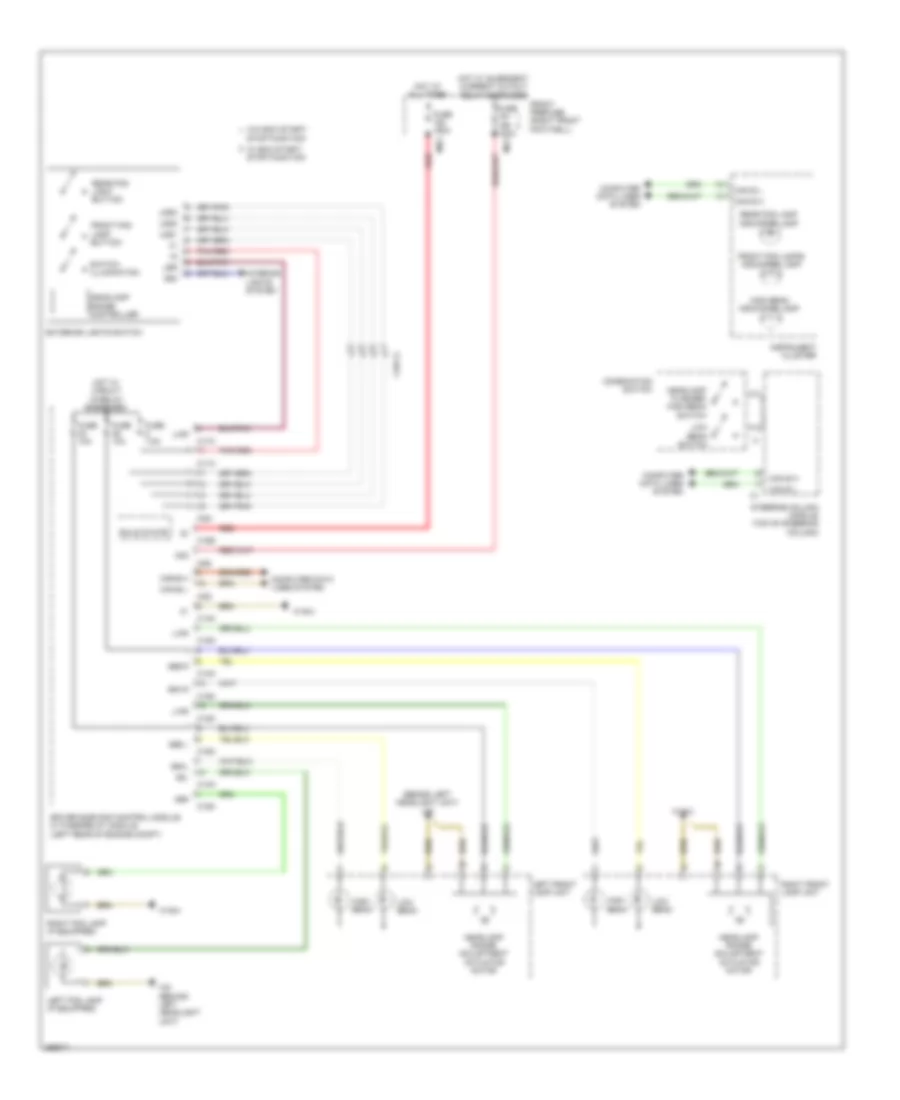
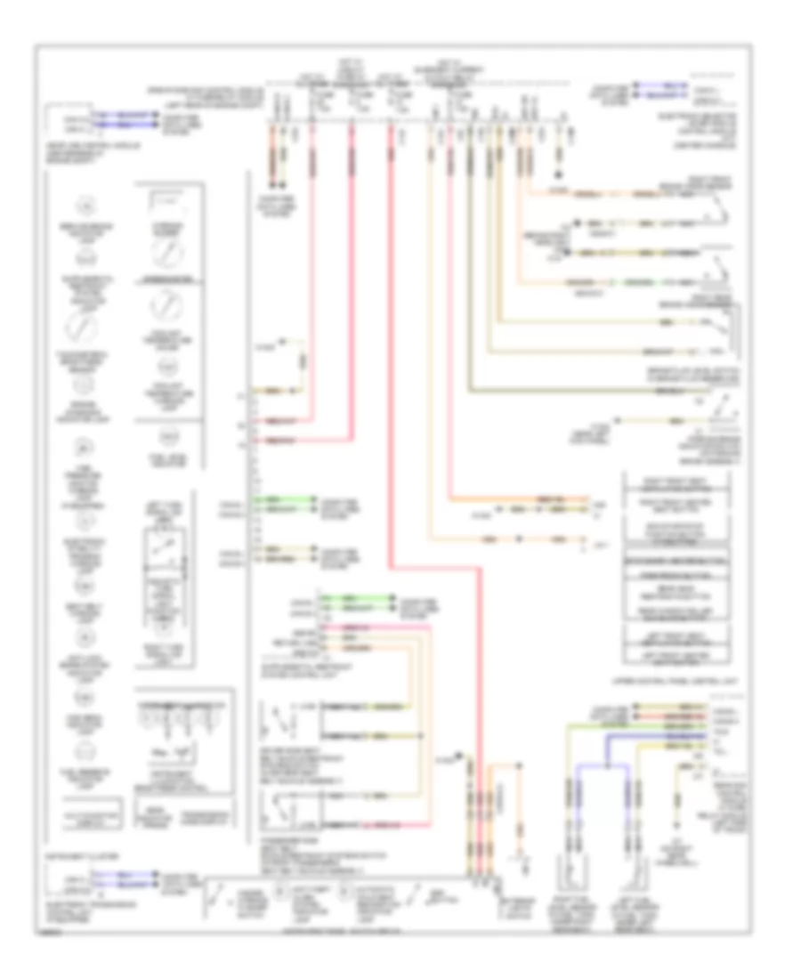
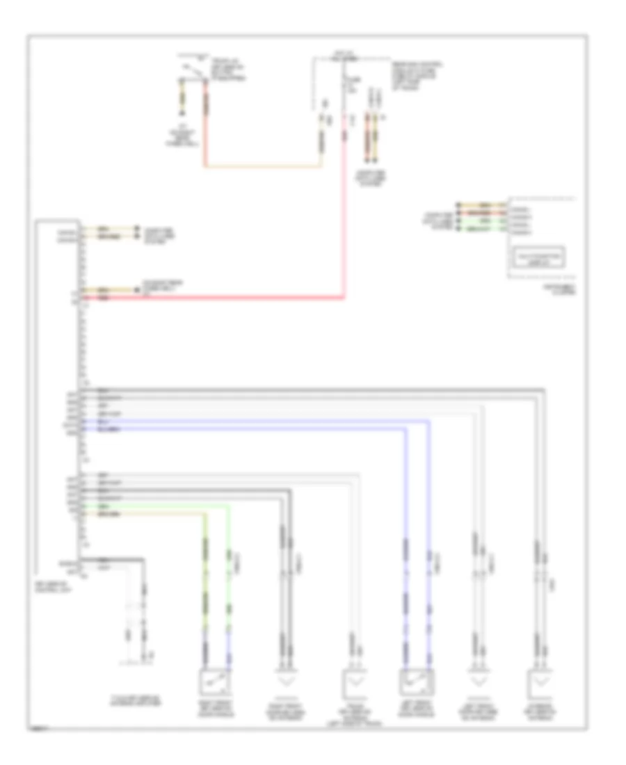
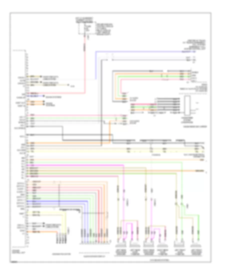
Automatic A/C Wiring Diagram, Coupe without Thermotronic (1 of 2) for Mercedes-Benz E350 2011
List of elements for Automatic A/C Wiring Diagram, Coupe without Thermotronic (1 of 2) for Mercedes-Benz E350 2011:
- (+)
- 12v
- 30g
- Air recir- culation mode button
- Automatic air conditioning control & operating unit
- C-aac sun sensor (center rear of engine compt hood)
- C11c
- C13d
- C14m
- C17c
- C21m
- C5c
- C7i
- Can-b h
- Can-b l
- Computer data lines system
- Driver side sam control module w/ fuse/ relay module (left rear of engine compt)
- Evaporator temperature sensor (right side of dash)
- Fuse 7.5a
- Gnd
- Hot at all times
- Interior humidity/ temperature sensor (if equipped)
- Interior temperature sensor (left side of dash)
- Interior temperature sensor w/ integrated fan
- Left center air outlet symbol illumination (if equipped)
- Left front footwell air outlet temperature sensor (left front footwell area)
- Left front side air outlet symbol illumination (if equipped)
- Left side air outlet temperature sensor
- Lin data
- Nca
- Outside temperature sensor
- Overhead control panel electronics (w/o can)
- Rear air outlet symbol illumination (if equipped)
- Rear window heater button
- Refrigerant compressor (left front engine)
- Refrigerant pressure sensor (left front of engine compt)
- Right center air outlet symbol illumination (if equipped)
- Right front footwell air outlet temperature sensor (right front footwell area)
- Right front side air outlet symbol illumination (if equipped)
- Right side air outlet temperature sensor
- Sig
- Solid state
- W15/5
- W16/3
- X15/12
- X18/35-c1
- X226
- X26-c1
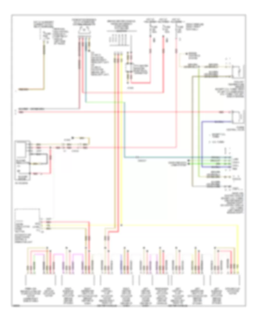
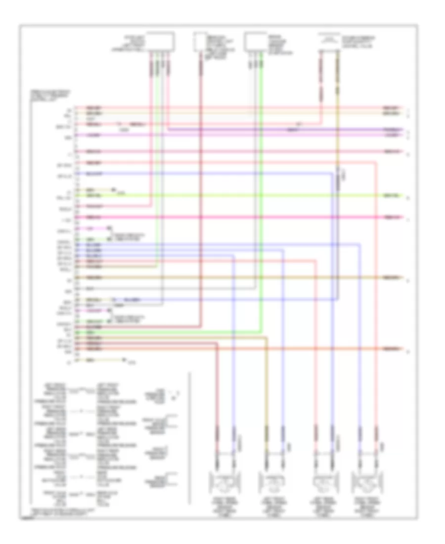
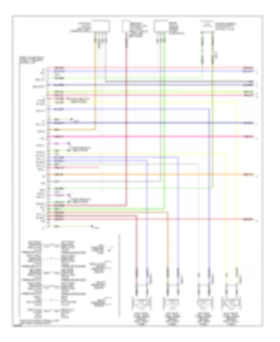
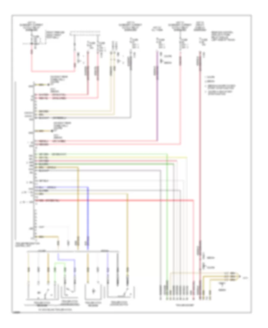
Automatic A/C Wiring Diagram, Coupe without Thermotronic (2 of 2) for Mercedes-Benz E350 2011
List of elements for Automatic A/C Wiring Diagram, Coupe without Thermotronic (2 of 2) for Mercedes-Benz E350 2011:
- +12v
- 22i
- Ac housing
- Air distribution flap actuator motor
- Automatic air conditioning control & operating unit
- Blower motor
- Blower regulator
- C14m
- C18m
- C3m
- C4i
- Can-b h
- Can-b l
- Combustion engine & a/c w/ integrated control fan motor
- Computer data lines system
- Coolant temperature sensor (rear of left cylinder bank)
- Defroster vent flap actuator motor
- Driver side sam control module w/ fuse/ relay module (left rear of engine compt)
- Engine controls system
- Fresh air/ recirculated air flaps actuator motor (under right side of dash)
- Front prefuse (right front footwell)
- Fuse 100a
- Fuse 15a
- Fuse 50a
- Hot at all times
- Hot w/ engine circuit 87 relay energized
- Left blending air flap actuator
- Lin b
- Lues
- Me-sfi (me) control module (center rear of engine compt)
- Mr1
- Nwg m2
- Purge control valve
- Red
- Reg
- Right blending air flap actuator
- Solid state
- Stop function
- Tmot
- Usa
- W/ eco start/ stop function
- W/o eco start/
- W15/5
- W9 (behind left headlight unit)
- X18/40
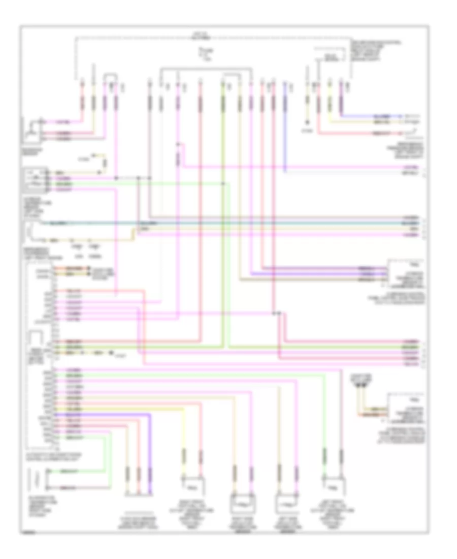
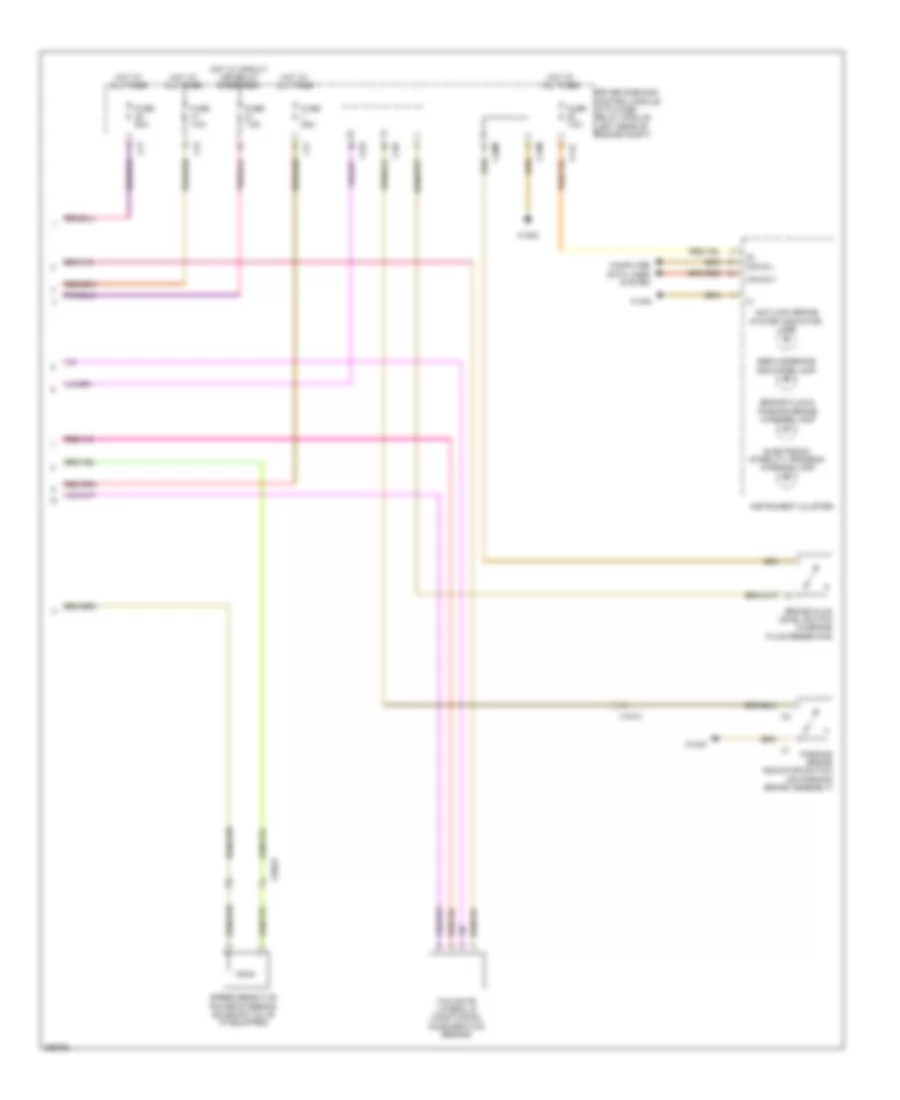
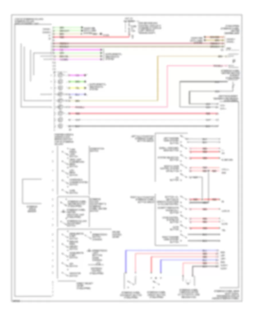
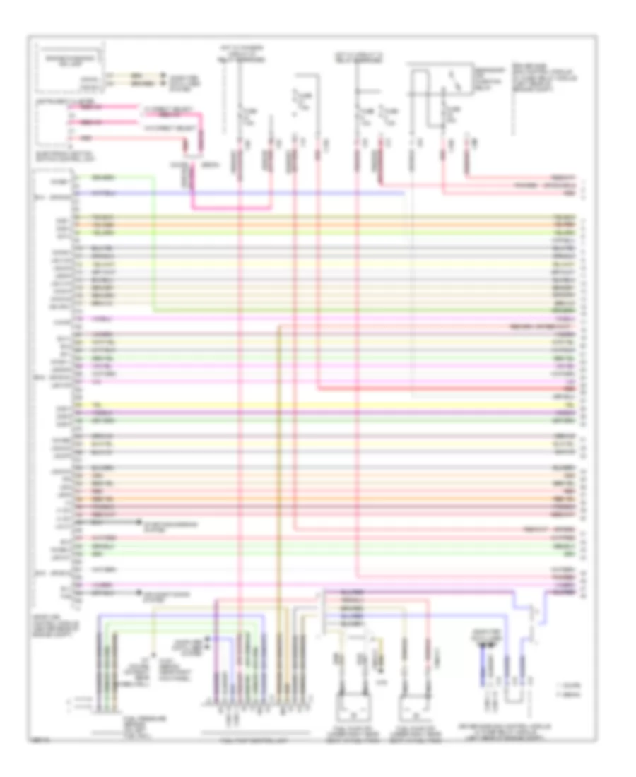
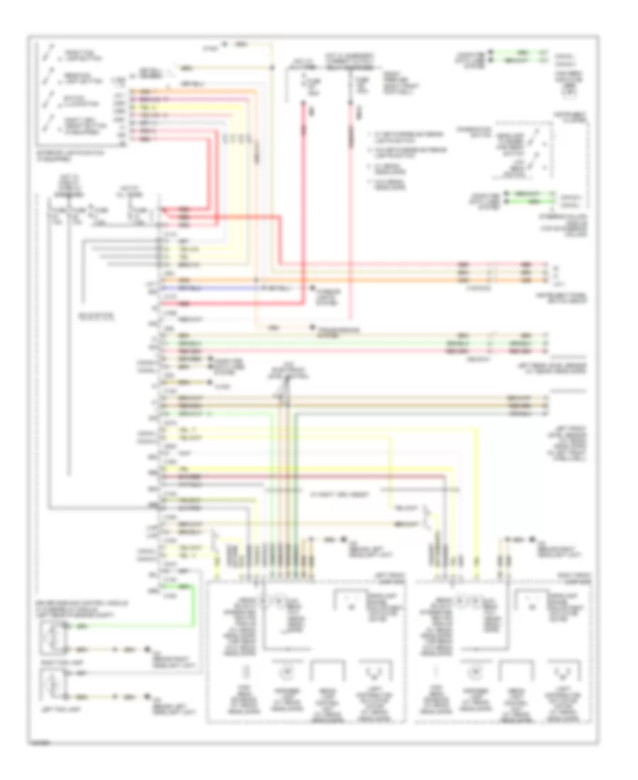
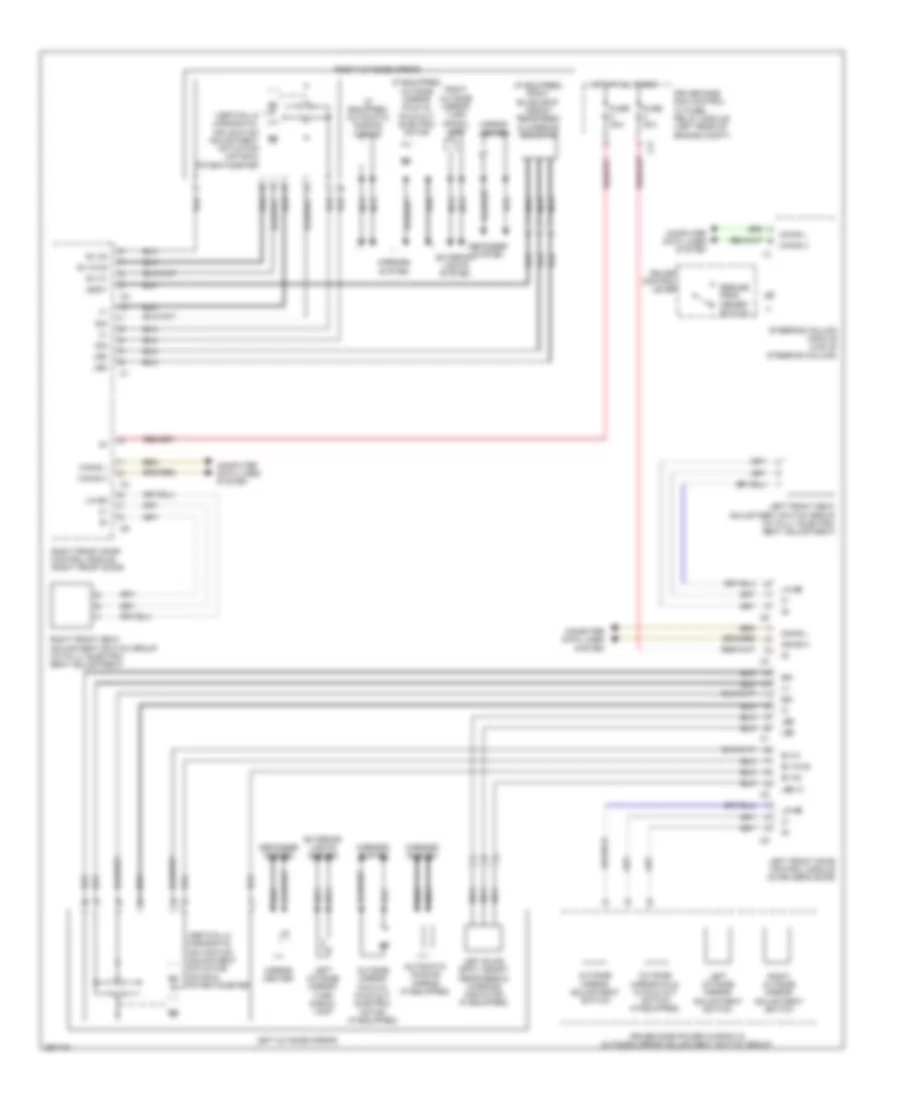
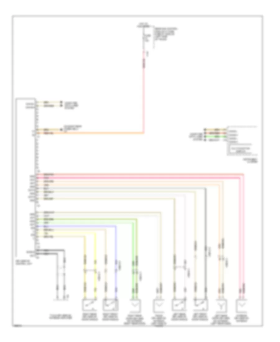
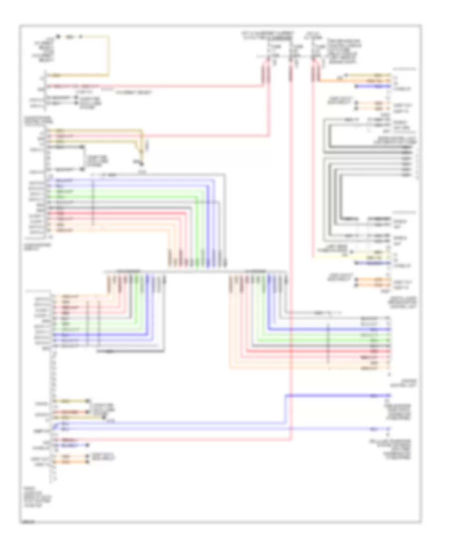
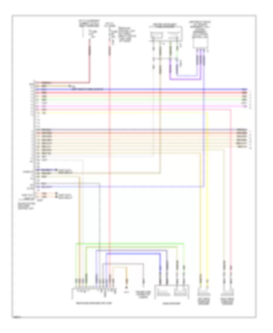
Automatic A/C Wiring Diagram, Sedan with Thermotronic (1 of 3) for Mercedes-Benz E350 2011
List of elements for Automatic A/C Wiring Diagram, Sedan with Thermotronic (1 of 3) for Mercedes-Benz E350 2011:
- Automatic air conditioning control & operating unit
- C-aac sun sensor (center rear of engine compt hood)
- C13d
- C14m
- C17c
- C18m
- C21m
- C5c
- Can-b h
- Can-b l
- Computer data lines system
- Diesel
- Driver side sam control module w/ fuse/ relay module (left rear of engine compt)
- Emissions sensor
- Evaporator temperature sensor (right side of dash)
- Fuse 7.5a
- Gas
- Gnd
- Hot at all times
- Interior temperature sensor (left side of dash)
- Interior temperature sensor w/ integrated fan
- Left front footwell air outlet temperature sensor (right front footwell area)
- Left side air outlet temperature sensor
- Lin
- Lin data
- Overhead control panel control electronics (w/o tilting/sliding roof)
- Overhead control panel control module (in overhead console) (w/ tilting/sliding roof)
- Rear window heater button
- Refrigerant compressor (left front engine)
- Refrigerant pressure sensor (left front of engine compt)
- Right front footwell air outlet temperature sensor (right front footwell area)
- Right side air outlet temperature sensor
- Sig
- Sig li
- Sig re
- Solid state
- W15/5
- W15/7
- X26-c1
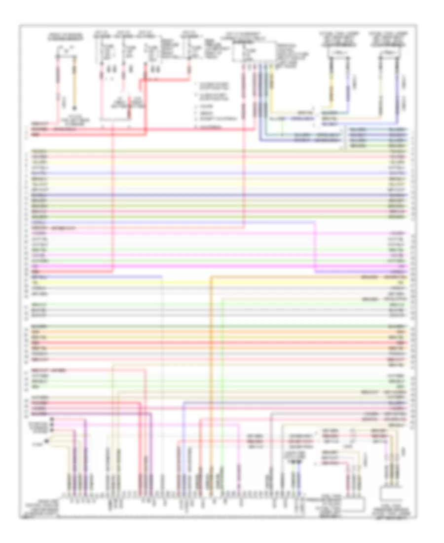
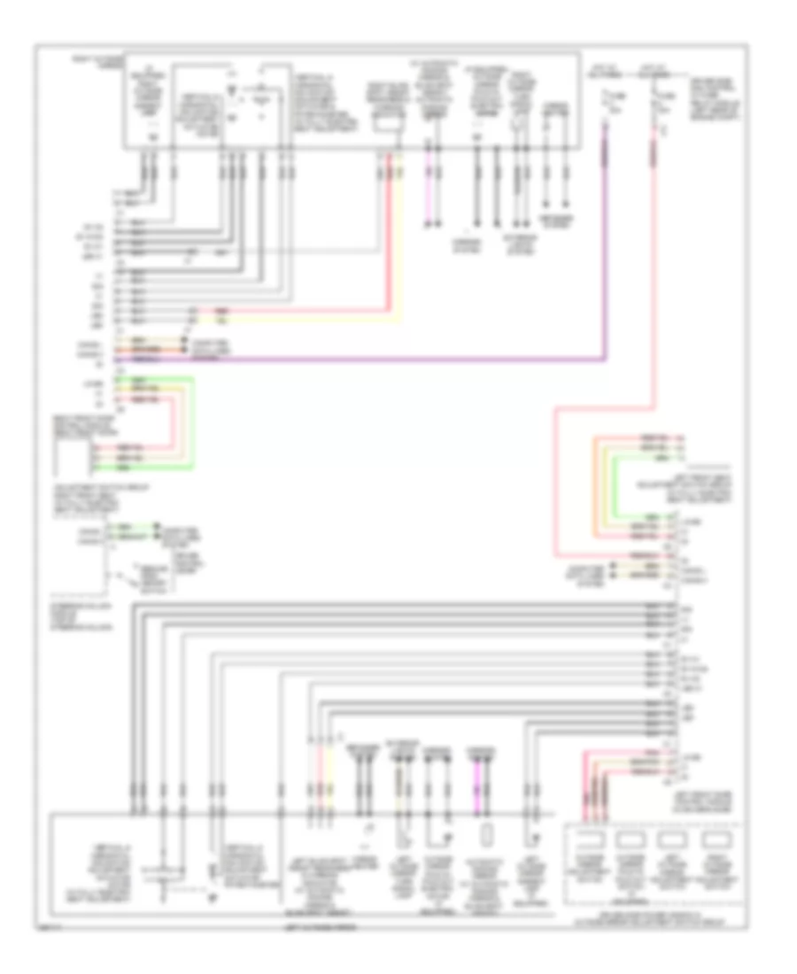
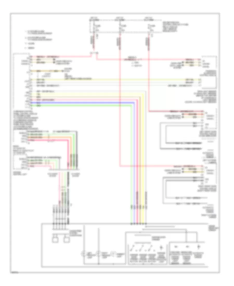
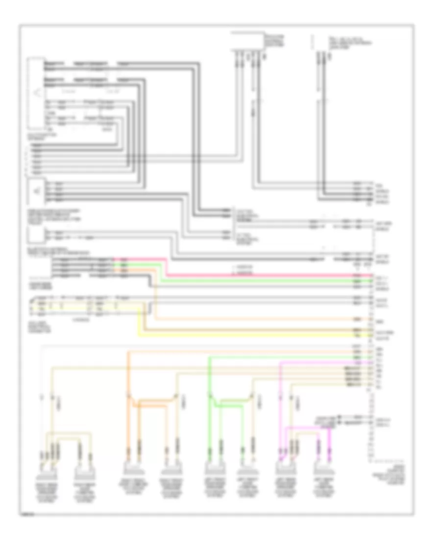
Automatic A/C Wiring Diagram, Sedan with Thermotronic (2 of 3) for Mercedes-Benz E350 2011
List of elements for Automatic A/C Wiring Diagram, Sedan with Thermotronic (2 of 3) for Mercedes-Benz E350 2011:
- C14m
- C18m
- C19i
- C22i
- C3m
- C4i
- Can-b h
- Can-b l
- Computer data lines system
- Coolant circulation pump (w/ 2-zone thermatic & 3-zone thermotronic) (right front of engine compt)
- Driver side sam control module w/ fuse/ relay module (left rear of engine compt)
- Fuse 15a
- Gnd
- Hot w/ engine circuit 87 relay energized
- Left b-pillar air distribution actuator motor
- Left center air outlet symbol illumination
- Left front side air outlet symbol illumination
- Lin
- Rear air outlet symbol illumination
- Rear automatic air conditioning operating unit
- Rear blower motor
- Rear footwell air outlet temperature sensor
- Red
- Right b-pillar air distribution actuator motor
- Right front side air outlet symbol illumination
- Sig
- Usa
- Vehicle interior humidity/ temperature sensor (w/ eco start/ stop function)
- W/ air outlet symbol illumination
- W/ direct select
- W/o direct select
- W15/5
- W18 (w/o direct select) w19 (w/ direct select)
- W2 (behind right headlight unit)
- X138/1-c2
- X138/1-c3
- X18-c1
- X25/2-c1
- X83/11-c2
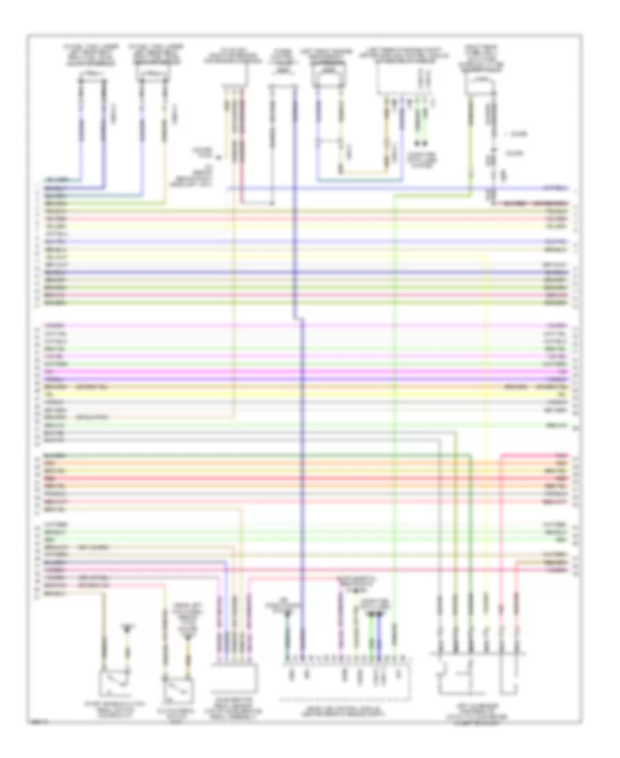
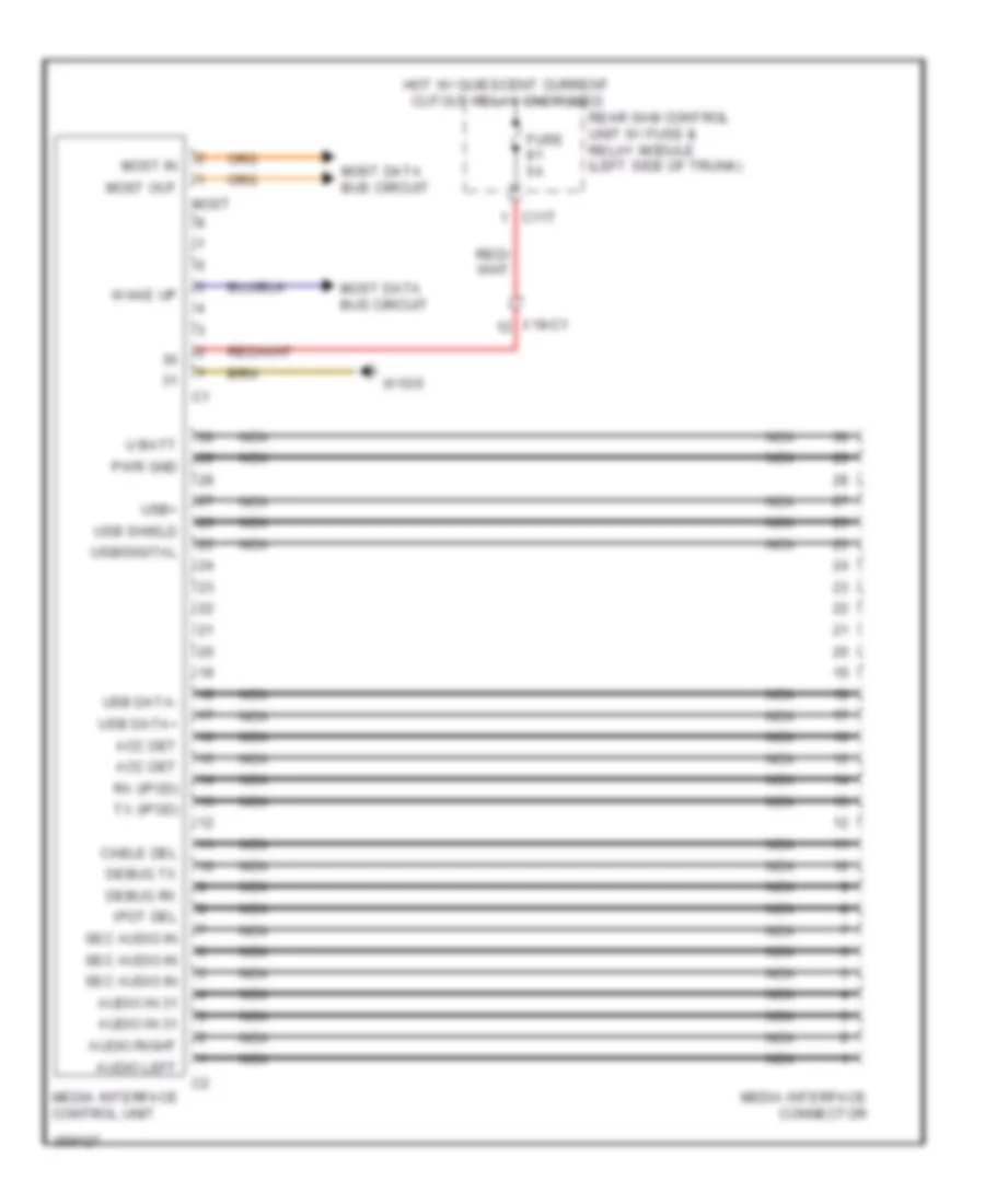
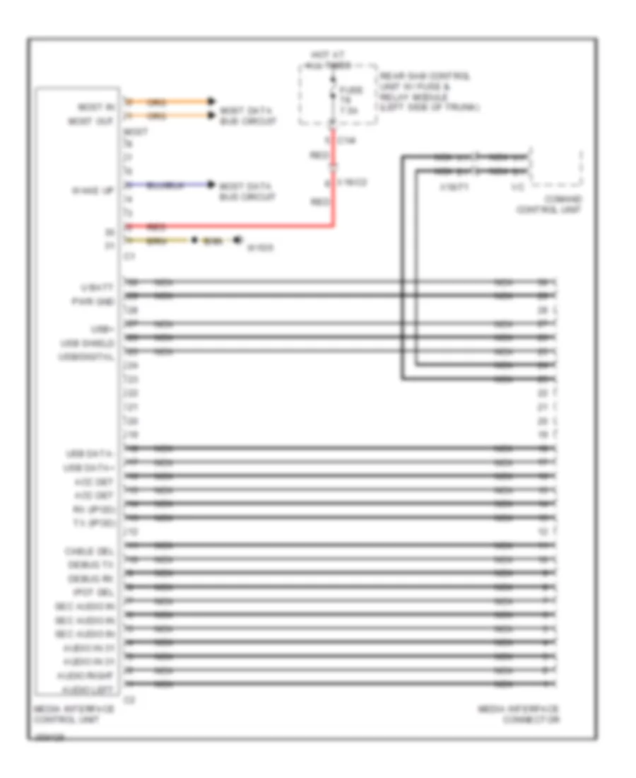
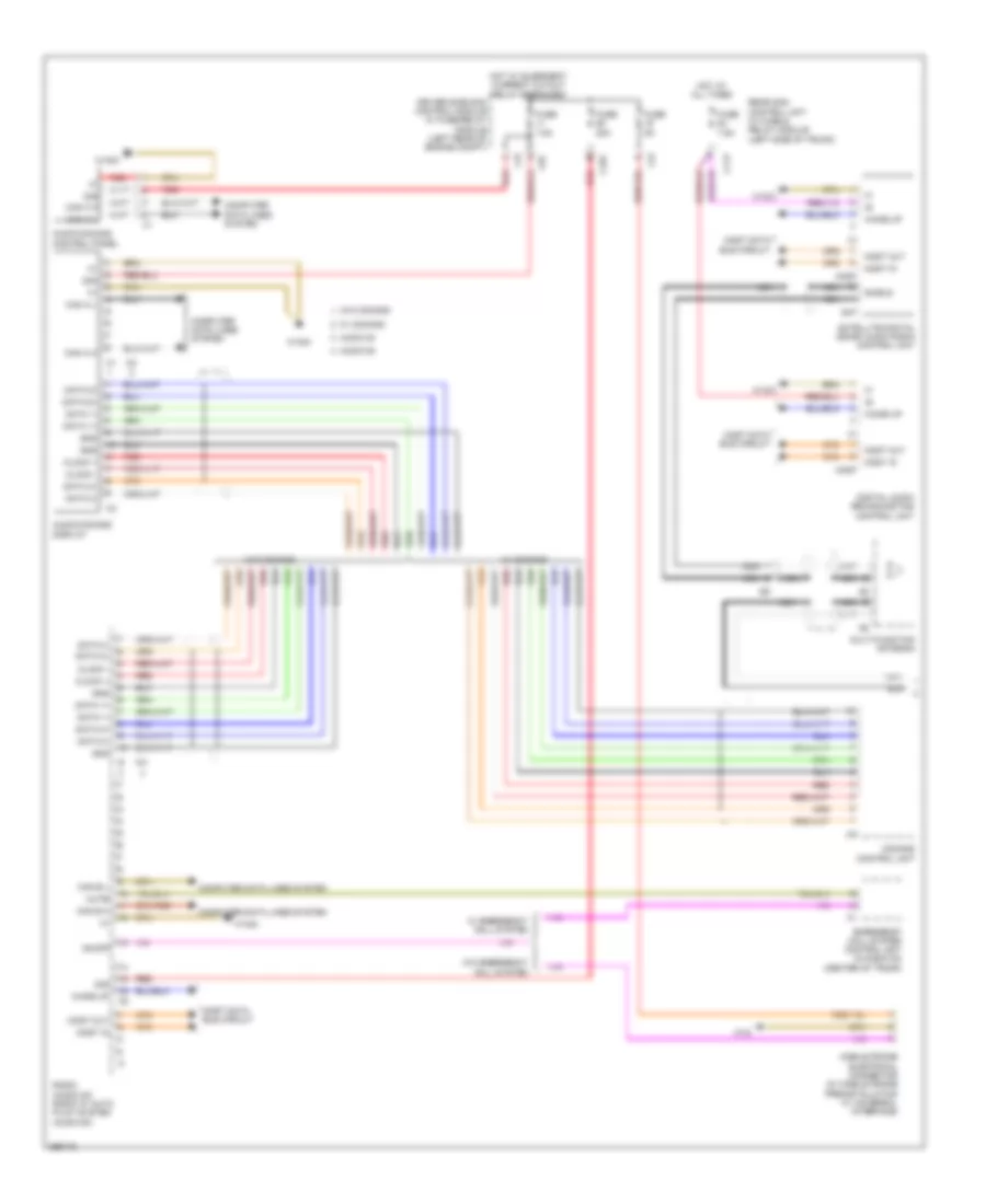
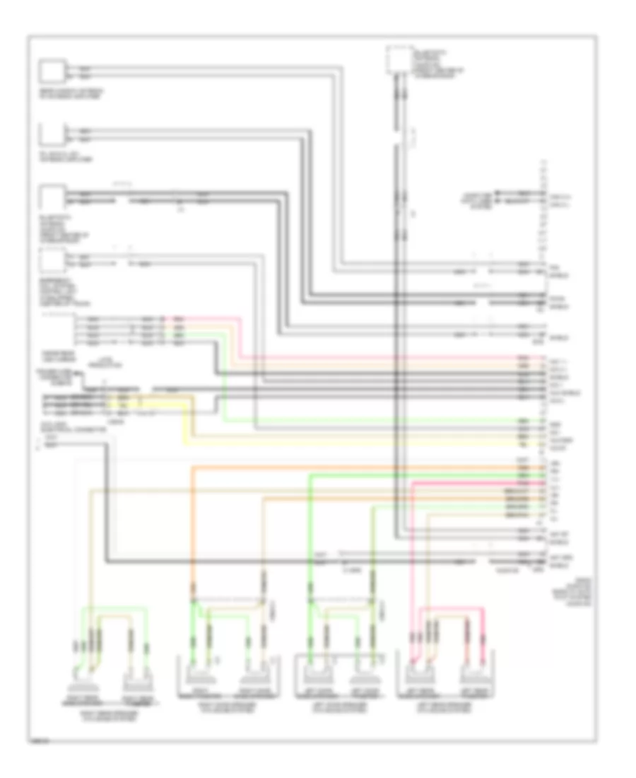
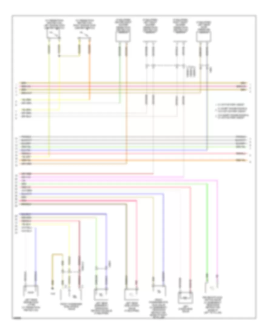
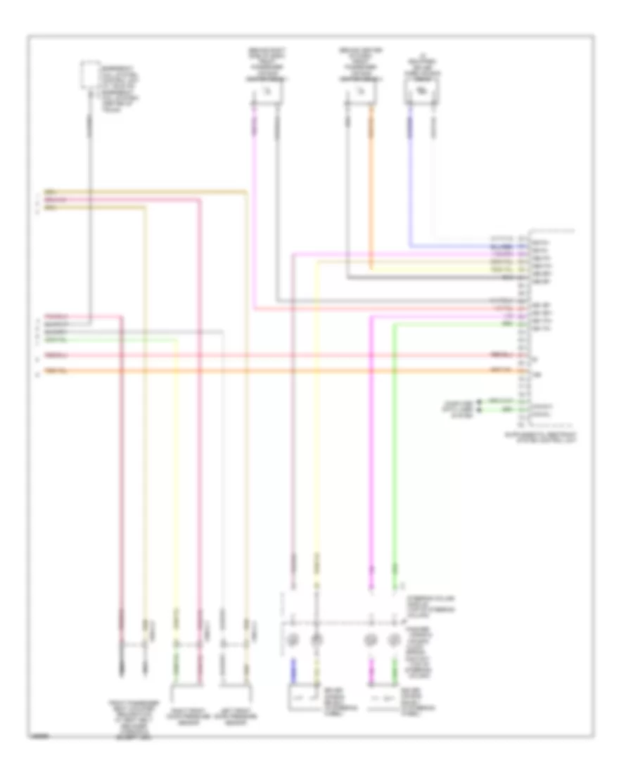
Automatic A/C Wiring Diagram, Sedan with Thermotronic (3 of 3) for Mercedes-Benz E350 2011
List of elements for Automatic A/C Wiring Diagram, Sedan with Thermotronic (3 of 3) for Mercedes-Benz E350 2011:
- (-)
- (behind center console, inside heater box) (if equipped) ptc heater booster
- 3.0l turbo
- Ac housing
- Air re- circulation mode button
- Automatic air conditioning control & operating unit
- Blower motor
- Blower regulator
- Can-h
- Can-l
- Combustion engine & a/c w/ integrated control fan motor
- Computer data lines system
- Coolant temperature sensor (except 3.0l turbo: rear of left cylinder bank) (3.0l turbo: top left side of engine)
- Diffuse flap actuator motor
- Engine controls system
- Except 3.0l turbo
- Fresh air/ recirculated air flaps actuator motor (under right side of dash)
- Front prefuse (right front footwell)
- Fuse 100a
- Fuse 150a
- Fuse 50a
- Fuse 7.5a
- Hot at all times
- Hot w/ quiescent current cutout relay energized
- Left blending air flap actuator (behind center of dash)
- Left center air flap actuator motor (under center of dash)
- Left defroster vent flap actuator motor (behind center of dash)
- Left footwell flap actuator motor (behind left front of center console)
- Lin b8
- Lues
- Me-sfi (me) control module (except 3.0l turbo) (center rear of engine compt) cdi control module (3.0l turbo) (left rear of engine compt)
- Mr4
- Mr5
- Nwg m2
- Ptc heater booster electrical connector
- Purge control valve
- Ram air flap actuator motor
- Rear blend air flap actuator motor (front of center console)
- Rear sam sam control module w/ fuse/ relay module (left side of trunk)
- Red
- Reg f
- Right blending air flap actuator (behind center of dash)
- Right center air flap actuator motor (under center of dash)
- Right defroster vent flap actuator motor (behind center of dash)
- Right footwell flap actuator motor (behind right front of center console)
- Sig
- Tmot m
- W15/5
- W2 (w/ 800 w fan motor) (behind right headlight unit) w9 (w/ 650 w fan motor) (behind left headlight unit)
- X18-c4
- X25/2-c1
Automatic A/C Wiring Diagram, Sedan without Thermotronic (1 of 3) for Mercedes-Benz E350 2011
List of elements for Automatic A/C Wiring Diagram, Sedan without Thermotronic (1 of 3) for Mercedes-Benz E350 2011:
- 12v
- 30g
- Air re cir- culation mode button
- Automatic air conditioning control & operating unit
- C-aac sun sensor (center rear of engine compt hood)
- C13d
- C14m
- C20m
- C21m
- C5c
- Can-b h
- Can-b l
- Computer data lines system
- Diesel
- Driver side sam control module w/ fuse/ relay module (left rear of engine compt)
- Evaporator temperature sensor (right side of dash)
- Fresh air/ recirculated air flap switchover valve
- Fuse 7.5a
- Gas
- Gnd
- Hot at all times
- Interior temperature sensor (left side of dash)
- Interior temperature sensor w/ integrated fan
- Lin b8
- Ntc (+)
- Ntc (-)
- Outside temperature sensor
- Overhead control panel control module (w/ tilting/ sliding roof) (in overhead console)
- Overhead control panel electronics (w/o tilting/ sliding roof)
- Rear window heater button
- Red
- Refrigerant compressor (left front engine)
- Refrigerant pressure sensor (left front of engine compt)
- Right front footwell air outlet temperature sensor (right front footwell area)
- Right side air outlet temperature sensor
- Sig
- Sig li
- Sig re
- Solid state
- W15/5
- X26-c1
Automatic A/C Wiring Diagram, Sedan without Thermotronic (2 of 3) for Mercedes-Benz E350 2011
List of elements for Automatic A/C Wiring Diagram, Sedan without Thermotronic (2 of 3) for Mercedes-Benz E350 2011:
- (or red)
- 58d
- Ac housing
- Blower motor
- Blower regulator
- C14m
- C17c
- C18m
- C19i
- C22i
- C3m
- C4i
- Can-b h
- Can-b l
- Computer data lines system
- Driver side sam control module w/ fuse/ relay module (left rear of engine compt)
- Fuse 15a
- Hot w/ engine circuit 87 relay energized
- Left center air outlet symbol illumination
- Left front footwell air outlet temperature sensor (left front footwell area)
- Left front side air outlet symbol illumination
- Left side air outlet temperature sensor
- Rear air outlet symbol illumination
- Red
- Right center air outlet symbol illumination
- Right front side air outlet symbol illumination
- Usa
- Vehicle interior humidity/ temperature sensor (w/ eco start/ stop function)
- W/ air outlet symbol illumination
- W15/5
- W18 (w/o direct select) w19 (w/ direct select)
- X157/1-c2
- X18-c4
- X25/2-c1
- X83/11-c2
Automatic A/C Wiring Diagram, Sedan without Thermotronic (3 of 3) for Mercedes-Benz E350 2011
List of elements for Automatic A/C Wiring Diagram, Sedan without Thermotronic (3 of 3) for Mercedes-Benz E350 2011:
- (-)
- (behind center console, inside heater box) (if equipped) ptc heater booster
- 3.0l turbo
- Air distribution vent flap actuator motor
- Can e h
- Can e l
- Combustion engine & a/c w/ integrated control fan motor
- Computer data lines system
- Coolant temperature sensor (except 3.0l turbo: rear of left cylinder bank) (3.0l turbo: top left side of engine)
- Defroster vent flap actuator motor
- Engine controls system
- Except 3.0l turbo
- Fresh air/ recirculated air flaps actuator motor (under right side of dash)
- Front prefuse (right front footwell)
- Fuse 100a
- Fuse 150a
- Fuse 50a
- Hot at all times
- Left blending air flap actuator
- Lues
- Me-sfi (me) control module (except 3.0l turbo) (center rear of engine compt) cdi control module (3.0l turbo) (left rear of engine compt)
- Mr4
- Mr5
- Nwg m2
- Ptc heater booster electrical connector
- Purge control valve (except 3.0l turbo)
- Red
- Reg
- Right blending air flap actuator
- Tmot
- W15/7
- W2 (w/ 800 w fan motor) (behind right headlight unit) w9 (w/ 650 w fan motor) (behind left headlight unit)
- X25/2-c1
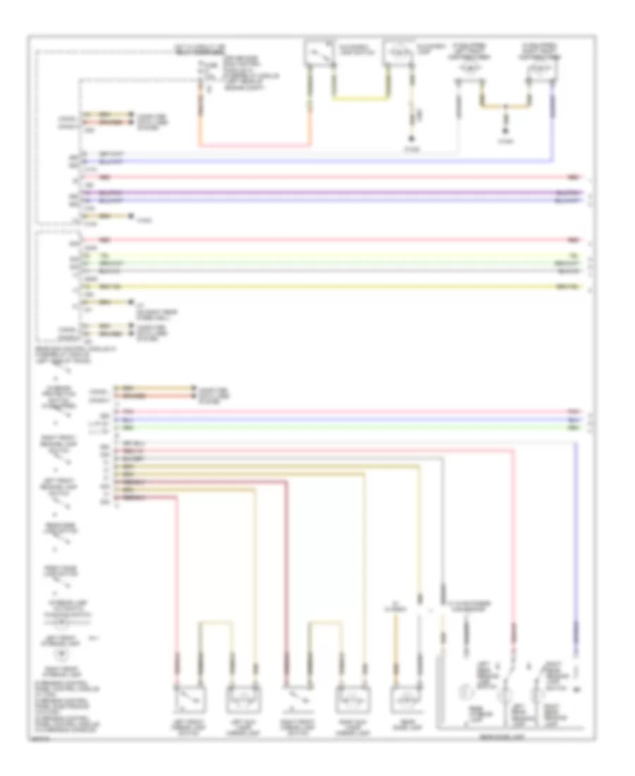
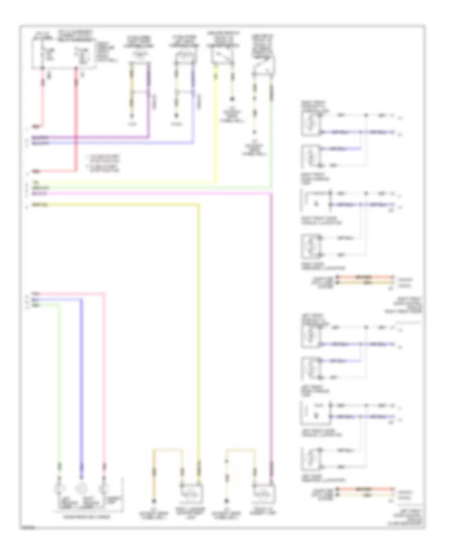
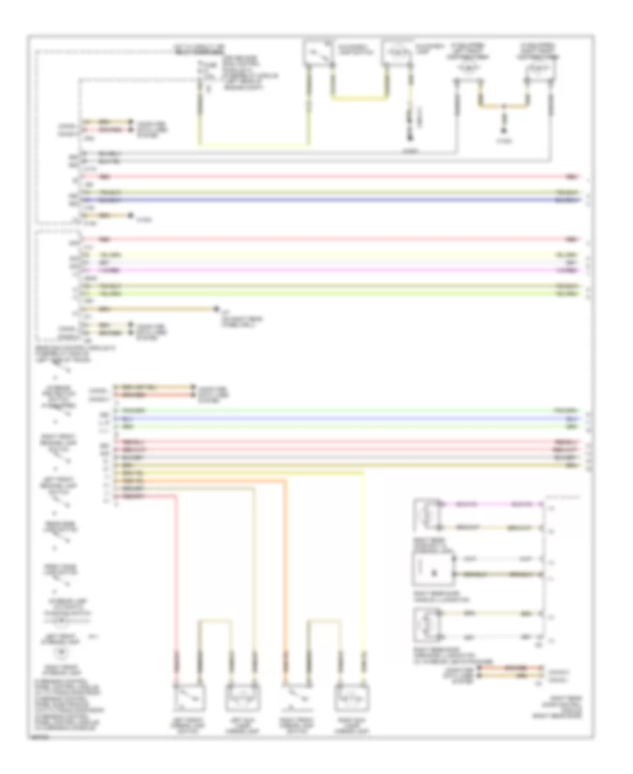
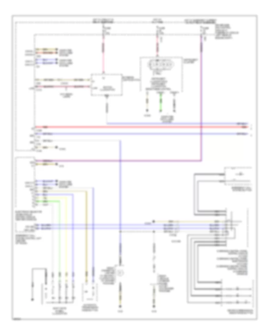
ANTI-LOCK BRAKES
Anti-lock Brakes Wiring Diagram, Coupe with Basic (1 of 2) for Mercedes-Benz E350 2011
List of elements for Anti-lock Brakes Wiring Diagram, Coupe with Basic (1 of 2) for Mercedes-Benz E350 2011:
- (-)
- + 12v
- 30g
- Bla
- Bls_h
- Bls_l
- Bls_m
- Brake vacuum sensor (w/ eco start/stop)
- Can d h
- Can d l
- Can e h
- Can e l
- Computer data lines system
- Df hl m
- Df hl s
- Df hr m
- Df hr s
- Df vl m
- Df vl s
- Df vr m
- Df vr s
- Eco
- Eco 12v
- Electronic stability program control unit
- Front axle brake pressure sensor
- Front axle intake ball valve
- Front axle switchover valve
- Front pressure sensor
- High pressure & return pump
- Left front pressure regulator valve (pressure hold)
- Left front pressure regulator valve (pressure release)
- Left front wheel speed sensor (left front wheel)
- Left rear pressure regulator valve (pressure hold)
- Left rear pressure regulator valve (pressure release)
- Left rear wheel speed sensor (left rear wheel)
- Nca
- Pml
- Pml 12v
- Power steering pump quantity control valve (if equipped)
- Rear axle intake ball valve
- Rear axle switchover valve
- Rear pressure sensor
- Rear sam control unit w/ fuse & relay module (left side c9i of trunk)
- Right front pressure regulator valve (pressure hold)
- Right front pressure regulator valve (pressure release)
- Right front wheel speed sensor (right front wheel)
- Right rear pressure regulator valve (pressure hold)
- Right rear pressure regulator valve (pressure release)
- Right rear wheel speed sensor (right rear wheel)
- Sig
- Stoplight switch (left front upper footwell)
- Traction system hydraulic unit (left front engine compt)
- W70
- X26-c1
- X35/6
- X62/32-c4
- X62/33-c4
- X62/6
- X62/7
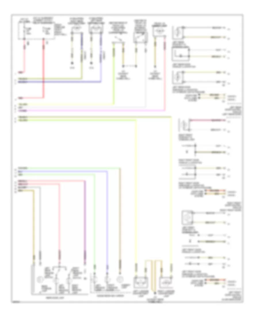
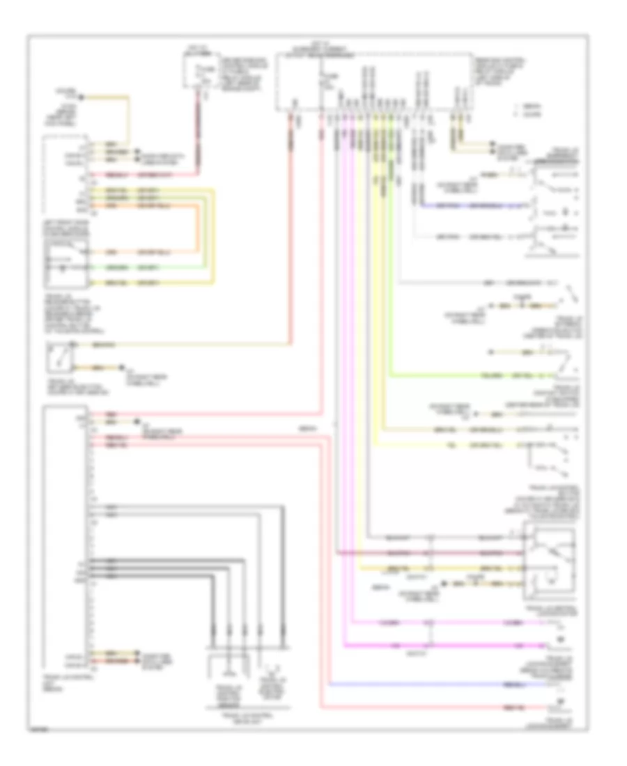
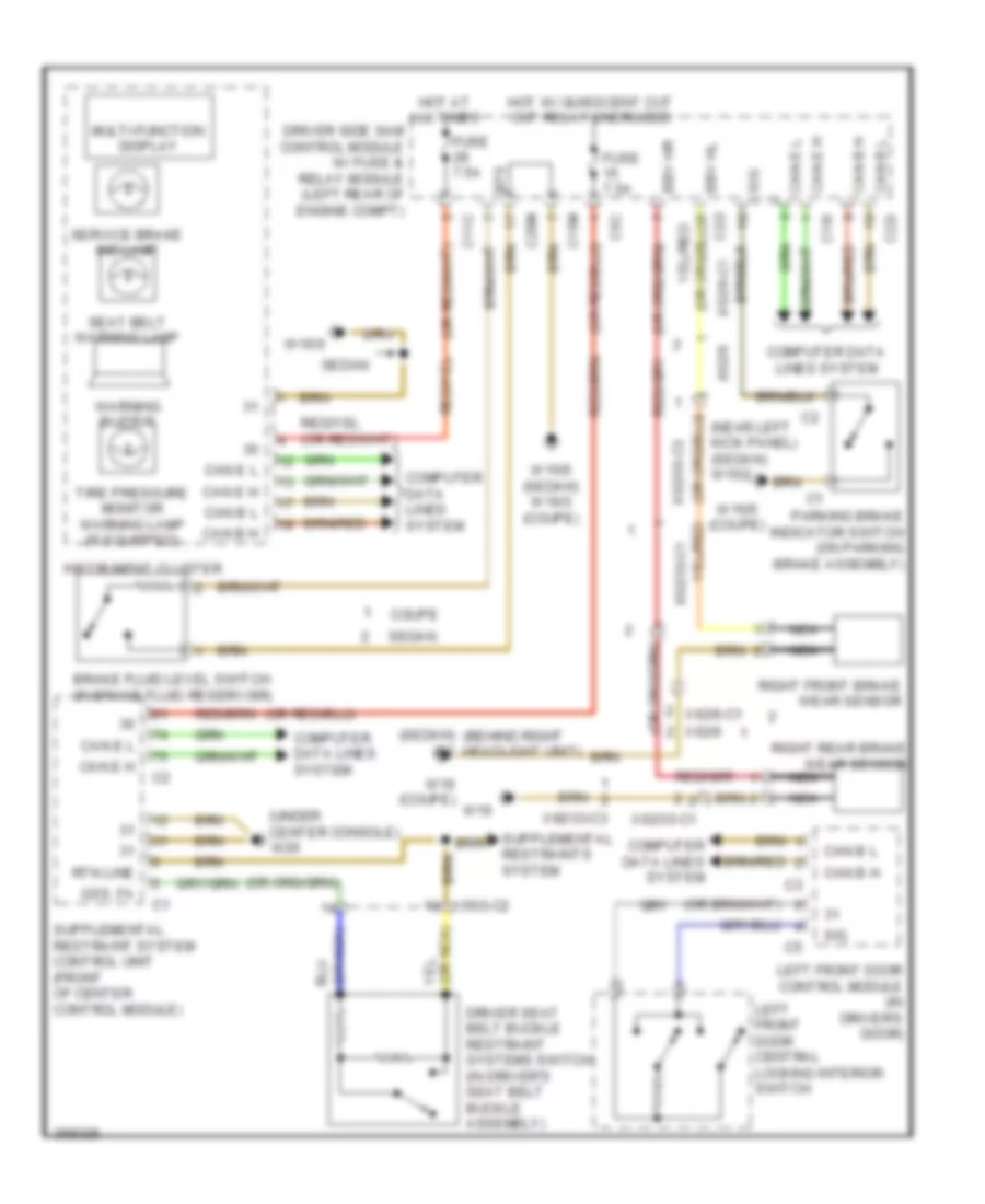
Anti-lock Brakes Wiring Diagram, Coupe with Basic (2 of 2) for Mercedes-Benz E350 2011
List of elements for Anti-lock Brakes Wiring Diagram, Coupe with Basic (2 of 2) for Mercedes-Benz E350 2011:
- Antilock brake system indicator lamp
- Brake fluid & parking brake warning lamp
- Brake fluid level switch (in brake fluid reservoir)
- C11c
- C15m
- C19i
- C20m
- C22i
- C2i
- C7i
- Can b h
- Can b l
- Computer data lines system
- Driver side sam control module with fuse/ relay module (left rear of engine compt)
- Electronic stability program warning lamp
- Fuse 25a
- Fuse 50a
- Fuse 7.5a
- Hot at all times
- Hot w/ circuit 15r relay energized
- Instrument cluster
- Parking brake indicator switch (on parking brake assembly)
- Service brake indicator lamp
- Speed-sensitive power steering solenoid valve (if equipped)
- W15/5
- W16/5
- X18-c1
- X18/33
- Yaw rate, lateral & longitudinal acceleration sensor
Anti-lock Brakes Wiring Diagram, Coupe with Premium (1 of 2) for Mercedes-Benz E350 2011
List of elements for Anti-lock Brakes Wiring Diagram, Coupe with Premium (1 of 2) for Mercedes-Benz E350 2011:
- (-)
- + 12v
- 30g
- Bla
- Bls_h
- Bls_l
- Bls_m
- Brake vaccume sensor (w/ eco start/stop)
- Can e h
- Can e l
- Can h h
- Can h l
- Computer data lines system
- Df hl m
- Df hl s
- Df hr m
- Df hr s
- Df vl m
- Df vl s
- Df vr m
- Df vr s
- Eco
- Eco 12v
- Front axle brake pressure sensor
- Front axle intake ball valve
- Front axle switchover valve
- Front pressure sensor
- High pressure & return pump
- Left front pressure regulator valve (pressure hold)
- Left front pressure regulator valve (pressure release)
- Left front wheel speed sensor (left front wheel)
- Left rear pressure regulator valve (pressure hold)
- Left rear pressure regulator valve (pressure release)
- Left rear wheel speed sensor (left rear wheel)
- Nca
- Pml
- Pml 12v
- Power steering pump quantity control valve
- Premium electronic stability program control unit
- Rear axle intake ball valve
- Rear axle switchover valve
- Rear pressure sensor
- Rear sam control unit w/ fuse & relay module (left side c9i of trunk)
- Right front pressure regulator valve (pressure hold)
- Right front pressure regulator valve (pressure release)
- Right front wheel speed sensor (right front wheel)
- Right rear pressure regulator valve (pressure hold)
- Right rear pressure regulator valve (pressure release)
- Right rear wheel speed sensor (right rear wheel)
- Sig
- Stoplight switch (left front upper footwell)
- Traction system hydraulic unit (left front of engine compt)
- W70
- X26-c1
- X35/6
- X62/32-c4
- X62/33-c4
- X62/6
- X62/7
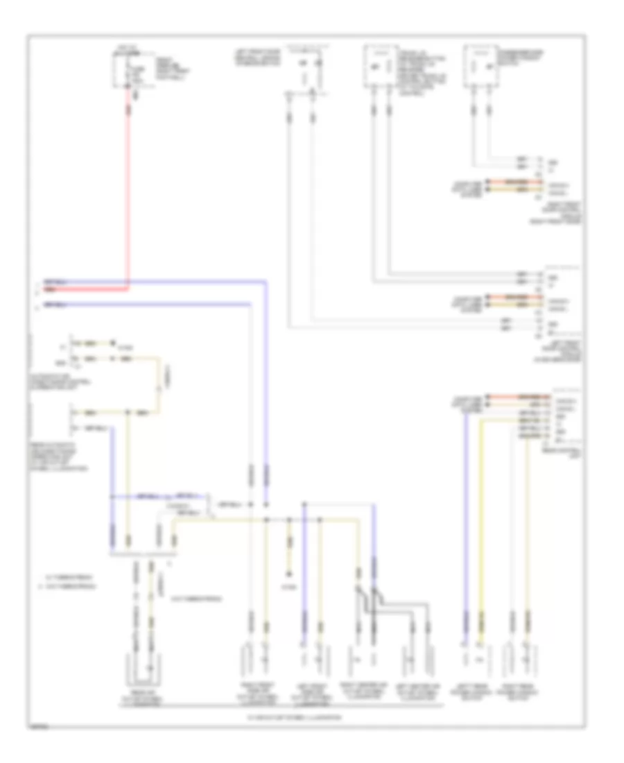
Anti-lock Brakes Wiring Diagram, Coupe with Premium (2 of 2) for Mercedes-Benz E350 2011
List of elements for Anti-lock Brakes Wiring Diagram, Coupe with Premium (2 of 2) for Mercedes-Benz E350 2011:
- Antilock brake system indicator lamp
- Brake fluid & parking brake warning lamp
- Brake fluid level switch (in brake fluid reservoir)
- C11c
- C15m
- C19i
- C20m
- C22i
- C2i
- C7i
- Can b h
- Can b l
- Computer data lines system
- Driver side sam control module with fuse/ relay module (left rear of engine compt)
- Electronic stability program warning lamp
- Fuse 25a
- Fuse 50a
- Fuse 7.5a
- Hot at all times
- Hot w/ circuit 15r relay energized
- Instrument cluster
- Parking brake indicator switch (on parking brake assembly)
- Service brake indicator lamp
- Speed-sensitive power steering solenoid valve (if equipped)
- W15/5
- W16/3
- X18-c1
- X18/33
- Yaw rate, lateral & longitudinal acceleration sensor
Anti-lock Brakes Wiring Diagram, Sedan with Basic (1 of 2) for Mercedes-Benz E350 2011
List of elements for Anti-lock Brakes Wiring Diagram, Sedan with Basic (1 of 2) for Mercedes-Benz E350 2011:
- (-)
- + 12v
- 30g
- Bla
- Bls_h
- Bls_l
- Bls_m
- Brake vacuum sensor (w/ eco start/stop)
- Can e h
- Can e l
- Can h h
- Can h l
- Computer data lines system
- Df hl m
- Df hl s
- Df hr m
- Df hr s
- Df vl m
- Df vl s
- Df vr m
- Df vr s
- Eco
- Eco 12v
- Electronic stability program control unit
- Front axle brake pressure sensor
- Front axle intake ball valve
- Front axle switchover valve
- High pressure & return pump
- K-line
- Left front pressure regulator valve (pressure hold)
- Left front pressure regulator valve (pressure release)
- Left front wheel speed sensor (left front wheel)
- Left rear pressure regulator valve (pressure hold)
- Left rear pressure regulator valve (pressure release)
- Left rear wheel speed sensor (left rear wheel)
- Nca
- Pml
- Pml 12v
- Power steering pump quantity control valve
- Rear axle intake ball valve
- Rear axle switchover valve
- Rear sam control unit w/ fuse & relay module (left side c9i of trunk)
- Right front pressure regulator valve (pressure hold)
- Right front pressure regulator valve (pressure release)
- Right front wheel speed sensor (right front wheel)
- Right rear pressure regulator valve (pressure hold)
- Right rear pressure regulator valve (pressure release)
- Right rear wheel speed sensor (right rear wheel)
- Sig
- Ssk_stat
- Stoplight switch (left front upper footwell)
- Traction system hydraulic unit (left front engine compt)
- W70
- X26-c1
- X62/32-c4
- X62/33-c4
- X62/6-c1
- X62/7-c1
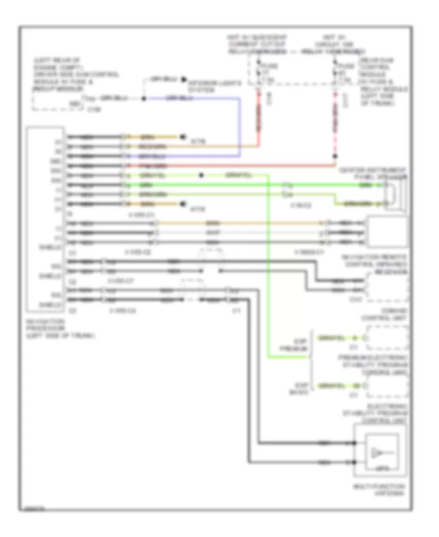
Anti-lock Brakes Wiring Diagram, Sedan with Basic (2 of 2) for Mercedes-Benz E350 2011
List of elements for Anti-lock Brakes Wiring Diagram, Sedan with Basic (2 of 2) for Mercedes-Benz E350 2011:
- Antilock brake system indicator lamp
- Brake fluid & parking brake warning lamp
- Brake fluid level switch (in brake fluid reservoir)
- C11c
- C15m
- C19i
- C20m
- C22i
- C2i
- C7i
- Can b h
- Can b l
- Computer data lines system
- Driver side sam control module with fuse/ relay module (left rear of engine compt)
- Electronic stability program warning lamp
- Fuse 25a
- Fuse 40a
- Fuse 7.5a
- Hot at all times
- Hot w/ circuit 15 relay energized
- Instrument cluster
- Mirror taximeter (if equipped)
- Navigation processor (w/ external navigation) (left side of trunk)
- Nca
- Parking brake indicator switch (on parking brake assembly)
- Right front brake wear sensor
- Right rear brake wear sensor
- Service brake indicator lamp
- Speed-sensitive power steering solenoid valve (if equipped)
- W15/2 (near left kick panel)
- W15/5
- W19
- W2 (behind right headlight unit)
- X1/55-c1
- X18/33-c1
- X62/33-c1
- X62/6-c1
- Yaw rate, lateral & longitudinal acceleration sensor
Anti-lock Brakes Wiring Diagram, Sedan with Premium (1 of 2) for Mercedes-Benz E350 2011
List of elements for Anti-lock Brakes Wiring Diagram, Sedan with Premium (1 of 2) for Mercedes-Benz E350 2011:
- (-)
- + 12v
- 30g
- Bla
- Bls_h
- Bls_l
- Bls_m
- Brake vacuum sensor (w/ eco start/stop)
- Can e h
- Can e l
- Can h h
- Can h l
- Computer data lines system
- Df hl m
- Df hl s
- Df hr m
- Df hr s
- Df vl m
- Df vl s
- Df vr m
- Df vr s
- Eco
- Eco 12v
- Front axle brake pressure sensor
- Front axle intake ball valve
- Front axle switchover valve
- Front pressure sensor
- High pressure & return pump
- K-line
- Left front pressure regulator valve (pressure hold)
- Left front pressure regulator valve (pressure release)
- Left front wheel speed sensor (left front wheel)
- Left rear pressure regulator valve (pressure hold)
- Left rear pressure regulator valve (pressure release)
- Left rear wheel speed sensor (left rear wheel)
- Nca
- Pml
- Pml 12v
- Power steering pump quantity control valve
- Premium electronic stability program control unit
- Rear axle intake ball valve
- Rear axle switchover valve
- Rear pressure sensor
- Rear sam control unit w/ fuse & relay module (left side c9i of trunk)
- Right front pressure regulator valve (pressure hold)
- Right front pressure regulator valve (pressure release)
- Right front wheel speed sensor (right front wheel)
- Right rear pressure regulator valve (pressure hold)
- Right rear pressure regulator valve (pressure release)
- Right rear wheel speed sensor (right rear wheel)
- Sig
- Ssk_stat
- Stoplight switch (left front upper footwell)
- Traction system hydraulic unit (left front engine compt)
- W70
- X26-c1
- X62/32-c4
- X62/33-c4
- X62/6-c1
- X62/7-c1
Anti-lock Brakes Wiring Diagram, Sedan with Premium (2 of 2) for Mercedes-Benz E350 2011
List of elements for Anti-lock Brakes Wiring Diagram, Sedan with Premium (2 of 2) for Mercedes-Benz E350 2011:
- Antilock brake system indicator lamp
- Brake fluid & parking brake warning lamp
- Brake fluid level switch (in brake fluid reservoir)
- C11c
- C15m
- C19i
- C20m
- C22i
- C2i
- C7i
- Can b h
- Can b l
- Computer data lines system
- Driver side sam control module with fuse/ relay module (left rear of engine compt)
- Electronic stability program warning lamp
- Fuse 25a
- Fuse 40a
- Fuse 7.5a
- Hot at all times
- Hot w/ circuit 15r relay energized
- Instrument cluster
- Mirror taximeter (if equipped)
- Navigation processor (w/ external navigation) (left side of trunk)
- Nca
- Parking brake indicator switch (on parking brake assembly)
- Right front brake wear sensor
- Right rear brake wear sensor
- Service brake indicator lamp
- Speed-sensitive power steering solenoid valve (if equipped)
- W15/2 (near left kick panel)
- W15/5
- W19
- W2 (behind right headlight unit)
- X1/55-c1
- X18/33-c1
- X62/33-c1
- X62/6-c1
- Yaw rate, lateral & longitudinal acceleration sensor
ANTI-THEFT
Anti-theft Alarm Wiring Diagram for Mercedes-Benz E350 2011
List of elements for Anti-theft Alarm Wiring Diagram for Mercedes-Benz E350 2011:
- (left rear of engine compt) driver side sam control module w/ fuse & relay module
- (on right rear wheelwell) w7
- (or pnk)
- (or red)
- 11c
- 12v
- 13d
- 15m
- 16s
- 20m
- 22i
- 56a
- 58d
- Alarm siren (w/ anti-theft alarm system)
- Anti-theft alarm system indicator lamp
- Ass led
- Ass off
- Ata (edw) hood switch (w/ anti-theft alarm system) (right front of engine compt)
- Can-b h
- Can-b l
- Can-e h
- Can-e l
- Computer data lines system
- Coupe
- Driver side power window & outside mirror adjustment switch group
- Emergency call system control unit (center of trunk)
- Ewd
- Exterior lights system
- Fan relay module
- Front prefuse (right front footwell)
- Fuse 100a
- Fuse 150a
- Fuse 17 30a
- Fuse 18 7.5a
- Fuse 46 7.5a
- Gnd
- Horns system
- Hot at all times
- Hot w/ quiescent current cutout relay energized
- Info
- Info led
- Instrument cluster
- Instrument panel switch group
- Interior protection & tow-away protection control unit
- Interior protection receiver
- Interior protection switch
- Irs led
- Irs-off
- Left front door control module (in driver's door)
- Left interior protection transmitter
- Lin 1
- Lin 35
- Lin b4
- Mg1
- Mr2
- Multi-function display
- Nca
- Off
- Overhead control panel control module (overhead control panel w/ can) (in overhead console) overhead control panel electronics (overhead control panel w/o can)
- Rear sam control module w/ fuse & relay module (left side of trunk)
- Rear side window child safety lock switch
- Red
- Right interior protection transmitter
- Sedan
- Sos
- Sos led
- Stop function
- Towing sensor button
- W/ eco start/ stop function
- W/o eco start/
- W15/5
- W15/7 (coupe)
- W16/3 (coupe) w15/2 (sedan) (sedan: near left kick panel)
- W2 (sedan) (behind right headlight unit)
- W6 (sedan: left rear wheelhousing)
- W7 (coupe) (on right rear wheelwell)
- W7/8 (sedan)
- Ws led
- X157/5-c2
- X18/2
- X18/37
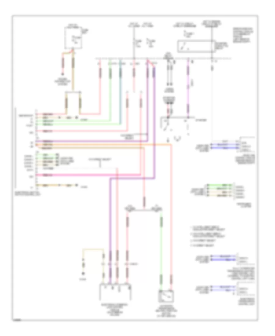
Drive Authorization System Wiring Diagram, Coupe for Mercedes-Benz E350 2011
List of elements for Drive Authorization System Wiring Diagram, Coupe for Mercedes-Benz E350 2011:
- 15m
- 30z
- Automatic transmission neutral position switch
- C11c
- C5c
- Can-b h
- Can-b l
- Can-c h
- Can-c l
- Can-e h
- Can-e l
- Computer data lines system
- Data
- Driver side sam control module w/ fuse & relay module (left rear of engine compt)
- Electronic ignition switch control unit
- Electronic steering lock control module (on steering column)
- Fan relay module
- Fully integrated transmission control (vgs) control unit (integral to electric control unit (vgs))
- Fuse 20a
- Fuse 7 20a
- Fuse 7.5a
- Horns system
- Hot at all times
- Hot w/ circuit 15 relay energized
- Hot w/ engine circuit 87 relay energized
- Instrument cluster
- Me-sfi (me) control module (center rear of engine compt)
- Red
- Starter
- Starter circuit 50 relay
- Starting/ charging system
- Str
- W/ keyless go
- W/o keyless go
- W15/5
- X26-c1
Drive Authorization System Wiring Diagram, Sedan for Mercedes-Benz E350 2011
List of elements for Drive Authorization System Wiring Diagram, Sedan for Mercedes-Benz E350 2011:
- 15m
- 30z
- Automatic transmission neutral position switch (w/ keyless go)
- C11c
- C17c
- C5c
- Can-b h
- Can-b l
- Can-c h
- Can-c l
- Can-e h
- Can-e l
- Computer data lines system
- Data
- Drievr side sam control module w/ fuse/relay module (left rear of engine compt)
- Electronic ignition switch control unit
- Electronic steering lock control module (on steering column)
- Electronic transmission control unit
- Ezs backup
- Fan relay module
- Fully integrated transmission control (vsg) control unit (integral to electric control unit (vgs))
- Fuse 20a
- Fuse 5a
- Fuse 7 20a
- Fuse 7.5a
- Fuse box
- Horns system
- Hot at all times
- Hot w/ circuit 15 relay energized
- Hot w/ engine circuit 87 relay energized
- Instrument cluster
- Me-sfi (me) control module (center rear of engine compt)
- Module for direct select
- P not
- Power distribution system
- Red
- Starter
- Starter circuit 50 relay
- Starting/ charging system
- Str
- W/ direct select
- W/ intelligent servo
- W/ keyless go
- W/o direct select
- W/o intelligent servo
- W/o keyless go
- W15/5
- X190-c1
- X26-c1
BODY CONTROL MODULES
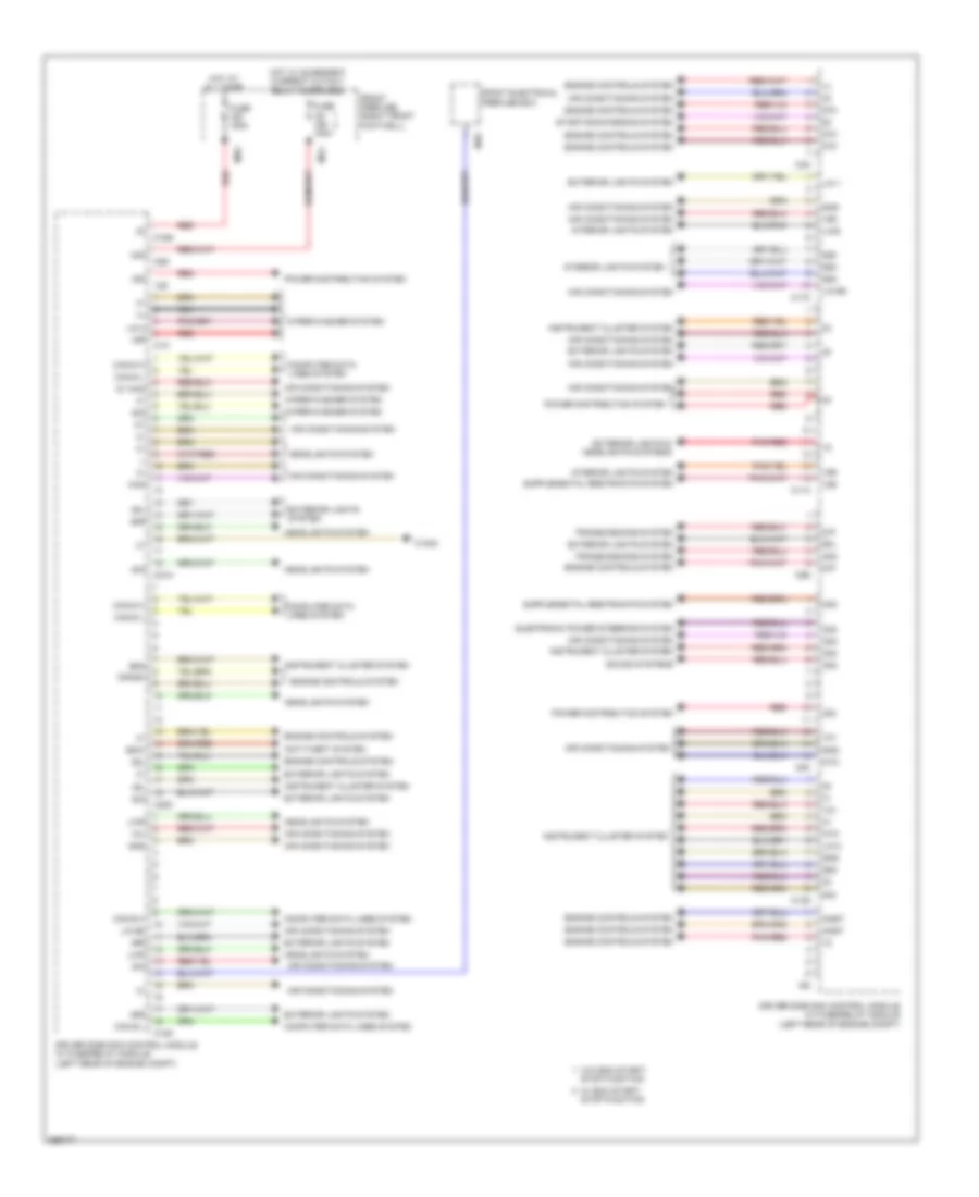
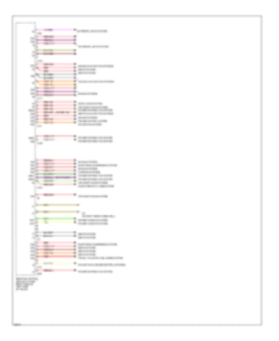
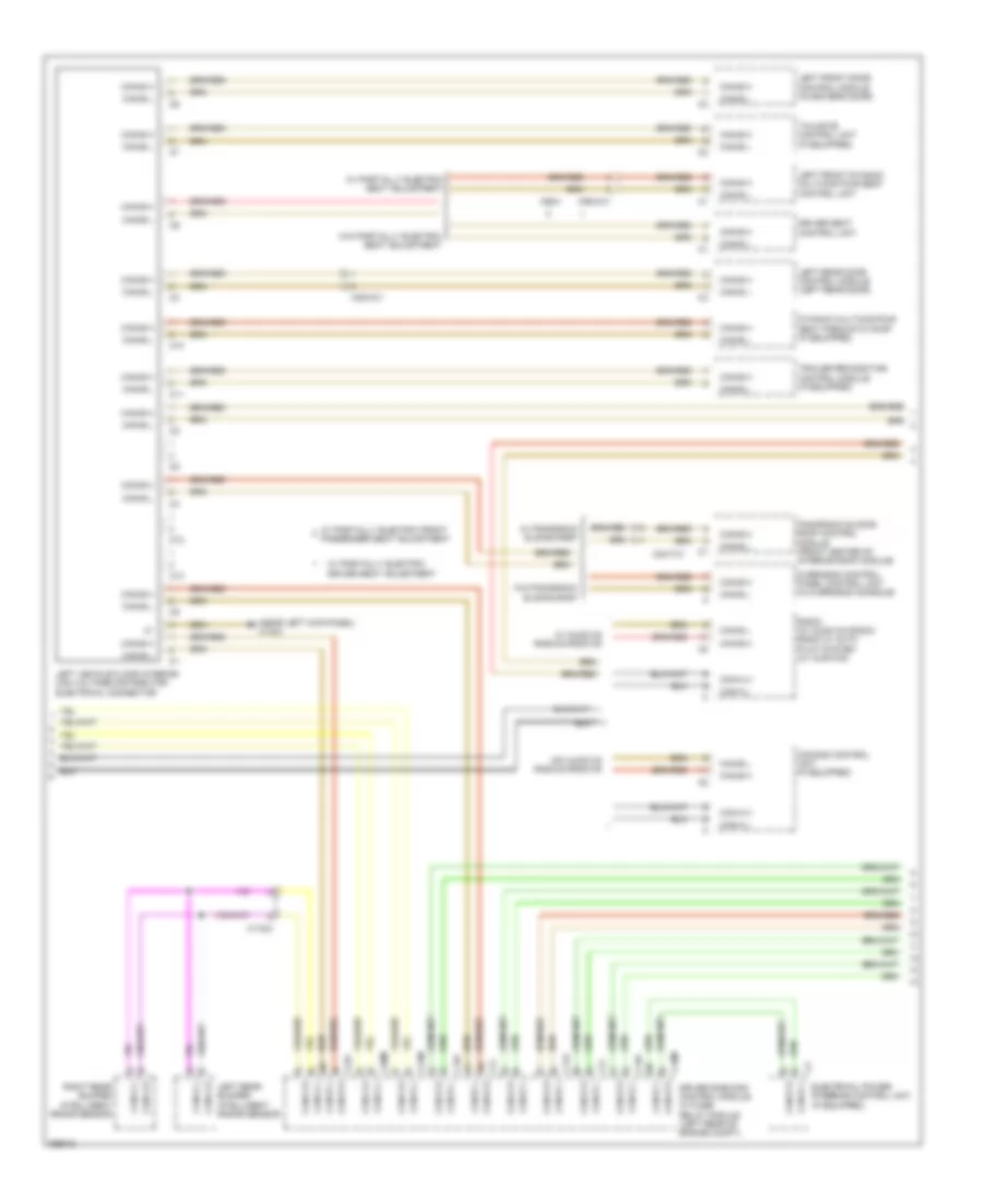
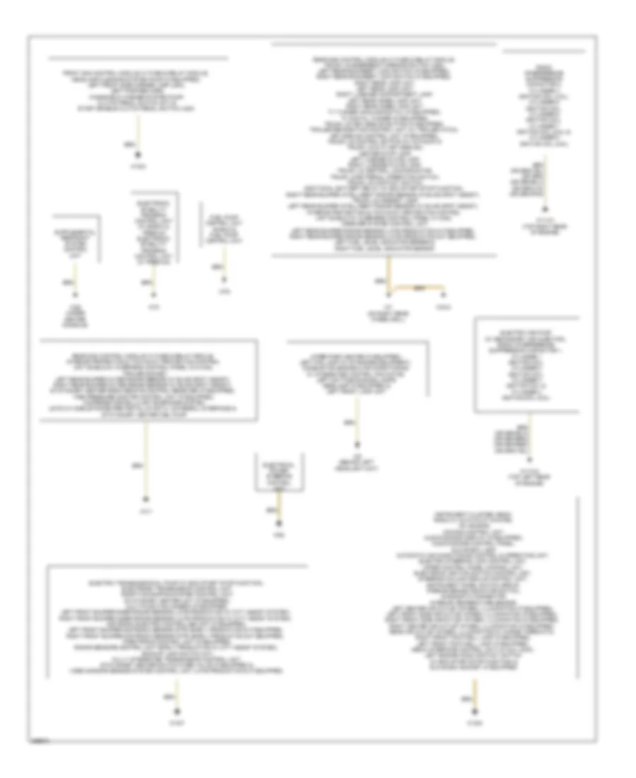
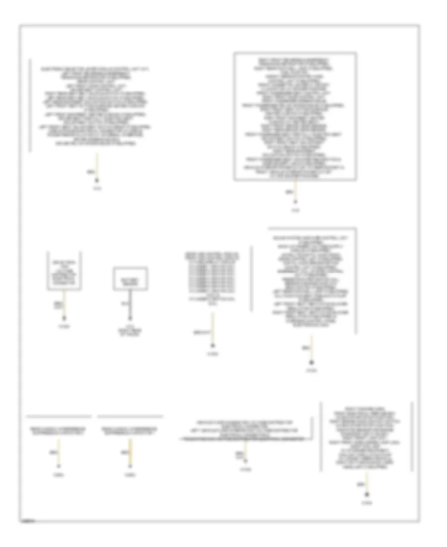
Driver"s Side SAM Control Module Wiring Diagram, Coupe (1 of 2) for Mercedes-Benz E350 2011
List of elements for Driver"s Side SAM Control Module Wiring Diagram, Coupe (1 of 2) for Mercedes-Benz E350 2011:
- (+)
- 12s
- 12v
- 15r
- 30g
- 30z
- 49l
- 49r
- 58d
- 58l
- 58r
- 5v khd
- 87f
- 87m
- Air conditioning system
- Anst
- Anti-theft system
- Bfs
- C11c
- C13d
- C16s
- C17c
- C18m
- C1m
- C20m
- C21m
- C3m
- C5c
- C6i
- C8s
- C9g
- Can e h
- Can e l
- Can-g h
- Can-g l
- Computer data lines system
- Crash
- Driver side sam control module w/ fuse/relay module (left rear of engine compt)
- Edw
- Electronic power steering system
- Engine controls system
- Exterior lights & headlights systems
- Exterior lights system
- Front electrical prefuse box
- Front prefuse (right front footwell)
- Fuse 100a
- Fuse 150a
- Gnd
- Headlights system
- Hot at all times
- Hot w/ quiescent current cutout relay energized
- Instrument cluster system
- Interior lights system
- Khd
- Lin 1
- Lin 2
- Lin b8
- Lwr
- M10
- Mg1
- Mr2
- Nca
- Ntc
- Pnk/red
- Power distribution system
- Red
- Rfl
- Sig
- Sound systems
- Starting/charging system
- Stop function
- Transmissions system
- W/ eco start/ stop function
- W/o eco start/
- W16/5
- Wiper/washer system
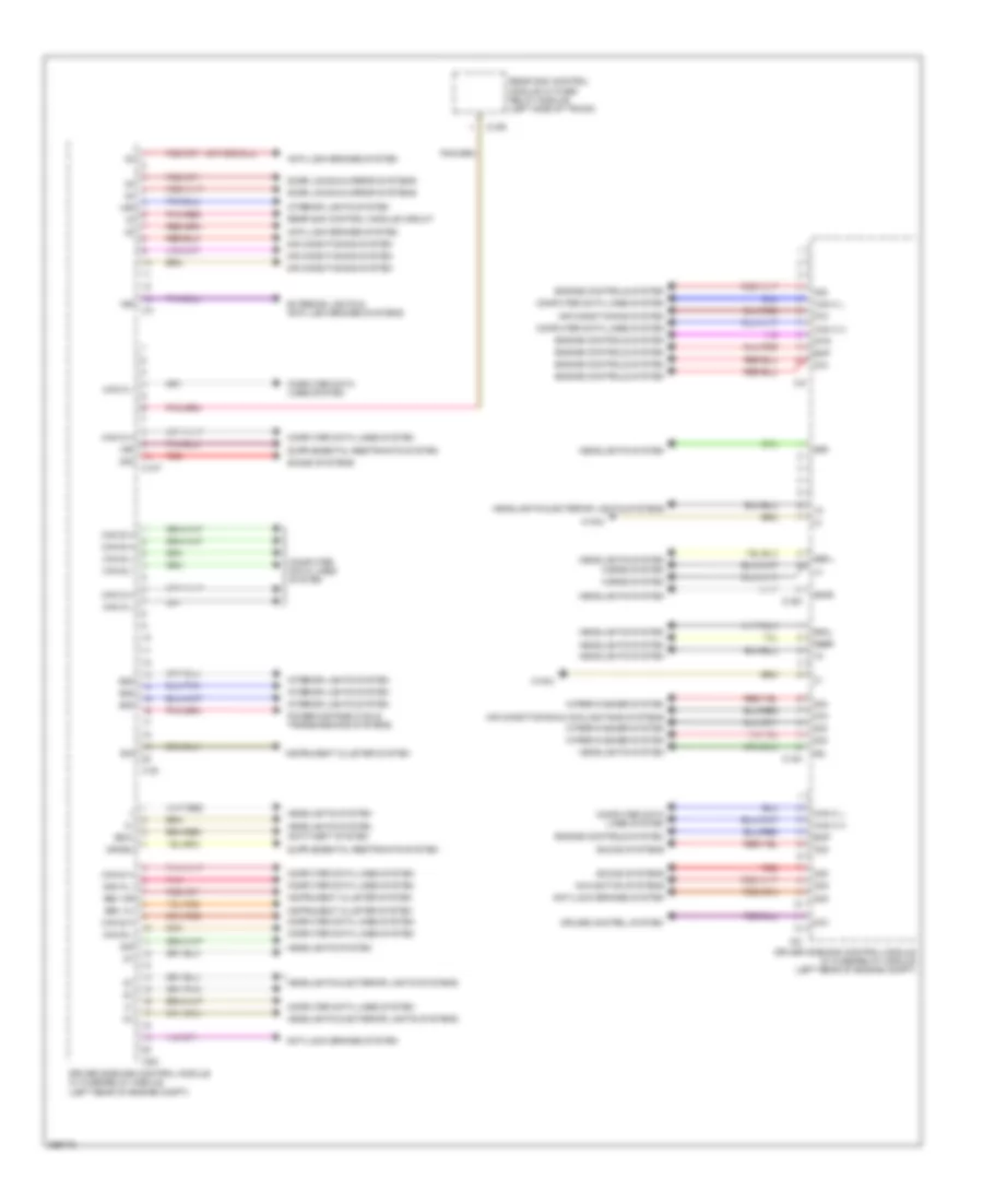
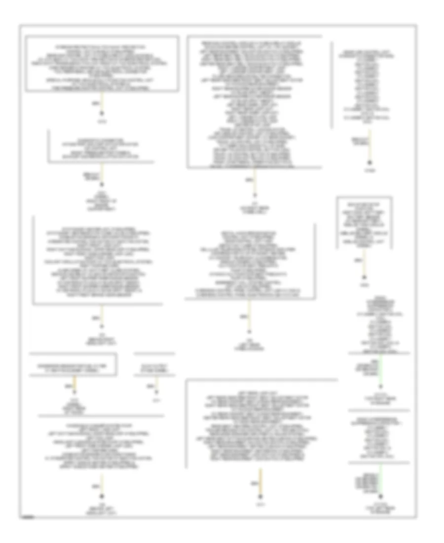
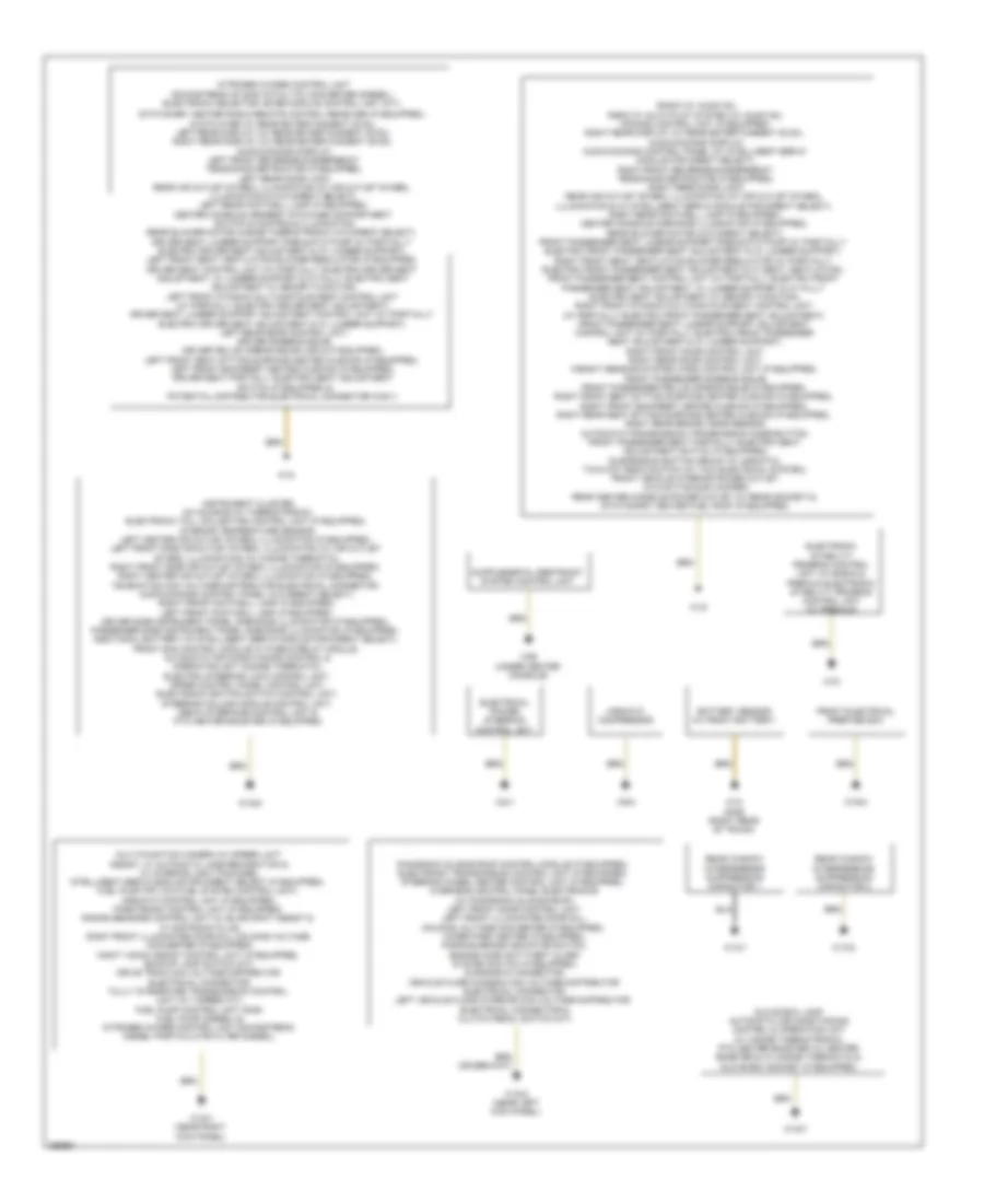
Driver"s Side SAM Control Module Wiring Diagram, Coupe (2 of 2) for Mercedes-Benz E350 2011
List of elements for Driver"s Side SAM Control Module Wiring Diagram, Coupe (2 of 2) for Mercedes-Benz E350 2011:
- (+)
- 15r
- 30g
- 30z
- 55l
- 55r
- 56al
- 56ar
- 56b l
- 56br
- 58d
- 87m
- Air conditioning & cooling fans systems
- Air conditioning system
- Anti-lock brakes system
- Anti-theft system
- Bbv hl
- Bbv hr
- C10r
- C10t
- C14m
- C15m
- C19i
- C22i
- C2i
- C4i
- C7i
- Can b h
- Can b l
- Can c h
- Can c l
- Can d h
- Can d l
- Can e h
- Can e l
- Can g h
- Can g l
- Computer data lines system
- Crash
- Cruise control system
- Door locks & mirror systems
- Driver side sam control module w/ fuse/relay module (left rear of engine compt)
- Edw
- Ekp
- Engine controls system
- Exterior lights & anti-lock brakes systems
- Headlights & exterior lights systems
- Headlights system
- Horns system
- Instrument cluster system
- Interior lights system
- Navigation systems
- Pnk
- Pnk/red
- Power distribution & transmissions systems
- Rear sam control module circuit
- Rear sam control module w/ fuse/ relay module (left side of trunk)
- Red
- Sig
- Sound systems
- Str
- W16/3
- Wiper/washer system
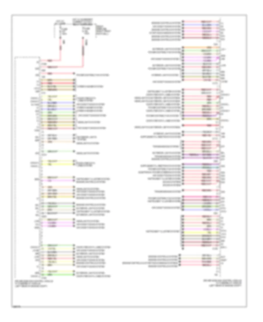
Driver"s Side SAM Control Module Wiring Diagram, Sedan (1 of 2) for Mercedes-Benz E350 2011
List of elements for Driver"s Side SAM Control Module Wiring Diagram, Sedan (1 of 2) for Mercedes-Benz E350 2011:
- (+)
- (or red)
- 12s
- 12v
- 15r
- 30g
- 30z
- 49l
- 49r
- 58d
- 58l
- 58r
- 5v khd
- 87f
- 87m
- Air conditioning system
- Anst
- Bfs
- C11c
- C13d
- C16s
- C17c
- C18m
- C1m
- C20m
- C21m
- C3m
- C5c
- C6i
- C8s
- C9g
- Can b h
- Can b l
- Can e h
- Can e l
- Can-g h
- Can-g l
- Computer data lines system
- Driver side sam control module w/ fuse/relay module (left rear of engine compt)
- Electronic power steering system
- Engine controls & starting/charging systems
- Engine controls system
- Exterior lights system
- Front prefuse (right front footwell)
- Fuse 100a
- Fuse 150a
- Gnd
- Headlights & exterior lights systems
- Headlights system
- Hot at all times
- Hot w/ quiescent current cutout relay energized
- Instrument cluster system
- Interior lights system
- Khd
- Lin 1
- Lin 2
- Lin b8
- Lwr
- Mr7
- Mrg2
- Ntc+
- Ntc-
- Pnk/red
- Power distribution system
- Red
- Rfl
- Sig
- Sig il
- Slp
- Sound systems
- Starting/charging system
- Transmissions system
- Wiper/washer system
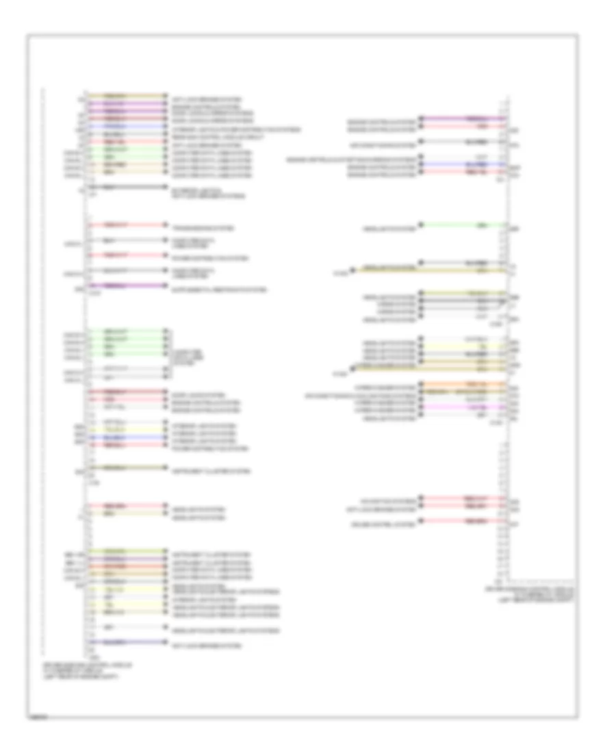
Driver"s Side SAM Control Module Wiring Diagram, Sedan (2 of 2) for Mercedes-Benz E350 2011
List of elements for Driver"s Side SAM Control Module Wiring Diagram, Sedan (2 of 2) for Mercedes-Benz E350 2011:
- (+)
- 15r
- 30g
- 30z
- 55l
- 55r
- 56a
- 56b
- 58d
- 87f
- 87m
- Air conditioning & cooling fans systems
- Air conditioning system
- Anti-lock brakes system
- Bbv hr
- Bbv vl
- C10t
- C14m
- C15m
- C19i
- C22i
- C2i
- C4i
- C7i
- Can b h
- Can b l
- Can d h
- Can d l
- Can e h
- Can e l
- Computer data lines system
- Cruise control system
- Door locks & mirror systems
- Door locks system
- Driver side sam control module w/ fuse/relay module (left rear of engine compt)
- Ekp
- Engine controls & starting/charging systems
- Engine controls system
- Exterior lights & anti-lock brakes systems
- Gnd
- Headlights & exterior lights systems
- Headlights system
- Headlights system headlights & exterior lights systems
- Horns system
- Instrument cluster system
- Interior lights & power distribution systems
- Interior lights system
- Navigation systems
- Power distribution system
- Rear sam control module circuit
- Red
- Sig
- Transmissions system
- W15/5
- Wiper/washer system
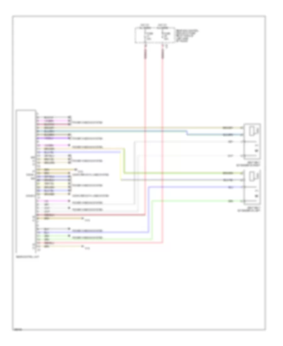
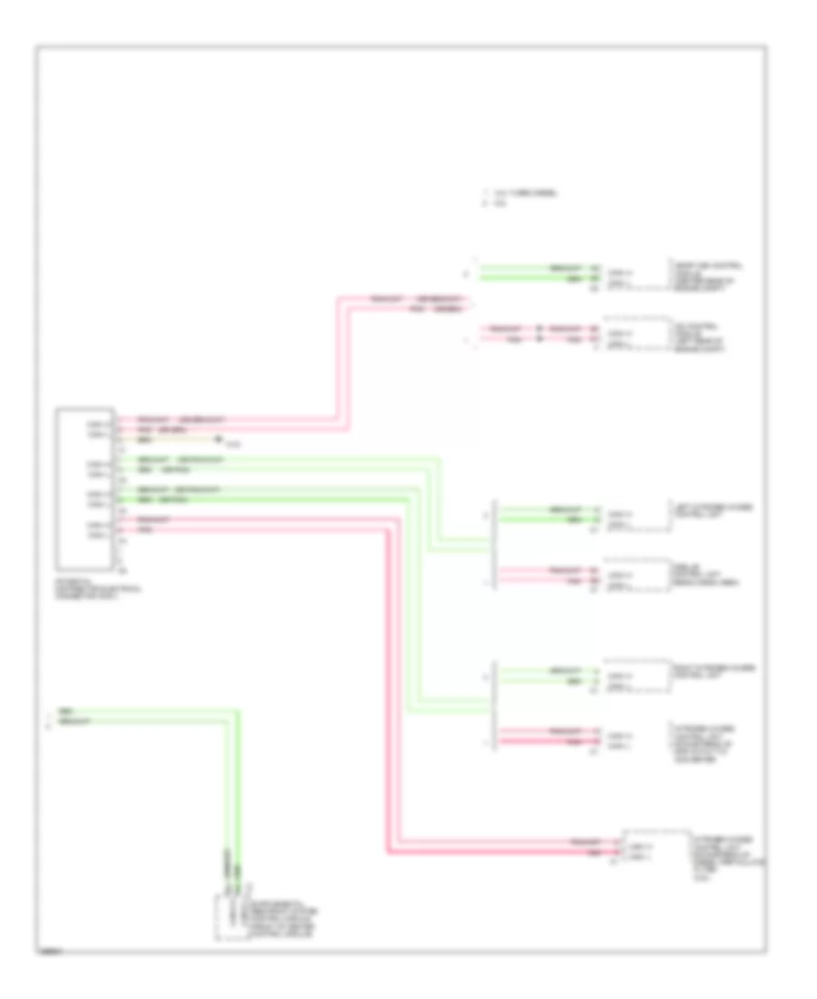
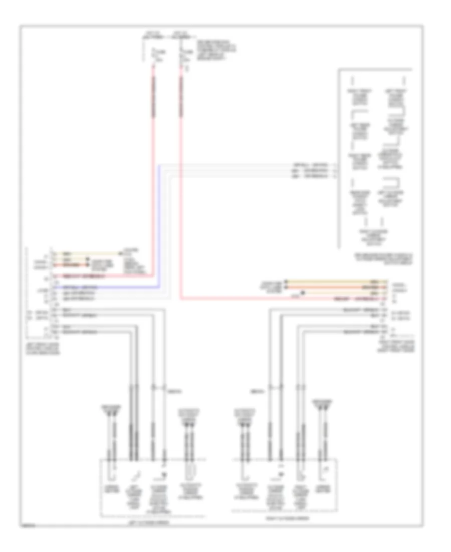
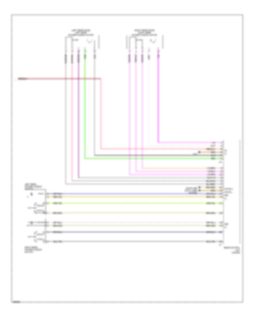
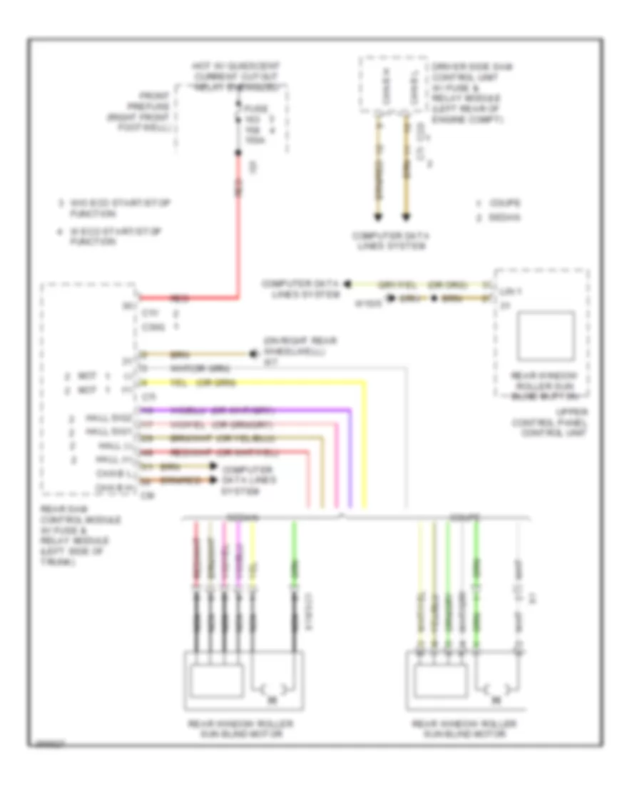
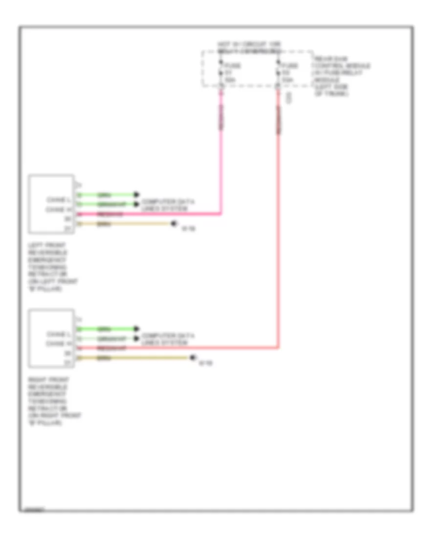
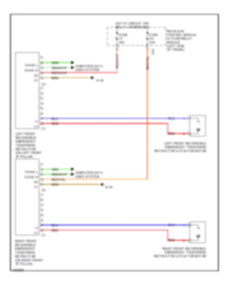
Rear Control Unit Wiring Diagram, Coupe for Mercedes-Benz E350 2011
List of elements for Rear Control Unit Wiring Diagram, Coupe for Mercedes-Benz E350 2011:
- 58d
- C3i
- Can-b h
- Can-b l
- Computer data lines system
- Fuse 30a
- Hot at all times
- Power windows system
- Rear control unit
- Rear sam control module w/ fuse/ relay module (left side of trunk)
- Seat belt extender on left
- Seat belt extender on right
- W18
Rear SAM Control Module Wiring Diagram, Coupe (1 of 2) for Mercedes-Benz E350 2011
List of elements for Rear SAM Control Module Wiring Diagram, Coupe (1 of 2) for Mercedes-Benz E350 2011:
- (+)
- 15r(1)
- 30g
- 31e
- 49l
- 49r
- 58d
- 58l
- Anti-lock brakes system
- Anti-theft system
- Bla
- Bsl-l
- Bsl-r
- C1h
- C2g
- C30
- C30g
- C3i
- C4hd
- C5h
- C6hd
- C7i
- C8d
- C9i
- Can b h
- Can b l
- Computer data lines system
- Defogger system
- Door locks system
- Driver side sam control module w/ fuse/relay module (left rear of engine compt)
- Edw
- Exterior lights system
- Front prefuse (right front footwell)
- Fuse 150a
- Gss hl
- Gss hr
- Headlights system
- Hfe
- Hot w/ quiescent current cutout relay energized
- Ig1
- Instrument cluster
- Instrument cluster & anti-theft systems
- Instrument cluster & engine controls systems
- Instrument cluster system
- Interior lights system
- Lin
- Lin b4
- Navigation system
- Nsl-l
- Nsl-r
- Pnk
- Pnk/red
- Power distribution system
- Power windows system
- Rear control unit circuit
- Rear sam control module w/ fuse/ relay module (left side of trunk)
- Red
- Rfl-l
- Rfl-r
- Rss aus
- Rss ein
- Seats system
- Sig
- Sl-l
- Sl-r
- Sound systems
- Starting/charging system
- Stop function
- System
- Tg l
- Tg r
- Trunk, tailgate, fuel doors system
- W/ eco start/ stop function
- W/o eco start/
- W7 (on right rear wheelwell)
- Zv ant
Rear SAM Control Module Wiring Diagram, Coupe (2 of 2) for Mercedes-Benz E350 2011
List of elements for Rear SAM Control Module Wiring Diagram, Coupe (2 of 2) for Mercedes-Benz E350 2011:
- (+)
- (-)
- (or pnk/red)
- 15r(1)
- 15r(2)
- 30g
- Air conditioning system
- C10r
- C11t
- C12i
- C13a
- C14i
- C15h
- C7i
- C89
- Compensator/cellular telephone system umts (w/ mobile phone preinstallation w/ universal interface & w/ stationary heater)
- Computer data lines system
- Cruise control & navigation systems
- Cruise control system
- Door locks system
- Driver side sam control module circuit
- Electronic suspension system
- Exterior lights system
- Navigation & cruise control systems
- Navigation & sound systems
- Navigation system
- Power distribution system
- Power windows system
- Rear sam control module w/ fuse/ relay module (left side of trunk)
- Red
- Seats system
- Sound systems
- W7 (on right rear wheelwell)
- W7/1
- Warning systems
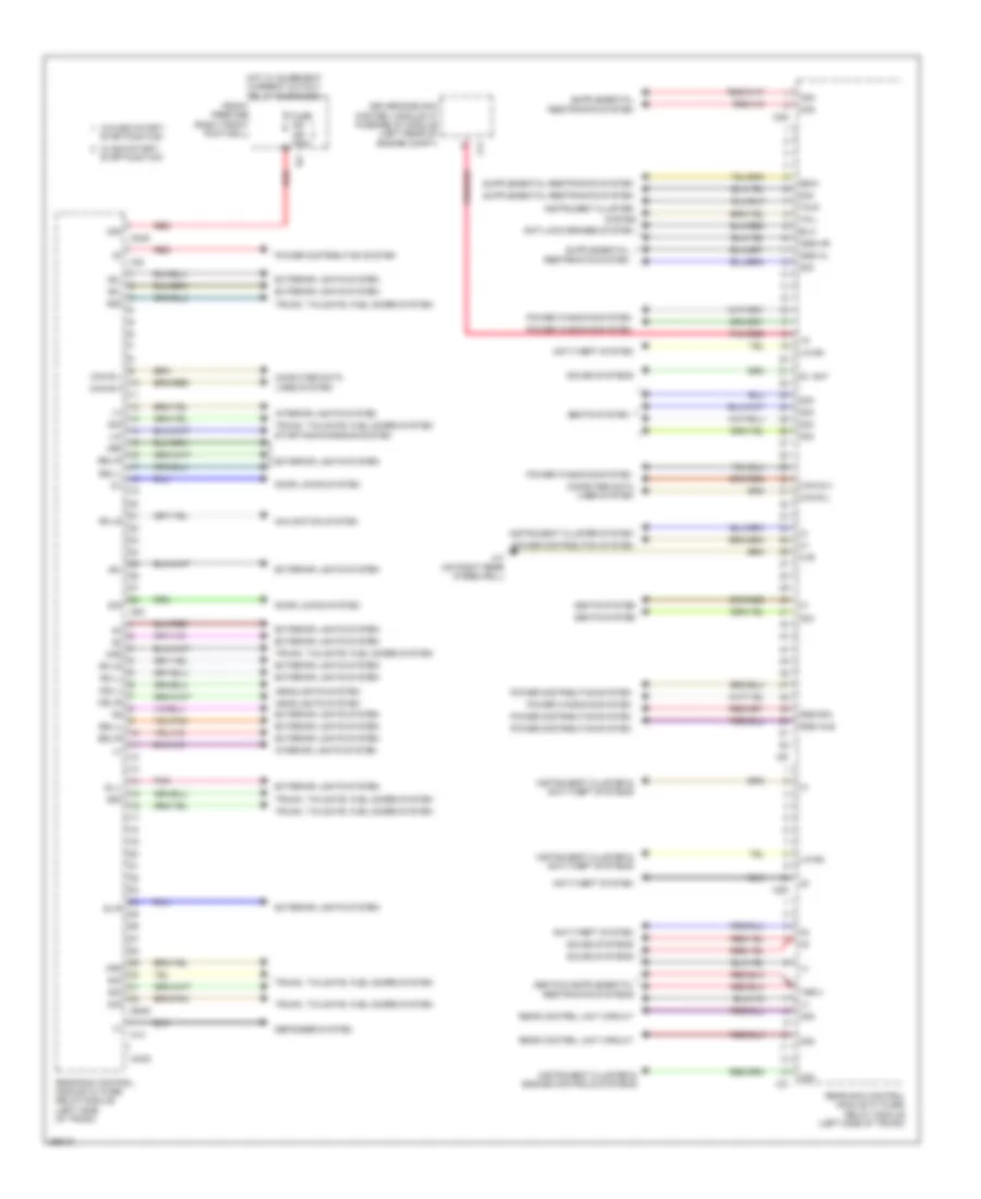
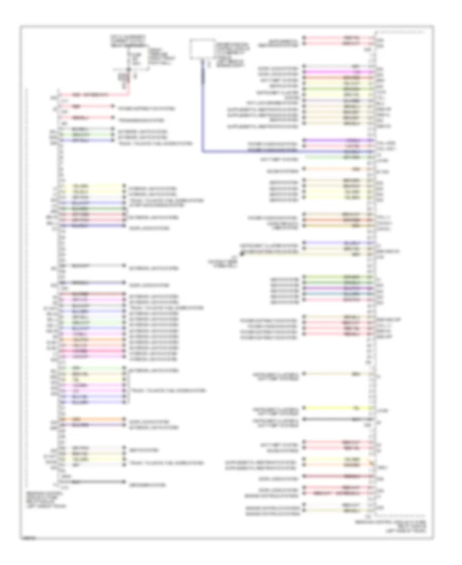
Rear SAM Control Module Wiring Diagram, Sedan (1 of 2) for Mercedes-Benz E350 2011
List of elements for Rear SAM Control Module Wiring Diagram, Sedan (1 of 2) for Mercedes-Benz E350 2011:
- (+)
- 15r(1)
- 30g
- 31e
- 49l
- 49r
- 58d
- 58l
- 58r
- Anti-lock brakes system
- Anti-theft system
- Bla
- Bsl-l
- Bsl-r
- C1h
- C1v
- C2g
- C2v
- C3i
- C5h
- C6hd
- C7i
- C8d
- C9i
- Can b h
- Can b l
- Computer data lines system
- Defogger system
- Door locks system
- Driver side sam control module w/ fuse/relay module (left rear of engine compt)
- Edm
- Engine controls systems
- Exterior lights system
- Front prefuse (right front footwell)
- Fuse 150a
- Gss hl
- Gss hm
- Gss hr
- Hall (+)
- Hall (-)
- Hall sig 1
- Hall sig2
- Hot w/ quiescent current cutout relay energized
- Ig1
- Instrument cluster
- Instrument cluster & anti-theft systems
- Instrument cluster system
- Interior lights system
- Ism
- Lin
- Lin b4
- Nsl-l
- Nsl-r
- Power distribution system
- Power windows system
- Rear sam control module w/ fuse/ relay module (left side of trunk)
- Red
- Rfl-l
- Rfl-r
- Rss gnd off
- Rss gnd on
- Rss off
- Rss on
- Seats system
- Sig
- Sig 90
- Sl/bl
- Sml
- Smr
- Sound systems
- Starting/charging system
- System
- Tg l
- Tg r
- Transmissions system
- Trunk, tailgate, fuel doors system
- W7 (on right rear wheelwell)
- Zv mot
- Zv sig
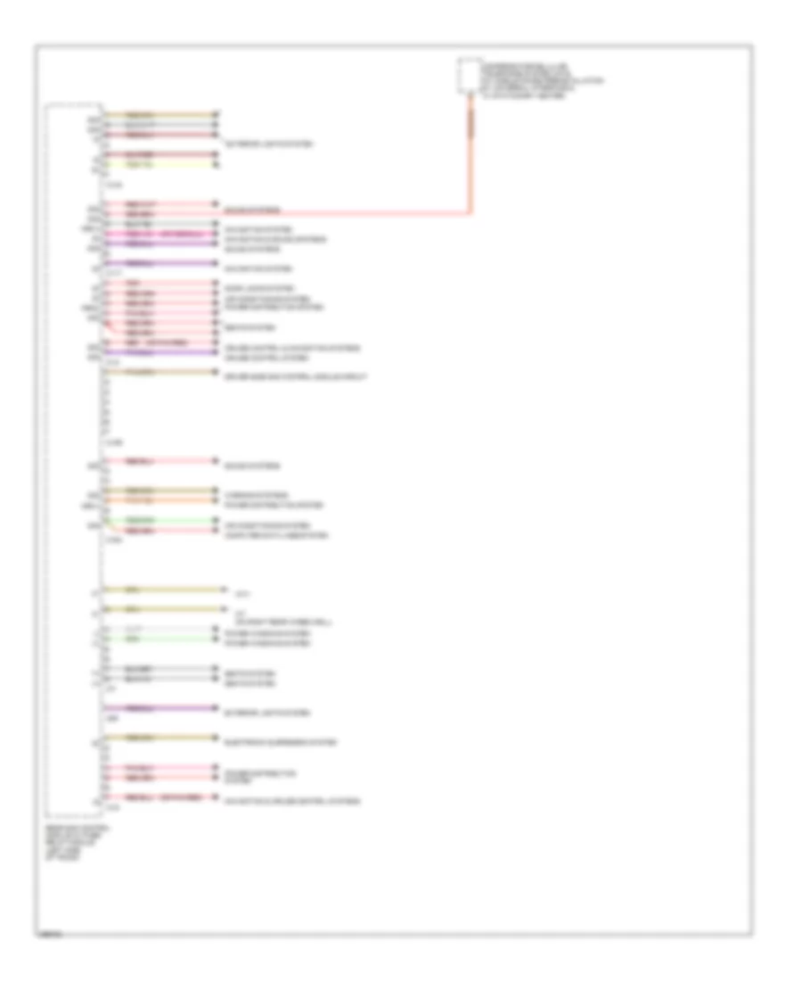
Rear SAM Control Module Wiring Diagram, Sedan (2 of 2) for Mercedes-Benz E350 2011
List of elements for Rear SAM Control Module Wiring Diagram, Sedan (2 of 2) for Mercedes-Benz E350 2011:
- (+)
- 15r
- 15r(1)
- 15r(2)
- 30g
- Aag
- Air conditioning system
- C10r
- C11t
- C12i
- C13a
- C14i
- C15h
- C7i
- Computer data lines system
- Cruise control system
- Door locks system
- Electronic suspension system
- Exterior lights system
- Mot
- Navigation & cruise control systems
- Navigation system
- Power distribution system
- Power windows system
- Rear sam control module w/ fuse/ relay module (left side of trunk)
- Red
- Scr
- Seats & navigation systems
- Seats system
- Sound & navigation systems
- Sound systems
- Trunk, tailgate, fuel doors system
- W7 (on right rear wheelwell)
- Warning systems
COMPUTER DATA LINES
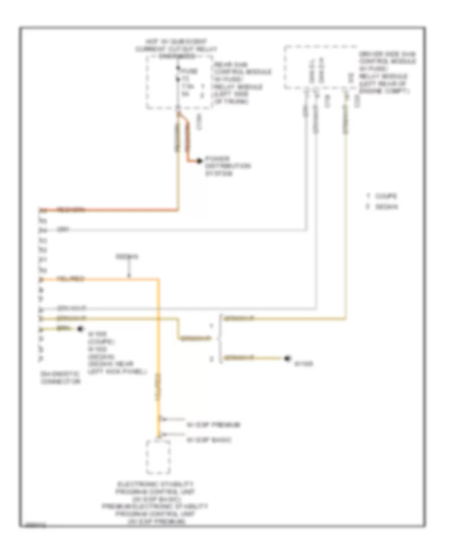
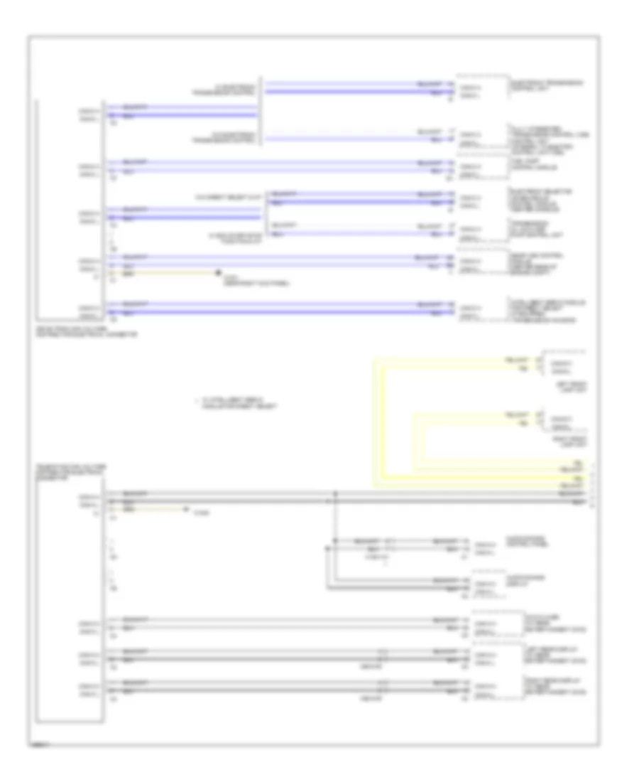
Data Link Connector Wiring Diagram for Mercedes-Benz E350 2011
List of elements for Data Link Connector Wiring Diagram for Mercedes-Benz E350 2011:
- 31e
- C15h
- C19i
- C22i
- Can d h
- Can d l
- Coupe
- Diagnostic connector
- Driver side sam control module w/ fuse/ relay module (left rear of engine compt)
- Electronic stability program control unit (w/ esp basic) premium electronic stability program control unit (w/ esp premium)
- Fuse 7.5a 5a
- Hot w/ quiescent current cutout relay energized
- Power distribution system
- Rear sam control module w/ fuse/ relay module (left side of trunk)
- Sedan
- W/ esp basic
- W/ esp premium
- W15/5 (coupe) w15/2 (sedan) (sedan: near left kick panel)
- W16/5
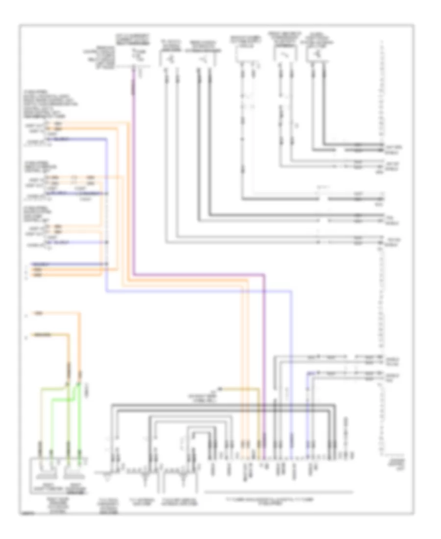
High/Low Bus Wiring Diagram, Coupe (1 of 4) for Mercedes-Benz E350 2011
List of elements for High/Low Bus Wiring Diagram, Coupe (1 of 4) for Mercedes-Benz E350 2011:
- Audio/comand control panel
- Audio/comand display
- Can-a h
- Can-a l
- Can-c h
- Can-c l
- Can-g h
- Can-g l
- Drive train can voltage distributor electrical connector
- Electronic selector lever module control module (a/t) (center console)
- Fuel pump control module
- Fully integrated transmission control (vgs) control unit (integral to electric control unit (vgs))
- Left front lamp unit
- Left xenon lamp control unit
- Right front lamp unit
- Right xenon light control unit
- Telematics can voltage distributor electrical connector
- Transmission oil auxiliary pump control unit (w/ eco start/stop function & a/t)
- W/ audio 20 & audio 50
- W/ comand
- W15/6
- W15/8 (m/t)
High/Low Bus Wiring Diagram, Coupe (2 of 4) for Mercedes-Benz E350 2011
List of elements for High/Low Bus Wiring Diagram, Coupe (2 of 4) for Mercedes-Benz E350 2011:
- Automatic air conditioning control & operating unit (2 & 3 zones thermatic)
- C10
- C10i
- C11
- C12
- C13
- C18m
- C19i
- C20m
- C21m
- C22i
- C2i
- C4i
- C5h
- Can-a h
- Can-a l
- Can-b h
- Can-b l
- Can-c h
- Can-c l
- Can-d h
- Can-d l
- Can-e h
- Can-e l
- Can-g h
- Can-g l
- Comand control unit
- Driver seat control unit
- Driver side sam control module w/ fuse/ relay module (left rear of engine compt)
- Emergency call system control unit (w/ teleaid emergency call system) (center of trunk)
- Left front door control module (in driver's door)
- Left rear bumper intelligent radar sensor
- Left vehicle floor interior can voltage distributor electrical connector
- Panoramic sliding roof control module (front center of interior roof module)
- Pnk
- Radio (w/ audio 20 radio) radio w/ auto pilot system (w/ audio 50)
- Rear door control module (rear door)
- Rear sam control module w/ fuse/relay module (left side of trunk)
- Right front door control module (right front door)
- Right rear bumper intelligent radar sensor
- Trailer recognition control unit
- W/ audio 20 & audio 50
- W/o audio 20 & audio 50
- W15/6
- X35/28
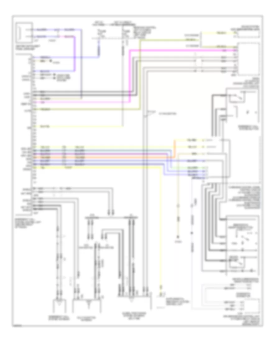
High/Low Bus Wiring Diagram, Coupe (3 of 4) for Mercedes-Benz E350 2011
List of elements for High/Low Bus Wiring Diagram, Coupe (3 of 4) for Mercedes-Benz E350 2011:
- Backup camera control unit (w/ backup camera)
- C10
- C11
- C12
- C13
- Can-b h
- Can-b l
- Can-e h
- Can-e l
- Can-h h
- Can-h l
- Front passenger seat control unit
- Instrument cluster
- Keyless go control unit (if equipped)
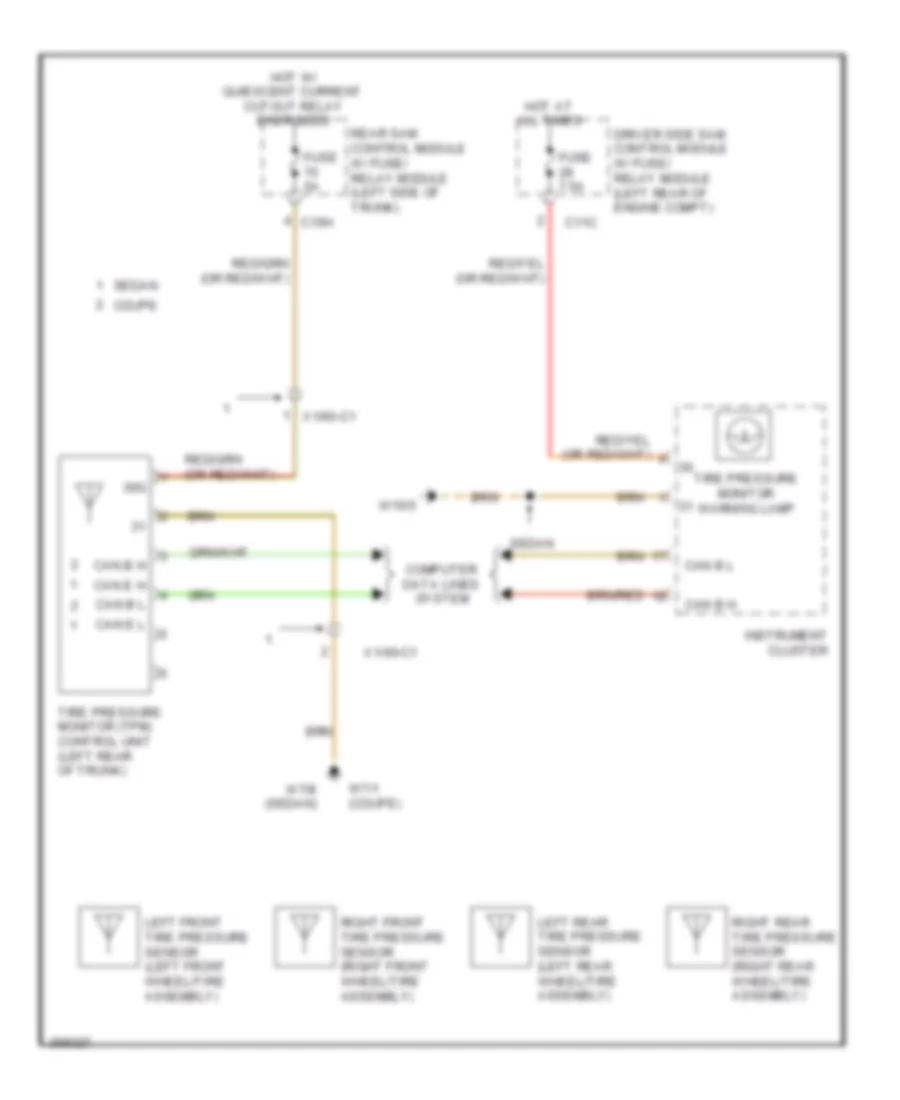
- Left front reversible emergency tensioning retractor (if equipped) (on left front "b" pillar)
- Parktronic control unit
- Right vehicle floor interior can voltage distributor electrical connector
- Stationary heater unit (if equipped) (right front engine compt)
- Steering column module (top of steering column)
- Tire pressure monitor control unit (if equipped)
- Vehicle floor chassis can voltage distributor electrical connector
- Video & radar sensor system control unit
- W/ parktronic
- W/o parktronic
- W15/6
- Weight sensing system control unit (if equipped) (under right front seat)
- X55/4-c2
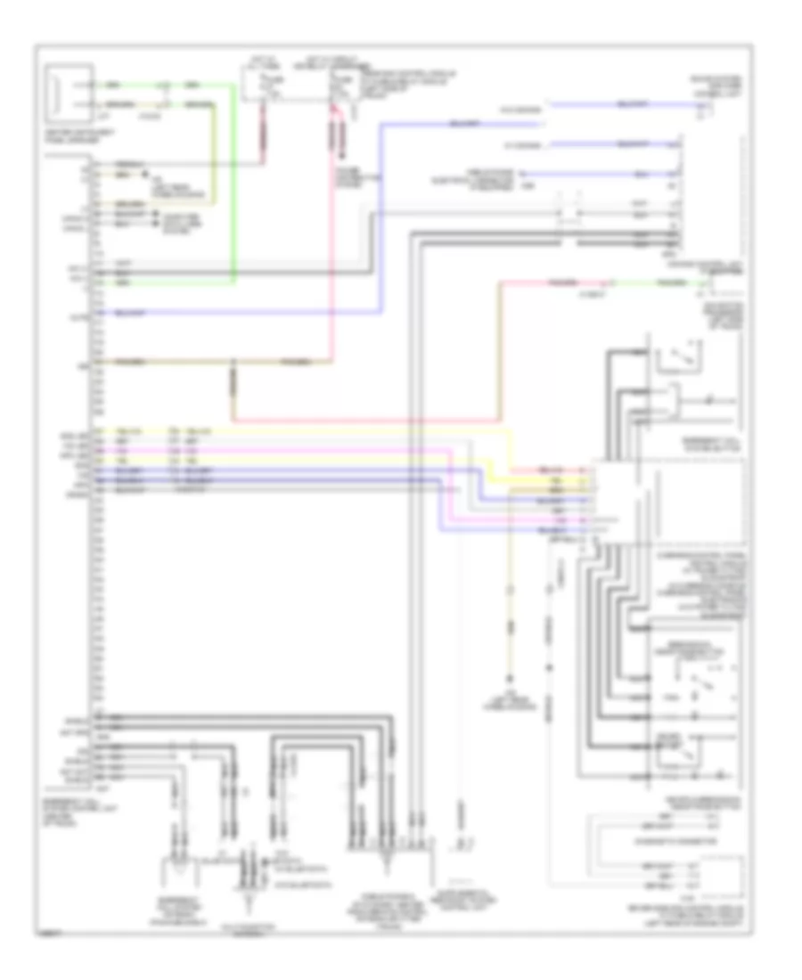
High/Low Bus Wiring Diagram, Coupe (4 of 4) for Mercedes-Benz E350 2011
List of elements for High/Low Bus Wiring Diagram, Coupe (4 of 4) for Mercedes-Benz E350 2011:
- Adaptive damping system control unit (if equipped)
- Can-b h
- Can-b l
- Can-c h
- Can-c l
- Can-e h
- Can-e l
- Can-h h
- Can-h l
- Distronic electric controller unit (if equipped) (front center engine compt)
- Electrical power steering control unit (if equipped)
- Electronic ignition switch control unit
- Electronic stability program control unit (w/ esp basic) premium electronic stability program control unit (w/ esp premium)
- Me-sfi (me) control module (except 3.0l turbo) (center rear of engine compt) cdi control module (3.0l turbo) (left rear of engine compt)
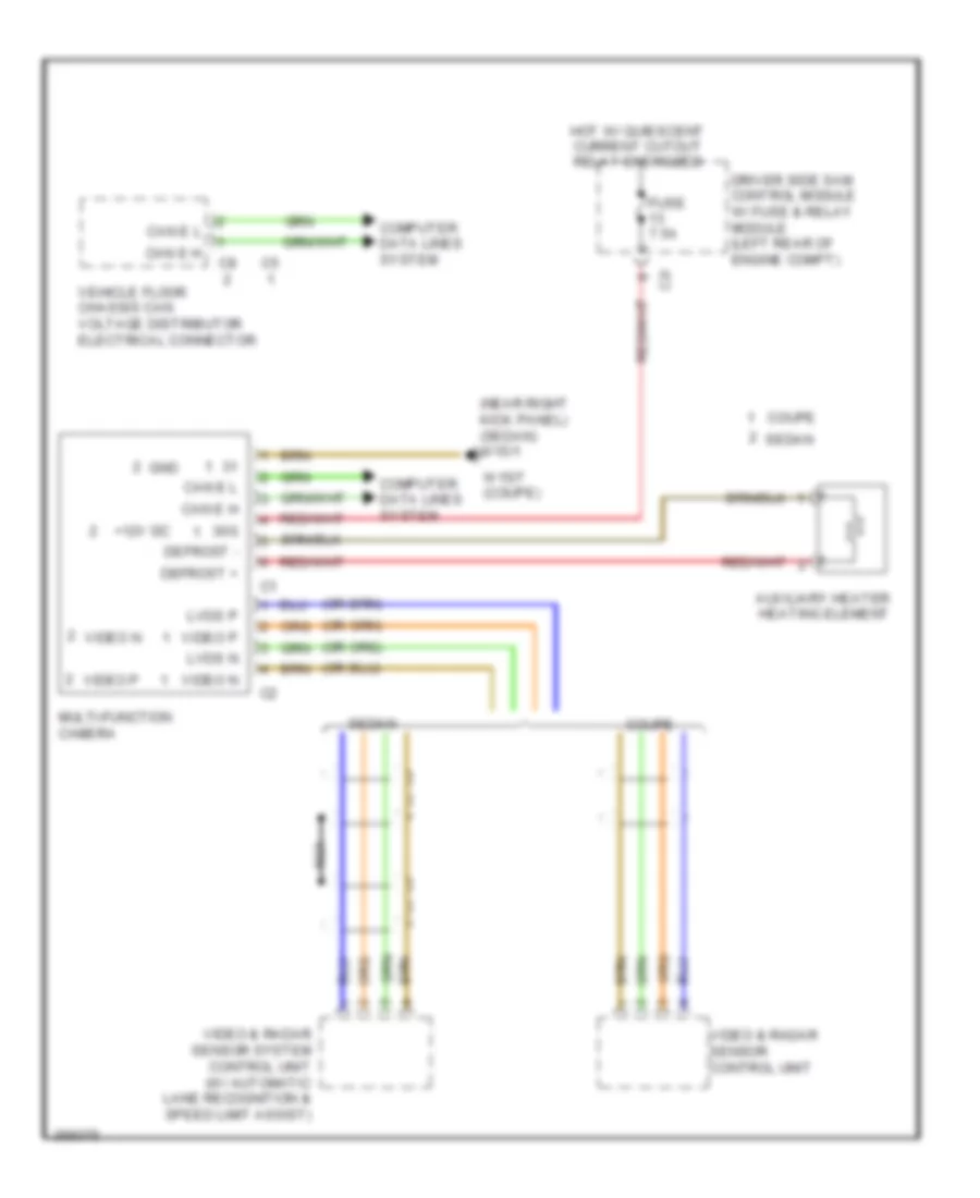
- Multi-function camera (if equipped)
- Right front reversible emergency tensioning retractor (if equipped) (on right front "b" pillar)
- Vehicle dynamics can voltage distributor electrical connector
- W/ esp basic
- W/ esp premium
- Yaw rate, lateral & longitudinal acceleration sensor
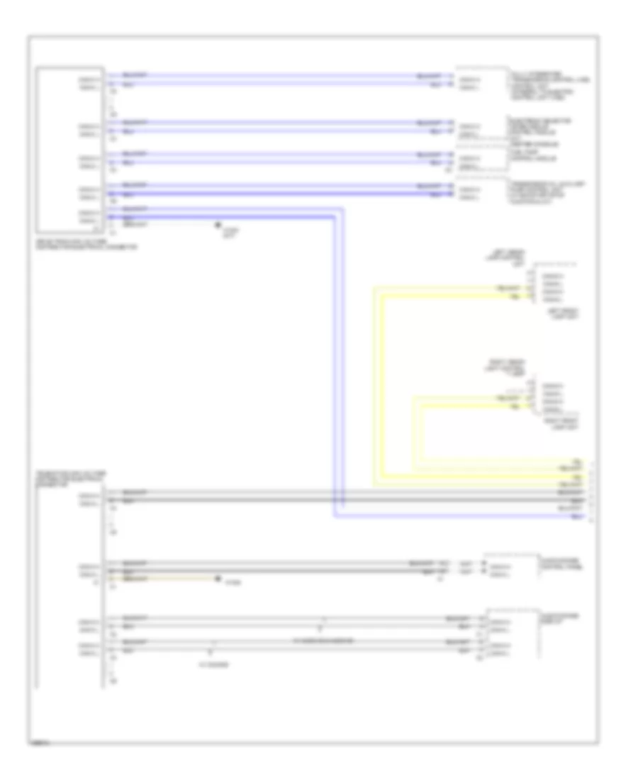
High/Low Bus Wiring Diagram, Sedan (1 of 5) for Mercedes-Benz E350 2011
List of elements for High/Low Bus Wiring Diagram, Sedan (1 of 5) for Mercedes-Benz E350 2011:
- Audio/comand control panel
- Audio/comand display
- Can-a h
- Can-a l
- Can-c h
- Can-c l
- Can-g h
- Can-g l
- Drive train can voltage distributor electrical connector
- Dvd player (w/ rear entertainment (dvd))
- Electronic selector lever module control module (center console)
- Electronic transmission control unit
- Fuel pump control module
- Fully integrated transmission control (vgs) control unit (integral to electric control unit (vgs))
- Intelligent servo module for direct select (if equipped) (transmission housing)
- Left front lamp unit
- Left rear display (w/ rear entertainment (dvd))
- Me-sfi (me) control module (center rear of engine compt)
- Module for direct select
- Right front lamp unit
- Right rear display (w/ rear entertainment (dvd))
- Telematics can voltage distributor electrical connector
- Transmission oil auxiliary pump control unit
- W/ eco start/stop function & a/t
- W/ electronic transmission control
- W/ intelligent servo
- W/o direct select & a/t
- W/o electronic transmission control
- W15/1 (near right kick panel)
- W15/5
- X138/1-c1
- X55/3-c9
- X55/4-c9
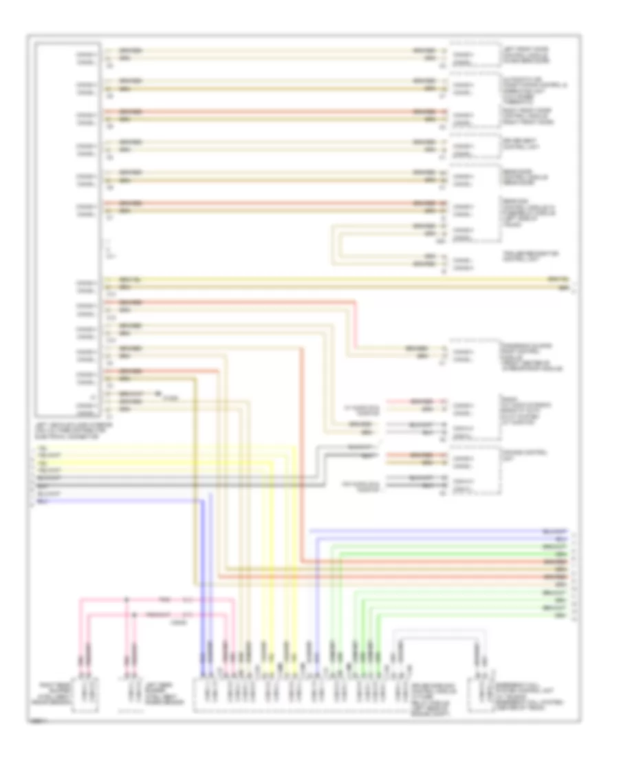
High/Low Bus Wiring Diagram, Sedan (2 of 5) for Mercedes-Benz E350 2011
List of elements for High/Low Bus Wiring Diagram, Sedan (2 of 5) for Mercedes-Benz E350 2011:
- (near left kick panel) w15/2
- C10
- C11
- C11c
- C12
- C13
- C18m
- C19i
- C20m
- C21m
- C22i
- C7i
- Can-a h
- Can-a l
- Can-b h
- Can-b l
- Can-d h
- Can-d l
- Can-e h
- Can-e l
- Can-g h
- Can-g l
- Comand control unit (if equipped)
- Driver seat control unit
- Driver side sam control module w/ fuse/ relay module (left rear of engine compt)
- Dynamic multicontour seat pneumatic pump (if equipped)
- Electrical power steering control unit (if equipped)
- Left front door control module (in driver's door)
- Left front dynamic multicontour seat control unit
- Left rear bumper intelligent radar sensor
- Left rear door control module (left rear door)
- Left vehicle floor interior can voltage distributor electrical connector
- Overhead control panel control unit (in overhead console)
- Panoramic sliding roof control module (front center of interior roof module)
- Radio (w/ audio 20 radio) radio w/ auto pilot system (w/ audio 50)
- Right rear bumper intelligent radar sensor
- Tailgate control unit (if equipped)
- Trailer recognition control module (if equipped)
- W/ audio 20 radio & radio 50
- W/ panoramic sliding roof
- W/ partially electric driver seat adjustment
- W/ partially electric front passenger seat adjustment
- W/ partially electric seat adjustment
- W/o audio 20 radio & radio 50
- W/o panoramic sliding roof
- W/o partially electric seat adjustment
- X172/2
- X24/7-c1
- X35/3-c1
- X55/3-c1
- X55/4
High/Low Bus Wiring Diagram, Sedan (3 of 5) for Mercedes-Benz E350 2011
List of elements for High/Low Bus Wiring Diagram, Sedan (3 of 5) for Mercedes-Benz E350 2011:
- C10
- C11
- C110
- C12
- C13
- C9i
- Can-b h
- Can-b l
- Can-e h
- Can-e l
- Front passenger seat control unit
- Keyless go control unit (if equipped)
- Left front reversible emergency tensioning retractor (if equipped) (on left front "b" pillar)
- Me-sfi (me) control module (except 3.0l turbo) (center rear of engine compt) cdi control module (3.0l turbo) (left rear of engine compt)
- Rear sam control module w/ fuse/relay module (left side of trunk)
- Rear seat heater control unit (if equipped)
- Right front door control module (right front door)
- Right front dynamic multicontour seat control unit
- Right rear door control module (right rear door)
- Right vehicle floor interior can voltage distributor electrical connector
- Special purpose vehicle multi-function control unit (w/ taxi electrical system)
- Stationary heater unit (if equipped) (right front engine compt)
- Tire pressure monitor control unit (if equipped)
- Vehicle floor chassis can voltage distributor electrical connector
- W/ fully electric seat adjustment w/ memory function
- W/ partially electric driver seat adjustment
- W/ partially electric front passenger seat adjustment
- W/o fully electric seat adjustment w/ memory function
- W15/2 (near left kick panel)
- Weight sensing system control unit (if equipped) (under right front seat)
- X1/60-c1
- X35/4-c1
- X55/3
- X55/4-c1
- X55/4-c2
High/Low Bus Wiring Diagram, Sedan (4 of 5) for Mercedes-Benz E350 2011
List of elements for High/Low Bus Wiring Diagram, Sedan (4 of 5) for Mercedes-Benz E350 2011:
- Airmatic w/ ads control module (if equipped) (under right side of dash)
- Automatic air conditioning control & operating unit (2 & 3 zones thermatic)
- Can-b h
- Can-b l
- Can-e h
- Can-e l
- Can-h h
- Can-h l
- Distronic electric controller unit (w/ distronic plus)
- Electronic ignition switch control unit
- Electronic stability program control unit
- Instrument cluster
- Multi-function camera (interior lights package, w/automatic lane recognition & w/ speed limit assist)
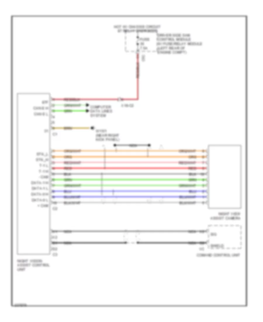
- Night vision assist control unit (if equipped)
- Parktronic control unit (if equipped)
- Premium electronic stability program control unit (w/ esp premium)
- Radar sensor control unit (w/ distronic & w/ blind spot assist)
- Right front reversible emergency tensioning retractor (if equipped) (on right front "b" pillar)
- Steering wheel heater control unit (ifequipped)
- Vehicle dynamics can voltage distributor electrical connector
- W/ esp basic
- W/ esp premium
- Yaw rate, lateral & longitudinal acceleration sensor (w/ esp premium)
High/Low Bus Wiring Diagram, Sedan (5 of 5) for Mercedes-Benz E350 2011
List of elements for High/Low Bus Wiring Diagram, Sedan (5 of 5) for Mercedes-Benz E350 2011:
- (or pnk)
- 3.0l turbo diesel
- 3.5l
- Can-e h
- Can-e l
- Can-i h
- Can-i l
- Cdi control module (left rear of engine compt)
- Left nitrogen oxides control unit
- Me-sfi (me) control module (center rear of engine compt)
- Nitrogen oxides control unit downstream of diesel particulate filter (3.5l)
- Nitrogen oxides control unit downstream of scr catalytic converter
- Pnk
- Potential distributor electrical connector (can i)
- Right nitrogen oxides control unit
- W18
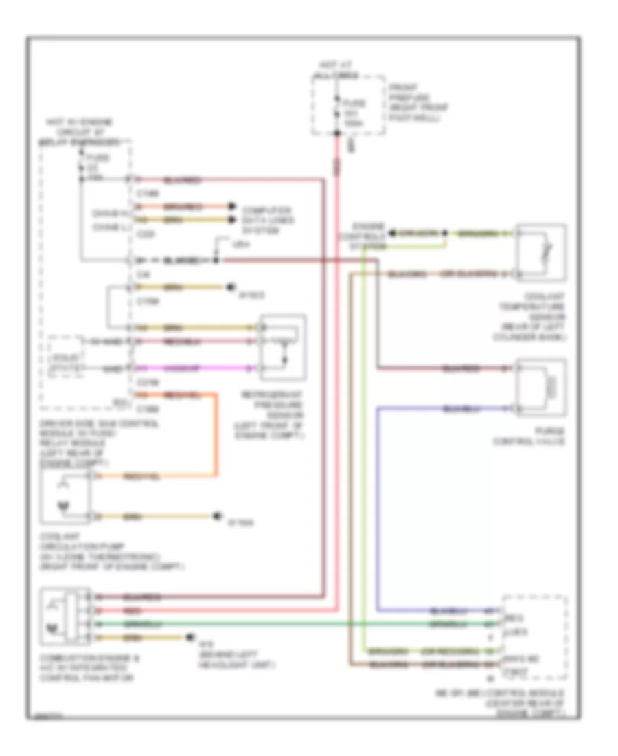
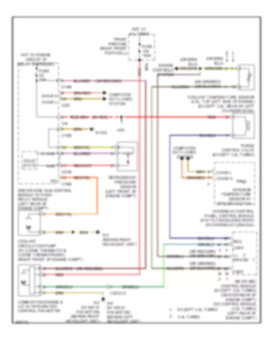
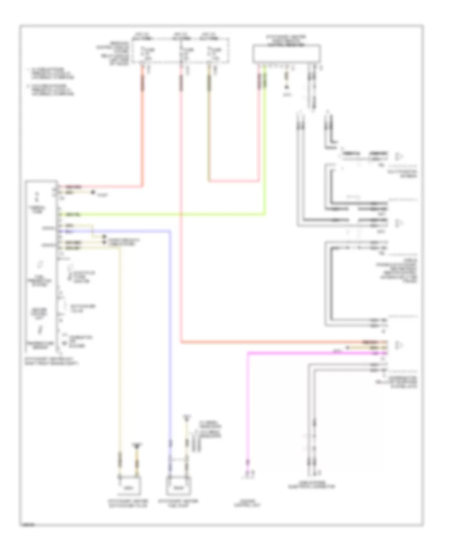
COOLING FAN
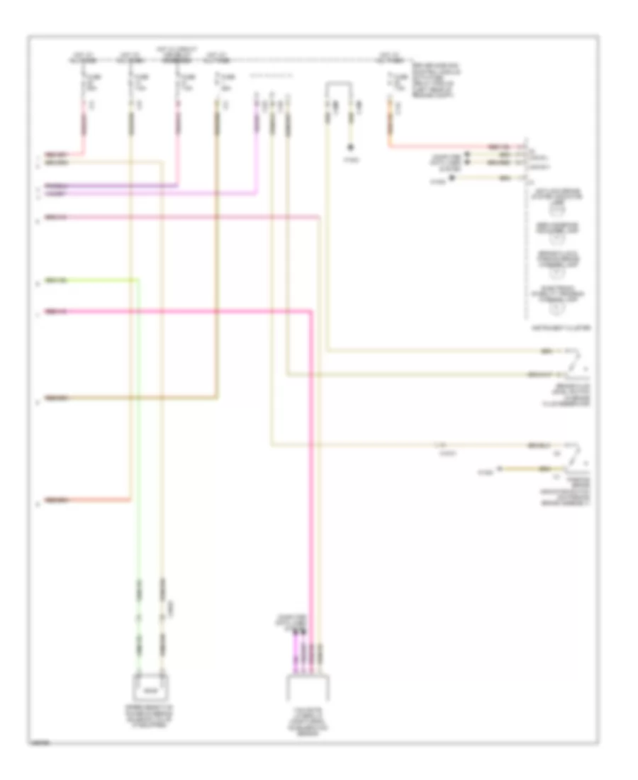
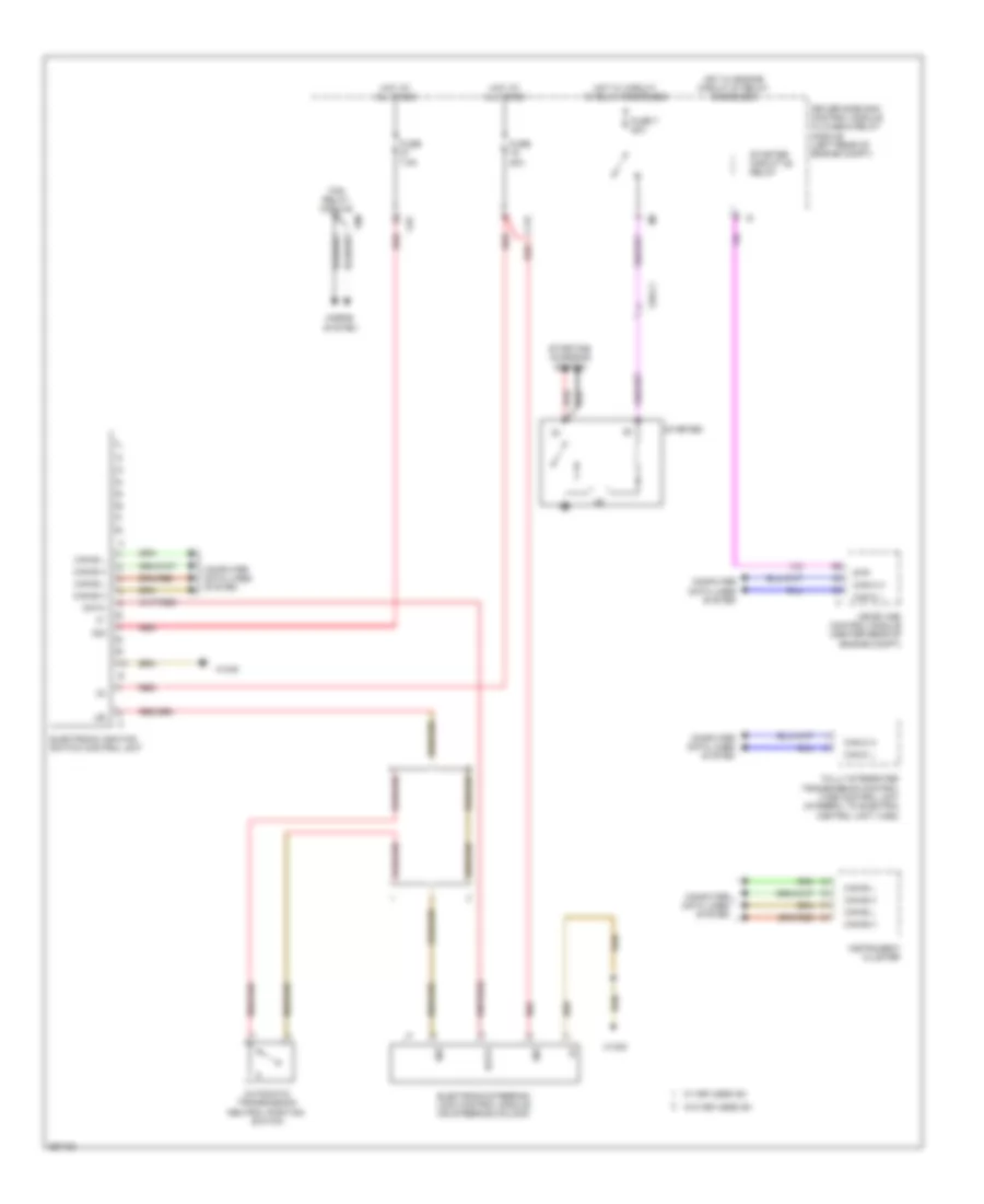
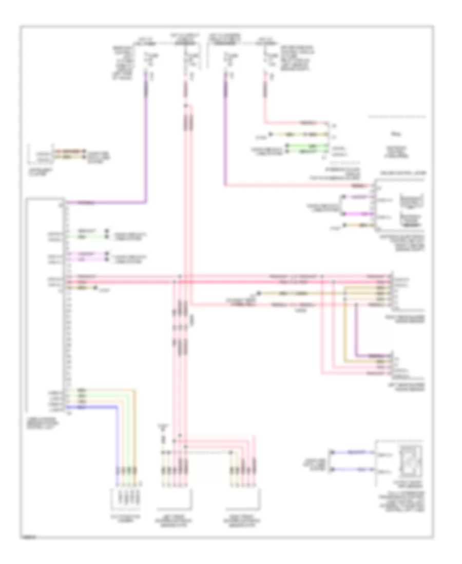
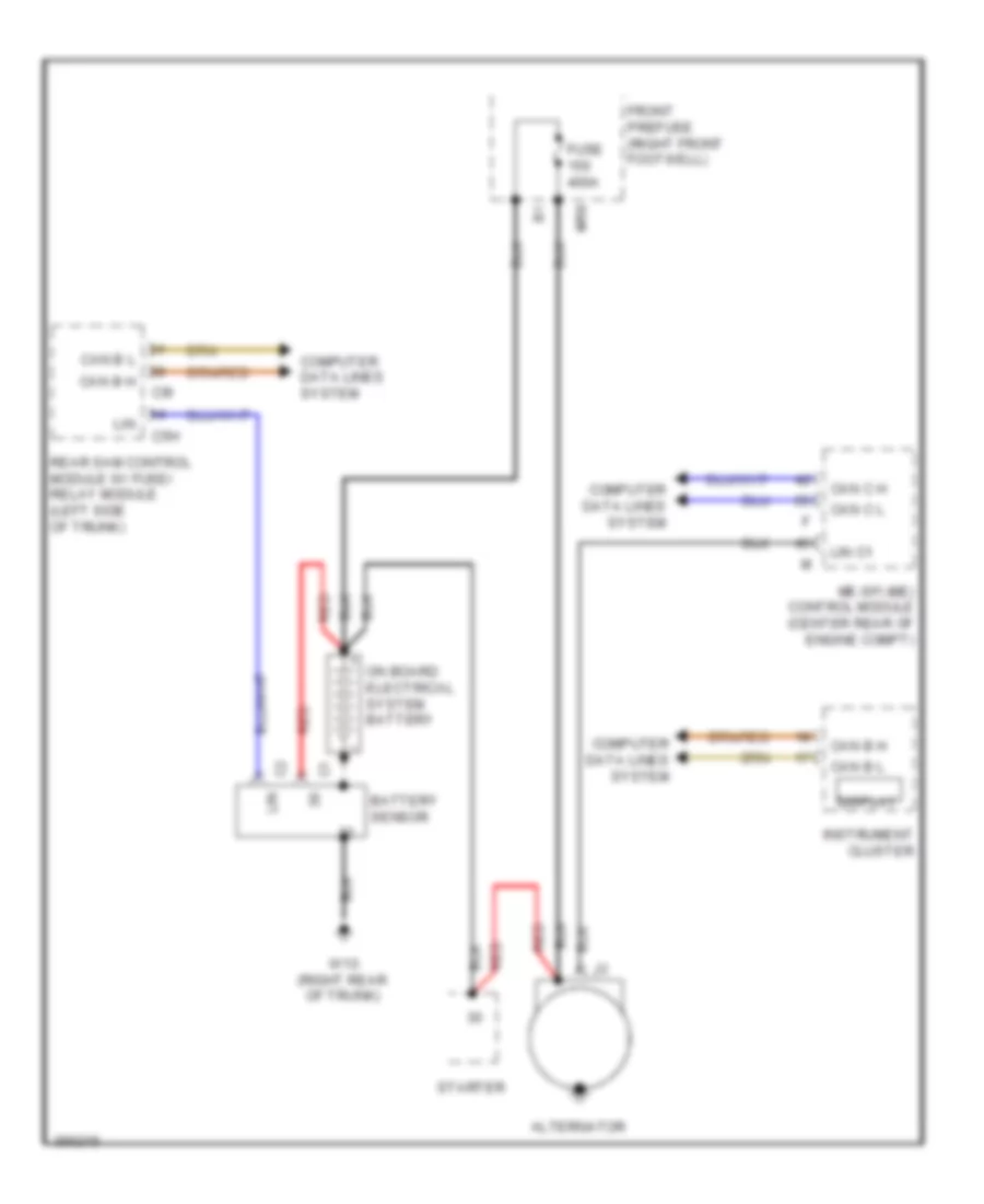
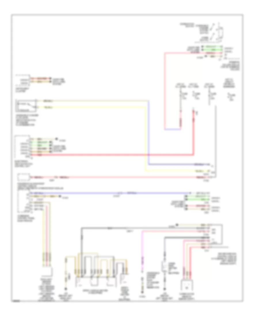
Cooling Fan Wiring Diagram, Coupe for Mercedes-Benz E350 2011
List of elements for Cooling Fan Wiring Diagram, Coupe for Mercedes-Benz E350 2011:
- 5v khd
- C14m
- C15m
- C18m
- C21m
- C22i
- C4i
- Can-b h
- Can-b l
- Combustion engine & a/c w/ integrated control fan motor
- Computer data lines system
- Coolant circulation pump (w/ 3-zone thermotronic) (right front of engine compt)
- Coolant temperature sensor (rear of left cylinder bank)
- Driver side sam control module w/ fuse/ relay module (left rear of engine compt)
- Engine controls system
- Front prefuse (right front footwell)
- Fuse 100a
- Fuse 15a
- Hot at all times
- Hot w/ engine circuit 87 relay energized
- Khd
- Lues
- Me-sfi (me) control module (center rear of engine compt)
- Mr1
- Nwg m2
- Purge control valve
- Red
- Refrigerant pressure sensor (left front of engine compt)
- Reg
- Sig
- Solid state
- Tmot
- Usa
- W16/3
- W16/4
- W9 (behind left headlight unit)
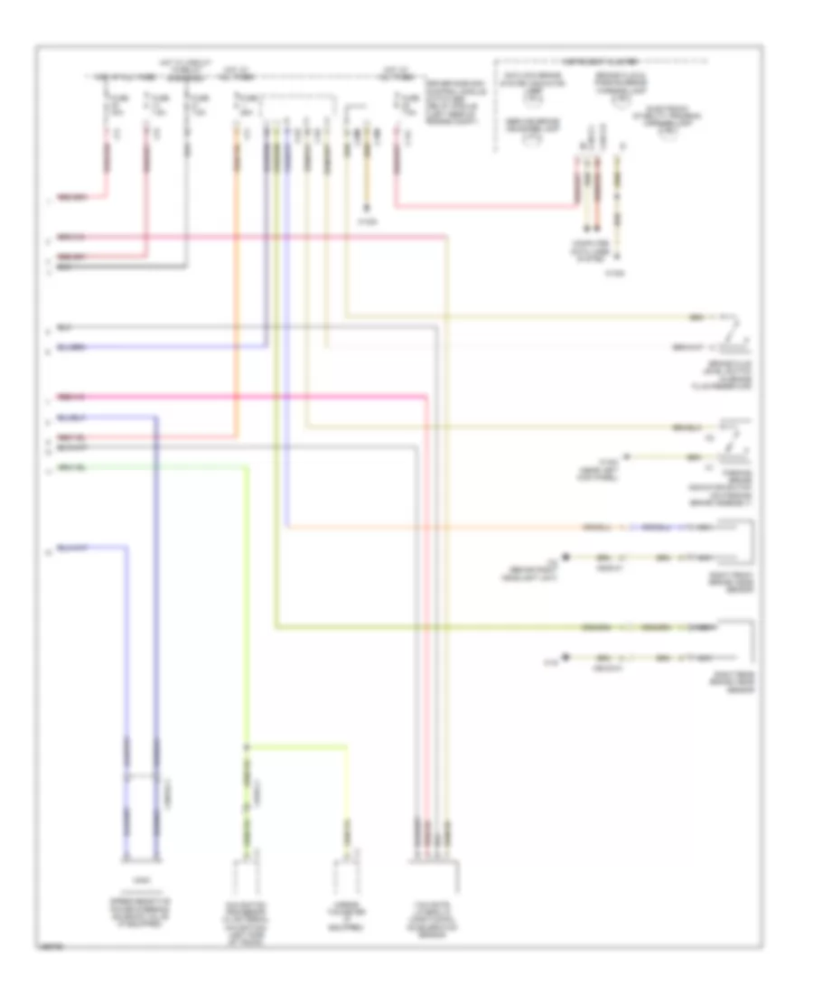
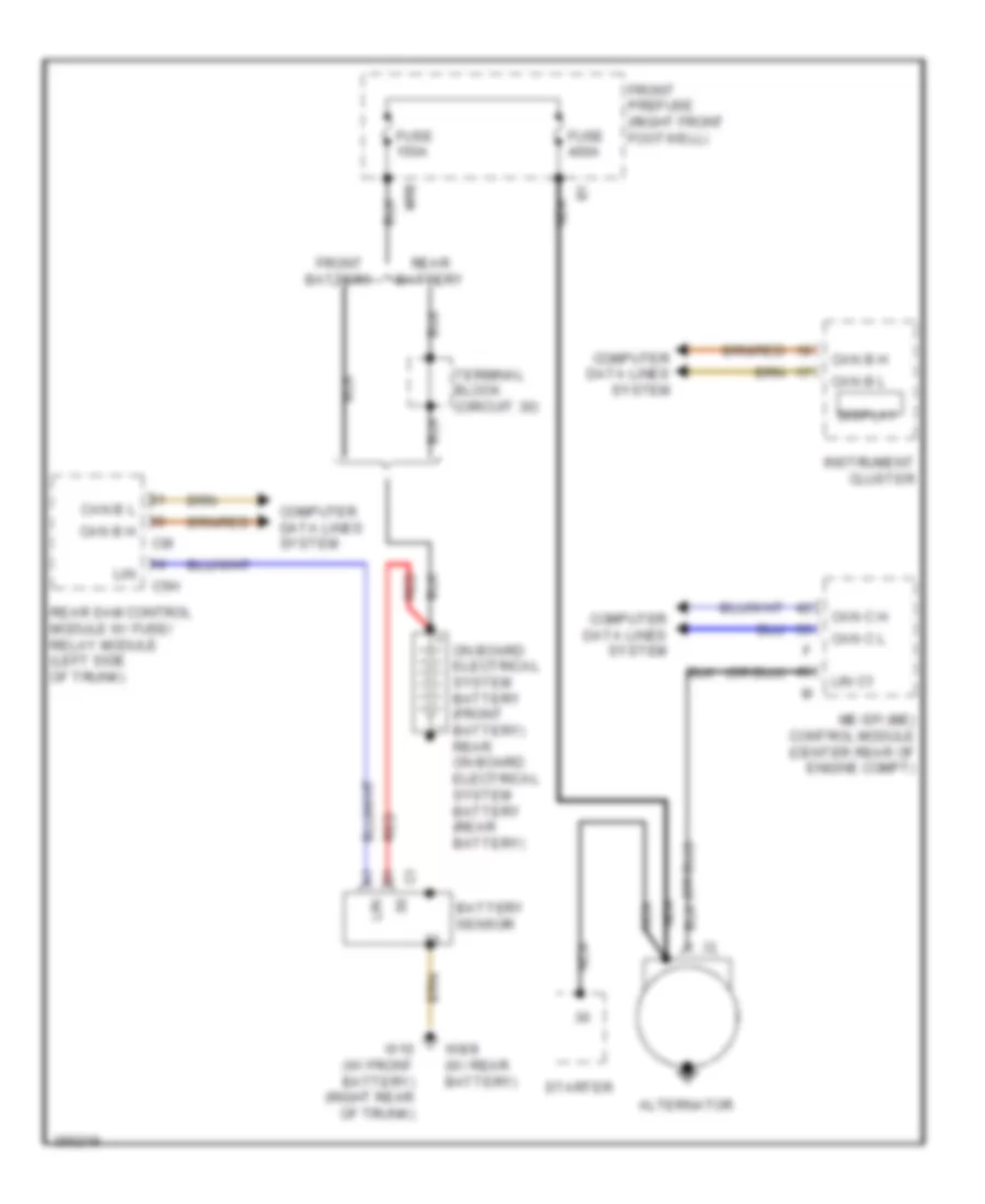
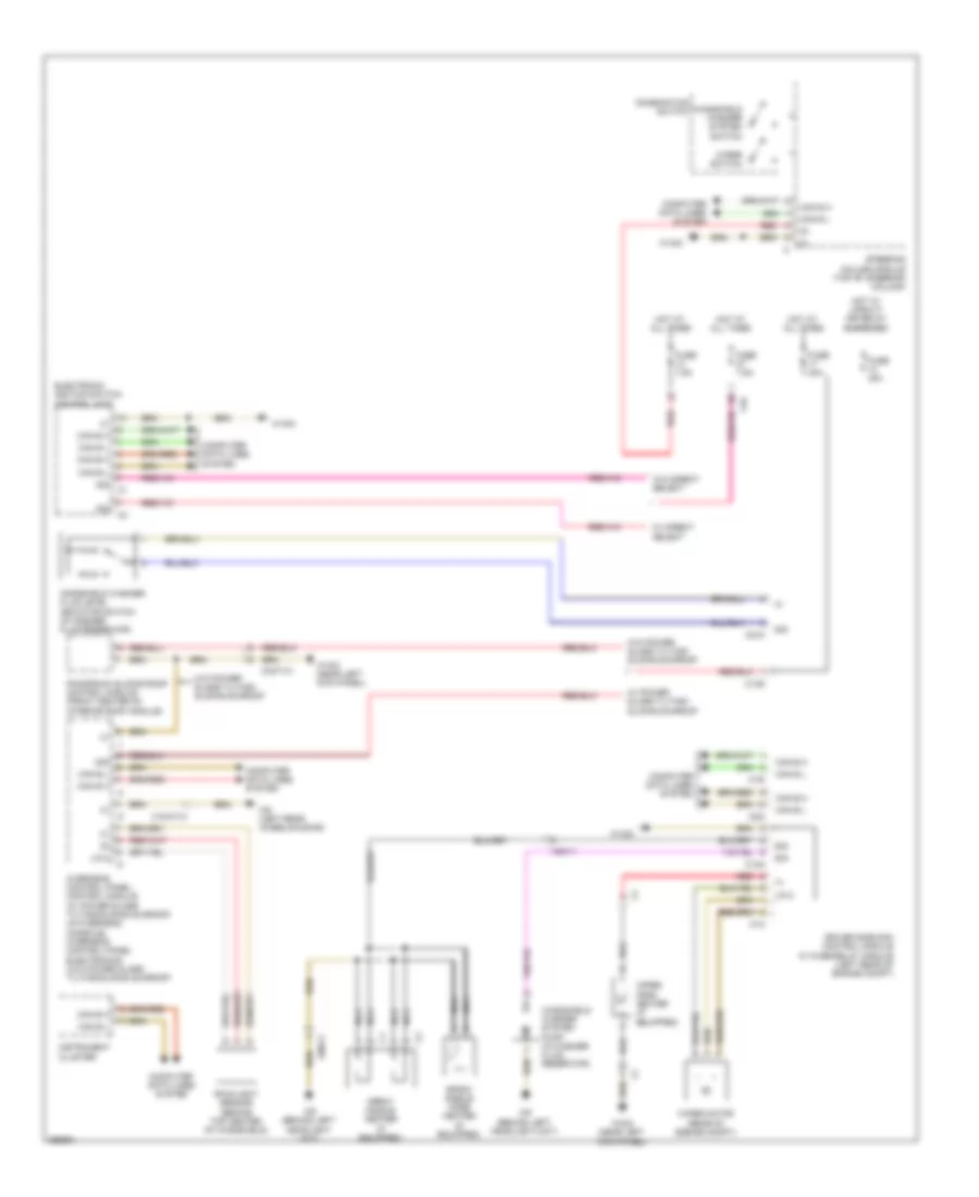
Cooling Fan Wiring Diagram, Sedan for Mercedes-Benz E350 2011
List of elements for Cooling Fan Wiring Diagram, Sedan for Mercedes-Benz E350 2011:
- (-) nwg m2
- (or red)
- 3.0l turbo
- 5v khd
- C14m
- C15m
- C18m
- C21m
- C22i
- C4i
- Can-b h
- Can-b l
- Combustion engine & a/c w/ integrated control fan motor
- Computer data lines system
- Coolant circulation pump (w/ 2-zone thermatic & 3-zone thermotronic) (right front of engine compt)
- Coolant temperature sensor (3.0l: top left side of engine) (except 3.0l: rear of left cylinder bank)
- Driver side sam control module w/ fuse/ relay module (left rear of engine compt)
- Engine controls system
- Except 3.0l turbo
- Front prefuse (right front footwell)
- Fuse 100a
- Fuse 15a
- Hot at all times
- Hot w/ engine circuit 87 relay energized
- Interior temperature sensor w/ integrated fan
- Khd
- Lues
- Me-sfi (me) control module (except 3.0l turbo) (center rear of engine compt) cdi control module (3.0l turbo) (left rear of engine compt)
- Mr4
- Overhead control panel control module (w/o tilting/sliding roof) (in overhead console)
- Purge control valve (except 3.0l turbo)
- Red
- Refrigerant pressure sensor (left front of engine compt)
- Reg
- Sig
- Solid state
- Tmot
- Usa
- W15/5
- W2 (behind right headlight unit)
- W2 (w/ 800 w fan motor) (behind right headlight unit)
- W9 (w/ 650 w fan motor) (behind left headlight unit)
- X25/2-c1
CRUISE CONTROL
3.0L TURBO DIESEL
3.0L Turbo Diesel, Cruise Control Wiring Diagram for Mercedes-Benz E350 2011
List of elements for 3.0L Turbo Diesel, Cruise Control Wiring Diagram for Mercedes-Benz E350 2011:
- Accel/ set
- Accelerator pedal sensor (top of accelerator pedal assembly)
- C12i
- C14i
- C4i
- Can b h
- Can b l
- Can e h
- Can e l
- Can h h
- Can h l
- Cdi control module (left rear of engine compt)
- Computer data lines system
- Cruise control lever
- Decel/ set
- Distronic control (if equipped)
- Driver side sam control module w/ fuse/ relay module (left rear of engine compt)
- Front sam control unit w/ fuse & relay module
- Fuse 5a
- Fuse 7.5a
- Fuse 7.5a 5a
- Hot at all times
- Hot w/ circuit 15 relay energized
- Ind
- Instrument cluster
- Left front bumper inner radar sensor
- Left rear bumper outer radar sensor (blind spot assist)
- M (+)
- M (-)
- Off
- Poti (+)
- Poti (-)
- Poti sig
- Radar sensors control unit
- Rear sam control module w/ fuse & relay module (left side of trunk)
- Red
- Resume
- Right front bumper inner radar sensor (distronic plus)
- Right rear bumper outer radar sensor (blind spot assist)
- Sh high
- Sh low
- Sp1m
- Sp1s
- Sp2m
- Sp2s
- Speedtronic light emitting diode (except usa)
- Speedtronic switch (except usa)
- Steering column module (top of steering column)
- Sv high
- Sv low
- Throttle valve actuator
- U pwg
- W/ active park assist & pedestrian protection
- W/ active park assist w/o pedestrian protection
- W/ pedestrian protection w/o active park assist
- W/o park assist
- W15/1 (near right kick panel)
- W15/5
- W2 (behind right headlight unit)
- W3/1 (right front of engine compt)
- W7 (on right rear wheelwell)
- X172/2-c1
- X26/38-c1
- X26/38-c2
- X26/38-c3
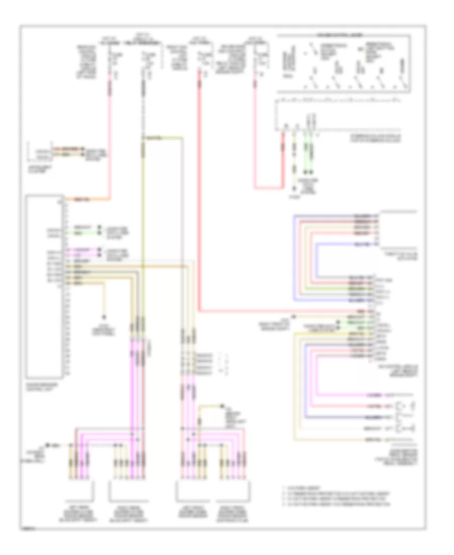
3.0L Turbo Diesel, Electronic Accelerator/Cruise/Idle Speed Control Wiring Diagram, Sedan for Mercedes-Benz E350 2011
List of elements for 3.0L Turbo Diesel, Electronic Accelerator/Cruise/Idle Speed Control Wiring Diagram, Sedan for Mercedes-Benz E350 2011:
- (integral to electric control unit (vgs)) fully integrated transmission control (vgs) control unit
- (top of steering column) steering column module
- C2i
- Can b h
- Can b l
- Can c h
- Can c l
- Can h h
- Can h l
- Can-e h
- Can-e l
- Computer data lines system
- Cruise control lever
- Distronic control (if equipped)
- Distronic control unit
- Distronic electric controller unit (front center engine compt)
- Distronic radar sensor
- Driver side sam control module w/ fuse/relay module (left rear of engine compt)
- Fuse 7.5a
- Hot w/ chassis circuit 87 relay energized
- Instrument cluster
- Output shaft rpm sensor
- W2 (behind right headlight unit)
3.5L
3.5L, Cruise Control Wiring Diagram for Mercedes-Benz E350 2011
List of elements for 3.5L, Cruise Control Wiring Diagram for Mercedes-Benz E350 2011:
- (+) sv
- (behind right headlight unit) (sedan) w2
- (coupe)
- (or pnk/red)
- (or red)
- (or sp2m)
- (or sp2s)
- (sedan)
- Accel/ set
- Accelerator pedal sensor (top of accelerator pedal assembly)
- C12i
- C14i
- C4i
- Can b h
- Can b l
- Can e h
- Can e l
- Can h h
- Can h l
- Can-e h
- Can-e l
- Computer data lines system
- Coupe
- Cruise control lever
- Dcm
- Dcp
- Decel/ set
- Distronic control (if equipped)
- Driver side sam control module w/ fuse/ relay module (left rear of engine compt)
- Fuse 5a
- Fuse 7.5a
- Fuse 7.5a 5a
- Hot at all times
- Hot w/ circuit 15 relay energized
- Ind
- Instrument cluster
- Ip1s
- Ip2s
- Ipm
- Left front bumper inner radar sensor
- Left rear bumper outer radar sensor (blind spot assist)
- Me-sfi (me) control module (center rear of engine compt)
- Off
- Radar sensors control unit
- Rear sam control module w/ fuse & relay module (left side of trunk)
- Red
- Resume
- Right front bumper inner radar sensor (distronic plus)
- Right rear bumper outer radar sensor (blind spot assist)
- Sedan
- Sedan w/ active park assist & pedestrian protection
- Sedan w/ active park assist w/o pedestrian protection
- Sedan w/ pedestrian protection w/o active park assist
- Sedan w/o park assist
- Sh high
- Sh low
- Sp1m
- Sp1s
- Sp2m
- Sp2s
- Speedtronic light emitting diode (except usa)
- Speedtronic switch (except usa)
- Steering column module (top of steering column)
- Sv high
- Sv low
- Throttle valve actuator
- U_pwg1
- W15/1 (sedan) (near right kick panel)
- W15/5
- W15/7 (coupe)
- W16/5
- W7 (sedan) (on right rear wheelwell)
- W7/1 (coupe)
- X172/1
- X172/2
- X172/2-c1
- X26/38-c1
- X26/38-c2
- X26/38-c3
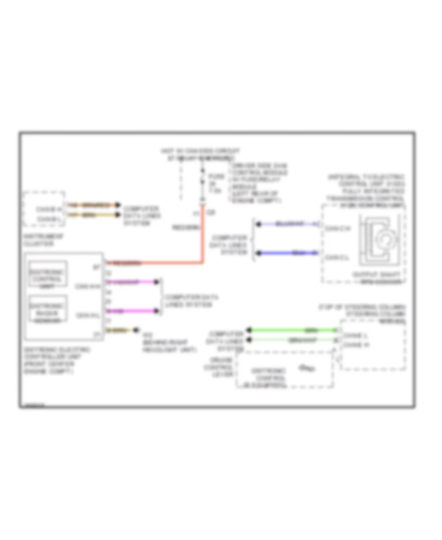
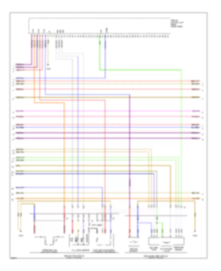
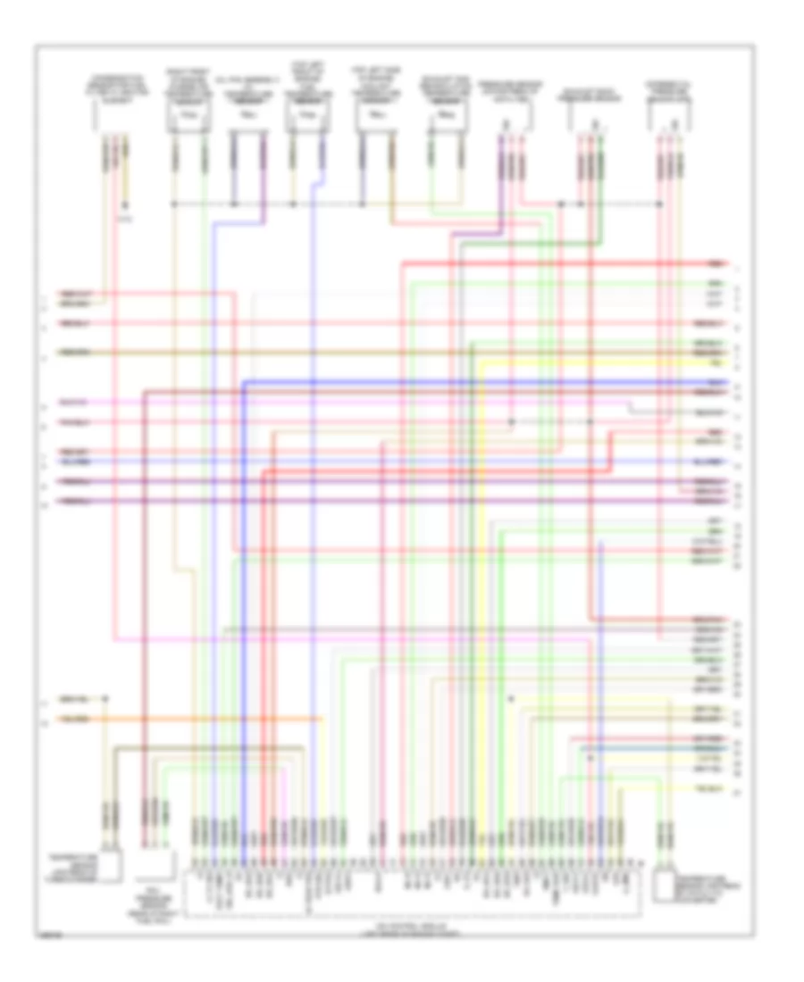
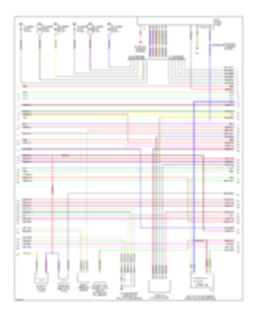
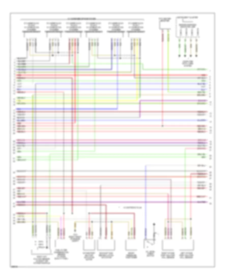
3.5L, Electronic Accelerator/Cruise/Idle Speed Control Wiring Diagram, Coupe for Mercedes-Benz E350 2011
List of elements for 3.5L, Electronic Accelerator/Cruise/Idle Speed Control Wiring Diagram, Coupe for Mercedes-Benz E350 2011:
- C12i
- C14i
- C2i
- C5c
- Can b h
- Can b l
- Can c h
- Can c l
- Can e h
- Can e l
- Can h h
- Can h l
- Can s h
- Can s l
- Computer data lines system
- Cruise control lever
- Distronic control (if equipped)
- Distronic control unit
- Distronic electronic controller unit (front center engine compt)
- Distronic radar sensor
- Driver side sam control module w/ fuse/ relay module (left rear of engine compt)
- Fully integrated transmission control (vgs) control unit (integral to electric control unit (vgs))
- Fuse 5a
- Fuse 7.5a
- Hot at all times
- Hot w/ chassis circuit 87 relay energized
- Hot w/ circuit 15 relay energized
- Instrument cluster
- Left front bumper distronic sensor (dtr)
- Left rear bumper radar sensor
- Lvds n
- Lvds p
- Multifunction camera
- Output shaft rpm sensor
- Pnk
- Rear sam control unit w/ fuse & relay module (left side of trunk)
- Right front bumper distronic sensor (dtr)
- Right rear bumper radar sensor
- Steering column module (top of steering column)
- Video & radar sensor system control unit
- Video n
- Video p
- W15/5
- W15/7
- W7 (on right rear wheelwell)
- X26/38
- X35/28
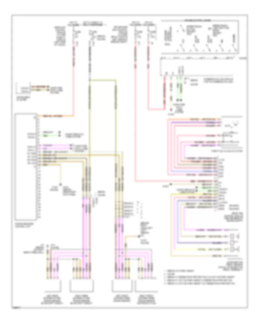
3.5L, Electronic Accelerator/Cruise/Idle Speed Control Wiring Diagram, Sedan for Mercedes-Benz E350 2011
List of elements for 3.5L, Electronic Accelerator/Cruise/Idle Speed Control Wiring Diagram, Sedan for Mercedes-Benz E350 2011:
- (integral to electric control unit (vgs)) fully integrated transmission control (vgs) control unit
- (top of steering column) steering column module
- C2i
- Can b h
- Can b l
- Can c h
- Can c l
- Can h h
- Can h l
- Can-e h
- Can-e l
- Computer data lines system
- Cruise control lever
- Distronic control (if equipped)
- Distronic control unit
- Distronic electric controller unit (front center engine compt)
- Distronic radar sensor
- Driver side sam control module w/ fuse/relay module (left rear of engine compt)
- Fuse 7.5a
- Hot w/ chassis circuit 87 relay energized
- Instrument cluster
- Output shaft rpm sensor
- W2 (behind right headlight unit)
DEFOGGERS
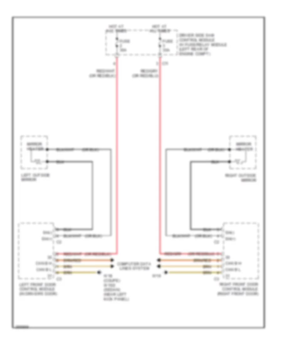
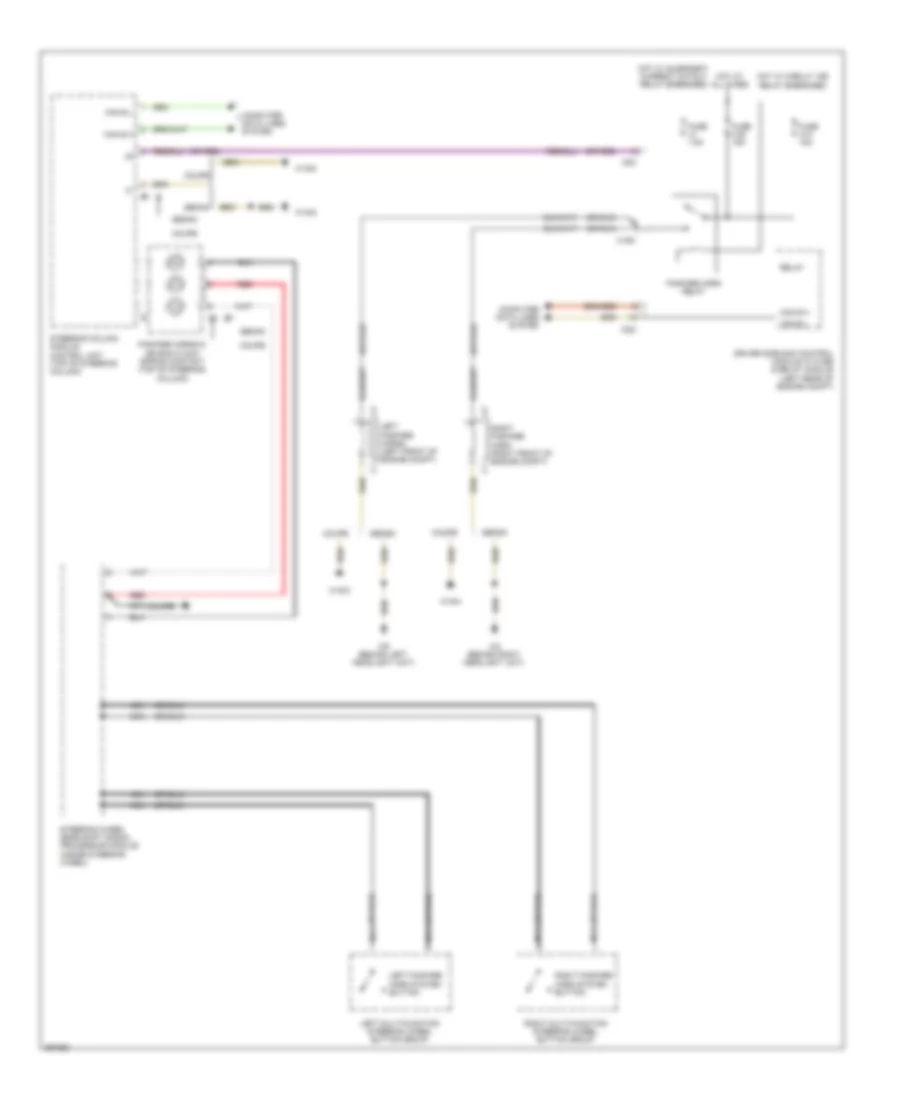
Heated Mirrors Wiring Diagram for Mercedes-Benz E350 2011
List of elements for Heated Mirrors Wiring Diagram for Mercedes-Benz E350 2011:
- C7i
- Can b h
- Can b l
- Computer data lines system
- Driver side sam control module w/ fuse/relay module (left rear of engine compt)
- Fuse 30a
- Hot at all times
- Left front door control module (in driver's door)
- Left outside mirror
- Mirror heater
- Right front door control module (right front door)
- Right outside mirror
- Sh(+)
- Sh(-)
- W18 (coupe) w15/2 (sedan) (near left kick panel)
- W19
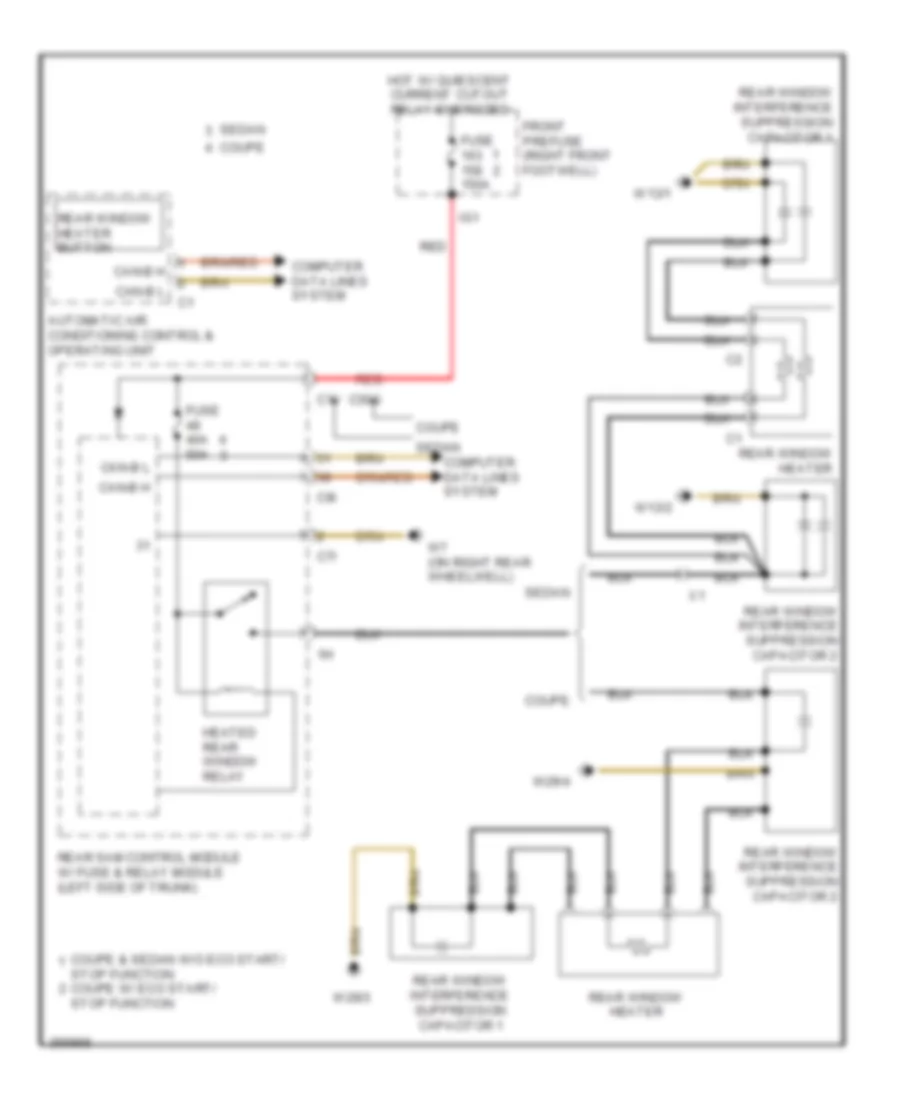
Rear Defogger Wiring Diagram for Mercedes-Benz E350 2011
List of elements for Rear Defogger Wiring Diagram for Mercedes-Benz E350 2011:
- Automatic air conditioning control & operating unit
- C1v
- C30g
- C7i
- C9i
- Can-b h
- Can-b l
- Computer data lines system
- Coupe
- Coupe & sedan w/o eco start/
- Front prefuse (right front footwell)
- Fuse 150a
- Fuse 40a 50a
- Heated rear window relay
- Hot w/ quiescent current cutout relay energized
- Ig1
- Rear sam control module w/ fuse & relay module (left side of trunk)
- Rear window heater
- Rear window heater button
- Rear window interference suppression capacitor 1
- Rear window interference suppression capacitor 2
- Red
- Sedan
- Stop function coupe w/ eco start/ stop function
- W13/1
- W13/2
- W29/3
- W29/4
- W7 (on right rear wheelwell)
ELECTRONIC POWER STEERING
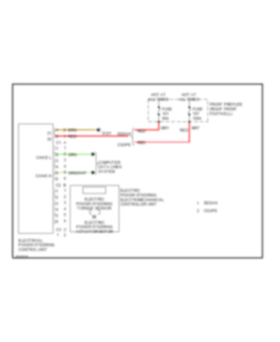
Electronic Power Steering Wiring Diagram for Mercedes-Benz E350 2011
List of elements for Electronic Power Steering Wiring Diagram for Mercedes-Benz E350 2011:
- Can-e h
- Can-e l
- Computer data lines system
- Coupe
- Electric power steering actuator motor
- Electric power steering electromechanical controller unit
- Electric power steering torque sensor
- Electrical power steering control unit
- Front prefuse (right front footwell)
- Fuse 100a
- Fuse 60a
- Hot at all times
- Mr1
- Mr7 red
- Red
- Sedan
- W2/1
Power Steering Column Wiring Diagram, Coupe for Mercedes-Benz E350 2011
List of elements for Power Steering Column Wiring Diagram, Coupe for Mercedes-Benz E350 2011:
- Accelerate & set switch
- Accept/terminate phone call button
- Back & voice control system off button
- Button + & - setting of specific functions & volume control
- C5c
- Can-e h
- Can-e l
- Combination switch
- Computer data lines system
- Cruise control lever
- Decelerate & set switch
- Distronic control (if equipped)
- Driver side sam control module w/ fuse/relay module (left rear of engine compt)
- Fanfare horns & air bag clock spring contact (top of steering column)
- Fuse 7.5a
- Head lamp flasher/high beam switch
- Hot at all times
- Indicator switch
- Left fanfare horn system button
- Left multi-function steering wheel button group
- Low beam switch
- Mute button
- Nca
- Off switch
- Ok button
- Red
- Resume from memory switch
- Right fanfare horn system button
- Right multi-function steering wheel button group
- Scroll forward/ back button
- Speedtronic light emitting diode
- Speedtronic switch (canada)
- Steering angle sensor
- Steering column adjustment switch
- Steering column module (top of steering column)
- Steering wheel downshift button (if equipped)
- Steering wheel gear shift signal processing module (inside steering wheel)
- Steering wheel upshift button (if equipped)
- System selection button
- Turn signal lamp switch
- Voice control system on button
- W15/5
- Windshield washer system switch
- Wipe switch
Power Steering Column Wiring Diagram, Sedan for Mercedes-Benz E350 2011
List of elements for Power Steering Column Wiring Diagram, Sedan for Mercedes-Benz E350 2011:
- (if equipped) steering wheel heater control unit
- (top of steering column) steering column module control unit
- +, -
- Accelerate & set switch
- Accept/terminate phone call button
- Aldw+
- Aldw-
- Back & voice control system off button
- Button + & - setting of specific functions & volume control
- C5c
- Can-b h
- Can-b l
- Can-e h
- Can-e l
- Combination switch
- Computer data lines system
- Cruise control lever
- Decelerate & set switch
- Direct select lever (if equipped)
- Distronic control (if equipped)
- Driver side sam control module w/ fuse/relay module (left rear of engine compt)
- Fanfare horns & air bag clock spring contact (top of steering column)
- Fuse 7.5a
- Gnd
- Head lamp flasher/high beam switch
- Heating element temperature sensor (if equipped)
- Hot at all times
- Indicator switch
- Left fanfare horn system button
- Left multi-function steering wheel button group
- Low beam switch
- Lsp+
- Lsp-
- Mute
- Mute button
- Nca
- Ntc +
- Ntc -
- Off switch
- Ok button
- R, return
- Red
- Resume from memory switch
- Right fanfare horn system button
- Right multi-function steering wheel button group
- Scroll forward/ back button
- Speedtronic light emitting diode (canada)
- Speedtronic switch (canada)
- Steering angle sensor
- Steering column adjustment & steering wheel heater switch
- Steering column adjustment switch
- Steering wheel downshift button (if equipped)
- Steering wheel gear shift signal processing module (inside steering wheel)
- Steering wheel heater heating element (if equipped)
- Steering wheel heater indicator lamp (if equipped)
- Steering wheel heater switch (if equipped)
- Steering wheel upshift button (if equipped)
- Steering wheel vibration motor (w/ automatic lane recognition)
- System selection button
- Tel
- Turn signal lamp switch
- U-mfl-r
- U-mll-l
- Voice control system on button
- W15/5
- Windshield washer system switch
- Wipe switch
ELECTRONIC SUSPENSION
Electronic Suspension Wiring Diagram (1 of 2) for Mercedes-Benz E350 2011
List of elements for Electronic Suspension Wiring Diagram (1 of 2) for Mercedes-Benz E350 2011:
- (or nca)
- (sedan) airmatic valve unit
- +5v
- Adaptive damping system control unit (coupe) airmatic control unit (sedan)
- Air compressor motor
- Airmatic compressor unit (sedan) (lower left front of engine compt)
- Airmatic pressure reduction valve
- Ans/ablas sig
- C12i
- C15h
- Central reservoir filling valve
- Coupe
- Ds zent sp gnd
- Ds zent sp sig
- Ds zent sp vsg
- Fb hal niv sig
- Fb har niv sig
- Fb val niv sig
- Fb versg
- Fb war niv sig
- Fuse 15a
- Gnd
- H side
- Hot at all times
- L side
- Left front level control valve
- Left rear axle damping valve unit (left rear axle)
- Left rear body lateral acceleration sensor
- Left rear level control valve
- Left rear level sensor
- Nca
- Pnk/red
- Pressure sensor
- Rear sam control module w/ fuse & relay module (left side of trunk)
- Right front level control valve
- Right rear axle damping valve unit (right rear axle)
- Right rear level valve
- Rkps
- Rkpv
- Sedan
- Sig
- Vkps
- Vkpv
- W15/1 (sedan) (near right kick panel)
- W15/7 (coupe)
- W6/4
- X62/32-c1
- X62/32-c3
Electronic Suspension Wiring Diagram (2 of 2) for Mercedes-Benz E350 2011
List of elements for Electronic Suspension Wiring Diagram (2 of 2) for Mercedes-Benz E350 2011:
- +5v
- Adaptive damping system control unit (coupe) airmatic control unit (sedan)
- Airmatic relay (sedan) (left rear of engine compt)
- Can-e h
- Can-e l
- Computer data lines system
- Coupe
- Front electrical prefuse box (sedan)
- Fuse 60a
- Gnd
- H side
- Hot at all times
- L side
- Left front axle damping valve unit (left front axle)
- Left front body lateral acceleration sensor (left side of engine compt, on wheelwell)
- Left front level sensor (left front wheelwell)
- Nca
- Pnk/red
- Red
- Right front axle damping valve unit (right front axle)
- Right front body lateral acceleration sensor (right side of engine compt, on wheelwell)
- Right front level sensor (right front wheelwell)
- Right rear level sensor
- Sedan
- Sig
- X62/33-c1
- X62/33-c3
- X62/7
- X62/7-c2
ENGINE ACCESSORIES
Stationary Heater Wiring Diagram, Coupe for Mercedes-Benz E350 2011
List of elements for Stationary Heater Wiring Diagram, Coupe for Mercedes-Benz E350 2011:
- Ant
- C11t
- C14i
- C15h
- Can b h
- Can b l
- Comand control unit
- Combustion air blower
- Compensator/ cellular telephone system umts
- Computer data lines system
- Fuel preheating system
- Fuse 20a
- Fuse 5a
- Fuse 7.5a
- Glow plug flame monitor
- Heater control unit
- Hot at all times
- Mobile phone & stationary heater radio remote control antenna splitter (trunk)
- Mobile phone electrical connector
- Multi-function antenna
- Nca
- Preinstallation w/ universal interface
- Rear sam control module w/fuse/ relay module (left side of trunk)
- Stationary heater fuel pump
- Stationary heater radio remote control receiver
- Stationary heater switchover valve
- Stationary heater unit (right front engine compt)
- Sth
- Switchover valve
- Tel
- Temperature sensor
- Thermal fuse
- W/ mobile phone
- W/ xenon headlamps
- W/o mobile phone
- W/o xenon headlamps x62/33-c1
- W15/7
- W7/1
- X62/33-c2
Stationary Heater Wiring Diagram, Sedan for Mercedes-Benz E350 2011
List of elements for Stationary Heater Wiring Diagram, Sedan for Mercedes-Benz E350 2011:
- (behind right head- light unit) w2
- Ant
- C14i
- C15h
- Can b h
- Can b l
- Combustion air blower
- Computer data lines system
- Fuel preheating system
- Fuse 20a
- Fuse 7.5a
- Glow plug flame monitor
- Heater control unit
- Hot at all times
- Mobile phone & stationary heater radio remote control antenna splitter (trunk)
- Multi-function antenna
- Nca
- Rear sam control module w/fuse/ relay module (left side of trunk)
- Stationary heater fuel pump
- Stationary heater radio remote control receiver
- Stationary heater switchover valve
- Stationary heater unit (rigth front engine compt)
- Switchover valve
- Temperature sensor
- Tes
- Thermal fuse
- W/ mobile phone
- W/o mobile phone
- W18
- W19
- W2 (behind right headlight unit)
- X62/33-c2
ENGINE PERFORMANCE
3.0L TURBO DIESEL
3.0L Turbo Diesel, Engine Performance Wiring Diagram (1 of 7) for Mercedes-Benz E350 2011
List of elements for 3.0L Turbo Diesel, Engine Performance Wiring Diagram (1 of 7) for Mercedes-Benz E350 2011:
- (-)
- 30z
- 87m
- Accelerator pedal sensor (top of accelerator pedal assembly)
- Air conditioning system
- C1v
- C3i
- C3m
- C4i
- C6i
- C7i
- C8s
- C9i
- Can c h
- Can c l
- Can e h
- Can e l
- Cdi control module (left rear of engine compt)
- Clutch pedal switch
- Computer data lines system
- Control unit
- Crash
- Differential pressure sensor/diesel particulate filter for onboard diagnostics (obd)
- Driver side sam control module w/ fuse/relay module (left rear of engine compt)
- Ekp
- Engine circuit relay
- Front prefuse (right front footwell)
- Fuel pump relay
- Fuse 150a
- Fuse 15a
- Fuse 20a
- Fuse 25a
- Fuse 7.5a
- Hot at all times
- Hot w/ chassis circuit 87 relay energized
- Hot w/ circuit 15 relay energized
- Kup1
- Left fuel level indicator sensor (in fuel tank, under left rear seat)
- Lues
- Nca
- Pnk
- Pnk/red
- Rear sam control module w/ fuse/ relay module (left side of trunk)
- Red
- Right fuel level indicator sensor (in fuel tank, under right rear seat)
- Sig
- Sp1m
- Sp1s
- Sp2m
- Sp2s
- Starting/charging system
- Str
- Temperature sensor upstream of diesel particulate filter
- Temperature sensor upstream of scr catalytic converter
- U pwg
- W/ fuel pump
- W/o fuel pump control unit
- W15/2 (near left kick panel)
- W3/1 (right front of engine compt)
- X26-c1
- X36/3-c1
- X36/3-c2
- X86/1-c1b
3.0L Turbo Diesel, Engine Performance Wiring Diagram (2 of 7) for Mercedes-Benz E350 2011
List of elements for 3.0L Turbo Diesel, Engine Performance Wiring Diagram (2 of 7) for Mercedes-Benz E350 2011:
- (-)
- 15 r
- C19a
- C20a
- C21a
- C22a
- C6i
- Can i h
- Can i l
- Computer data lines system
- Driver side sam control module w/ fuse/relay module (left rear of engine compt)
- E19
- E20
- E21
- E22
- Front prefuse (right front footwell)
- Fuse 10a
- Fuse 150a
- Fuse 15a
- Fuse 20a
- Fuse 5a
- Fuse 7.5a
- Hot w/ circuit 15 relay energized
- Hot w/ quiescent current cutout relay energized
- Ig1
- Lines system computer data
- Nox sensor downstream of diesel particulate filter
- Nox sensor downstream of scr catalytic converter
- Pnk
- Pnk/red
- Rear sam control module w/ fuse/relay module (left side of trunk)
- Red
- Scr
- Sig
- W15/1 (near right kick panel)
- X86/1-c1a
- X86/1-c2
3.0L Turbo Diesel, Engine Performance Wiring Diagram (3 of 7) for Mercedes-Benz E350 2011
List of elements for 3.0L Turbo Diesel, Engine Performance Wiring Diagram (3 of 7) for Mercedes-Benz E350 2011:
- (not used)
- +5v
- 15 r
- Delivery pump
- Empty
- Fill level sensor
- Full
- Heating element
- Pressure line heating element
- Pressure sensor
- Red
- Reserve
- Sig
- Sp2m
- Switchover valve
- Tank heating element & temperature sensor
- W8/8
3.0L Turbo Diesel, Engine Performance Wiring Diagram (4 of 7) for Mercedes-Benz E350 2011
List of elements for 3.0L Turbo Diesel, Engine Performance Wiring Diagram (4 of 7) for Mercedes-Benz E350 2011:
- (+)
- (-)
- (oil pan assembly) oil temperature sensor
- (right front of engine) charge air temperature sensor
- (top left front of engine) fuel temperature sensor
- (top left side of engine)
- A_zme
- Br_ds1
- Br_ds2
- Br_ds3
- Br_ds4
- Br_ds5
- Br_ds6
- Cdi control module (left rear of engine compt)
- Condensation sensor for fuel filter w/ heating element
- Coolant temperature sensor
- Differential pressure sensor (dpf)
- Ea lds
- Eka-a
- Exhaust back pressure sensor
- Exhaust gas recirculation temperature sensor
- Exts2
- E_p3
- Flwtr
- Gnd
- Ia tegr pre
- Inj h
- Kts sig
- Ldr
- Ll tf sig
- Lsca1
- Lscp1
- Lsh1
- Lsvg1
- Lsw1
- Oelt temp
- Pressure sensor downstream of air filter
- Rail pressure sensor (rear of right fuel rail)
- Rds
- Red
- Sig
- Sig_kas_r
- Temp agr
- Temperature sensor upstream of catalytic converter
- Temperature sensor upstream of turbocharger
- Tmot
- T_sig
- W12
3.0L Turbo Diesel, Engine Performance Wiring Diagram (5 of 7) for Mercedes-Benz E350 2011
List of elements for 3.0L Turbo Diesel, Engine Performance Wiring Diagram (5 of 7) for Mercedes-Benz E350 2011:
- Boost pressure sensor
- Cylinder glow plug 1
- Cylinder glow plug 2
- Cylinder glow plug 3
- Cylinder glow plug 4
- Cylinder glow plug 5
- Cylinder glow plug 6
- Exhaust gas recirculation cooling bypass flap hall sensor
- Glow output stage
- Left hot film maf sensor (in left air intake manifold)
- Nca
- Oxygen sensor upstream of catalytic converter
- Pressure regulator valve
- Quantity control valve
- Red
- Starting/ charging system
- Throttle valve actuator
- W/ increased engine power
- W/o increased engine power
- W11
3.0L Turbo Diesel, Engine Performance Wiring Diagram (6 of 7) for Mercedes-Benz E350 2011
List of elements for 3.0L Turbo Diesel, Engine Performance Wiring Diagram (6 of 7) for Mercedes-Benz E350 2011:
- Boost pressure positioner
- Can b h
- Can b l
- Can e h
- Can e l
- Computer data lines system
- Cylinder glow plug 1 w/ combustion chamber pressure sensor
- Cylinder glow plug 2 w/ combustion chamber pressure sensor
- Cylinder glow plug 3 w/ combustion chamber pressure sensor
- Cylinder glow plug 4 w/ combustion chamber pressure sensor
- Cylinder glow plug 5 w/ combustion chamber pressure sensor
- Cylinder glow plug 6 w/ combustion chamber pressure sensor
- Engine daignosis indicator lamp
- Exhaust gas recirculation actuator
- Fuel filter condensation sensor (w/ poor quality fuel)
- Instrument cluster
- Intake port shutoff actuator motor
- Left intake port shutoff hall sensor
- Nca
- Oil level check switch
- Ptc heater booster
- Red
- Right hot film maf sensor (in right air intake manifold)
- Right intake port shutoff hall sensor
- W/ distronic plus
- W/ increased engine power
- W3/1 (right front of engine compt)
3.0L Turbo Diesel, Engine Performance Wiring Diagram (7 of 7) for Mercedes-Benz E350 2011
List of elements for 3.0L Turbo Diesel, Engine Performance Wiring Diagram (7 of 7) for Mercedes-Benz E350 2011:
- (+)
- (-)
- (near right kick panel)
- (top of engine, above cylinders) fuel injectors
- (top right front of engine) camshaft hall sensor
- Can c h
- Can c l
- Cdi control module (left rear of engine compt)
- Coolant thermostat heating element
- Crankcase ventilation system differential pressure sensor
- Crankshaft hall sensor
- Drv
- Ekp
- Erg_sig
- E_hfm1
- E_t1-1
- E_t1-2
- Fuel pressure sensor
- Fuel pump (fp) (under right rear seat,in fuel tank)
- Fuel pump control unit (if equipped)
- Gnd
- Hfm-2
- Ia pfdp1
- Inj h
- Inj l
- Kds_sig
- Kg_sig
- Kwga
- Lines system computer data
- M (+)
- M (-)
- Nca
- Nwg_sig
- Oss
- Poti (+)
- Poti (-)
- Poti sig
- Red
- Sig
- Sig_kas_l
- W/ fuel pump control unit
- W/o fuel pump control unit
- W15/1
- W15/1 (near right kick panel)
- X26-c3
- X36/2-c1
3.5L
3.5L, Engine Performance Wiring Diagram (1 of 6) for Mercedes-Benz E350 2011
List of elements for 3.5L, Engine Performance Wiring Diagram (1 of 6) for Mercedes-Benz E350 2011:
- (+)
- (+) sv
- (-)
- (or ev2)
- (or ev5)
- (or ev6)
- (or red)
- 30g
- A s dk
- Air conditioning system
- C12s
- C16s
- C2i
- C3m
- C4i
- C5c
- C6i
- C7i
- C9g
- Can b h
- Can b l
- Can c h
- Can c l
- Computer data lines system
- Coupe
- Driver side sam control module w/ fuse/ relay module (left rear of engine compt)
- Electronic ignition switch control unit
- Engine diagnosis ind lamp
- Ev1
- Ev2
- Ev3
- Ev4
- Ev5
- Ev6
- Fuel pressure sensor (on left fuel rail)
- Fuel pump (fp) (under right rear seat, in fuel tank)
- Fuel pump control unit
- Fuse 10a
- Fuse 40a
- Fuse 7.5a
- Hot w/ chassis circuit 87 relay energized
- Hot w/ circuit 15 relay energized
- Instrument cluster
- Ipm
- Lin c1
- Ls2hk
- Lsh1hk
- Lsh2hk
- Lshk
- Lshvk1
- Lsik
- Lsu1un
- Lsu1vm
- Lsu2ia
- Lsu2ip
- Lsu2un
- Lsu2vm
- Me-sfi (me) control module (center rear of engine compt)
- Mr hfm1
- Nca
- Nwae2
- Nwg m
- Nwg m2
- Nwga1
- Nwsa 1
- Nwse 1
- Nwse 2
- Pnk/red
- Red
- Secondary air injection relay
- Sedan
- Sig
- Slv
- Starting/charging system
- Suv1
- Ths
- W/ direct select
- W/o direct select
- W15/1 (sedan) (near right kick panel)
- W7 (coupe) (on right rear wheelwell)
- W76
- X36/2-c1
- X36/3-c2
- Zue 1
- Zue 3
- Zue 4
- Zue 5
- Zue 6
- Zuf 2
3.5L, Engine Performance Wiring Diagram (2 of 6) for Mercedes-Benz E350 2011
List of elements for 3.5L, Engine Performance Wiring Diagram (2 of 6) for Mercedes-Benz E350 2011:
- (+) sv
- (front of engine) electric air pump
- (in fuel tank, under left rear seat) left fuel level indicator sensor
- (or red)
- C3i
- C9i
- California
- Can c h
- Can e h
- Computer data lines system
- Coupe
- Dst
- Ekp
- Except california
- Front prefuse (right front footwell)
- Fuel tank pressure sensor (in fuel tank, under left rear seat)
- Fuel tank pressure sensor (w/ sulev) (in fuel tank, under left rear seat)
- Fuse 150a
- Fuse 25a
- Fuse 60a
- Hot at all times
- Hot w/ quiescent current cutout relay energized
- Kup1
- Kup2
- Lin
- Me-sfi (me) control module (center rear of engine compt)
- Mr2
- Mr3
- Mr4
- Mr6
- Mr7
- Nca
- Pnk/red
- Rear prefuse (lower right front of trunk)
- Rear sam control module w/ fuse/ relay module (left side of trunk)
- Red
- Sedan
- Senm1
- Slp
- Sp1m
- Sp1s
- Sp2s
- Starting/ charging system
- Str
- U pwg1
- W/ eco start/ stop function
- W/ front battery
- W/o eco start/ stop function
- W/o front battery
- W11w2 (top left rear of engine)
- W16/5
- X25/4
- X25/4-c1
- X26-c2
- X35/6
- X36/3-c1
- X36/3-c2
3.5L, Engine Performance Wiring Diagram (3 of 6) for Mercedes-Benz E350 2011
List of elements for 3.5L, Engine Performance Wiring Diagram (3 of 6) for Mercedes-Benz E350 2011:
- (coupe) w16/4
- (in fuel tank, under left rear seat) right fuel level indicator sensor
- (left front engine) refrigerant compressor
- (left rear of engine compt) driver side sam control module w/ fuse/ relay module
- (near left kick panel) (sedan) w15/2 (coupe) w16/3
- (or red)
- (right rear wheelwell) activated charcoal filter shutoff valve
- (w/ sulev) radiator sensor for engine diagnosis
- Aav
- Accelerator pedal sensor (top of accelerator pedal assembly)
- Air conditioning system
- C18m
- C3m
- C7i
- Can c l
- Can e h
- Can e l
- Clutch pedal switch (m/t)
- Computer data lines system
- Coupe
- Crash
- Left o2 sensor upstream of catalytic converter (in left exhaust)
- Lues
- Me-sfi (me) control module (center rear of engine compt)
- Nca
- Pnk
- Purge control valve
- Red
- Reg
- Sp2m
- Start enable clutch pedal switch (coupe & m/t)
- W16/3
- W2 (sedan) (behind right headlight unit)
- X25/2-c1
- X26-c1
- X35/6
- X36/2-c1
- X36/3-c2
3.5L, Engine Performance Wiring Diagram (4 of 6) for Mercedes-Benz E350 2011
List of elements for 3.5L, Engine Performance Wiring Diagram (4 of 6) for Mercedes-Benz E350 2011:
- (in right exhaust) right o2 sensor upstream of catalytic converter
- (not used)
- (sedan)
- 16s
- Air
- Air conditioning system
- Air pump switch over valve (right front of engine)
- C2i
- C3m
- C4i
- C4m
- C6i
- Conditioning system
- Driver side sam control module w/ fuse/ relay module (left rear of engine compt)
- Engine circuit 87 relay
- Fuse 15a
- Fuse 20a
- Heating system shutoff valve (rear of engine)
- Intake manifold switch over valve (front of engine)
- Intake manifold tumble flap switch over valve (front of engine)
- Left o2 sensor downstream of catalytic converter
- Nca
- Pnk
- Red
- Right o2 sensor downstream of catalytic converter
- Starting/ charging system
- X205
- X26-c1
- X26-c2
3.5L, Engine Performance Wiring Diagram (5 of 6) for Mercedes-Benz E350 2011
List of elements for 3.5L, Engine Performance Wiring Diagram (5 of 6) for Mercedes-Benz E350 2011:
- (center rear of engine compt) hot film mass air flow sensor
- (integral to throttle valve actuator) throttle valve actuator
- (left rear of engine) crankshaft hall sensor
- Coupe
- Cylinder 4 injection valve
- Cylinder 5 injection valve
- Cylinder 6 injection valve
- Front prefuse (right front footwell)
- Fuse 150a
- Hot at all times
- Ignition coils (cylinder 4, 5, 6: on engine left cylinder bank)
- Intake air temperature sensor
- Left exhaust camshaft solenoid (left front of engine)
- Left intake camshaft solenoid (left front of engine)
- Mr2
- Mr7
- Pnk
- Radio interference suppression capacitor 2 (left side of engine)
- Red
- Sedan
- To spark plugs
- W11w1 (top right rear of engine)
- W16/5
- X26-c1
3.5L, Engine Performance Wiring Diagram (6 of 6) for Mercedes-Benz E350 2011
List of elements for 3.5L, Engine Performance Wiring Diagram (6 of 6) for Mercedes-Benz E350 2011:
- (-)
- (between cylinder banks)
- (front of left cylinder bank) left exhaust camshaft hall sensor
- (front of left cylinder bank) left intake camshaft hall sensor
- (front of right cylinder bank) right exhaust camshaft hall sensor
- (front of right cylinder bank) right intake camshaft hall sensor
- (left front of engine) pressure sensor
- (left rear of intake manifold assembly) left intake manifold tumble flap position sensor
- (right rear of intake manifold assembly) right intake manifold tumble flap position sensor
- Air conditioning system
- Cylinder 1 injection valve
- Cylinder 2 injection valve
- Cylinder 3 injection valve
- Dcm
- Dcp
- Dk1
- Dk2
- E a ks1a
- E a ks1b
- E a ks2a
- E a ks2b
- Ea tans
- Ef hfm1
- Ef ref1
- Hav
- Ignition coils (cylinder 1, 2, 3: on engine right cylinder bank)
- Ip1s
- Ip2s
- Kwdga
- Left knock sensor
- Lshvk2
- Lsu1a
- Lsu1p
- Me-sfi (me) control module (center rear of engine compt)
- Nwge1
- Nwge2
- Nwsa 2
- Oil level check switch
- Oss
- Pnk
- Radio interference suppression capacitor 1 (right side of engine)
- Right exhaust camshaft solenoid (right front of engine)
- Right intake camshaft solenoid (right front of engine)
- Right knock sensor
- Tmot
- To spark plugs
- W11w2 (top left rear of engine)
EXTERIOR LIGHTS
Backup Lamps Wiring Diagram, Coupe for Mercedes-Benz E350 2011
List of elements for Backup Lamps Wiring Diagram, Coupe for Mercedes-Benz E350 2011:
- 30g
- Backup lamp
- Backup lamp switch (m/t)
- C16s
- C22i
- C30g
- C6hd
- C9g
- C9i
- Can-b h
- Can-b l
- Can-c h
- Can-c l
- Computer data lines system
- Driver side sam control module w/ fuse/relay module (left rear of engine compt)
- Electronic selector lever module control module (a/t) (center console)
- Front prefuse (right front footwell)
- Fuse 150a
- Hot at all times
- Hot w/ quiescent current cutout relay energized
- Ig1 red
- Inner left rear lamp unit
- Inner right rear lamp unit
- Mr2 red
- Prnd-d+
- Rear sam control module w/ fuse/relay module (left side of trunk)
- Red
- Rfl
- Rfl-l
- Rfl-r
- Stop function
- W/ eco start/ stop function
- W/o eco start/
- W15/7
- W7 (on right rear wheelwell)
Backup Lamps Wiring Diagram, Sedan for Mercedes-Benz E350 2011
List of elements for Backup Lamps Wiring Diagram, Sedan for Mercedes-Benz E350 2011:
- Backup lamp
- Backup lamp switch (m/t)
- C16s
- C1v
- C22i
- C6hd
- C9g
- C9i
- Can-b h
- Can-b l
- Can-c h
- Can-c l
- Computer data lines system
- Driver side sam control module w/ fuse/ relay module (left rear of engine compt)
- Electronic selector lever module control module (a/t) (center console)
- Front prefuse (right front footwell)
- Fuse 150a
- Hot at all times
- Hot w/ quiescent current cutout relay energized
- Ig1 red
- Inner left rear lamp unit
- Inner right rear lamp unit
- Module
- Mr7 red
- Prnd-d+
- Rear sam control module w/ fuse/relay module (left side of trunk)
- Red
- Rfl
- Rfl-l
- Rfl-r
- W15/1 (near right kick panel)
- W7 (on right rear wheelwell)
Exterior Lamps Wiring Diagram, Coupe (1 of 3) for Mercedes-Benz E350 2011
List of elements for Exterior Lamps Wiring Diagram, Coupe (1 of 3) for Mercedes-Benz E350 2011:
- (+)
- 49l
- 49r
- 58d
- 58l
- 58r
- Acoustic turn signal light function check
- Active curve illumination actuator motor
- Anti-theft alarm system indicator lamp
- C11c
- C14m
- C16s
- C17c
- C18m
- C20m
- C21m
- C22i
- C7i
- Can b h
- Can b l
- Can e h
- Can e l
- Computer data lines system
- Cornering illumination
- Driver side sam control module w/ fuse/ relay module (left rear of engine compt)
- Exterior lights switch
- Front fog lamp button
- Fuse 7.5a
- Hazard warning flasher switch
- Hot at all times
- Hot w/ circuit 15 relay energized
- Hot w/ circuit 15r relay energized
- Instrument cluster
- Instrument panel switch group
- Interior lights system
- Lds1
- Lds2
- Lds3
- Left front door control module (in driver's door)
- Left front lamp unit
- Left outside mirror
- Left turn signal ind light
- Left xenon lamp control unit
- Lin 1
- Nca
- Pnk/ red
- Pnk/red
- Rear fog light button
- Red
- Right front door control module (right front door)
- Right outside mirror
- Right turn signal ind light
- Solid state
- Standing/ parking lamp
- Switch illumination
- Turn signal lamp
- Upper control panel control unit
- W/ xenon headlamps
- W/o xenon headlamps
- W15/5
- W16/5
- W9 (behind left headlight unit)
- X18-c3
Exterior Lamps Wiring Diagram, Coupe (2 of 3) for Mercedes-Benz E350 2011
List of elements for Exterior Lamps Wiring Diagram, Coupe (2 of 3) for Mercedes-Benz E350 2011:
- Active curve illumination actuator motor
- Base
- Bls h
- Bls l
- Bls m
- Can e h
- Can e l
- Computer data lines system
- Cornering illumination
- Electronic stability program control module
- Left front side marker lamp
- Pnk/red
- Premium
- Premium electronic stability program control unit
- Red
- Right front lamp unit
- Right front side marker lamp
- Right xenon light control unit
- Standing/ parking lamp
- Stoplight switch (left front upper footwell)
- Turn signal lamp
- W/ xenon headlamps
- W/o xenon headlamps
- W16/3
- W16/4
Exterior Lamps Wiring Diagram, Coupe (3 of 3) for Mercedes-Benz E350 2011
List of elements for Exterior Lamps Wiring Diagram, Coupe (3 of 3) for Mercedes-Benz E350 2011:
- (w/o rain/ light sensor) light sensor
- 30g
- 49l
- 49r
- 58d
- 58l
- Brake/ tail- light
- Bsl l
- Bsl r
- C30g
- C5h
- C6hd
- C7i
- C9i
- Can b h
- Can b l
- Can e h
- Can e l
- Center stop lamp
- Combination switch
- Computer data lines system
- Flasher/ high beam switch
- Fog lamp
- Front prefuse (right front footwell)
- Fuse 150a
- Headlamp
- Hot at all times
- Hot w/ quiescent current cutout relay energized
- Ig1
- Inner left rear lamp unit
- Inner right rear lamp unit
- Left license plate lamp
- Left rear lamp unit
- Lin 2
- Mr2
- Nsl l
- Nsl r
- Overhead control panel control module (w/ can) (in overhead console) overhead control panel electronics (w/o can)
- Pnk
- Pnk/red
- Rain/light sensor (w/ rain/ light sensor) (behind top center of windshield)
- Rear sam control module w/ fuse/ relay module (left side of trunk)
- Red
- Right license plate lamp
- Right rear lamp unit
- Side marker lamp
- Sl l
- Sl r
- Steering column module (top of steering column)
- Stop function
- Stop/ tail- lamp
- Stop/ tail/ parking lamp
- Tail- lamp
- Turn signal lamp
- Turn signal lamps switch
- W/ eco start/ stop function
- W/o eco start/
- W15/5
- W7 (on right rear wheelwell)
Exterior Lamps Wiring Diagram, Sedan (1 of 3) for Mercedes-Benz E350 2011
List of elements for Exterior Lamps Wiring Diagram, Sedan (1 of 3) for Mercedes-Benz E350 2011:
- 15g
- 49l
- 49r
- 58d
- 58l
- 58r
- Acoustic turn signal light function check
- Active curve illumination actuator motor
- C11c
- C14m
- C16s
- C17c
- C18m
- C20m
- C21m
- C22i
- C7i
- Can b h
- Can b l
- Can e h
- Can e l
- Computer data lines system
- Driver side sam control module w/ fuse/ relay module (left rear of engine compt)
- Exterior lights switch
- Front fog lamp button
- Fuse 7.5a
- Hazard warning flasher switch
- Hot at all times
- Hot w/ circuit 15 relay energized
- Hot w/ circuit 15r relay energized
- Instrument cluster
- Instrument panel switch group
- Interior lights system
- Lds1
- Lds2
- Lds3
- Left front lamp unit
- Left turn signal ind light
- Lin 1
- Night view assist button (if equipped)
- Rear fog light button
- Red
- Right turn signal ind light
- Solid state
- Standing/ parking lamp
- Switch illumination
- Transmissions system
- Turn signal lamp
- W/ networked exterior lights switch
- W/ xenon headlamps
- W/o networked exterior lights switch
- W/o xenon headlamps
- W15/5
- W9 (behind left headlight unit)
- X157/5-c2
- X83/11-c1
Exterior Lamps Wiring Diagram, Sedan (2 of 3) for Mercedes-Benz E350 2011
List of elements for Exterior Lamps Wiring Diagram, Sedan (2 of 3) for Mercedes-Benz E350 2011:
- (+)
- Active curve illumination actuator motor
- Base
- Bls h
- Bls l
- Bls m
- Can b h
- Can b l
- Can e h
- Can e l
- Computer data lines system
- Electronic stability program control module
- Left front door control module (in driver's door)
- Left front side marker lamp
- Left outside mirror
- Premium
- Premium electronic stability program control unit
- Red
- Right front door control module (right front door)
- Right front lamp unit
- Right front side marker lamp
- Right outside mirror
- Standing/ parking lamp
- Stoplight switch (left front upper footwell)
- Turn signal lamp
- W/ xenon headlamps
- W/o xenon headlamps
- W2 (behind right headlight unit)
- W9 (behind left headlight unit)
Exterior Lamps Wiring Diagram, Sedan (3 of 3) for Mercedes-Benz E350 2011
List of elements for Exterior Lamps Wiring Diagram, Sedan (3 of 3) for Mercedes-Benz E350 2011:
- 49l
- 49r
- 58l
- 58r
- Back- ground light
- Brake/ tail- light
- Bsl l
- Bsl r
- C1v
- C5h
- C6hd
- C7i
- C9i
- Can b h
- Can b l
- Can e h
- Can e l
- Center stop lamp
- Combination switch
- Computer data lines system
- Fog lamp
- Front prefuse (right front footwell)
- Fuse 150a
- Headlamp flasher/ high beam switch
- Hot at all times
- Hot w/ quiescent current cutout relay energized
- Ig1
- Inner left rear lamp unit
- Inner right rear lamp unit
- Inside tail- light
- Left license plate lamp
- Left rear lamp unit
- Lin 2
- Mr7
- Nsl l
- Nsl r
- Outer back- ground light
- Outer brake/ tail- light
- Overhead control panel control module (w/ power tilting/ sliding roof) (in overhead console) overhead control panel electronics (w/o power tilting/ sliding roof)
- Rain/light sensor (behind top center of windshield)
- Rear sam control module w/ fuse/ relay module (left side of trunk)
- Red
- Right license plate lamp
- Right rear lamp unit
- Side marker lamp
- Sl/bl
- Sml
- Smr
- Steering column module (top of steering column)
- Stop/ tail- lamp
- Tail- lamp
- Turn signal lamp
- Turn signal lamps switch
- W15/5
- W7 (on right rear wheelwell)
- W7/1
Trailer Light Wiring Diagram for Mercedes-Benz E350 2011
List of elements for Trailer Light Wiring Diagram for Mercedes-Benz E350 2011:
- (on right rear wheelwell) (coupe) w7
- (w/ swiveling trailer hitch)
- 30g
- 49l
- 49r
- 58l
- 58r
- Aag
- Ahk
- C11
- C13a
- C1v
- C30g
- C5h
- C89
- Can b h
- Can b l
- Coupe
- Coupe w/ eco start/ stop function
- Front prefuse (right front footwell)
- Fuse 150a
- Fuse 15a
- Fuse 15a 30a
- Fuse 20a 25a
- Fuse 20a 30a
- Gnd
- Hot at all times
- Hot w/ circuit 15 relay energized
- Hot w/ quiescent current cutout relay energized
- Ig1
- Led
- Nca
- Nsl
- Rear sam control module w/ fuse/ relay module (left side of trunk)
- Red
- Rfl
- Sedan
- Sedan & coupe w/o eco
- Start/ stop function
- Trailer hitch locking switch
- Trailer hitch release
- Trailer recognition control unit
- Trailer socket
- W7/1
- W7/1 (sedan)
- X52-c1
- X58/33
GROUND DISTRIBUTION
Ground Distribution Wiring Diagram, Coupe (1 of 2) for Mercedes-Benz E350 2011
List of elements for Ground Distribution Wiring Diagram, Coupe (1 of 2) for Mercedes-Benz E350 2011:
- Electric air pump (w/ secondary air injection), radio interference suppression capacitor 1, cylinder 1 ignition coil, cylinder 2 ignition coil, cylinder 3 ignition coil & cylinder 4 ignition coil (5.5l)
- Electric transmission oil pump (w/ eco start stop function), electronic transmission control unit, adaptive damping system control unit, stationary heater unit (if equipped), multi-function camera (if equipped), left front bumper inner radar sensor (late production w/ city assist system), right front bumper inner radar sensor (late production w/ city assist system), distronic electric controller unit (if equipped), left front bumper distronic sensor (dtr) (early production & if equipped), right front bumper distronic sensor (dtr) (early production & if equipped), parktronic control unit (if equipped), radar sensors control unit (early production w/ city assist system), backup lamp switch (m/t), fully integrated transmission control unit, stationary heater switch over valve (if equipped) & video & radar sensor system control unit (late production & if equipped)
- Electrical power steering control unit
- Electronic stability program control unit (w/ basic) & premium electronic stability program control unit (w/ premium)
- Front sam control module w/ fuse & relay module,
- Fuel pump control unit shield & fuel pump control unit
- Headlamp cleaning system pump (if equipped), left front side marker lamp (usa), left fanfare horn, windshield washer system pump, clutch pedal switch (m/t) & start enable clutch pedal switch (usa)
- Instrument cluster, radio, radio w/ auto pilot system, ac housing, comand control unit, audio/comand display (if equipped), audio/comand control panel, glove box lamp, automatic air conditioning control & operating unit, electric steering lock control unit, upper control panel control unit, electronic ignition switch control unit, steering column module control unit, instrument panel switch group, parking brake indicator switch, diagnostic connector, interior temperature sensor, left center air outlet symbol illumination (if equipped), left front side air outlet symbol illumination (if equipped), right front side air outlet symbol illumination (if equipped), right center air outlet symbol illumination (if equipped), rear air outlet symbol illumination (w/ 2-zone thermatic), right front footwell lamp (if equipped), left front footwell lamp (if equipped), media interface control unit (w/ aux jack), left engine hood contact switch (w/ eco start/stop function) & glove box socket (if equipped)
- Left rear bumper outer radar sensor (w/ blind spot assist), right rear bumper outer radar sensor (w/ blind spot assist), stationary heater radio remote control receiver (if equipped), tire pressure monitor control unit (if equipped), compensator/cellular telephone system umts (w/ mobile phone pre installation w/ universal interface) & stationary heater fuel pump
- Left rear bumper radar sensor (late production & if equipped), right rear bumper radar sensor (late production & if equipped), left fuel level indicator sensor & right fuel level indicator sensor
- Radio interference suppression capacitor 2, cylinder 4 ignition coil (3.5l), cylinder 5 ignition coil, cylinder 6 ignition coil, cylinder 7 ignition coil (5.5l) & cylinder 8 ignition coil (5.5l)
- Rear sam control module w/ fuse & relay module, interior protection & tow-away protection control unit shield (w/ overhead control panel w/o can), trailer socket,
- Rear sam control module w/ fuse & relay module, trunk lid emergency opening switch (usa), left rear backrest lock switch (if equipped), right rear backrest lock switch (if equipped), right rear lamp unit, left rear lamp unit, right luggage compartment lamp, left rear inner lamp unit, right rear inner lamp unit, tv tunner (analog/digital) (if equipped), tv digital tunner (if equipped), trunk lid keyless go button (if equipped), trailer recognition control unit (w/ trailer hitch), keyless go control unit (if equipped), trunk lid control button (w/ automatic trunk lid & w/ keyless go), center stop lamp, left license plate lamp, right license plate lamp, trunk lid central locking motor, trunk lid external operation switch, trunk lid contact switch, additional battery relay (w/ eco start/stop function), right rear bumper intelligent radar sensor (w/ blind spot assist),
- Trunk lid ambient lamp, left rear bumper intelligent radar sensor (w/ blind spot assist), interior protection & tow-away protection control unit shield (w/ overhead control panel w/ can), airscarf system control unit,
- W11w1 (top right rear of engine)
- W11w2 (top left rear of engine)
- W15/5
- W15/7
- W16/3
- W26 (under center console)
- W33/4
- W52
- W7 (on right rear wheelwell)
- W7/1
- W70
- W76
- W9 (behind left headlight unit)
- Wiper park heater (if equipped), left fog lamp (w/ standard equipment), combustion engine & air conditioning w/ integrated control fan motor, left daytime running lamps headlamp (if equipped) & left front lamp unit
Ground Distribution Wiring Diagram, Coupe (2 of 2) for Mercedes-Benz E350 2011
List of elements for Ground Distribution Wiring Diagram, Coupe (2 of 2) for Mercedes-Benz E350 2011:
- Battery sensor
- Drive train can voltage distributor electrical connector
- Electronic selector lever module control unit (a/t), left front reversible emergency tensioning retractor (if equipped), rear control unit, left front door control unit, driver seat control unit, right rear seat belt buckle switch (if equipped), left rear seat belt buckle switch (if equipped), left rear backrest inclination switch (if equipped), left front seat sitting surface heated cushion, (if equipped), left front backrest heated cushion (if equipped), driver seat partially electric seat adjustment switch (if equipped), left front seat adjustment switch group (if equipped), mobile phone electrical connector (w/ mobile phone preinstallation w/ universal interface), driver sidebag squib & driver pelvis air bag squib (if equipped)
- Me-sfi (me) control module, front sam control module w/ fuse & relay module, cylinder 1 ignition coil, cylinder 2 ignition coil, cylinder 3 ignition coil, cylinder 4 ignition coil, cylinder 5 ignition coil, cylinder 6 ignition coil, cylinder 7 ignition coil (5.5l) & cylinder 8 ignition coil (5.5l)
- Rear window interference suppression capacitor 1
- Rear window interference suppression capacitor 2
- Right fanfare horn, front electrical prefuse box (w/ eco start/stop function), right engine hood contact switch (w/ eco start/stop function), radiator sensor for engine diagnosis (usa w/ sulev), right front lamp unit, right front side marker lamp (usa), right fog lamp (w/ standard equipment) coolant circulation pump (w/ 3-zone thermotronic) & right daytime running lamps headlamp (if equipped)
- Right front reversible emergency tensioning retractor (if equipped), right rear footwell lamp (if equipped), fuel pump (fp), weight sensing system (wss) control unit (if equipped), front cigarette lighter w/ astray illumination (w/ smoker package), front passenger seat control unit, right front door control unit, front passenger sidebag squib, front passenger pelvis air bag squib (if equipped), right front seat sitting surface heated cushion (if equipped), right front backrest heated cushion (w/ heated seat), right front brake wear sensor, right rear brake wear sensor, front passenger seat partially electric seat adjustment switch (if equipped), right front seat adjustment switch group (if equipped), right rear backrest inclination switch (if equipped), front passenger seat occupied recognition & acsr (except usa & if equipped), vehicle interior power outlet (w/ rear socket) & front vehicle interior power outlet (w/ non smoker package)
- Vehicle floor chassis can voltage distributor electrical connector, left vehicle floor interior can voltage distributor electrical connector & telematics can voltage distributor electrical connector
- W10 (right rear of trunk)
- W15/6
- W15/8
- W16/4
- W16/5
- W18
- W18/3
- W19
- W29/3
- W29/4
Ground Distribution Wiring Diagram, Sedan (1 of 2) for Mercedes-Benz E350 2011
List of elements for Ground Distribution Wiring Diagram, Sedan (1 of 2) for Mercedes-Benz E350 2011:
- Condensor sensor for fuel filter w/ heating element (diesel)
- Diagnostic connector, intake port shutoff actuator motor, cdi control unit, boost pressure positioner & exhaust gas recirculation actuator
- Digital audio broadcasting control unit (if equipped), sdar control unit/ high definition tuner (if equipped), cellular telephone system antenna amplifier/ compensator (w/ stationary heater) (w/ comfort telephony & compensator), backup camera (if equipped), multicontour seat pneumatic pump (if equipped), dynamic multicontour seat pneumatic pump (if equipped), emergency call system control unit (usa & if equipped), overhead control panel control unit (usa w/ can) & overhead control panel electronics (usa w/o can)
- Glow output stage (diesel)
- Interior protection & tow-away protection control unit & shield (if equipped), rear sam control unit w/ fuse & relay module shield (w/ ata (edw) w/ tow-away protection & interior protection), radio data transmission two way radio (w/ taxi electrical system), card reader & printer (w/ taxi electrical system), taxi peripheral device electrical connector (if equipped), special purpose vehicle multi-function control unit (w/ taxi electrical system) & tire pressure monitor control unit (if equipped)
- Left rear lamp unit, left rear head restraint seat adjustment motor (w/ rear comfort seat & rigid rear backrest), right rear head restraint seat adjustment motor (w/ folding rear backrest, (w/ rear comfort seat & rigid rear backrest), center rear head restraint seat adjustment motor (w/ rigid rear backrest), rear seat heaters control unit (if equipped), trailer recognition control unit (w/ trailer hitch), rear bass speaker amplifier (w/ sound system), left rear seat sitting surface heated cushion (if equipped), right rear backrest inclination switch (if equipped), left rear backrest heated cushion (if equipped), right rear backrest heater pad (if equipped), left rear backrest lock switch (if equipped) & right rear backrest lock switch (if equipped)
- Me-sfi (me) control unit, diagnostic connector (gas), cylinder 1 ignition coil, cylinder 2 ignition coil, cylinder 3 ignition coil, cylinder 4 ignition coil, cylinder 5 ignition coil, cylinder 6 ignition coil, cylinder 7 ignition coil (5.5l) & cylinder 8 ignition coil (5.5l)
- Radio interference suppression capacitor 1, cylinder 1 ignition coil, cylinder 2 ignition coil, cylinder 3 ignition coil & cylinder 4 ignition coil (5.5l)
- Radio interference suppression capacitor 2, cylinder 4 ignition coil (3.5l), cylinder 5 ignition coil, cylinder 6 ignition coil, cylinder 7 ignition coil (5.5l) & cylinder 8 ignition coil (5.5l)
- Rear sam control module w/ fuse & relay module, dc/ac converter control unit (w/ 115v socket), left rear backrest inclination switch (if equipped), left rear seat belt buckle switch (if equipped), right rear seat belt buckle switch (if equipped), center rear seat belt buckle switch (if equipped), right luggage compartment lamp, left luggage compartment lamp, filler neck/ground bolted connection, left rear head restraint seat adjustment motor (w/ folding rear backrest) right rear bumper outer radar sensor (w/ blind spot assist), left rear bumper outer radar sensor (w/ blind spot assist), left rear inner lamp unit, right rear lamp unit, right rear inner lamp unit, left license plate lamp, right license plate lamp, center stop lamp, trunk lid central locking motor, keyless go control unit (if equipped), load compartment socket (w/ rear socket), trunk lid control unit (if equipped), tv tuner (analog/digital) (w/ ece), driver tailgate control button (usa), trunk lid control button (if equipped), trunk lid contact switch (if equipped), trunk lid external operation switch & trunk lid emergency opening switch (usa)
- Stationary heater unit (if equipped), stationary heater switch over valve (if equipped), combustion engine & air conditioning w/ integrated control fan motor (w/ 800w fan motor), right front lamp unit, right daytime running lamps headlamp (if equipped), right front side marker lamp (usa), right fog lamp, coolant circulation pump (w/ taxi electrical system), right fanfare horn, alarm siren (w/ anti-theft alarm system), decoupling relay (w/ eco start/stop function), left front bumper inner radar sensor (w/ distronic plus & w/ blind spot assist), right front bumper inner radar sensor (w/ distronic plus & w/ blind spot assist) & right front brake wear sensor
- W10 (diesel) (right rear of trunk)
- W11
- W11w1 (top right rear of engine)
- W11w2 (top left rear of engine)
- W16/5
- W2 (behind right headlight unit)
- W3/1 (diesel) (right front of engine compartment)
- W6 (left rear wheelhousing)
- W7 (on right rear wheelwell)
- W7/1
- W7/8
- W8/8
- W9 (behind left headlight unit)
- Windshield washer system pump, left front lamp unit, left daytime running lamps headlamp (if equipped), left fog lamp, headlamp cleaning system pump (if equipped), left front side marker lamp (usa), left fanfare horn, combustion engine & air conditioning w/ integrated control fan motor (w/ 650w fan motor), spray nozzle heater (if equipped) & spray nozzle hose heater (if equipped)
Ground Distribution Wiring Diagram, Sedan (2 of 2) for Mercedes-Benz E350 2011
List of elements for Ground Distribution Wiring Diagram, Sedan (2 of 2) for Mercedes-Benz E350 2011:
- Airmatic compressor
- Battery sensor (w/ front battery)
- Electrical power steering control unit
- Electronic stability program control unit (w/ basic) & premium electronic stability program control unit (w/ premium)
- Front electrical prefuse box
- Glove box lamp, automatic air conditioning control & operating unit (w/ 3-zone thermotronic), ptc heater booster (w/ heater booster & w/ 2-zone thermatic) & glove box socket (if equipped)
- Instrument cluster, ac housing (w/ thermotronic), electronic toll collection control unit (if equipped), interior temperature sensor, left center air outlet symbol illumination (if equipped), left front side air outlet symbol illumination (w/ air outlet symbol illumination) (w/ 2-zone thermatic), right front side air outlet symbol illumination (if equipped), right center air outlet symbol illumination (if equipped), telematics can voltage distributor electrical connector, audio/comand control panel (w/o direct select), right front footwell lamp (if equipped), left front footwell lamp (if equipped), driver side instrument panel ambiance illumination (if equipped), passenger side instrument panel ambiance illumination (if equipped), additional battery (w/ intelligent servo module for direct select), front sam control module w/ fuse & relay module, automatic air conditioning control & operating unit (2-zone thermatic), electric steering lock control unit, upper control panel control unit, electronic ignition switch control unit, steering column module control unit, media interface control unit & ptc heater booster (if equipped)
- Multi-function camera (w/ speed limit assist, w/ automatic lane recognition & w/ interior light package), intelligent servo module for direct select (if equipped), fuel pump (fp) (w/o fuel system control unit), airmatic control unit (if equipped), parktronic control unit (if equipped), radar sensors control unit (w/ blind spot assist & w/ distronic plus), right front illuminated door sill molding voltage converter (if equipped), night vision assist control unit (if equipped), backup lamp switch (m/t), drive train can voltage distributor electrical connector, fully integrated transmission control unit (w/ 7-speed a/t), fuel pump control unit (gas) fuel pump (diesel) & nitrogen oxides control unit downstream diesel particulate filter (diesel)
- Nitrogen oxides control unit downstream of scr catalytic converter (diesel), electronic selector lever module control unit (a/t),
- Panoramic sliding roof control module (if equipped), electronic transmission control unit (if equipped), steering wheel heater control unit (if equipped), overhead control panel electronics (w/ panoramic sliding roof), left front door control unit, left front illuminated door sill molding voltage converter (if equipped), wiper park heater (if equipped), parking brake indicator switch, engine hood anti-theft alarm system switch (if equipped), diagnostic connector, vehicle floor chassis can voltage distributor electrical connector, left vehicle floor interior can voltage distributor electrical connector & clutch pedal switch (m/t)
- Radio (w/ audio 20), radio w/ auto pilot system (w/ audio 50), comand control unit (if equipped), right rear display (w/ rear entertainment (dvd)), audio/comand display, audio/comand control panel (w/ intelligent servo module for direct select), right front reversible emergency tensioning retractor (if equipped), right rear door lock, rear air outlet symbol illumination (w/ air outlet symbol illumination & w/ intelligent servo module for direct select), right rear footwell lamp (if equipped), center console ambiance illumination (if equipped), rear blower motor (w/o direct select), front passenger seat lumbar support pneumatic pump (w/ partially electric front passenger seat adjustment & w/ lumber support), right front seat ventilation blower regulator (w/ partially electric front passenger seat adjustment & w/ seat ventilation), front passenger seat control unit (w/ partially electric front passenger seat adjustment, w/ lumber support & w/ fully electric seat adjustment w/ memory function), right front dynamic multicontour seat control unit (w/ partially electric front passenger seat adjustment), front passenger seat lumbar support adjustment control unit (w/ partially electric front passenger seat adjustment & w/ lumber support), right front door control unit, right rear door control unit, weight sensing system (wss) control unit (if equipped), front passenger sidebag squib, front passenger pelvis air bag squib (if equipped), right front seat sitting surface heated cushion (if equipped), right front backrest heated cushion (if equipped), right rear seat sitting surface heated cushion (if equipped), right rear brake wear sensor, automatic transmission transmission mode button, front passenger seat partially electric seat adjustment switch (if equipped), suspension button group (w/ airmatic), two-way radio switch (w/ taxi electrical system), front vehicle interior power outlet (w/o active sub woofer), rear center console power outlet (w/ rear socket) & stationary heater fuel pump (if equipped)
- Rear window interference suppression capacitor 1
- Rear window interference suppression capacitor 2
- Stationary heater radio remote control receiver (if equipped), dvd player (w/ rear entertainment (dvd)), left rear display (w/ rear entertainment (dvd)), right rear display (w/ rear entertainment (dvd)), audio/comand display, left front reversible emergency tensioning retractor (if equipped), left rear door lock, rear air outlet symbol illumination (w/ air outlet symbol illumination & w/o direct select), left rear footwell lamp (if equipped), center console armrest stowage compartment switch & controls illumination rear blower motor (3-zone thermotronic w/o direct select), driver seat lumber support pneumatic pump (w/ partially electric driver seat adjustment & w/ lumber support), left front seat ventilation blower regulator (if equipped), driver seat control unit (w/ partially electric driver seat adjustment, w/ lumber support & w/ fully electric seat adjustment w/ memory function), left front dynamic multicontour seat control unit (w/ partially electric driver seat adjustment), driver seat lumber support adjustment control unit (w/ partially electric driver seat adjustment & w/ lumber support), left rear door control unit, driver sidebag squib, driver pelvis airbag squib (usa & if equipped), left front seat sitting surface heated cushion (if equipped), left front backrest heated cushion (if equipped), driver seat partially electric seat adjustment switch (if equipped) & potential distributor electrical connector (can i)
- W10 (gas) (right rear of trunk)
- W13/1
- W13/2
- W15/1 (near right kick panel)
- W15/2 (near left kick panel)
- W15/5
- W15/7
- W16/4
- W18
- W19
- W2/1
- W26 (under center console)
- W6/4
- W70
HEADLIGHTS
Headlights Wiring Diagram, Coupe with Xenon Lamps for Mercedes-Benz E350 2011
List of elements for Headlights Wiring Diagram, Coupe with Xenon Lamps for Mercedes-Benz E350 2011:
- (behind left headlight unit) w9
- 30g
- 55l
- 55r
- 56b l
- 58d
- 58r
- C11c
- C14m
- C15m
- C16s
- C20m
- C21m
- C22i
- C8s
- Can e h
- Can e l
- Can-b h
- Can-b l
- Can-g h
- Can-g l
- Combination switch
- Computer data lines system
- Driver side sam control module w/ fuse/relay module (left rear of engine compt)
- Exterior lights switch
- Front fog lamp button
- Front fog lamps indicator lamp
- Front prefuse (right front footwell)
- Fuse 100a
- Fuse 10a
- Fuse 150a
- Fuse 7.5a
- Headlamp flasher/ high beam switch
- Headlamp range adjustment actuator motor
- High beam indicator lamp
- High beam solenoid
- Hot at all times
- Hot w/ circuit 15 relay energized
- Hot w/ quiescent current cutout relay energized
- Instrument cluster
- Interior lights system
- Lds1
- Lds2
- Lds3
- Left fog lamp (if equipped)
- Left front lamp unit
- Left front level sensor (left front whellwell)
- Left rear level sensor
- Left xenon lamp control unit
- Light distribution actuator motor
- Low beam switch
- Mg1
- Mr2
- Pnk/red
- Rear fog lamp indicator lamp
- Rear fog light button
- Red
- Right fog lamp (if equipped)
- Right front lamp unit
- Right xenon light control unit
- Sig
- Solid state
- Steering column module (top of steering column)
- Stop function
- Switch illumination
- W/ eco start/ stop function
- W/o eco start/
- W16/4
- W9 (behind left headlight unit)
- X18-c3
- X62/32-c1
- Xenon bulb w/ integrated ignition module
Headlights Wiring Diagram, Coupe without Xenon Lamps for Mercedes-Benz E350 2011
List of elements for Headlights Wiring Diagram, Coupe without Xenon Lamps for Mercedes-Benz E350 2011:
- (behind left headlight unit) w9
- 30g
- 55l
- 55r
- 56a r
- 56al
- 56b l
- 56b r
- 58d
- C11c
- C14m
- C15m
- C16s
- C17c
- C18m
- C22i
- C8s
- Can e h
- Can e l
- Can-b h
- Can-b l
- Combination switch
- Computer data lines system
- Driver side sam control module w/ fuse/relay module (left rear of engine compt)
- Exterior lights switch
- Front fog lamp button
- Front fog lamps indicator lamp
- Front prefuse (right front footwell)
- Fuse 100a
- Fuse 10a
- Fuse 150a
- Fuse 7.5a
- Headlamp flasher/ high beam switch
- Headlamp range adjustment actuator motor
- Headlamp range controller
- High beam
- High beam indicator lamp
- Hot at all times
- Hot w/ circuit 15 relay energized
- Hot w/ quiescent current cutout relay energized
- Instrument cluster
- Interior lights system
- Lds1
- Lds2
- Lds3
- Left fog lamp (if equipped)
- Left front lamp unit
- Ler
- Low beam
- Low beam switch
- Lwr
- Mg1
- Mr2
- Pnk/red
- Rear fog lamp indicator lamp
- Rear fog light button
- Red
- Right fog lamp (if equipped)
- Right front lamp unit
- Solid state
- Steering column module (top of steering column)
- Stop function
- Switch illumination
- W/ eco start/ stop function
- W/o eco start/
- W16/4
- W9 (behind left headlight unit)
- X18-c3
Headlights Wiring Diagram, Sedan for Mercedes-Benz E350 2011
List of elements for Headlights Wiring Diagram, Sedan for Mercedes-Benz E350 2011:
- 15g
- 30g
- 55l
- 55r
- 56a
- 56b
- 58d
- C11c
- C14m
- C15m
- C16s
- C17c
- C18m
- C20m
- C21m
- C22i
- C8s
- Can e h
- Can e l
- Can-b h
- Can-b l
- Can-g h
- Can-g l
- Combination switch
- Computer data lines system
- Driver side sam control module w/ fuse/relay module (left rear of engine compt)
- Exterior lights switch (if equipped)
- Front fog lamp button
- Front prefuse (right front footwell)
- Fuse 100a
- Fuse 10a
- Fuse 150a
- Fuse 7.5a
- Headlamp flasher/ high beam switch
- Headlamp range adjustment actuator motor
- Headlamps
- High beam indicator lamp
- High beam solenoid (w/ xenon headlamps)
- Hot at all times
- Hot w/ circuit 15 relay energized
- Hot w/ quiescent current cutout relay energized
- Infrared lamp (w/ xenon headlamps)
- Instrument cluster
- Instrument panel switch group
- Interior lights system
- Lds1
- Lds2
- Lds3
- Left fog lamp
- Left front lamp unit
- Left front level sensor (w/ xenon headlamps) (in left front whellwell)
- Left rear level sensor (w/ xenon headlamps)
- Light distribution actuator motor (w/ xenon headlamps)
- Lin 1
- Low beam (w/o xenon headl- amps)
- Low beam switch
- Lwr
- Mr7
- Mrg2
- Night view assist button (if equipped)
- Rear fog light button
- Red
- Right fog lamp
- Right front lamp unit
- Sig
- Solid state
- Steering column module (top of steering column)
- Switch illumination
- Transmissions system
- W/ networked exterior lights switch
- W/ night view assist
- W/ xenon
- W/o electronic level control
- W/o networked exterior lights switch
- W/o xenon headlamps
- W15/5
- W2 (behind right headlight unit)
- W9 (behind left headlight unit)
- X157/5-c2
- X62/32-c1
- X83/11-c1
- Xenon bulb w/ integrated ignition module (w/ xenon headlamps) high beam (w/o xenon headlamps)
- Xenon lamp control unit (w/ xenon headlamps)
- Xenon light control unit (w/ xenon headlamps)
HORN
Horn Wiring Diagram for Mercedes-Benz E350 2011
List of elements for Horn Wiring Diagram for Mercedes-Benz E350 2011:
- (coupe)
- (or red)
- C15m
- C22i
- C5c
- Can b h
- Can b l
- Can e h
- Can e l
- Computer data lines system
- Coupe
- Driver side sam control module w/ fuse & relay module (left rear of engine compt)
- Fanfare horn relay
- Fanfare horns & air bag clock spring contact (top of steering column)
- Fuse 31a 15a
- Fuse 31b 15a
- Fuse 7.5a
- Hot at all times
- Hot w/ circuit 15r relay energized
- Hot w/ quiescent current cutout relay energized
- Left fanfare horn system button
- Left fanfare horns (left front of engine compt)
- Left multi-function steering wheel button group
- Nca
- Red
- Relay
- Right fanfare horn (right front of engine compt)
- Right fanfare horn system button
- Right multi-function steering wheel button group
- Sedan
- Steering column module control unit (top of steering column)
- Steering wheel gear shift signal processing module (inside steering wheel)
- W15/5
- W16/3
- W16/4
- W2 (behind right headlight unit)
- W9 (behind left headlight unit)
INSTRUMENT CLUSTER
Instrument Cluster Wiring Diagram, Coupe for Mercedes-Benz E350 2011
List of elements for Instrument Cluster Wiring Diagram, Coupe for Mercedes-Benz E350 2011:
- 30g
- Acoustic turn signal light function check
- Anti-lock brake system indicator lamp
- Anti-theft alarm system indicator lamp
- Automatic child seat recognition warning lamp
- Bbv hr
- Bbv vl
- Belt extender button (early production)
- Bfs
- Brake fluid level switch (in brake fluid reservoir)
- C11c
- C14m
- C17c
- C19i
- C20m
- C22i
- C5c
- C7i
- C9i
- Can b h
- Can b l
- Can c h
- Can c l
- Can e h
- Can e l
- Can-b h
- Can-b l
- Can-c h
- Can-c l
- Computer
- Computer data lines system
- Coolant temperature gauge
- Coolant temperature warning lamp
- Data lines
- Drievr side sam control module w/ fuse/relay module (left rear of engine compt)
- Driver side seat belt buckle restraint systems switch (in driver's seat belt buckle assembly)
- Eco start/stop function button
- Electronic selector lever module control module (a/t) (center console)
- Electronic stability program warning lamp
- Electronic transmission control unit (if equipped)
- Engine diagnosis indicator lamp
- Esp button (early production)
- Front fog lamps indicator lamp
- Front passenger seat occupied recognition (w/ seat belt reminder warning)
- Fuel level indicator
- Fuel reserve indicator lamp
- Fuse 7.5a
- Gear indicator (prnd/s)
- Gss bf
- Gss fa
- Hazard warning flasher switch
- High beam indicator lamp
- Hot at all times
- Hot w/ quiescent current cutout relay energized
- Instrument cluster
- Instrument illumination
- Instrument illumination brightness control
- Instrument panel switch group
- Left airscarf button
- Left front heated seat button
- Left front seat ventilation button
- Left fuel level sensor (in fuel tank, under left rear seat)
- Left turn signal ind light
- Lin 1
- Me-sfi (me) control module (center rear of engine compt)
- Multi-function display
- Nca
- Parking brake indicator switch (on parking brake assembly)
- Parktronic button
- Passenger side seat belt buckle restraint systems switch (in front passenger's seat belt buckle assembly)
- Rear fog lamp indicator lamp
- Rear head restraints button
- Rear sam control module w/ fuse/ relay module (left side of trunk)
- Rear window roller sun blind button
- Return line
- Right airscarf button
- Right front brake wear sensor
- Right front heated seat button
- Right front seat ventilation button
- Right fuel level sensor (in fuel tank, under right rear seat)
- Right rear brake wear sensor
- Right turn signal ind light
- Sbe
- Seat belt warning lamp
- Service brake indicator lamp
- Sig
- Speedometer
- Stationary heater button
- System
- Tachometer & brightness sensor
- Tg l
- Tg r
- Tire pressure monitor warning lamp (if equipped)
- Transmission mode display
- Upper control panel control unit
- Vehicle dynamics button
- W15/5
- W16/5
- W19
- W7 (on right rear wheelwell)
- Warning buzzer
- X55/4-c2
- X62/33-c3
- X62/6
Instrument Cluster Wiring Diagram, Sedan for Mercedes-Benz E350 2011
List of elements for Instrument Cluster Wiring Diagram, Sedan for Mercedes-Benz E350 2011:
- 30g
- Acoustic turn signal light function check
- Anti-lock brake system indicator lamp
- Anti-theft alarm system indicator lamp
- Automatic child seat recognition indicator lamp
- Bbv hr
- Bbv vl
- Bfs
- Brake fluid level switch (in brake fluid reservoir)
- C11c
- C14m
- C17c
- C19i
- C20m
- C22i
- C5c
- C7i
- C9i
- Can b h
- Can b l
- Can c h
- Can c l
- Can e h
- Can e l
- Can-b h
- Can-b l
- Can-c h
- Can-c l
- Computer
- Computer data lines system
- Coolant temperature gauge
- Coolant temperature warning lamp
- Data lines
- Drievr side sam control module w/ fuse/relay module (left rear of engine compt)
- Driver side seat belt buckle restraint systems switch (in driver's seat belt buckle assembly)
- Eco start/stop function button (if equipped)
- Electronic selector lever module control module (a/t) (center console)
- Electronic stability program warning lamp
- Electronic transmission control unit (if equipped)
- Engine diagnosis indicator lamp
- Esp button
- Exterior lights switch
- Fuel level indicator
- Fuel reserve indicator lamp
- Fuse 7.5a
- Gear indicator (prnds)
- Gss bf
- Gss fa
- Hazard warning flasher switch
- High beam indicator lamp
- Hot at all times
- Hot w/ circuit 15 relay energized
- Hot w/ quiescent current cutout relay energized
- Instrument cluster
- Instrument illumination
- Instrument illumination brightness control
- Instrument panel switch group
- Left front heated seat button
- Left front seat ventilation button
- Left fuel level sensor (in fuel tank, under left rear seat)
- Left turn signal ind light
- Lin 1
- Me-sfi (me) control module (center rear of engine compt)
- Multi-function display
- Nca
- Parking brake indicator switch (on parking brake assembly)
- Parktronic button
- Passenger side seat belt buckle restraint systems switch (in front passenger's seat belt buckle assembly)
- Rear head restraints button
- Rear sam control module w/ fuse/ relay module (left side of trunk)
- Rear window roller sun blind button
- Red
- Red/pnk
- Return line
- Right front brake wear sensor
- Right front heated seat button
- Right front seat ventilation button
- Right fuel level sensor (in fuel tank, under right rear seat)
- Right rear brake wear sensor
- Right turn signal ind light
- Seat belt warning lamp
- Service brake indicator lamp
- Sig
- Speedometer
- Stationary heater button
- System
- Tachometer & brightness sensor
- Tg l
- Tg r
- Tire pressure monitor warning lamp (if equipped)
- Transmission mode display
- Upper control panel control unit
- W15/2 (near left kick panel)
- W15/5
- W19
- W2 (behind right headlight unit)
- W7 (on right rear wheelwell)
- Warning buzzer
- X157/5-c2
- X62/33-c1
- X62/6-c1
Night Vision Wiring Diagram, Sedan for Mercedes-Benz E350 2011
List of elements for Night Vision Wiring Diagram, Sedan for Mercedes-Benz E350 2011:
- + cam
- - cam
- 87f
- C5c
- Can e h
- Can e l
- Comand control unit
- Computer data lines system
- Data-0 h
- Data-0 l
- Data-1 h
- Data-1 l
- Driver side sam control module w/ fuse/relay module (left rear of engine compt)
- Fuse 7.5a
- Hot w/ chassis circuit 87 relay energized
- Nca
- Night view assist camera
- Night vision assist control unit
- Red
- Shield
- Sig
- Stk_h
- Stk_l
- T-1 h
- T-1 l
- W15/1 (near right kick panel)
- X18-c2
Overhead Console Wiring Diagram, Coupe for Mercedes-Benz E350 2011
List of elements for Overhead Console Wiring Diagram, Coupe for Mercedes-Benz E350 2011:
- (center of trunk) emergency call system control unit
- 12v
- 15r
- 16s
- 19i
- 30g
- 58d
- Air conditioning system
- Ambient lamp
- Ass led
- Ass off
- Automatic dimming mirror
- C13d
- C15m
- C7i
- C8d
- C9i
- Can b h
- Can b l
- Computer data lines system
- Driver side sam control module w/ fuse/relay module (left rear of engine compt)
- Forward automatic dimming mirror light sensor
- Front dome lamp switch
- Front prefuse (right front footwell)
- Fuse 150a
- Garage door opener
- Garage door opener button 1
- Garage door opener button 2
- Garage door opener button 3
- Garage door opener indicator lamp
- Gnd
- Hands-free system microphone
- Hot w/ additional battery relay energized
- Info
- Info led
- Inside rearview mirror
- Interior lamp automatic function switch
- Interior lights system
- Interior protection & tow-away protection control unit (if equipped)
- Interior protection receiver
- Interior protection switch (w/ tow-away protection & interior protection)
- Interior temperature sensor w/ integrated fan
- Irs led
- Irs-off
- Left front interior lamp
- Left front reading lamp switch
- Left interior protection transmitter
- Left reading lamp
- Lin 2
- Lin b4
- Ll l 12v
- Ll r 12v
- Mic 1
- Mic 2
- Mr2
- Nca
- Ntc
- Overhead control panel electronics
- Pnk
- Power tops system
- Radio (w/ audio 20) radio w/ auto pilot system (w/ audio 50) comand control unit (if equipped)
- Rain/light sensor (w/ rain/ light sensor) (behind top center of windshield) light sensor (w/o rain/ light sensor)
- Rear dome lamp switch
- Rear sam control module w/ fuse/relay module (left side of trunk)
- Rearward automatic dimming mirror light sensor
- Red
- Right front interior lamp
- Right front reading lamp switch
- Right interior protection transmitter
- Right reading lamp
- Shield
- Sig
- Sos
- Sos led
- Towing sensor button (w/ tow-away protection & interior protection)
- W16/3
- W18/3
- W7 (on right rear wheelwell)
- Ws led
- X18/2
- X18/37
Overhead Console Wiring Diagram, Sedan with Power Tilting/Sliding Roof for Mercedes-Benz E350 2011
List of elements for Overhead Console Wiring Diagram, Sedan with Power Tilting/Sliding Roof for Mercedes-Benz E350 2011:
- (+)
- (-)
- (center of trunk) emergency call system control unit
- (or nca)
- 15r
- 30g
- 58d
- Ambient lamp
- Ass led
- Ass off
- Automatic dimming mirror
- C13d
- C14m
- C19i
- C7i
- C8d
- C9i
- Can b h
- Can b l
- Comand control unit (if equipped) radio (w/ audio 20) radio w/ auto pilot system (w/ audio 50)
- Computer data lines system
- Driver side sam control module w/ fuse/relay module (left rear of engine compt)
- Forward automatic dimming mirror light sensor
- Front dome lamp switch
- Fuse 30a
- Garage door opener
- Garage door opener button 1
- Garage door opener button 2
- Garage door opener button 3
- Garage door opener indicator lamp
- Gnd
- Hands-free system microphone
- Hot w/ quiescent current cutout relay energized
- Hs 1
- Hs 2
- Hs(+)
- Info
- Info led
- Inside rearview mirror
- Interior lamp automatic function switch
- Interior lights system
- Interior protection & tow-away protection control unit (if equipped)
- Interior protection receiver
- Interior protection switch (w/ tow-away protection & interior protection)
- Interior temperature sensor w/ integrated fan
- Irs led
- Irs-off
- Left front interior lamp
- Left front reading lamp switch
- Left interior protection transmitter
- Left reading lamp
- Lin 2
- Lin b4
- Ll l
- Ll r
- Mic 1
- Mic 2
- Motor +
- Motor -
- Nca
- Overhead control panel control module (in overhead console)
- Pnk
- Power tops system
- Rain/light sensor (behind top center of windshield)
- Rear dome lamp switch
- Rear sam control module w/ fuse/relay module (left side of trunk)
- Rearward automatic dimming mirror light sensor
- Red
- Right front interior lamp
- Right front reading lamp switch
- Right interior protection transmitter
- Right reading lamp
- Shield
- Sos
- Sos led
- Tilting/sliding roof switch
- Towing sensor button (w/ tow-away protection & interior protection)
- W15/5
- W6 (left rear wheelhousing)
- W7 (on right rear wheelwell)
- W7/8
- Ws led
- X18/37-c1
- X42/28-c1
Overhead Console Wiring Diagram, Sedan without Power Tilting/Sliding Roof for Mercedes-Benz E350 2011
List of elements for Overhead Console Wiring Diagram, Sedan without Power Tilting/Sliding Roof for Mercedes-Benz E350 2011:
- (+)
- (-)
- (behind top center of windshield) rain/light sensor
- (center of trunk) emergency call system control unit
- (or nca)
- 12v
- 15r
- 16s
- 19i
- 30g
- 58d
- Ambient lamp
- Ass led
- Ass off
- Automatic dimming mirror
- C13d
- C14m
- C7i
- C8d
- C9i
- Can b h
- Can b l
- Comand control unit (if equipped) radio (w/ audio 20) radio w/ auto pilot system (w/ audio 50)
- Computer data lines system
- Driver side sam control module w/ fuse/relay module (left rear of engine compt)
- Forward automatic dimming mirror light sensor
- Front dome lamp switch
- Front prefuse (right front footwell)
- Fuse 150a
- Fuse 7.5a
- Garage door opener
- Garage door opener button 1
- Garage door opener button 2
- Garage door opener button 3
- Garage door opener indicator lamp
- Gnd
- Hands-free system microphone
- Hot at all times
- Info
- Info led
- Inside rearview mirror
- Interior lamp automatic function switch
- Interior lights system
- Interior protection & tow-away protection control unit (if equipped)
- Interior protection receiver
- Interior protection switch (w/ tow-away protection & interior protection)
- Interior temperature sensor w/ integrated fan
- Irs led
- Irs-off
- Left front interior lamp
- Left front reading lamp switch
- Left interior protection transmitter
- Left reading lamp
- Lin 2
- Lin b4
- Ll l
- Ll r
- Mic 1
- Mic 2
- Mr7
- Nca
- Ntc (+)
- Ntc (-)
- Ntc +
- Ntc -
- Overhead control panel electronics
- Panoramic sliding roof
- Panoramic sliding roof switch (if equipped)
- Pnk
- Power tops system
- Rear dome lamp switch
- Rear sam control module w/ fuse/relay module (left side of trunk)
- Rearward automatic dimming mirror light sensor
- Red
- Right front interior lamp
- Right front reading lamp switch
- Right interior protection transmitter
- Right reading lamp
- Shield
- Sig
- Sig il
- Sos
- Sos led
- Towing sensor button (w/ tow-away protection & interior protection)
- W15/5
- W6 (left rear wheelhousing)
- W7 (on right rear wheelwell)
- W7/8
- Ws led
- X18/37-c1
- X42/28-c1
INTERIOR LIGHTS
Courtesy Lamps Wiring Diagram, Coupe (1 of 2) for Mercedes-Benz E350 2011
List of elements for Courtesy Lamps Wiring Diagram, Coupe (1 of 2) for Mercedes-Benz E350 2011:
- (+)
- (if equipped) left front footwell lamp
- (if equipped) right front footwell lamp
- 11c
- 16s
- 30g
- 58d
- C14m
- C17c
- C19i
- C22i
- C30g
- C5h
- C6hd
- C7i
- C9i
- Can-b h
- Can-b l
- Computer data lines system
- Driver side sam control module w/ fuse/relay module (left rear of engine compt)
- Front dome lamp switch
- Fuse 7.5a
- Glove box lamp
- Glove box lamp switch
- Hot w/ circuit 15r relay energized
- Interior lamp automatic function switch
- Interior protection switch (if equipped)
- Left front
- Left front interior lamp
- Left front mirror lamp switch
- Left rear reading lamp
- Left rear reading lamp switch
- Left sun visor mirror lamp
- Ll l 12v
- Ll r 12v
- Overhead control panel control module (w/ can) overhead control panel electronics (w/o can) (overhead control panel control module: in overhead console)
- Pnk
- Reading lamp switch
- Rear dome lamp
- Rear dome lamp switch
- Rear interior lamp
- Rear sam control module w/ fuse/relay module (left side of trunk)
- Red
- Right front
- Right front interior lamp
- Right front mirror lamp switch
- Right rear reading lamp
- Right rear reading lamp switch
- Right sun visor mirror lamp
- Sig
- W/ avantgarde & elegance
- W/ classic
- W15/5
- W16/3
- W7 (on right rear wheelwell)
- X29/1
Courtesy Lamps Wiring Diagram, Coupe (2 of 2) for Mercedes-Benz E350 2011
List of elements for Courtesy Lamps Wiring Diagram, Coupe (2 of 2) for Mercedes-Benz E350 2011:
- (+)
- (-)
- (center of trunk lid) trunk lid external operation switch
- (center rear of trunk lid) trunk lid contact switch
- (if equipped) left rear footwell lamp
- (if equipped) right rear footwell lamp
- Ambient lamp
- Can b h
- Can b l
- Computer data lines system
- Front prefuse (right front footwell)
- Fuse 150a
- Hot at all times
- Hot w/ quiescent current cutout relay energized
- Ig1
- Inside rearview mirror
- Left door ambiance illumination
- Left front door control module (in driver's door)
- Left front door exit & warning lamp
- Left front door handle illumination
- Left front door warning lamp
- Left reading lamp
- Mr2
- Pnk
- Red
- Right door ambiance illumination
- Right front door control module (right front door)
- Right front door exit & warning lamp
- Right front door handle illumination
- Right front door warning lamp
- Right luggage compartment lamp
- Right reading lamp
- Stop function
- Trunk lid ambient lamp
- W/ eco start/ stop function
- W/o eco start/
- W18/3
- W19
- W7 (on right rear wheelwell)
- X55/3-c8
- X55/4-c8
Courtesy Lamps Wiring Diagram, Sedan (1 of 2) for Mercedes-Benz E350 2011
List of elements for Courtesy Lamps Wiring Diagram, Sedan (1 of 2) for Mercedes-Benz E350 2011:
- (+)
- (-)
- (if equipped) left front footwell lamp
- (if equipped) right front footwell lamp
- 11c
- 16s
- 30g
- 58d
- C14m
- C17c
- C19i
- C1v
- C22i
- C5h
- C6hd
- C7i
- C9i
- Can b h
- Can b l
- Can-b h
- Can-b l
- Computer data lines system
- Driver side sam control module w/ fuse/relay module (left rear of engine compt)
- Front dome lamp switch
- Fuse 7.5a
- Glove box lamp
- Glove box lamp switch
- Hot w/ circuit 15r relay energized
- Interior lamp automatic function switch
- Interior protection switch (if equipped)
- Left front
- Left front interior lamp
- Left front mirror lamp switch
- Left sun visor mirror lamp
- Ll l
- Ll r
- Overhead control panel control module (w/ tilting/sliding roof) overhead control panel electronics (w/o tilting/sliding roof) (overhead control panel control module: in overhead console)
- Reading lamp switch
- Rear dome lamp switch
- Rear sam control module w/ fuse/relay module (left side of trunk)
- Red
- Right front
- Right front interior lamp
- Right front mirror lamp switch
- Right rear door ambiance illumination (w/ interior lights package)
- Right rear door control module (right rear door)
- Right rear door exit & warning lamp
- Right rear door handle illumination
- Right sun visor mirror lamp
- Sig
- W15/5
- W15/7
- W7 (on right rear wheelwell)
- X29/1-c1
Courtesy Lamps Wiring Diagram, Sedan (2 of 2) for Mercedes-Benz E350 2011
List of elements for Courtesy Lamps Wiring Diagram, Sedan (2 of 2) for Mercedes-Benz E350 2011:
- (+)
- (-)
- (center of trunk lid) trunk lid external operation switch
- (center rear of trunk lid) (if equipped) trunk lid contact switch
- (if equipped) left rear footwell lamp
- (if equipped) right rear footwell lamp
- Ambient lamp
- Can b h
- Can b l
- Computer data lines system
- Front prefuse (right front footwell)
- Fuse 150a
- Hot at all times
- Hot w/ quiescent current cutout relay energized
- Ig1
- Inside rearview mirror
- Left front door ambiance illumination (w/ interior lights package)
- Left front door control module (in driver's door)
- Left front door exit & warning lamp
- Left front door handle illumination
- Left luggage compartment lamp
- Left reading lamp
- Left rear door ambiance illumination (w/ interior lights package)
- Left rear door control module (left rear door)
- Left rear door exit & warning lamp
- Left rear door handle illumination
- Left rear reading lamp
- Left rear reading lamp switch
- Mr7
- Rear dome lamp
- Rear interior lamp
- Red
- Right front door ambiance illumination (w/ interior lights package)
- Right front door control module (right front door)
- Right front door exit & warning lamp
- Right front door handle illumination
- Right luggage compartment lamp
- Right reading lamp
- Right rear reading lamp
- Right rear reading lamp switch
- Trunk lid ambient lamp
- W18
- W19
- W7 (on right rear wheelwell)
- X55/3-c7
- X55/4-c7
Instrument Illumination Wiring Diagram, Coupe (1 of 2) for Mercedes-Benz E350 2011
List of elements for Instrument Illumination Wiring Diagram, Coupe (1 of 2) for Mercedes-Benz E350 2011:
- 17c
- 30g
- 58d
- Automatic transmission mode button
- C11c
- C14m
- C16s
- C17c
- C19i
- C22i
- C2i
- C9g
- Can b h
- Can b l
- Can c h
- Can c l
- Can e h
- Can e l
- Computer data lines system
- Driver side sam control module w/ fuse/relay module (left rear of engine compt)
- Electronic selector lever module control module (center console)
- Emergency call system button
- Emergency call system control unit (center of trunk)
- Exterior lights switch
- Front cigarette lighter w/ ashtray illumination (w/ smoker package)
- Front vehicle interior power outlet (w/o smoker package)
- Fuse 5a
- Fuse 7.5a
- Hot at all times
- Hot w/ circuit 15 relay energized
- Hot w/ quiescent current cutout relay energized
- Info led
- Instrument cluster
- Instrument illumination & instrument illumination brightness control
- Lwr
- Mb-info & breakdown assistance button
- Nca
- Overhead control panel control module (w/ can) overhead control panel electronics (w/o can) (overhead control panel control module: in overhead console)
- Pnk/red
- Red
- Shift gate symbol illumination
- Switch illumination
- W/o can
- W/o xenon lamps
- W15/5
- W16/3
- W18
- W18/3
- W19
- Ws led
- X18-c3
- X18/37
Instrument Illumination Wiring Diagram, Coupe (2 of 2) for Mercedes-Benz E350 2011
List of elements for Instrument Illumination Wiring Diagram, Coupe (2 of 2) for Mercedes-Benz E350 2011:
- 58d
- Automatic air conditioning control & operating unit
- Can b h
- Can b l
- Computer data lines system
- Front prefuse (right front footwell)
- Fuse 150a
- Gnd
- Hot at all times
- Left center air outlet symbol illumination
- Left front door central locking interior switch
- Left front door control module (in driver's door)
- Left front side air outlet symbol illumination
- Leftt rear power window switch
- Mr2
- Nca
- Passenger side power window switch
- Rear air outlet symbol illumination
- Rear automatic air conditioning operating unit (w/ air outlet symbol illumination)
- Rear control unit
- Red
- Right center air outlet symbol illumination
- Right front door control module (right front door)
- Right front side air outlet symbol illumination
- Right rear power window switch
- Trunk lid release button (w/ trunk lid release) driver trunk lid control button (w/ tailgate control)
- W/ air outlet symbol illumination
- W/ thermotronic
- W/o thermotronic
- W15/5
- X18/35-c1
Instrument Illumination Wiring Diagram, Sedan (1 of 2) for Mercedes-Benz E350 2011
List of elements for Instrument Illumination Wiring Diagram, Sedan (1 of 2) for Mercedes-Benz E350 2011:
- (left rear wheelhousing) w6
- 15g
- 17c
- 30g
- 58d
- Automatic transmission mode button
- C11c
- C14m
- C16s
- C17c
- C19i
- C22i
- C9g
- Can b h
- Can b l
- Can c h
- Can c l
- Can e h
- Can e l
- Center console armrest stowage compartment switch & controls illumination
- Computer data lines system
- Driver side sam control module w/ fuse/relay module (left rear of engine compt)
- Electronic selector lever module control module (center console)
- Emergency call system button
- Emergency call system control unit (center of trunk)
- Exterior lights switch
- Front cigarette lighter w/ ashtray illumination
- Front vehicle interior power outlet
- Fuse 5a
- Fuse 7.5a
- Hot at all times
- Hot w/ circuit 15 relay energized
- Hot w/ quiescent current cutout relay energized
- Info led
- Instrument cluster
- Instrument illumination & instrument illumination brightness control
- Lwr
- Mb-info & breakdown assistance button
- Module for direct select
- Navigation processor (left side of trunk)
- Nca
- Overhead control panel control module (w/ tilting/sliding roof) overhead control panel electronics (w/o tilting/sliding roof) (overhead control panel control module: in overhead console)
- Rear automatic air conditioning operating unit (w/ air outlet symbol illumination & thermotronic)
- Red
- Shift gate symbol illumination
- Switch illumination
- Two way radio switch
- W/ ambiance illumination
- W/ intelligent servo
- W15/5
- W18
- W19
- Ws led
- X1/55-c1
- X138/1-c2
- X18/37-c1
- X18/46
- X29/5
- X83/11-c1
Instrument Illumination Wiring Diagram, Sedan (2 of 2) for Mercedes-Benz E350 2011
List of elements for Instrument Illumination Wiring Diagram, Sedan (2 of 2) for Mercedes-Benz E350 2011:
- 58d
- C13a
- Can b h
- Can b l
- Computer data lines system
- Front prefuse (right front footwell)
- Fuse 150a
- Fuse 20a
- Hot at all times
- Hot w/ quiescent current cutout relay energized
- Left center air outlet symbol illumination
- Left front door central locking interior switch
- Left front door control module (in driver's door)
- Left front illuminated door sill molding
- Left front illuminated door sill molding voltage converter
- Left front side air outlet symbol illumination
- Left rear door control module (left rear door)
- Left rear power window switch
- Mr7
- Passenger side power window switch
- Rear air outlet symbol illumination
- Rear sam control module w/ fuse/relay module (left side of trunk)
- Red
- Right center air outlet symbol illumination (w/o thermotronic)
- Right front door control module (right front door)
- Right front illuminated door sill molding
- Right front illuminated door sill molding voltage converter
- Right front side air outlet symbol illumination
- Right rear door control module (right rear door)
- Right rear power window switch
- Transmission mode control unit
- Trunk lid release button
- W/ air outlet symbol illumination
- W/o thermotronic
- W15/2 (near left kick panel)
- W15/5
- W18 (w/o direct select) w19 (w/ direct select)
- X157/1-c2
MEMORY SYSTEMS
Driver"s Memory Seat Wiring Diagram, Coupe (1 of 2) for Mercedes-Benz E350 2011
List of elements for Driver"s Memory Seat Wiring Diagram, Coupe (1 of 2) for Mercedes-Benz E350 2011:
- 30g
- C116
- Can-b h
- Can-b l
- Computer data lines system
- Driver front seat adjustment control module (under left front seat)
- Driver seat height adjustment motor
- Driver seat inclination adjustment motor
- Driver seat lumbar support adjustment control unit
- Driver seat lumbar support adjustment switch
- Driver seat lumbar support pneumatic pump
- Fuse 30a
- Hot w/ quiescent current cutout relay energized
- Hs(+)
- Hs(-)
- Hv hs(+)
- Hv hs(-)
- Hv mot+
- Hv mot-
- Interior fuse box (left end of dash)
- Left easy- entry system limit switch (if equipped)
- Lv hs(+)
- Lv hs(-)
- Lv mot+
- Lv mot-
- Mk+
- Ml+
- Ml/k
- Mls
- Mls h
- Mls v
- Nv hs(+)
- Nv hs(-)
- Nv mot+
- Nv mot-
- Red
- W18
- X18-c1
- X18-c2
Driver"s Memory Seat Wiring Diagram, Coupe (2 of 2) for Mercedes-Benz E350 2011
List of elements for Driver"s Memory Seat Wiring Diagram, Coupe (2 of 2) for Mercedes-Benz E350 2011:
- Can-e h
- Can-e l
- Computer data lines system
- Cruise control lever
- Driver seat backrest incli- nation adjust- ment motor
- Driver seat fore/aft adjustment motor
- Driver seat head restraint adjustment motor
- Red
- Resume from memory switch
- Steering column in/out adjustment motor (if equipped)
- Steering column module (top of steering column)
- Steering column up/down adjustment motor (if equipped)
Driver"s Memory Seat Wiring Diagram, Sedan (1 of 2) for Mercedes-Benz E350 2011
List of elements for Driver"s Memory Seat Wiring Diagram, Sedan (1 of 2) for Mercedes-Benz E350 2011:
- 30g
- C12i
- Can-b h
- Can-b l
- Computer data lines system
- Driver front seat adjustment control module (under left front seat)
- Driver seat backrest inclination adjustment motor & hall sensor
- Driver seat fore/aft adjustment motor & hall sensor
- Driver seat head restraint adjustment motor & hall sensor
- Driver seat height adjustment motor & hall sensor
- Driver seat inclination adjustment motor & hall sensor
- Fds can b
- Fuse 25a
- Hot w/ quiescent current cutout relay energized
- Hs(+)
- Hs(-)
- Hv hs(+)
- Hv hs(-)
- Hv mot+
- Hv mot-
- Lv hs(+)
- Lv hs(-)
- Lv mot+
- Lv mot-
- Mk+
- Ml+
- Ml/k
- Mls
- Mls h
- Mls v
- Nv hs(+)
- Nv hs(-)
- Nv mot+
- Nv mot-
- Rear sam control module w/ fuse/ relay module (left side of trunk)
- Red
- Seats system
- W18
- X18-c1
Driver"s Memory Seat Wiring Diagram, Sedan (2 of 2) for Mercedes-Benz E350 2011
List of elements for Driver"s Memory Seat Wiring Diagram, Sedan (2 of 2) for Mercedes-Benz E350 2011:
- 58d
- Can-b h
- Can-b l
- Can-e h
- Can-e l
- Computer data lines system
- Cruise control lever
- Driver dynamic multicontour seat button group
- Driver seat side bolster air cushion adjustment button
- Dynamic button
- End
- Left front dynamic multicontour seat control unit
- Left front seat massage function actuator motor
- Lumbar support +/- adjustment button
- Lumbar support up/ down adjustment button
- Message function button
- Nca
- Resume from memory switch
- Seat cushion length button
- Sig
- Steering column in/out adjustment motor & hall sensor
- Steering column module (top of steering column)
- Steering column up/down adjustment motor & hall sensor
Memory Mirrors Wiring Diagram, Coupe for Mercedes-Benz E350 2011
List of elements for Memory Mirrors Wiring Diagram, Coupe for Mercedes-Benz E350 2011:
- (+)
- (if equipped) automatic dimming mirror
- (if equipped) outside mirror fold in/ fold out electric motor
- (if equipped) right blind spot assist readiness & warning indicator
- Automatic dimming mirror (if equipped)
- C7i
- Can-b h
- Can-b l
- Computer data lines system
- Cruise control lever
- Defogger system
- Driver side power window & outside mirror adjustment switch group
- Driver side sam control w/ fuse/ relay module (left rear of engine compt)
- Exterior lights system
- Fuse 30a
- Hot at all times
- Led
- Led 31
- Led31
- Left blind spot assist readiness & warning indicator (if equipped)
- Left front door control module (in driver's door)
- Left front seat adjustment switch group (w/ fully electric seat adjustment)
- Left outside mirror
- Left outside mirror adjustment switch
- Left outside mirror turn signal lamp
- Lin b5
- Mirror heater
- Mirrors system
- Nca
- Outside mirror adjustment switch
- Outside mirror fold in fold out switch (if equipped)
- Outside mirror fold in/ fold out electric motor (if equipped)
- Resume from memory switch
- Right front door control module (right front door)
- Right front seat adjustment switch group (w/ fully electric seat adjustment)
- Right outside mirror
- Right outside mirror adjustment switch
- Right outside mirror turn signal lamp
- Sig
- Steering column module (top of steering column)
- Sv m1
- Sv m1m2
- Sv m2
- Vertical & horizontal inclination adjustment actuator motor & potentiometer
Memory Mirrors Wiring Diagram, Sedan for Mercedes-Benz E350 2011
List of elements for Memory Mirrors Wiring Diagram, Sedan for Mercedes-Benz E350 2011:
- (+)
- (if equipped) outside mirror fold in/ fold out electric motor
- (if equipped) right outside mirror ambient lamp
- (w/ automatic dimming mirror & blind spot assist) automatic dimming mirror
- Adjustment switch group right front seat (w/ fully electric seat adjustment)
- Automatic dimming mirror (w/ automatic dimming mirror & blind spot assist)
- C7i
- Can-b h
- Can-b l
- Can-e h
- Can-e l
- Computer data lines system
- Cruise control lever
- Defogger system
- Driver side power window & outside mirror adjustment switch group
- Driver side sam control w/ fuse/ relay module (left rear of engine compt)
- Exterior lights system
- Fuse 30a
- Hot at all times
- Led
- Led 31
- Left blind spot assist readiness & warning indicator (w/ automatic dimming mirror & blind spot assist)
- Left front door control module (in driver's door)
- Left front seat adjustment switch group (w/ fully electric seat adjustment)
- Left outside mirror
- Left outside mirror adjustment switch
- Left outside mirror ambient lamp (if equipped)
- Left outside mirror turn signal lamp
- Lin b5
- Mirror heater
- Mirrors system
- Outside mirror adjustment switch
- Outside mirror fold in/ fold out electric motor (if equipped)
- Outside mirror fold in/ fold out switch (if equipped)
- Pnk
- Red
- Resume from memory switch
- Right blind spot assist readiness & warning indicator
- Right front door control module (right front door)
- Right outside mirror
- Right outside mirror adjustment switch
- Right outside mirror turn signal lamp
- Sig
- Steering column module (top of steering column)
- Sv m1
- Sv m1m2
- Sv m2
- Vertical & horizontal inclination adjustment actuator & potentiometer (w/ fully electric seat adjustment)
- Vertical & horizontal inclination adjustment actuator motor
- Vertical & horizontal inclination adjustment actuator motor (w/ fully electric seat adjustment)
- Vertical & horizontal inclination adjustment actuator potentiometer
Passenger"s Memory Seat Wiring Diagram, Coupe for Mercedes-Benz E350 2011
List of elements for Passenger"s Memory Seat Wiring Diagram, Coupe for Mercedes-Benz E350 2011:
- 30g
- C126
- Can-b h
- Can-b l
- Can-e h
- Can-e l
- Computer data lines system
- Cruise control lever
- Front passe- nger seat fore/aft adjustment motor
- Front passe- nger seat height adjustment motor
- Front passe- nger seat inclination adjustment motor
- Front passenger front seat adjustment control module (under right front seat)
- Front passenger seat backrest inclination adjustment motor
- Front passenger seat head restraint adjustment motor
- Front passenger seat lumbar support adjustment control unit
- Front passenger seat lumbar support adjustment switch
- Front passenger seat lumbar support pneumatic pump
- Fuse 30a
- Hot w/ quiescent current cutout relay energized
- Hs(+)
- Hs(-)
- Hv hs(+)
- Hv hs(-)
- Hv mot+
- Hv mot-
- Interior fuse box (left end of dash)
- Lv hs(+)
- Lv hs(-)
- Lv mot+
- Lv mot-
- Mk+
- Ml+
- Ml/k
- Nv hs(+)
- Nv hs(-)
- Nv mot+
- Nv mot-
- Red
- Resume from memory switch
- Right easy- entry system limit switch (if equipped)
- Steering column module (top of steering column)
- W19
Passenger"s Memory Seat Wiring Diagram, Sedan (1 of 2) for Mercedes-Benz E350 2011
List of elements for Passenger"s Memory Seat Wiring Diagram, Sedan (1 of 2) for Mercedes-Benz E350 2011:
- 30g
- C12i
- Can-b h
- Can-b l
- Computer data lines system
- Fds 30
- Fds 31
- Front passe- nger seat fore/aft adjustment motor
- Front passe- nger seat height adjustment motor & hall sensor
- Front passe- nger seat inclination adjustment motor & hall sensor
- Front passenger front seat adjustment control module (under right front seat)
- Front passenger seat backrest inclination adjustment motor & hall sensor
- Front passenger seat head restraint adjustment motor & hall sensor
- Fuse 25a
- Hot w/ quiescent current cutout relay energized
- Hs(+)
- Hs(-)
- Hv hs(+)
- Hv hs(-)
- Hv mot+
- Hv mot-
- Lv hs(+)
- Lv hs(-)
- Lv mot+
- Lv mot-
- Mk+
- Ml+
- Ml/k
- Nv hs(+)
- Nv hs(-)
- Nv mot+
- Nv mot-
- Rear sam control module w/ fuse/ relay module (left side of trunk)
- Red
- Seats system
- W19
Passenger"s Memory Seat Wiring Diagram, Sedan (2 of 2) for Mercedes-Benz E350 2011
List of elements for Passenger"s Memory Seat Wiring Diagram, Sedan (2 of 2) for Mercedes-Benz E350 2011:
- 58d
- Can-b h
- Can-b l
- Can-e h
- Can-e l
- Computer data lines system
- Cruise control lever
- Dynamic button
- End
- Front passenger dynamic multicontour seat button group
- Front passenger seat side bolster air cushion adjustment button
- Left front seat massage function actuator motor
- Lumbar support +/- adjustment button
- Lumbar support up/ down adjustment button
- Message function button
- Nca
- Resume from memory switch
- Right front dynamic multicontour seat control unit
- Seat cushion length button
- Sig
- Steering column module (top of steering column)
NAVIGATION
Blind Spot Information System Wiring Diagram for Mercedes-Benz E350 2011
List of elements for Blind Spot Information System Wiring Diagram for Mercedes-Benz E350 2011:
- C12i
- C22i
- Can g h
- Can g h can g l
- Can g l
- Computer data lines system
- Coupe
- Driver side sam control unit w/ fuse & relay module (left rear of engine compt)
- Fuse 7.5a
- Hot w/ circuit 15 relay energized
- Left rear bumper intelligent radar sensor
- Pnk
- Rear sam control unit w/ fuse & relay module (left side of trunk)
- Right rear bumper intelligent radar sensor
- Sedan
- W7 (coupe) (on right rear wheelwell)
- W7/8 (sedan)
- X172/2
- X35/28
COMAND Actuation Wiring Diagram, Coupe (1 of 2) for Mercedes-Benz E350 2011
List of elements for COMAND Actuation Wiring Diagram, Coupe (1 of 2) for Mercedes-Benz E350 2011:
- (+)
- (-)
- (center of trunk) (w/ teleaid emergency call system) emergency call system control unit
- 30g
- Anst
- Audio/comand display
- Aux gnd
- Aux jack electrical connector
- Aux l
- Aux r
- Aux shield
- C10t
- C2i
- Can a h
- Can a l
- Can b h
- Can b l
- Clock +
- Clock -
- Comand control unit
- Comand fan motor
- Compensator/cellular telephone system umts
- Computer data lines system
- Data 0+
- Data 0-
- Data 1+
- Data 1-
- Data 2+
- Data 2-
- Diag
- Driver side sam control module w/ fuse & relay module (left rear of engine compt)
- Etc
- Fuse 20a
- Fuse 5a
- Gnd
- Hands-free system
- Hl+
- Hl-
- Hot w/ quiescent current cutout relay energized
- Hr+
- Hr-
- Inside rearview mirror
- Late production
- Left door bass speaker
- Left door speaker (w/o sound system)
- Left door tweeter
- Left rear bass speaker
- Left rear speaker (w/o sound system)
- Left rear tweeter
- Mic +
- Mic -
- Mic 1
- Mic 1+
- Mic 2
- Mic 2+
- Microphone
- Mobile phone electrical connector
- Most in
- Most out
- Nca
- On/off
- Pnk
- Radio & radio w/ auto pilot system
- Red
- Right rear bass speaker
- Right rear speaker (w/o sound system)
- Right rear tweeter
- Shield
- Vl+
- Vl-
- Vr+
- Vr-
- W/ audio 20 & 50
- W/ mobile phone pre installation w/ universal interface
- W/ stationary heater
- W/ teleaid emergency call system
- W/o audio 20 & 50
- W15/5
- W18
- Wake up
- X120
- X35/1-c1
- X39/45
COMAND Actuation Wiring Diagram, Coupe (2 of 2) for Mercedes-Benz E350 2011
List of elements for COMAND Actuation Wiring Diagram, Coupe (2 of 2) for Mercedes-Benz E350 2011:
- (if equipped) media interface control unit
- (if equipped) satellite digital audio radio (sdar) control unit, digital audio broadcasting control unit & sdar control unit/ high definition tuner
- (if equipped) sound system amplifier control unit
- 30g
- Ant bt
- Ant gps
- C11t
- Comand control unit
- Fm 2
- Fm, am & cl antenna amplifier
- Fm1/am
- Fm1/fm
- Fm2
- Fuse 7.5a
- Global positioning system antenna splitter
- Gps
- Hot w/ quiescent current cutout relay energized
- Most
- Most in
- Most out
- Nca
- Pins: 1 to 12 not used
- Rear sam control module w/ fuse & relay module (left side of trunk)
- Rear window antenna fm antenna amplifier
- Right door bass speaker
- Right door speaker (w/o sound system)
- Right door tweeter
- Rse
- Rvc
- Shield
- Tv tuner (analog/digital) & digital tv tuner (if equipped)
- Tv1
- Tv1 antenna amplifier
- Tv2
- Tv2 & keyless go antenna amplifier
- Tv3
- Tv3, fm2 & dab band 3 antenna amplifier
- W7 (on right rear wheelwell)
- Wake up
- X18-c1
- X18/67
- X35/2-c1
COMAND Actuation Wiring Diagram, Sedan (1 of 2) for Mercedes-Benz E350 2011
List of elements for COMAND Actuation Wiring Diagram, Sedan (1 of 2) for Mercedes-Benz E350 2011:
- (+)
- (-)
- (center of trunk) (w/ teleaid emergency call system) emergency call system control unit
- (w/o sound system)
- 30g
- Anst
- Audio/comand display
- Aux gnd
- Aux jack electrical connector
- Aux l
- Aux s
- Aux shield
- C10t
- Can a h
- Can a l
- Can b h
- Can b l
- Clock +
- Clock -
- Comand control unit
- Comand fan motor
- Computer data lines system
- Data 0+
- Data 0-
- Data 1+
- Data 1-
- Data 2+
- Data 2-
- Diag
- Driver side sam control module w/ fuse & relay module (left rear of engine compt)
- Fl+
- Fl-
- Fr+
- Fr-
- Fuse 20a
- Gnd
- Hands-free system
- Hot w/ quiescent current cutout relay energized
- Hr-
- Inside rearview mirror
- Left front door bass speaker
- Left front door tweeter
- Left rear door bass speaker
- Left rear door tweeter
- Mic +
- Mic -
- Mic 1
- Mic 1+
- Mic 2
- Mic 2+
- Microphone
- Most in
- Most out
- Mute
- Nca
- Pnk
- Radio (w/ audio 20) radio w/ auto pilot system (w/ audio 50)
- Red
- Right rear door bass speaker
- Right rear door tweeter
- Rl+
- Rl-
- Rr+
- Shield
- Sound systems
- W/ audio 20 & 50
- W/o audio 20 & 50
- W19
- Wake up
- X120-c1
- X18/35-c2
- X35/1
- X35/3-c1
- X35/4-c1
COMAND Actuation Wiring Diagram, Sedan (2 of 2) for Mercedes-Benz E350 2011
List of elements for COMAND Actuation Wiring Diagram, Sedan (2 of 2) for Mercedes-Benz E350 2011:
- (w/o sound system)
- Afm
- Ant bt
- Ant gps
- Avi1 video gnd
- Avi1 video l
- Avi1 video r
- Avi1 video shd
- Avo3 video gnd
- Avo3 video l
- Avo3 video r
- Avo3 video shd
- Comand control unit
- Dvd player (w/ rear entertainment)
- Etc
- Fm1, am, cl & keyless go antenna amplifier
- Fm1/am
- Fm2
- Fm2 & dab antenna amplifier
- Global positioning system antenna splitter
- Gps
- Media interface electrical connector (if equipped)
- Multi-function antenna
- Nca
- Night vision assist control unit (if equipped)
- Right front door bass speaker
- Right front door tweeter
- Rse1
- Rse2
- Shield
- Sig
- Video c
- Video c shd
- Video y
- Video y shd
- W/ media interface w/ video
- W/o media interface w/ video
- X1-gps
- X18/71
- X35/2
Emergency Call Wiring Diagram, Coupe for Mercedes-Benz E350 2011
List of elements for Emergency Call Wiring Diagram, Coupe for Mercedes-Benz E350 2011:
- (+)
- (-)
- 15r
- Ant gps
- Ant not
- Breakdown assistance button
- C11t
- C19i
- Can-d h
- Can-d l
- Center instrument panel speaker
- Computer data lines system
- Crash
- Diagnostic connector
- Driver side sam control unit w/ fuse & relay module (left rear of engine compt)
- Emergency call system antenna
- Emergency call system button
- Emergency call system control unit (center front of trunk)
- Fuse 7.5a
- Global positioning system antenna splitter
- Gps
- Hot at all times
- Hot w/ circuit 15r relay energized
- Info
- Info led
- Keep on
- Lct
- Mb-info & breakdown assistance button
- Mb-info button
- Mikr +
- Mikr -
- Multi-function antenna
- Mute
- Nca
- Nca s
- Not
- Overhead control panel control module (w/ power tilting/ sliding roof) (in overhead console) overhead control panel electronics (w/o power tilting/ sliding roof)
- Radio (w/ audio 20) comand control unit (w/o audio 20)
- Rear sam control unit w/ fuse & relay module (left side of trunk)
- Shield
- Sig
- Sos
- Sos led
- Sound system amplifier control unit
- Tel
- W/ comand
- W/ navigation
- W/o comand
- W/o navigation
- W18/3
- Ws led
- X1-gps
- X18-c1
- X18/37
Emergency Call Wiring Diagram, Sedan for Mercedes-Benz E350 2011
List of elements for Emergency Call Wiring Diagram, Sedan for Mercedes-Benz E350 2011:
- (+)
- (-)
- 15r
- Ant gps
- Ant not
- Breakdown assistance button
- C1 s
- C11t
- C19i
- C2b
- Can-d h
- Can-d l
- Center instrument panel speaker
- Comand control unit (if equipped)
- Computer data lines system
- Crash
- Diagnostic connector
- Driver side sam control module w/ fuse & relay module (left rear of engine compt)
- Emergency call system antenna (package shelf)
- Emergency call system button
- Emergency call system control unit (center of trunk)
- Fuse 7.5a
- Gps
- Hot at all times
- Hot w/ circuit 15r relay 1 energized
- Info
- Info led
- Lct
- Mb-info & breakdown assistance button
- Mb-info button
- Mic (+)
- Mic (-)
- Mobile phone & stationary heater radio remote control antenna splitter (trunk)
- Mobile phone electrical connector (if equipped)
- Multi-function antenna
- Mute
- Navigation processor (left side of trunk)
- Nca
- Nca s
- Nca x
- Not
- Overhead control panel control module (w/ power tilting/ sliding roof) (in overhead console) overhead control panel electronics (w/o power tilting/ sliding roof)
- Power distribution system
- Rear sam control module w/ fuse & relay module (left side of trunk)
- Shield
- Sig
- Sos
- Sos led
- Sound system amplifier control unit
- Tel
- W/ comand
- W/o comand
- W6 (left rear wheelhousing)
- Ws led
- X1-gps
- X1/55-c1
- X18-c2
- X18/37-c1
Multifunction Camera Wiring Diagram for Mercedes-Benz E350 2011
List of elements for Multifunction Camera Wiring Diagram for Mercedes-Benz E350 2011:
- (near right kick panel) (sedan) w15/1
- +12v dc
- 30g
- Auxiliary heater heating element
- C2i
- Can e h
- Can e l
- Computer data lines system
- Coupe
- Defrost +
- Defrost -
- Driver side sam control module w/ fuse & relay module (left rear of engine compt)
- Fuse 7.5a
- Gnd
- Hot w/ quiescent current cutout relay energized
- Lvds n
- Lvds p
- Multi-function camera
- Nca
- Sedan
- Vehicle floor chassis can voltage distributor electrical connector
- Video & radar sensor control unit
- Video & radar sensor system control unit (w/ automatic lane recognition & speed limit assist)
- Video n
- Video p
- W15/7 (coupe)
Navigation Wiring Diagram for Mercedes-Benz E350 2011
List of elements for Navigation Wiring Diagram for Mercedes-Benz E350 2011:
- (+)
- (-)
- (left rear of engine compt) driver side sam control module w/ fuse & relay module
- 30g
- 58d
- C11t
- C14i
- C19i
- Center instrument panel speaker
- Comand control unit
- Cvc
- Electronic stability program control unit
- Esp basic
- Esp premium
- Fuse 7.5a
- Gps
- Hot w/ circuit 15r relay 1 energized
- Hot w/ quiescent current cutout relay energized
- Interior lights system
- Multi-function antenna
- Navigation processor (left side of trunk)
- Navigation remote control infrared receiver
- Nca
- Premium electronic stability program control unit
- Rear sam control module w/ fuse & relay module (left side of trunk)
- Shield
- Sig
- W7/8
- X1/55-c1
- X1/55-c2
- X1/55-c4
- X1/55-c7
- X18-c2
- X18/68-c1
Parktronic Wiring Diagram for Mercedes-Benz E350 2011
List of elements for Parktronic Wiring Diagram for Mercedes-Benz E350 2011:
- (+) sh
- (+) sv
- (-) sh
- (-) sv
- (near right kick panel) (sedan) w15/1
- 17c
- 19i
- C14i
- Can e h
- Can e l
- Center left front
- Center right front parktronic distance sensor
- Computer data lines system
- Coupe
- Driver side sam control module w/ fuse & relay module (left rear of engine compt)
- Fuse 5a
- Hot w/ quiescent current cutout relay energized
- Inner left front parktronic distance sensor
- Inner left rear parktronic distance sensor
- Inner right front
- Inner right rear parktronic distance sensor
- Instrument panel parktronic warning indicator
- Lin 1
- Outer left front parktronic distance sensor
- Outer left rear parktronic distance sensor
- Outer right front parktronic distance sensor
- Outer right rear parktronic distance sensor
- Parktronic button
- Parktronic control unit
- Parktronic distance sensor
- Pnk/red
- Protection
- Rear parktronic warning indicator
- Rear sam control module w/ fuse & relay module (left side of trunk)
- S10h
- S1v
- S2v
- S3v
- S4v
- S5v
- S6v
- S7h
- S8h
- S9h
- Sedan
- Sedan w/ pedestrian protection
- Sedan w/o pedestrian
- Upper control panel control module
- W v (+)
- W v (data)
- W15/7 (coupe)
- Wh (+)
- Wh (-)
- Wh (data)
- Wv (-)
- X18-c1
- X18/2
- X26/38
- X26/38-c1
- X26/38-c2
- X35/27-c1
- X35/28
- X35/28-c1
Rear Camera Wiring Diagram for Mercedes-Benz E350 2011
List of elements for Rear Camera Wiring Diagram for Mercedes-Benz E350 2011:
- (coupe) w18/3 w6 (sedan) (left rear wheelhousing)
- (or nca)
- Backup camera
- C11t
- C5h
- C6hd
- Comand control unit
- Coupe
- Crvc
- Cvc
- Fuse 7.5a
- Gnd
- Hot at all times
- Left rear lamp unit (sedan)
- Nca
- Rear sam control module w/ fuse & relay module (left side of trunk)
- Red
- Rfl
- Rfl- r
- Sedan
- Video gnd
- Video in
- Video out
POWER DISTRIBUTION
Power Distribution Wiring Diagram, Coupe (1 of 5) for Mercedes-Benz E350 2011
List of elements for Power Distribution Wiring Diagram, Coupe (1 of 5) for Mercedes-Benz E350 2011:
- (not used)
- (right front footwell) front prefuse
- 200a (or 400a)
- A/c housing (w/ thermatic & thermotronic)
- Additional battery relay (w/ eco start stop function)
- Airscarf system control unit (w/ heated seats & seat ventilation)
- Alternator
- Antenna amplifier
- Battery sensor
- C116
- C117
- C126
- C127
- C128
- C12i
- C30
- C30g
- C3i
- C8d
- C9i
- Ci2
- Cim1
- Combustion engine & air conditioning w/ integrated control fan motor
- Decoupling relay
- Driver seat control unit
- Electrical power steering control unit (if equipped)
- From fuse a (diagram 1 of 5)
- Front passenger seat control unit
- Front prefuse (right front footwell)
- Fssp
- Fuse
- Fuse 100a
- Fuse 150a
- Fuse 15a
- Fuse 200a
- Fuse 20a
- Fuse 25a
- Fuse 30a
- Fuse 50a
- Fuse 50a (or 100a)
- Fuse 60a
- Fuse 7.5a
- Fuse 80a
- Ig1
- Interior fuse box (left end of dash)
- Interior protection & tow-away protection control unit
- Mg2
- Mr1
- Mr2
- Mr3
- Mr4
- Mr5
- Mr7
- Mr8
- Mr9
- On-board electrical system battery
- Quiescent current cutout relay
- Rear control unit
- Rear sam control module w/ fuse/ relay module (left side of trunk)
- Rear window antenna amplifier 1
- Red
- Res fuse
- Starter
- Stop function
- To circuit 15 relay (diagram 2 of 5)
- To driver side sam control module w/ fuse/relay module (diagram 4 of 5)
- To driver side sam control module w/ fuse/relay module (diagram 5 of 5)
- To fuse 150 (diagram 1 of 5)
- To fuse 89 (diagram 2 of 5)
- W/ eco start/ stop function
- W/ seat ventilation
- W/o eco start/
- W/o seat ventilation
- W7/7
Power Distribution Wiring Diagram, Coupe (2 of 5) for Mercedes-Benz E350 2011
List of elements for Power Distribution Wiring Diagram, Coupe (2 of 5) for Mercedes-Benz E350 2011:
- (diagram 1 of 5)
- (left side of trunk) rear sam control module w/ fuse/relay module
- (not used)
- (or pnk/red)
- 13a
- Backup camera & emergency call system control unit (if equipped)
- C11t
- C12i
- C13a
- C14i
- C15h
- C3i
- C89
- Circuit 15 relay
- Circuit 15r relay (1)
- Driver seat neck-pro head restraint solenoid
- Emergency call system control unit (if equipped)
- From fuse 46 c (diagram 1 0f 5)
- From fuse 52 (diagram g 2 0f 5)
- From fuse 61 b
- From fuse 76 (diagram 3 0f 5)
- Front bumper left distronic sensor (w/ video & radar sensor system control unit), front bumper right distronic sensor (w/ video & radar sensor system control unit), front bumper left inner radar sensor (w/ city assist system), left rear bumper radar sensor (w/ blind spot assist) & right rear bumper radar sensor (w/ blind spot assist)
- Front cigarette lighter w/ ashtray illumination (w/ smoker package)
- Front passenger seat neck-pro head restraint solenoid
- Front vehicle interior power outlet (w/ o smoker package)
- Fuel pump control unit
- Fuel pump relay
- Fuse 15a
- Fuse 20a
- Fuse 25a
- Fuse 30a
- Fuse 5a
- Fuse 7.5a
- Left front seat ventilation blower regulator (if equipped) & right front seat ventilation blower regulator (if equipped)
- Multicontour seat pneumatic pump (if equipped)
- Nca
- Overhead control panel electronics
- Rear control unit
- Red
- Res fuse
- Seat adjustment relay
- To driver side sam control module w/ fuse & relay module (diagram 4 of 5)
- To fuse 42 (diagram 2 of 5)
- To fuse 74 (diagram 3 0f 5)
- To fuse 85 (diagram 3 0f 5)
- Trailer recognition control unit (w/ trailer hitch)
- Trailer socket
- Vehicle interior power outlet (w/ rear socket)
- W/ smoker package
- W/o smoker package
- W19
- X18/37
Power Distribution Wiring Diagram, Coupe (3 of 5) for Mercedes-Benz E350 2011
List of elements for Power Distribution Wiring Diagram, Coupe (3 of 5) for Mercedes-Benz E350 2011:
- (left side of trunk) rear sam control module w/ fuse/relay module
- (not used)
- (or pnk/red) red
- Adaptive damping system control unit (if equipped)
- C11r
- C11t
- C12i
- C14i
- C15h
- C2g
- C90
- Circuit 15r relay(2)
- Compensator/cellular telephone system umts (w/ mobile phone preinstallation w/ universal interface & w/ stationary heater)
- Diagnostic connector
- From fuse 60 (diagram 2 of 5)
- From fuse 84 (diagram 2 0f 5)
- From res fuse 91 j (diagram 3 0f 5)
- Fuse 15a
- Fuse 20a
- Fuse 25a
- Fuse 30a
- Fuse 40a
- Fuse 50a
- Fuse 5a
- Fuse 7.5a
- Keyless go control unit (if equipped)
- Left front reversible emergency tensioning retractor (if equipped)
- Media interface control unit (w/ auxiliary jack)
- Parktronic control unit (if equipped) & radar sensors control unit (w/ city assist system)
- Rear control unit
- Rear window heated relay
- Red
- Res fuse
- Right front reversible emergency tensioning retractor (if equipped)
- Sound system amplifier control unit (if equipped)
- Stationary heater radio remote control receiver (if equipped)
- Stationary heater unit (if equipped)
- Tire pressure monitor control unit (if equipped)
- To fuse 70 (diagram 3 of 5)
- To vehicle interior power outlet (daigram 2 of 5)
- Tv tuner (analog/digital) (if equipped) & tv digital tuner (if equipped)
- Video & radar sensor system control unit (if equipped)
- Weight sensing system (wss) control unit (if equipped)
Power Distribution Wiring Diagram, Coupe (4 of 5) for Mercedes-Benz E350 2011
List of elements for Power Distribution Wiring Diagram, Coupe (4 of 5) for Mercedes-Benz E350 2011:
- (diagram 4 0f 5)
- (left rear of engine compt) driver side sam control module w/ fuse/relay module
- (not used)
- 16s red
- Audio/ comand control panel
- Audio/ comand display (if equipped)
- Automatic air conditioning control & operating unit (w/ 2-zone thermatic & 3-zone thermotronic)
- C10t
- C11c
- C13d
- C14m
- C15m
- C19i
- C1m
- C2i
- C3m
- C4i
- C5c
- C6i
- C7i
- C9g
- Circuit 15 relay
- Circuit 15r relay
- Combustion engine & air conditioning w/ integrated control fan motor
- Coolant thermostat, intake manifold tumble flap switchover valve, intake manifold switchover valve, air pump switchover valve, heating system shutoff valve, left oxygen sensor down stream of catalytic converter, right oxygen sensor down stream of catalytic converter, left oxygen sensor up stream of catalytic converter & right oxygen sensor up stream of catalytic converter
- Cylinder 1 ignition coil, cylinder 2 ignition coil, cylinder 3 ignition coil, radio interference suppression capacitor 1, hot film maf sensor, right intake camshaft hall sensor, right exhaust camshaft hall sensor, right intake camshaft solenoid, right exhaust camshaft solenoid, cylinder 1 injection valve, cylinder 2 injection valve, cylinder 3 injection valve & pressure regulator valve
- Driver side sam control module w/ fuse/relay module (left rear of engine compt)
- Electronic selector level module control unit (a/t)
- Engine circuit 87 relay
- Exterior light switch
- Exterior lights switch
- Fanfare horn relay
- From engine o circuit 87 relay (diagram 4 0f 5)
- From fanfare horn relay n
- From front prefuse (diagram 1 of 5)
- From fuse 18 (diagram m 4 0f 5)
- From power outlets & cigarette lighter (diagram 2 of 5)
- Front passenger seat occupied recognition & acsr (if equipped)
- Fuse 10a
- Fuse 15a
- Fuse 20a
- Fuse 30a
- Fuse 31a 15a
- Fuse 31b 15a
- Fuse 40a
- Fuse 5a
- Fuse 7.5a
- Glove box lamp switch
- Glove box socket (if equipped)
- Left front lamp unit
- Left intake camshaft hall sensor, left exhaust camshaft hall sensor, cylinder 4 ignition coil, cylinder 5 ignition coil, cylinder 6 ignition coil, radio interference suppression capacitor 2, cylinder 4 injection valve, cylinder 5 injection valve, cylinder 6 injection valve, left intake camshaft solenoid & left exhaust camshaft solenoid
- Me-sfi (me) control unit
- Mobile phone electrical connector (if equipped)
- Multi- function camera (if equipped)
- Nca
- Panoramic sliding roof control module (if equipped)
- Pnk/
- Pnk/red
- Radiator sensor for engine diagnosis (w/ sulev), activated charcoal filter shutoff valve & purge control valve
- Rear sam control module w/ fuse/ relay module
- Red
- Right front lamp unit
- Secondary air injection relay
- Starter circuit 50 relay
- Steering column module control unit
- Stop lamp switch
- To chassis circuit 87 relay (diagram 5 0f 5)
- To engine circuit 87 relay (diagram 4 0f 5)
- To fuse 1 (diagram 5 0f 5)
- To fuse 14 (diagram 5 0f 5)
- To fuse 15 (diagram 4 0f 5)
- To secondary air injection relay (diagram 4 0f 5)
- Upper control panel control unit
- W15/5
- Wiper motor
- Wiper park heater (if equipped)
- Wiper park position heater relay
- X18-c2
Power Distribution Wiring Diagram, Coupe (5 of 5) for Mercedes-Benz E350 2011
List of elements for Power Distribution Wiring Diagram, Coupe (5 of 5) for Mercedes-Benz E350 2011:
- (left rear of engine compt) driver side sam control module w/ fuse/relay module
- (not used)
- 30z
- Automatic transmission neutral position switch
- C10t
- C11c
- C12s
- C15m
- C2i
- C4i
- C5c
- C7i
- C9g
- Can-b h
- Can-b l
- Can-e h
- Can-e l
- Chassis circuit 87 relay
- Computer data lines system
- Data
- Distronic electric controller unit
- Electronic ignition switch control unit
- Electronic stability program control unit (if equipped) & premium electronic stability program control unit (if equipped)
- Electronic steering lock control module (on steering column)
- From front prefuse (diagram 1 of 5)
- From fuse 16 (diagram 4 of 5)
- From fuse 31b (diagram 4 of 5)
- From fuse 32 (diagram 4 of 5)
- Fuel pump control unit
- Fully integrated transmission control unit
- Fuse
- Fuse 10a
- Fuse 20a
- Fuse 25a
- Fuse 30a
- Fuse 50a
- Fuse 5a
- Fuse 7.5a
- Instrument cluster
- Left front door control unit
- Me-sfi (me) control unit
- Radio (w/ audio 20), radio w/ auto pilot system (w/ audio 50) & comand control unit
- Red
- Right front door control unit
- W/ keyless go
- W/o keyless go
- W15/5
- W16/3
Power Distribution Wiring Diagram, Sedan (1 of 5) for Mercedes-Benz E350 2011
List of elements for Power Distribution Wiring Diagram, Sedan (1 of 5) for Mercedes-Benz E350 2011:
- (not used)
- (or nca)
- (right front footwell) front prefuse
- A/c housing (w/ 2-zone thermatic & 3-zone thermotronic)
- Airmatic relay (if equipped & w/ electronic level conrtol w/ hydraulics)
- Alarm siren (if equipped)
- Alternator
- Battery sensor
- C12i
- C1v
- C2v
- C3i
- C8d
- C9i
- Cc1
- Combustion engine & air conditioning w/ integrated control fan motor (w/ fan motor 800w & 650w)
- Electrical power steering control unit (if equipped)
- From fuse 155 (diagram 1 of 5)
- From rear prefuse (diagram 1 of 5)
- Front prefuse (right front footwell)
- Fuse
- Fuse 100a
- Fuse 150a
- Fuse 15a
- Fuse 30a
- Fuse 400a
- Fuse 40a
- Fuse 50a
- Fuse 60a
- Fuse 7.5a
- Glow output stage (3.0l turbo diesel)
- Ig1
- Intelligent servo module for direct select (if equipped)
- Interference suppression capacitor
- Interior protection & tow-away protection control unit
- Ism
- Left rear door control unit
- Mr1
- Mr2
- Mr4
- Mr5
- Mr6
- Mr7
- Mr8
- Mrg2
- On-board electrical system battery
- Ptc heater booster (if equipped, w/ 2-zone thermatic & 3-zone thermotronic)
- Quiescent current cutout relay
- Rear blower motor (w/ 3-zone thermotronic)
- Rear on-board electrical system battery
- Rear prefuse (lower right front of trunk)
- Rear sam control module w/ fuse/ relay module (left side of trunk)
- Rear window antenna amplifier 1, fm 1, am, cl (zv) & keyless go antenna amplifier
- Red
- Right rear door control unit
- Starter
- Terminal block (circuit 30)
- To circuit 15 relay (diagram 2 of 5)
- To driver side sam control module w/ fuse/ relay module (diagram 4 of 5)
- To driver side sam control module w/ fuse/relay module (diagram 4 of 5)
- To driver side sam control module w/ fuse/relay module (diagram 5 of 5)
- To fuse 157 (diagram 1 of 5)
- To fuse 89 (diagram 2 of 5)
- To rear sam control module w/ fuse/ relay module (diagram 1 of 5)
- Trunk lid control unit (if equipped)
- W/ front battery
- W/o front battery
- W16/4
Power Distribution Wiring Diagram, Sedan (2 of 5) for Mercedes-Benz E350 2011
List of elements for Power Distribution Wiring Diagram, Sedan (2 of 5) for Mercedes-Benz E350 2011:
- (diagram 1 of 5)
- (left side of trunk) rear sam control module w/ fuse/relay module
- (not used)
- 22a
- 3.0l turbo diesel
- Aag
- Airmatic control unit (if equipped) & rear axle electronic level contrl unit (if equipped)
- C11t
- C12i
- C13a
- C15h
- C3i
- Center console armrest stowage compartment switch & controls illumination
- Circuit 15 relay
- Circuit 15r relay 1
- Driver seat control unit (w/ memory)
- Driver seat neck-pro head restraint solenoid (if equipped)
- Dvd player (if equipped)
- E22
- Emergency call system control unit
- Emergency call system control unit (if equipped)
- From fuse 41 b
- From fuse 46 c (diagram 1 0f 5)
- From fuse 63 (diagram g 2 0f 5)
- Front cigarette lighter w/ ashtray illumination
- Front passenger seat control unit (w/ memory)
- Front passenger seat neck-pro head restraint solenoid (if equipped)
- Front vehicle interior power outlet
- Fuel pump control unit (if equipped)
- Fuel pump relay
- Fuse 15a
- Fuse 20a
- Fuse 25a
- Fuse 30a
- Fuse 5a
- Fuse 5a (or 7.5a)
- Fuse 7.5a
- Fuse 7.5a (or 30a)
- Left inner radar sensor & front bumper (w/distronic plus & blind spot assist)
- Module for direct select
- Multicontour seat pneumatic pump (if equipped) & dynamic multicontour seat pneumatic pump (if equipped)
- Navigation processor (if equipped), emergency call system control unit (if equipped) & backup camera
- Nca
- Overhead control panel control unit (w/ tilting/sliding roof) (in overhead console) overhead control panel electronics (w/o tilting/sliding roof)
- Rear seat heaters control unit (if equipped)
- Red
- Res fuse
- Scr
- Sdar control unit/ high definition tuner (if equipped)
- Seat adjustment relay
- Tailgate windshield wiper relay
- To driver side sam control module w/ fuse/relay module (diagram 4 of 5)
- To fuse 42 (diagram 2 of 5)
- To fuse 75 (diagram 3 0f 5)
- To fuse 85 (diagram 3 0f 5)
- Trailer recognition control unit (w/ trailer hitch)
- Trailer socket (w/ trailer hitch)
- W/ ambiance illumination
- W/ intelligent servo
- W19
- X138/1-c2
- X18/37-c1
- X29/5
Power Distribution Wiring Diagram, Sedan (3 of 5) for Mercedes-Benz E350 2011
List of elements for Power Distribution Wiring Diagram, Sedan (3 of 5) for Mercedes-Benz E350 2011:
- (left side of trunk) rear sam control module w/ fuse/relay module
- (not used)
- (on right rear wheelwell) w7
- 115v ac1
- 115v ac2
- 115v socket
- 30g
- C10r
- C11t
- C12i
- C14i
- C15h
- C2g
- C3i
- Cellular telephone system antenna amplifier/compensator unit (comfort telephony w/ compensator) & mobile phone electrical connector (if equipped & confort telephony w/o compensator)
- Circuit 15r relay 2
- Dc/ac converter control module
- Diagnostic connector
- From fuse 67 j (diagram 3 0f 5)
- From fuse 84 (diagram 2 0f 5)
- From fuse 86 (diagram 2 of 5)
- Fuse 10a
- Fuse 15a
- Fuse 20a
- Fuse 25a
- Fuse 40a
- Fuse 50a
- Fuse 5a
- Fuse 7.5a
- Keyless go control unit (if equipped)
- Left front reversible emergency tensioning retractor (if equipped)
- Left front seat ventilation blower regulator (if equipped)
- Load compartment socket
- Media interface control unit (if equipped)
- Parktronic control unit (if equipped)
- Pnk
- Radar sensors control unit (w/ distronic plus & blind spot assist)
- Rear bass speaker amplifier (if equipped)
- Rear center console power outlet
- Rear window heated relay
- Red
- Res fuse
- Right front reversible emergency tensioning retractor (if equipped)
- Right front seat ventilation blower regulator (if equipped)
- Sound system amplifier control unit (if equipped)
- Stationary heater unit (if equipped)
- Steering wheel heater control unit (if equipped)
- Tire pressure monitor control unit (if equipped)
- To driver side sam control module w/ fuse/relay module (diagram 4 of 5)
- To fuse 70 (diagram 3 of 5)
- Tv tuner (analog/digital) (if equipped & w/ ece)
- W/ 115v socket
- W/o 115v socket
- W19
- Weight sensing system (wss) control unit (if equipped) & navigation processor (if equipped)
Power Distribution Wiring Diagram, Sedan (4 of 5) for Mercedes-Benz E350 2011
List of elements for Power Distribution Wiring Diagram, Sedan (4 of 5) for Mercedes-Benz E350 2011:
- (diagram 4 0f 5)
- (left rear of engine compt) driver side sam control module w/ fuse/relay module
- (not used)
- 16s
- 3.0l turbo diesel
- Audio/ comand display
- Audio/comand control panel (if equipped)
- Automatic air conditioning & control operating unit (w/ 2-zone thermatic & 3-zone thermotronic)
- Automatic transmission mode button
- Backup relay
- C10t
- C11c
- C13d
- C14m
- C15m
- C19i
- C1m
- C2i
- C3m
- C4i
- C5c
- C6i
- C7i
- C9g
- Cdi control unit (3.0l turbo diesel)
- Circuit 15 relay
- Circuit 15r relay
- Combustion engine & air conditioning w/ integrated control fan motor (w/ fan motor 800w & 650w)
- Condensation sensor for fuel filter w/ heating element (3.0l turbo diesel)
- Coolant thermostat, intake manifold tumble flap switchover valve, intake manifold switchover valve, air pump switchover valve, heating system shutoff valve, left oxygen sensor downstream of catalytic converter, right oxygen sensor downstream of catalytic converter, left oxygen sensor upstream of catalytic converter & right oxygen sensor upstream of catalytic converter
- Coolent thermostat heating element & ptc heater booster
- Cylinder 1 ignition coil, cylinder 2 ignition coil, cylinder 3 ignition coil, radio interference suppression capacitor 1, hot film mass air flow sensor, right intake camshaft hall sensor, right exhaust camshaft hall sensor, right intake camshaft solenoid, right exhaust camshaft solenoid, cylinder 1 injection valve, cylinder 2 injection valve & cylinder 3 injection valve 3.0l turbo diesel
- Driver side sam control module w/ fuse/relay module (left rear of engine compt)
- Electronic selector level module control unit (if equipped)
- Engine circuit 87 relay
- Except 3.0l turbo diesel
- Exterior light switch (if equipped)
- Exterior lights switch (if equipped)
- Fanfare horn relay
- From driver side sam control module w/ fuse/ relay module (diagram 4 of 5)
- From front prefuse (diagram 1 of 5)
- From fuse 31b n
- From o engine circuit 87 relay (diagram 4 0f 5)
- From power outlets & cigarette lighter w/ ashtray illumination (diagram 2 of 5) (except 3.0l turbo diesel)
- From rear sam control module w/ fuse/relay module (diagram 3 0f 5)
- Fuse 10a
- Fuse 15a
- Fuse 20a
- Fuse 30a
- Fuse 31a 15a
- Fuse 31b 15a
- Fuse 40a
- Fuse 5a
- Fuse 7.5a
- Glove box lamp switch
- Glove box socket (if equipped)
- Instrument panel switch group
- Left front lamp unit
- Left hot film maf sensor, right hot film maf sensor, boost pressure positioner & intake port shutoff actuator motor
- Left intake camshaft hall sensor, left exhaust camshaft hall sensor, cylinder 4 ignition coil, cylinder 5 ignition coil, cylinder 6 ignition coil, cylinder 4 injection valve, cylinder 5 injection valve, cylinder 6 injection valve, left intake camshaft solenoid & left exhaust camshaft solenoid
- Me-sfi (me) control unit
- Me-sfi (me) control unit & cdi control unit
- Multi- function camera (if equipped)
- Nitrogen oxides control downstream of scr catalytic coverter (3.0l turbo diesel) & nitrogen oxides control unit downstream of diesel particle filter (3.0l turbo diesel)
- Overhead control panel control unit (w/ tilting/ sliding roof) & panoramic sliding roof control module (if equipped)
- Pnk/red
- Pressure regulator valve, quantity control valve & exhaust gas recirculation actuator
- Rear sam control module w/ fuse/ relay module
- Red
- Right front lamp unit
- Secondary air injection relay
- Starter circuit 50 relay
- Steering column module control unit
- Stop lamp switch (w/ esp basic & esp premium)
- To chassis circuit 87 relay (diagram 5 0f 5)
- To engine circuit 87 relay (diagram 4 0f 5)
- To fuse 1 (diagram 5 0f 5)
- To fuse 14 (diagram 5 0f 5)
- To fuse 15 (diagram 4 0f 5)
- To secondary air injection relay (diagram 4 0f 5)
- Transmission oil auxiliary pump control unit
- Upper control panel control unit
- W15/7
- Wiper motor
- Wiper park heater (if equipped)
- Wiper park position heater relay
- X18-c1
- X83/11-c2
Power Distribution Wiring Diagram, Sedan (5 of 5) for Mercedes-Benz E350 2011
List of elements for Power Distribution Wiring Diagram, Sedan (5 of 5) for Mercedes-Benz E350 2011:
- (left rear of engine compt) driver side sam control module w/ fuse/relay module
- (not used)
- 30z
- Additional battery
- Automatic transmission neutral position switch
- Automatic transmission transmission mode button (w/ airmatic)
- C10t
- C11c
- C12s
- C15m
- C17c
- C2i
- C4i
- C5c
- C7i
- C9g
- Can-b h
- Can-b l
- Can-e h
- Can-e l
- Cdi control unit (3.0l turbo diesel)
- Chassis circuit 87 relay
- Computer data lines system
- Data
- Distronic electric controller unit
- Driver side sam control module w/ fuse/relay module
- Electronic ignition switch control unit
- Electronic stability program control unit (if equipped) & premium electronic stability program control unit (if equipped)
- Electronic steering lock control module (on steering column)
- Electronic transmission control control unit
- Ezs backup
- From front prefuse (diagram 1 of 5)
- From fuse 16 (diagram 4 of 5)
- From fuse 31b u (diagram 4 of 5)
- From fuse 32 (diagram 4 of 5)
- From rear prefuse (diagram 1 of 5)
- Fuel pump control unit
- Fully integrated transmission control unit
- Fuse
- Fuse 10a
- Fuse 20a
- Fuse 25a
- Fuse 30a
- Fuse 40a
- Fuse 5a
- Fuse 7.5a
- Fuse box
- Instrument cluster
- Left front door control unit
- Me-sfi (me) control unit (except 3.0l turbo diesel) &
- Module for direct select
- Night vision assist control unit
- P not
- Radio (w/ audio 20), radio w/ auto pilot system (w/ audio 50) & comand control unit (if equipped)
- Red
- Right front door control unit
- Suspension button group (w/ airmatic)
- W/ direct select
- W/ front battery
- W/ intelligent servo
- W/ keyless go
- W/o direct select
- W/o front battery
- W/o intelligent servo
- W/o keyless go
- W15/5
- X190-c1
POWER DOOR LOCKS
Automatic Door Locks Wiring Diagram, Coupe for Mercedes-Benz E350 2011
List of elements for Automatic Door Locks Wiring Diagram, Coupe for Mercedes-Benz E350 2011:
- (+)
- (-)
- (w/ interior lights package)
- +5v
- 16s
- 58d
- C7i
- Can-b h
- Can-b l
- Computer data lines system
- Data
- Driver side front door infrared remote control receiver
- Driver side power window & outside mirror adjustment switch group
- Driver side sam control unit w/ fuse & relay module (left rear of engine compt)
- Front prefuse (right front footwell)
- Fuse 150a
- Fuse 30a
- Gnd
- Hot at all times
- Left front door ambiance illumination
- Left front door central locking interior switch
- Left front door control unit (in driver's door)
- Left front door door handle illumination
- Left front door exit & warning lamp
- Left front door lock
- Left front door warning lamp
- Lin 35
- Mr2
- Rear side window child safety lock switch
- Red
- Right front door ambiance illumination (w/ interior lights package)
- Right front door control unit (right front door)
- Right front door exit & warning lamp (w/ interior lights package)
- Right front door handle illumination (w/ interior lights package)
- Right front door lock
- Right front door warning lamp (w/ interior lights package)
- Sig
- Trunk lid release/ driver tailgate control button (if equipped)
- W/ keyless go
- W/o keyless go
- W18
- W19
- Zv-mot +
Automatic Door Locks Wiring Diagram, Sedan (1 of 2) for Mercedes-Benz E350 2011
List of elements for Automatic Door Locks Wiring Diagram, Sedan (1 of 2) for Mercedes-Benz E350 2011:
- (+)
- (-)
- +5v
- 16s
- 58d
- C19i
- Can-b h
- Can-b l
- Central locking motor
- Central motor locking
- Computer data lines system
- Data
- Driver side front door infrared remote control receiver
- Driver side power window & outside mirror adjustment switch group
- Driver side sam control unit w/ fuse & relay module (left rear of engine compt)
- Front prefuse (right front footwell)
- Fuse 150a
- Fuse 30a
- Gnd
- Hot at all times
- Hot w/ quiescent current cutout relay energized
- Ig1
- Left front door control module (in driver's door)
- Left front door lock
- Lin 35
- Mr7
- Pnk
- Rear side window child safety lock switch
- Red
- Right front door ambiance illumination (w/ interior lights package)
- Right front door control module (right front door)
- Right front door door handle illumination
- Right front door exit & warning lamp
- Right front door lock
- Rotary tumbler switch
- Sig
- W/ keyless go
- W/o keyless go
- W15/2 (near left kick panel)
- W19
- Zv-mot +
Automatic Door Locks Wiring Diagram, Sedan (2 of 2) for Mercedes-Benz E350 2011
List of elements for Automatic Door Locks Wiring Diagram, Sedan (2 of 2) for Mercedes-Benz E350 2011:
- (+)
- (-)
- 30g
- C1v
- C3i
- C5h
- C9i
- Can-b h
- Can-b l
- Central motor locking
- Computer data lines system
- Fuse 30a
- Left front door ambiance illumination (w/ interior lights package)
- Left front door central locking interior switch
- Left front door door handle illumination
- Left front door exit & warning lamp
- Left rear door ambiance illumination (w/ interior lights package)
- Left rear door control module (left rear door)
- Left rear door door handle illumination
- Left rear door exit & warning lamp
- Left rear door lock
- Rear sam control unit w/ fuse & relay module (left side of trunk)
- Red
- Right rear door ambiance illumination (w/ interior lights package)
- Right rear door control module (right rear door)
- Right rear door door handle illumination
- Right rear door exit & warning lamp
- Right rear door lock
- Rotary tumbler switch
- Sig
- Tank cap central locking motor
- Trunk lid release button
- W/ keyless
- W/o keyless
- W18
- W19
- X35/3-c1
- X35/4-c1
- Zv-mot
Keyless Go System Wiring Diagram, Coupe for Mercedes-Benz E350 2011
List of elements for Keyless Go System Wiring Diagram, Coupe for Mercedes-Benz E350 2011:
- (-)
- (on right rear wheelwell) w7
- 6hd
- Ant
- Ant c5
- C14i
- Can b-h
- Can b-l
- Can-b h
- Can-b l
- Can-e h
- Can-e l
- Computer data lines system
- Data
- Fuse 15a
- Gnd
- Hot at all times
- Instrument cluster
- Interior keyless go antenna
- Keyless go control unit
- Left front door keyless go antenna
- Left front keyless go door handle
- Multi-function display
- Nca
- Rear sam control module w/ fuse & relay module (left side of trunk)
- Red
- Right front door keyless go antenna
- Right front keyless go door handle
- Shield
- Sig
- Trunk keyless go antenna (left side of trunk)
- Trunk lid keyless go button (if equipped)
- Tv2 & keyless go antenna amplifier
- W7 (on right rear wheelwell)
- X1/51
- X35/1-c1
- X35/1-c2
- X35/2-c1
- X35/2-c2
Keyless Go System Wiring Diagram, Sedan for Mercedes-Benz E350 2011
List of elements for Keyless Go System Wiring Diagram, Sedan for Mercedes-Benz E350 2011:
- (-)
- (on right rear wheelwell) w7
- Ant
- Ant c5
- C14i
- Can b-h
- Can b-l
- Can-b h
- Can-b l
- Can-e h
- Can-e l
- Computer data lines system
- Data
- Fuse 15a
- Gnd
- Hot at all times
- Instrument cluster
- Interior keyless go antenna
- Keyless go control unit
- Left front keyless go door handle
- Left rear door keyless go antenna (left rear door)
- Left rear keyless go door handle
- Multi-function display
- Nca
- Pnk
- Rear sam control module w/ fuse & relay module (left side of trunk)
- Right front keyless go door handle
- Right rear door keyless go antenna (right rear door)
- Right rear keyless go door handle
- Shield
- Sig
- Trunk keyless go antenna (left side of trunk)
- Tv2 & keyless go antenna amplifier
- X35/1-c3
- X35/2-c3
- X35/3-c1
- X35/4-c1
POWER MIRRORS
Automatic Day/Night Mirror Wiring Diagram for Mercedes-Benz E350 2011
List of elements for Automatic Day/Night Mirror Wiring Diagram for Mercedes-Benz E350 2011:
- (coupe) w18/3
- 15r
- 30g
- 58d
- Ambient lamp
- Automatic dimming mirror
- C13d
- C7i
- Can b h
- Can b l
- Can bh
- Can bl
- Can-b h
- Can-b l
- Comand control unit
- Computer data lines system
- Coupe
- Driver side sam control module w/ fuse/ relay module (left rear of engine compt)
- Forward automatic dimming mirror light sensor
- Fuse 30a
- Garage door opener
- Garage door opener button
- Garage door opener indicator lamp
- Gnd
- Hands-free system microphone
- Hot at all times
- Inside rearview mirror
- Left front door control module (in driver's door)
- Left outside mirror
- Left reading lamp
- Lin 2
- Ll l
- Ll r
- Mic 1
- Mic 2
- Nca
- Overhead control panel control module (w/ power glass tilting/sliding sunroof) (in overhead console) overhead control panel electronics (w/o power glass tilting/sliding sunroof)
- Panoramic sliding roof control module
- Pnk
- Radio (w/ audio 20) radio w/ audio pilot (w/ audio 50)
- Rain/light sensor (w/ rain/light sensor) (behind top center of windshield) light sensor (coupe: w/o rain/light sensor)
- Rearward automatic dimming mirror light sensor
- Right front door control module (right front door)
- Right outside mirror
- Right reading lamp
- Sedan
- Shield
- Sig
- Tilting/sliding sunroof
- W/ audio 20 & 50
- W/ power glass
- W/o audio 20 & 50
- W/o power glass
- W6 (sedan) (left rear wheelhousing)
- X18/37 x18/37-c1
- X204
- X24/7-c1
Power Mirror Wiring Diagram for Mercedes-Benz E350 2011
List of elements for Power Mirror Wiring Diagram for Mercedes-Benz E350 2011:
- (+)
- (coupe) w18
- (or fa)
- (or ga)
- (or pnk)
- (sedan)
- Automatic day/night mirror circuit
- Automatic dimming mirror (if equipped)
- C7i
- Can-b h
- Can-b l
- Computer data lines system
- Defogger system
- Driver side sam control module w/ fuse/relay module (left rear of engine compt)
- Driver-side power window & outside mirror adjustment switch group
- Fuse 30a
- Hot at all times
- Left front door control module (in driver's door)
- Left front power window switch
- Left outside mirror
- Left outside mirror adjustment switch
- Left outside mirror turn signal lamp
- Left rear power window switch
- Lin b5
- Mirror heater
- Nca
- Outside mirror adjustment switch
- Outside mirror fold in/ fold out electric motor
- Outside mirror fold in/ fold out electric motor (if equipped)
- Outside mirror fold in/fold out switch (if equipped)
- Rear side window child safety lock switch
- Right front door control module (right front door)
- Right front power window switch
- Right outside mirror
- Right outside mirror adjustment switch
- Right outside mirror turn signal lamp
- Right rear power window switch
- W15/2 (sedan) (near left kick panel)
- W19
POWER SEATS
Front Ventilation & Heated Seat Wiring Diagram for Mercedes-Benz E350 2011
List of elements for Front Ventilation & Heated Seat Wiring Diagram for Mercedes-Benz E350 2011:
- (+)
- (or nca)
- (or red)
- 30g
- C11t
- C4i
- C5c
- C7i
- C9i
- Computer data lines system
- Coupe
- Driver seat connector block
- Driver side sam control module w/ fuse & relay module (left rear of engine compt)
- Front passenger seat connector block
- Fuse 10a
- Fuse 7.5a
- Hot w/ quiescent current cutout relay energized
- Left front backrest heated cushion
- Left front heated seat button
- Left front seat backrest ventilation motor group (in left front seat back)
- Left front seat cushion seat ventilation motor group (left front seat cushion)
- Left front seat sitting surface heated cushion
- Left front seat ventilation blower regulator (in left front seat back)
- Left front seat ventilation button
- Lin 1
- Nca
- Rear sam control module w/ fuse/ relay module (left side of trunk)
- Red
- Right front backrest heated cushion
- Right front heated seat button
- Right front seat backrest ventilation motor group (in right front seat back)
- Right front seat cushion seat ventilation motor group (right front seat cushion)
- Right front seat sitting surface heated cushion
- Right front seat ventilation blower regulator (in right front seat back)
- Right front seat ventilation button
- Sedan
- Sig
- Upper control panel control button
- W15/5
- W18
- W18/3
- W18/3 (coupe)
- W19
- W19 (sedan)
- X55/11-c1
- X55/11-c2
- X55/12-c1
- X55/13-c1
- X55/13-c2
- X55/14-c1
- X55/3-c4
- X55/3-c5
- X55/3-c51
- X55/3-c61
- X55/4-c4
- X55/4-c5
- X55/4-c51
- X55/4-c61
Lumbar Wiring Diagram, Coupe for Mercedes-Benz E350 2011
List of elements for Lumbar Wiring Diagram, Coupe for Mercedes-Benz E350 2011:
- C30g
- C3i
- Driver seat lumbar support adjustment control unit
- Driver seat lumbar support adjustment switch
- Driver seat lumbar support pneumatic pump
- Front passenger lumbar support pneumatic pump
- Front passenger seat lumbar support adjustment control unit
- Front passenger seat lumbar support adjustment switch
- Front prefuse (right front footwell)
- Function
- Fuse 150a ig1
- Fuse 30a
- Hot w/ quiescent current cutout relay energized
- Rear sam control module w/ fuse/ relay module (left side of trunk)
- Red
- Seat adjustment relay
- W/ eco start/stop
- W/o eco start/stop
- W18
Lumbar Wiring Diagram, Sedan for Mercedes-Benz E350 2011
List of elements for Lumbar Wiring Diagram, Sedan for Mercedes-Benz E350 2011:
- (+)
- (-)
- 12v
- 12v (+)
- C12i
- Can b h
- Can b l
- Can b l c1
- Computer data lines system
- Driver front seat adjustment control module (under left front seat)
- Driver seat lumbar support adjustment control unit
- Driver seat lumbar support adjustment switch
- Driver seat lumbar support pneumatic pump
- Fds 30
- Fds 31
- Front passenger front seat adjustment control module (under right front seat)
- Front passenger seat lumbar support adjustment control unit
- Front passenger seat lumbar support adjustment switch
- Front passenger seat lumbar support pneumatic pump
- Fuse 25a
- Hot w/ quiescent current cutout relay energized
- Rear sam control module w/ fuse/ relay module (left side of trunk)
- Red
- Sig
- W18
- W19
Rear Heated Seats Wiring Diagram, Coupe for Mercedes-Benz E350 2011
List of elements for Rear Heated Seats Wiring Diagram, Coupe for Mercedes-Benz E350 2011:
- (on right rear wheelwell) w7
- 30 g
- Airscarf system control unit
- C117
- C127
- C5c
- Can-b h
- Can-b l
- Computer data lines system
- Driver side sam control module w/ fuse & relay module (left rear of engine compt)
- Fuse 25a
- Fuse 7.5a
- Hot at all times
- Hot w/ quiescent current cutout relay energized
- Interior fuse box (left end of dash)
- Left airscarf button
- Left airscarf fan motor
- Left airscarf heating element
- Lin 1
- Red
- Right airscarf button
- Right airscarf fan motor
- Right airscarf heating element
- Upper control panel control unit
- W18/3
- X55/3
- X55/3-c6
- X55/4
- X55/4-c6
Rear Heated Seats Wiring Diagram, Sedan for Mercedes-Benz E350 2011
List of elements for Rear Heated Seats Wiring Diagram, Sedan for Mercedes-Benz E350 2011:
- 58d
- C12i
- Can b h
- Can b l
- Can-b h
- Can-b l
- Computer data lines system
- Fuse 25a
- Hot w/ quiescent current cutout relay energized
- Led 1
- Led 2
- Led 3
- Left rear backrest heated cushion
- Left rear door analog/ digital converter (w/ rear heated seats)
- Left rear door control module (w/ rear heated seats) (left rear door)
- Left rear seat heaters button
- Left rear seat sitting surface heated cushion
- Lin 30
- Lin 31
- Lin daten
- Nca
- Rear sam control module w/ fuse & relay module (left side of trunk)
- Rear seat heaters control unit
- Right rear backrest heated cushion
- Right rear door analog/ digital converter (w/ rear heated seats)
- Right rear door control module (w/ rear heated seats) (right rear door)
- Right rear seat heaters button
- Right rear seat sitting surface heated cushion
- Sig
- W19
- W7/1
- X54/11-c1
- X54/11-c2
- X54/23-c1
- X54/24-c1
POWER TOP/SUNROOF
Power Top/Sunroof Wiring Diagram, Coupe for Mercedes-Benz E350 2011
List of elements for Power Top/Sunroof Wiring Diagram, Coupe for Mercedes-Benz E350 2011:
- 30 rls
- Anst
- C13d
- C15m
- C22i
- Can b h
- Can b l
- Computer data lines system
- Driver side sam control module w/ fuse & relay module (left rear of engine compt)
- Fuse 30a
- Gnd
- Hot at all times
- Hs 1
- Hs 2
- Overhead control panel electronics
- Panoramic sliding roof control module (front center of interior roof module)
- Panoramic sliding roof control unit
- Panoramic sliding roof hall sensor 1
- Panoramic sliding roof hall sensor 2
- Panoramic sliding roof motor
- Panoramic sliding roof roller sun blind drive unit
- Red
- Sensor 1 hall
- Sensor 2 hall
- Sig
- Sun blind motor
- W16/3
- X204
Power Top/Sunroof Wiring Diagram, Sedan for Mercedes-Benz E350 2011
List of elements for Power Top/Sunroof Wiring Diagram, Sedan for Mercedes-Benz E350 2011:
- (+)
- 15m
- Anst
- C13d
- C22i
- Can b h
- Can b l
- Computer data lines system
- Driver side sam control module w/ fuse & relay module (left rear of engine compt)
- Fuse 30a
- Gnd
- Hall sensor 1
- Hall sensor 2
- Hot at all times
- Hs (+)
- Hs 1
- Hs 2
- Motor +
- Motor -
- Overhead control panel control module (w/ power glass tilting/sliding sunroof) (in overhead console)
- Overhead control panel electronics (w/o power glass tilting/sliding sunroof)
- Panoramic sliding roof control module (front center of interior roof module)
- Panoramic sliding roof control unit
- Panoramic sliding roof hall sensor 1
- Panoramic sliding roof hall sensor 2
- Panoramic sliding roof motor
- Panoramic sliding roof roller sun blind drive unit
- Red
- Roof motor
- Sensor 1 hall
- Sensor 2 hall
- Sig
- Sun blind motor
- Tilting/ sliding roof drive unit (if equipped)
- Tilting/ sliding roof switch
- W/ overhead control panel
- W/ panoramic sliding roof
- W15/2 (near left kick panel)
- W15/5
- W6 (left rear wheelhousing)
- X18/37-c1
- X24/7-c1
POWER WINDOWS
Power Windows Wiring Diagram (1 of 2) for Mercedes-Benz E350 2011
List of elements for Power Windows Wiring Diagram (1 of 2) for Mercedes-Benz E350 2011:
- (coupe) w18
- (left rear door)
- 30g
- 58d
- C31
- C7i
- Can b h
- Can b l
- Computer data lines system
- Coupe
- Driver side power window & outside mirror adjustment switch group
- Driver side sam control unit w/ fuse & relay module (left rear of engine compt)
- Fh h
- Fh t
- Fuse 30a
- H (+)
- H (-)
- Hot at all times
- Hot w/ quiescent current cutout relay energized
- Hs (+)
- Hs (-)
- Hs 1
- Led
- Left front door control unit (in driver's door)
- Left front power window motor (left front door)
- Left front power window switch
- Left rear door control module (sedan)
- Left rear power window motor (left rear door)
- Left rear power window switch
- Lin b5
- Passenger side power window switch
- Pnk
- Rear sam control unit w/ fuse & relay module (left side of trunk)
- Rear side window child safety lock switch
- Right front door control unit (right front door)
- Right front power window motor (right front door)
- Right front power window switch
- Right rear door control module (sedan) (right rear door)
- Right rear power window motor (right rear door)
- Right rear power window switch
- Sedan
- Sig
- W15/2 (sedan) (near left kick panel)
- W18
- W19
- X35/3-c1
- X35/4-c1
Power Windows Wiring Diagram (2 of 2) for Mercedes-Benz E350 2011
List of elements for Power Windows Wiring Diagram (2 of 2) for Mercedes-Benz E350 2011:
- (left rear door) left rear power window motor
- (right rear door) right rear power window motor
- 58d
- Can b h
- Can b l
- Computer data lines system
- Left rear power window switch
- Rear control unit (coupe)
- Right rear power window switch
- W18
Rear Window Sun Shade Wiring Diagram for Mercedes-Benz E350 2011
List of elements for Rear Window Sun Shade Wiring Diagram for Mercedes-Benz E350 2011:
- (+)
- (-)
- (on right rear wheelwell) w7
- C1v
- C22i
- C30g
- C7i
- C9i
- Can b h
- Can b l
- Computer data lines
- Computer data lines system
- Coupe
- Driver side sam control unit w/ fuse & relay module (left rear of engine compt)
- Front prefuse (right front footwell)
- Fuse 150a
- Hall (+)
- Hall (-)
- Hall sig1
- Hall sig2
- Hot w/ quiescent current cutout relay energized
- Ig1
- Lin 1
- Mot
- Nca
- Rear sam control module w/ fuse & relay module (left side of trunk)
- Rear window roller sun blind button
- Rear window roller sun blind motor
- Red
- Sedan
- System
- Upper control panel control unit
- W eco start/stop function
- W/o eco start/stop function
- W15/5
- X19/3-c1
RADIO
COMAND Actuation Wiring Diagram, Coupe (1 of 2) for Mercedes-Benz E350 2011
List of elements for COMAND Actuation Wiring Diagram, Coupe (1 of 2) for Mercedes-Benz E350 2011:
- (+)
- (-)
- (center of trunk) (w/ teleaid emergency call system) emergency call system control unit
- 30g
- Anst
- Audio/comand display
- Aux gnd
- Aux jack electrical connector
- Aux l
- Aux r
- Aux shield
- C10t
- C2i
- Can a h
- Can a l
- Can b h
- Can b l
- Clock +
- Clock -
- Comand control unit
- Comand fan motor
- Compensator/cellular telephone system umts
- Computer data lines system
- Data 0+
- Data 0-
- Data 1+
- Data 1-
- Data 2+
- Data 2-
- Diag
- Driver side sam control module w/ fuse & relay module (left rear of engine compt)
- Etc
- Fuse 20a
- Fuse 5a
- Gnd
- Hands-free system
- Hl+
- Hl-
- Hot w/ quiescent current cutout relay energized
- Hr+
- Hr-
- Inside rearview mirror
- Late production
- Left door bass speaker
- Left door speaker (w/o sound system)
- Left door tweeter
- Left rear bass speaker
- Left rear speaker (w/o sound system)
- Left rear tweeter
- Mic +
- Mic -
- Mic 1
- Mic 1+
- Mic 2
- Mic 2+
- Microphone
- Mobile phone electrical connector
- Most in
- Most out
- Nca
- On/off
- Pnk
- Radio & radio w/ auto pilot system
- Red
- Right rear bass speaker
- Right rear speaker (w/o sound system)
- Right rear tweeter
- Shield
- Vl+
- Vl-
- Vr+
- Vr-
- W/ audio 20 & 50
- W/ mobile phone pre installation w/ universal interface
- W/ stationary heater
- W/ teleaid emergency call system
- W/o audio 20 & 50
- W15/5
- W18
- Wake up
- X120
- X35/1-c1
- X39/45
COMAND Actuation Wiring Diagram, Coupe (2 of 2) for Mercedes-Benz E350 2011
List of elements for COMAND Actuation Wiring Diagram, Coupe (2 of 2) for Mercedes-Benz E350 2011:
- (if equipped) media interface control unit
- (if equipped) satellite digital audio radio (sdar) control unit, digital audio broadcasting control unit & sdar control unit/ high definition tuner
- (if equipped) sound system amplifier control unit
- 30g
- Ant bt
- Ant gps
- C11t
- Comand control unit
- Fm 2
- Fm, am & cl antenna amplifier
- Fm1/am
- Fm1/fm
- Fm2
- Fuse 7.5a
- Global positioning system antenna splitter
- Gps
- Hot w/ quiescent current cutout relay energized
- Most
- Most in
- Most out
- Nca
- Pins: 1 to 12 not used
- Rear sam control module w/ fuse & relay module (left side of trunk)
- Rear window antenna fm antenna amplifier
- Right door bass speaker
- Right door speaker (w/o sound system)
- Right door tweeter
- Rse
- Rvc
- Shield
- Tv tuner (analog/digital) & digital tv tuner (if equipped)
- Tv1
- Tv1 antenna amplifier
- Tv2
- Tv2 & keyless go antenna amplifier
- Tv3
- Tv3, fm2 & dab band 3 antenna amplifier
- W7 (on right rear wheelwell)
- Wake up
- X18-c1
- X18/67
- X35/2-c1
COMAND Actuation Wiring Diagram, Sedan (1 of 2) for Mercedes-Benz E350 2011
List of elements for COMAND Actuation Wiring Diagram, Sedan (1 of 2) for Mercedes-Benz E350 2011:
- (+)
- (-)
- (center of trunk) (w/ teleaid emergency call system) emergency call system control unit
- (w/o sound system)
- 30g
- Anst
- Audio/comand display
- Aux gnd
- Aux jack electrical connector
- Aux l
- Aux s
- Aux shield
- C10t
- Can a h
- Can a l
- Can b h
- Can b l
- Clock +
- Clock -
- Comand control unit
- Comand fan motor
- Computer data lines system
- Data 0+
- Data 0-
- Data 1+
- Data 1-
- Data 2+
- Data 2-
- Diag
- Driver side sam control module w/ fuse & relay module (left rear of engine compt)
- Fl+
- Fl-
- Fr+
- Fr-
- Fuse 20a
- Gnd
- Hands-free system
- Hot w/ quiescent current cutout relay energized
- Hr-
- Inside rearview mirror
- Left front door bass speaker
- Left front door tweeter
- Left rear door bass speaker
- Left rear door tweeter
- Mic +
- Mic -
- Mic 1
- Mic 1+
- Mic 2
- Mic 2+
- Microphone
- Most in
- Most out
- Mute
- Nca
- Pnk
- Radio (w/ audio 20) radio w/ auto pilot system (w/ audio 50)
- Red
- Right rear door bass speaker
- Right rear door tweeter
- Rl+
- Rl-
- Rr+
- Shield
- Sound systems
- W/ audio 20 & 50
- W/o audio 20 & 50
- W19
- Wake up
- X120-c1
- X18/35-c2
- X35/1
- X35/3-c1
- X35/4-c1
COMAND Actuation Wiring Diagram, Sedan (2 of 2) for Mercedes-Benz E350 2011
List of elements for COMAND Actuation Wiring Diagram, Sedan (2 of 2) for Mercedes-Benz E350 2011:
- (w/o sound system)
- Afm
- Ant bt
- Ant gps
- Avi1 video gnd
- Avi1 video l
- Avi1 video r
- Avi1 video shd
- Avo3 video gnd
- Avo3 video l
- Avo3 video r
- Avo3 video shd
- Comand control unit
- Dvd player (w/ rear entertainment)
- Etc
- Fm1, am, cl & keyless go antenna amplifier
- Fm1/am
- Fm2
- Fm2 & dab antenna amplifier
- Global positioning system antenna splitter
- Gps
- Media interface electrical connector (if equipped)
- Multi-function antenna
- Nca
- Night vision assist control unit (if equipped)
- Right front door bass speaker
- Right front door tweeter
- Rse1
- Rse2
- Shield
- Sig
- Video c
- Video c shd
- Video y
- Video y shd
- W/ media interface w/ video
- W/o media interface w/ video
- X1-gps
- X18/71
- X35/2
DVD Player Wiring Diagram for Mercedes-Benz E350 2011
List of elements for DVD Player Wiring Diagram for Mercedes-Benz E350 2011:
- Audio gnd
- Audio l
- Audio r
- Audio shd
- Audio shield
- C11t
- Can-a h
- Can-a l
- Comand control unit (if equipped)
- Computer data lines system
- Dvd player (sedan)
- Fuse 7.5a
- Hot at all times
- Left rear display
- Nca
- Rear sam control unit w/ fuse & relay module (left side of trunk)
- Right rear display
- Rse1
- Rse2
- Vedio c
- Vedio c shd
- Vedio c+
- Vedio c-
- Vedio y
- Vedio y shd
- Vedio y+
- Vedio y-
- W18
- W19 (behind left headlight unit)
- X55/3-c8
- X55/3-c9
- X55/4-c8
- X55/4-c9
MOST Data Bus Wiring Diagram, Coupe for Mercedes-Benz E350 2011
List of elements for MOST Data Bus Wiring Diagram, Coupe for Mercedes-Benz E350 2011:
- Comand control unit
- Media interface control unit (w/ aux jack)
- Most
- Most in
- Most out
- Radio (w/ audio 20) radio w/ auto pilot system (w/ audio 50)
- Satellite digital audio radio (sdar) control unit (w/ satellite digital audio radio (sdar)) digital audio broadcasting control unit (w/ digital audio broadcasting)
- Sound system amplifier control unit (w/ sound system)
- Tv tuner (analog/digital) (w/ tv & video & tv tuner (analog/digital) tv digital tuner (w/ digital tv tuner) (tv tuner: right side of trunk)
- W/ comand
- W/o comand
- Wake up
- X18-c1
- X18/67
MOST Data Bus Wiring Diagram, Sedan for Mercedes-Benz E350 2011
List of elements for MOST Data Bus Wiring Diagram, Sedan for Mercedes-Benz E350 2011:
- Comand control unit
- Media interface control unit (w/ media interface)
- Most
- Most in
- Most out
- Radio (w/ audio 20) radio w/ auto pilot system (w/ audio 50)
- Sdar control unit/ high definition tuner (w/ satellite digital audio radio (sdar) digital audio broadcasting control unit (w/ digital audio broadcasting)
- Sound system amplifier control unit (w/ sound system)
- W/ comand
- W/o comand
- Wake up
- X18-c2
- X39/50-c2
Multimedia Interface Wiring Diagram, Coupe for Mercedes-Benz E350 2011
List of elements for Multimedia Interface Wiring Diagram, Coupe for Mercedes-Benz E350 2011:
- Acc det
- Audio in 31
- Audio left
- Audio right
- C11t
- Cable del
- Debug rx
- Debug tx
- Fuse 5a
- Hot w/ quiescent current cutout relay energized
- Ipot del
- Media interface connector
- Media interface control unit
- Most
- Most data bus circuit
- Most in
- Most out
- Nca
- Pwr gnd
- Rear sam control unit w/ fuse & relay module (left side of trunk)
- Rx (ipod)
- Sec audio in
- Tx (ipod)
- U batt
- Usb data+
- Usb data-
- Usb shield
- Usb+
- Usb/digital
- W15/5
- Wake up
- X18-c1
Multimedia Interface Wiring Diagram, Sedan for Mercedes-Benz E350 2011
List of elements for Multimedia Interface Wiring Diagram, Sedan for Mercedes-Benz E350 2011:
- Acc det
- Audio in 31
- Audio left
- Audio right
- C14i
- Cable del
- Comand control unit
- Debug rx
- Debug tx
- Fuse 7.5a
- Hot at all times
- Ipot del
- Media interface connector
- Media interface control unit
- Most
- Most data bus circuit
- Most in
- Most out
- Nca
- Pwr gnd
- Rear sam control unit w/ fuse & relay module (left side of trunk)
- Red
- Rx (ipod)
- Sec audio in
- Tx (ipod)
- U batt
- Usb data+
- Usb data-
- Usb shield
- Usb+
- Usb/digital
- W15/5
- Wake up
- X18-c2
- X18/71
Radio Wiring Diagram, Coupe (1 of 3) for Mercedes-Benz E350 2011
List of elements for Radio Wiring Diagram, Coupe (1 of 3) for Mercedes-Benz E350 2011:
- 30g
- Audio 20
- Audio 50
- Audio/comand control panel
- Audio/comand display
- C10t
- C11t
- C2i
- C5c
- Can a h
- Can a l
- Can b h
- Can b l
- Clock +
- Clock -
- Comand control unit
- Computer data lines system
- Data 0+
- Data 0-
- Data 1+
- Data 1-
- Data 2+
- Data 2-
- Data d+
- Data d-
- Digital audio broadcasting control unit
- Driver side sam control module w/ fuse/relay module (left rear of engine compt)
- Emergency call system control unit (w/audio 20) (center of trunk)
- Fuse 20a
- Fuse 5a
- Fuse 7.5a
- Gnd
- Hot at all times
- Hot w/ quiescent current cutout relay energized
- Mobile phone electrical connector (w/ mobile phone preinstallation w/ universal interface)
- Most
- Most data bus circuit
- Most in
- Most out
- Multi-function antenna
- Mute
- Nca
- On/off
- Radio (audio 20) radio w/ auto pilot system (audio 50)
- Rear sam control unit w/ fuse & relay module (left side of trunk)
- Red
- Sat
- Satellite digital (sdar) audio radio control unit
- Shield
- W/ comand
- W/ emergency call system
- W/o comand
- W/o emergency call system
- W15/5
- W18
- W18/3
- Wake up
Radio Wiring Diagram, Coupe (2 of 3) for Mercedes-Benz E350 2011
List of elements for Radio Wiring Diagram, Coupe (2 of 3) for Mercedes-Benz E350 2011:
- Ant bt
- Ant gps
- Audio 50
- Aux jack electrical connector
- Aux shield
- Aux-gnd
- Aux-l
- Aux-r
- Bte
- Can a h
- Can a l
- Computer data lines system
- Emergency call system control unit (if equipped) (center of trunk)
- Fl-
- Fm, am & cl (zv) antenna amplifier
- Fm/am
- Fm2
- Fr+
- Fr-
- Gnd
- Gps
- Hl+
- Hl-
- Hr+
- Hr-
- Inside rear view mirror
- Late production
- Left door bass speaker
- Left door speaker (w/o sound system)
- Left door tweeter
- Left rear bass speaker
- Left rear speaker (w/o sound system)
- Left rear tweeter
- Mic +
- Mic -
- Mic 1 +
- Mic 2 +
- Nca
- Pnk
- Radio (audio 20) radio w/ auto pilot system (audio 50)
- Rear window antenna fm antenna amplifier
- Right door bass speaker
- Right door speaker (w/o sound system)
- Right door tweeter
- Right rear bass speaker
- Right rear speaker (w/o sound system)
- Right rear tweeter
- Shield
- Tracer wire connector sleeve
- Vl+
- X1-gps
- X35/1-c1
- X35/2-c1
- X39/45
Radio Wiring Diagram, Coupe (3 of 3) for Mercedes-Benz E350 2011
List of elements for Radio Wiring Diagram, Coupe (3 of 3) for Mercedes-Benz E350 2011:
- (+)
- (-)
- (center of trunk)
- (w/ teleaid emergency call system) emergency call system control unit
- 30g
- C15h
- Center instrument panel speaker
- Fuse 30a
- Hot w/ quiescent current cutout realy energized
- Lct
- Left door bass speaker
- Left door speaker
- Left door tweeter
- Left rear bass speaker
- Left rear speaker
- Left rear surround speaker
- Left rear tweeter
- Most
- Most data bus circuit
- Most in
- Most out
- Mute
- Nca
- Pnk
- Rear sam control unit w/ fuse & relay module (left side of trunk)
- Right door bass speaker
- Right door speaker
- Right door tweeter
- Right rear bass speaker
- Right rear speaker
- Right rear surround speaker & rear shelf bass speaker
- Right rear tweeter
- Sound system amplifier control unit
- W18/3
- Wake up
- X18-c1
- X35/1-c1
- X35/2-c1
Radio Wiring Diagram, Sedan (1 of 4) for Mercedes-Benz E350 2011
List of elements for Radio Wiring Diagram, Sedan (1 of 4) for Mercedes-Benz E350 2011:
- (left rear wheelhousing) w6
- 30g
- Ant
- Ant gps
- Audio/comand control panel
- Audio/comand display
- C10t
- C11t
- C5c
- Can a h
- Can a l
- Can b h
- Can b l
- Cellular telephone system antenna amplifier/ compensator (if equipped)
- Clock +
- Clock -
- Comand control unit
- Computer data lines system
- Data 0+
- Data 0-
- Data 1+
- Data 1-
- Data 2+
- Data 2-
- Data d+
- Data d-
- Digital audio broadcasting control unit
- Driver side sam control module with fuse/ relay module (left rear of engine compt)
- Fuse 20a
- Fuse 5a
- Fuse 7.5a
- Gnd
- Hot at all times
- Hot w/ quiescent current cutout relay energized
- Keep on
- Mobile phone electrical connector (if equipped)
- Most
- Most data bus circuit
- Most in
- Most out
- Nca
- Radio (audio 20) radio w/ auto pilot system (audio 50)
- Red
- Sat
- Sdar control unit/ high definition tuner
- Shield
- W/ comand
- W/o comand
- W/o direct select
- W18
- W19
- W19 (w/ direct select) w15/5 (w/o direct select)
- Wake up
- X138/1-c1
- X18-c1
Radio Wiring Diagram, Sedan (2 of 4) for Mercedes-Benz E350 2011
List of elements for Radio Wiring Diagram, Sedan (2 of 4) for Mercedes-Benz E350 2011:
- Afm
- Ant bt
- Ant gps
- Audio 20
- Audio 50
- Aux jack electrical connector
- Aux-s
- Aux1-gnd
- Aux1-l
- Aux1-r
- Bte
- Can a h
- Can a l
- Computer data lines system
- Dab
- Fl+
- Fl-
- Fm 1, am, cl (zv) & keyless go antenna amplifier
- Fm1/am
- Fm2
- Fm2 & dab antenna amplifier
- Fr+
- Fr-
- Gnd
- Gps
- Inside rear view mirror
- Left front door bass speaker (w/o sound system)
- Left front door tweeter (w/o sound system)
- Left rear door bass speaker (w/o sound system)
- Left rear door tweeter (w/o sound system)
- Mic 1 +
- Mic 2 +
- Mobile phone & stationary heater radio remote control antenna splitter (trunk)
- Multi-function antenna
- Nca
- Pnk
- Radio (audio 20) radio with auto pilot system (audio 50)
- Right front door bass speaker (w/o sound system)
- Right front door tweeter (w/o sound system)
- Right rear door bass speaker (w/o sound system)
- Right rear door tweeter (w/o sound system)
- Rl+
- Rl-
- Rr+
- Rr-
- S nca
- Shield
- W/ taxi electrical system
- W/o taxi electrical system
- X nca
- X18/35-c2
- X2-c2
- X35/1-c1
- X35/2-c1
- X35/3-c1
- X35/4-c1
Radio Wiring Diagram, Sedan (3 of 4) for Mercedes-Benz E350 2011
List of elements for Radio Wiring Diagram, Sedan (3 of 4) for Mercedes-Benz E350 2011:
- (+)
- (-)
- (center of trunk) (w/ teleaid emergency call system) emergency call system control unit
- 30g
- Bass speaker
- C15h
- Center instrument panel speaker
- Fuse 25a
- Fuse 40a
- Gnd
- Hot at all times
- Hot w/ quiescent current cutout relay energized
- In+
- In-
- Lct
- Left rear surround speaker
- Most
- Most data bus circuit
- Most in
- Most out
- Mute
- Nca
- Pnk
- Rear bass speaker amplifier
- Rear sam control unit w/ fuse & relay module (left side of trunk)
- Red
- Right rear surround speaker
- Shield
- Sound system amplifier control unit
- Tracer wire connector sleeve
- W6 (left rear wheelhousing)
- W7/1
- Wake up
- X18-c2
Radio Wiring Diagram, Sedan (4 of 4) for Mercedes-Benz E350 2011
List of elements for Radio Wiring Diagram, Sedan (4 of 4) for Mercedes-Benz E350 2011:
- Left front door sound system bass speaker
- Left front door sound system midrange & bass speaker
- Left front door sound system tweeter
- Left rear door sound system midrange speaker
- Left rear door sound system tweeter
- Red
- Right front door sound system bass speaker
- Right front door sound system midrange & bass speaker
- Right front door sound system tweeter
- Right rear door sound system midrange speaker
- Right rear door sound system tweeter
- X35/1-c1
- X35/2-c1
- X35/3-c1
- X35/4-c1
SHIFT INTERLOCK
Shift Interlock Wiring Diagram for Mercedes-Benz E350 2011
List of elements for Shift Interlock Wiring Diagram for Mercedes-Benz E350 2011:
- (coupe) w15/5
- 30g
- 58d
- Automatic transmission transmission mode button
- Base
- Bls_h
- Bls_l
- Bls_m
- C10t
- C19i
- C7i
- C9g
- Can c h
- Can c l
- Can d h
- Can d l
- Can e h
- Can e l
- Can-c h
- Can-c l
- Computer data lines system
- Driver side sam control module w/ fuse/relay module (left rear of engine compt)
- Electronic selector lever module control module (center console)
- Electronic stability program control unit (base) premium electronic stability program control unit (premium)
- Electronic transmission control control unit (sedan)
- Fully integrated transmission control (vgs) control unit (integral to electric control unit (vgs))
- Fuse 5a
- Fuse 7.5a
- Gear indicator sensor
- Hot w/ circuit 15r relay energized
- Hot w/ quiescent current cutout relay energized
- Instrument cluster
- Nca
- P r n d- d+
- Parking brake indicator switch (on parking brake assembly)
- Premium
- Selector lever position r & p locking solenoid
- Shift gate symbol illumination
- Sig
- Stoplight switch (left front upper footwell)
- W15/2 (sedan) (near left kick panel)
- W18
STARTING/CHARGING
3.0L TURBO DIESEL
3.0L Turbo Diesel, Charging Wiring Diagram, Sedan for Mercedes-Benz E350 2011
List of elements for 3.0L Turbo Diesel, Charging Wiring Diagram, Sedan for Mercedes-Benz E350 2011:
- Alternator
- Battery sensor
- C5h
- C9i
- Can b h
- Can b l
- Can c h
- Can c l
- Cdi control module (left rear of engine compt)
- Computer data lines system
- Display
- Front prefuse (right front footwell)
- Fuse 150a
- Fuse 400a
- Glow output stage
- Instrument cluster
- Lin
- Lin c1
- Mr8
- Nca
- On board electrical system battery (front battery)
- Rear sam control module w/ fuse/ relay module (left side of trunk)
- Red
- Starter
- W10 (right rear of trunk)
3.0L Turbo Diesel, Starting Wiring Diagram, Sedan for Mercedes-Benz E350 2011
List of elements for 3.0L Turbo Diesel, Starting Wiring Diagram, Sedan for Mercedes-Benz E350 2011:
- (near left kick panel) w15/2
- Alternator
- C15m
- C3m
- C4i
- C7i
- C9i
- Can b h
- Can b l
- Can c h
- Can c l
- Cdi control module (left rear of engine compt)
- Charging circuit
- Clutch pedal switch (m/t)
- Computer data lines system
- Driver side sam control module w/ fuse/ relay module (left rear of engine compt)
- Electronic ignition switch control unit
- Electronic selector lever module control module (center console)
- Electronic transmission control unit
- Front prefuse (right front footwell)
- Fully integrated transmission control (vgs) control unit (integral to electric control unit (vgs))
- Fuse 150a
- Fuse 15a
- Fuse 20a
- Fuse 400a
- Fuse 7.5a
- Intelligent servo module for direct select (transmission housing)
- Kup1
- Mr8
- Nca
- Nitrogen oxides control unit down stream of diesel particulate filter
- Nitrogen oxides control unit down stream of scr catalytic converter
- On board electrical system battery (front battery)
- P r n d- d+
- Rear sam control module w/ fuse/ relay module (left side of trunk)
- Red
- Solid state
- Starter
- Starter circuit relay
- Str
- W16/3
- X26-c1
- X86/1-c1a
- X86/1-c2
3.5L
3.5L, Charging Wiring Diagram, Coupe for Mercedes-Benz E350 2011
List of elements for 3.5L, Charging Wiring Diagram, Coupe for Mercedes-Benz E350 2011:
- Alternator
- Battery sensor
- C5h
- C9i
- Can b h
- Can b l
- Can c h
- Can c l
- Computer data lines system
- Display
- Front prefuse (right front footwell)
- Fuse 400a
- Instrument cluster
- Lin
- Lin c1
- Me-sfi (me) control module (center rear of engine compt)
- Mr8
- On board electrical system battery
- Rear sam control module w/ fuse/ relay module (left side of trunk)
- Red
- Starter
- W10 (right rear of trunk)
3.5L, Charging Wiring Diagram, Sedan for Mercedes-Benz E350 2011
List of elements for 3.5L, Charging Wiring Diagram, Sedan for Mercedes-Benz E350 2011:
- Alternator
- Battery sensor
- C5h
- C9i
- Can b h
- Can b l
- Can c h
- Can c l
- Computer data lines system
- Display
- Front battery
- Front prefuse (right front footwell)
- Fuse 150a
- Fuse 400a
- Instrument cluster
- Lin
- Lin c1
- Me-sfi (me) control module (center rear of engine compt)
- Mr8
- Nca
- On board electrical system battery (front battery) rear on board electrical system battery (rear battery)
- Rear battery
- Rear sam control module w/ fuse/ relay module (left side of trunk)
- Red
- Starter
- Terminal block (circuit 30)
- W10 (w/ front battery) (right rear of trunk)
- W8/8 (w/ rear battery)
3.5L, Starting Wiring Diagram, Coupe for Mercedes-Benz E350 2011
List of elements for 3.5L, Starting Wiring Diagram, Coupe for Mercedes-Benz E350 2011:
- Battery sensor
- C15m
- C3m
- C4i
- C9i
- Can b h
- Can b l
- Can c h
- Can c l
- Charging circuit
- Computer data lines system
- Driver side sam control module w/ fuse/ relay module (left rear of engine compt)
- Electronic ignition switch control unit
- Electronic selector lever module control module (center console)
- Fully integrated transmission control (vgs) control unit (integral to electric control unit (vgs))
- Fuse 15a
- Fuse 20a
- Fuse 7.5a
- Kup2
- Me-sfi (me) control module (center rear of engine compt)
- On board electrical system battery
- P r n d- d+
- Pnk/red
- Power distribution system
- Rear sam control module w/ fuse/ relay module (left side of trunk)
- Red
- Solid state
- Start enable clutch pedal switch (m/t)
- Starter
- Starter circuit relay
- W10 (right rear of trunk)
- W16/3
- X26-c1
3.5L, Starting Wiring Diagram, Sedan for Mercedes-Benz E350 2011
List of elements for 3.5L, Starting Wiring Diagram, Sedan for Mercedes-Benz E350 2011:
- (near left kick panel) w15/2
- C15m
- C3m
- C4i
- C7i
- C9i
- Can b h
- Can b l
- Can c h
- Can c l
- Charging circuit
- Clutch pedal switch (m/t)
- Computer data lines system
- Driver side sam control module w/ fuse / relay module (left rear of engine compt)
- Electronic ignition switch control unit
- Electronic selector lever module control module (center console)
- Electronic transmission control unit
- Fully integrated transmission control (vgs) control unit (integral to electric control unit (vgs))
- Fuse 15a
- Fuse 20a
- Fuse 7.5a
- Intelligent servo module for direct select (transmission housing)
- Kup1
- Me-sfi (me) control module (center rear of engine compt)
- Nca
- P r n d- d+
- Rear sam control module w/ fuse/ relay module (left side of trunk)
- Solid state
- Starter
- Starter circuit relay
- Str
- W16/3
- X26-c1
SUPPLEMENTAL RESTRAINTS
Emergency Seat Belt Tensioners Wiring Diagram, Coupe for Mercedes-Benz E350 2011
List of elements for Emergency Seat Belt Tensioners Wiring Diagram, Coupe for Mercedes-Benz E350 2011:
- C2g
- Can-e h
- Can-e l
- Computer data lines system
- Fuse 50a
- Hot w/ circuit 15r relay 2 energized
- Left front reversible emergency tensioning retractor (on left front "b" pillar)
- Rear sam control module w/ fuse/relay module (left side of trunk)
- Right front reversible emergency tensioning retractor (on right front "b" pillar)
- W18
- W19
Emergency Seat Belt Tensioners Wiring Diagram, Sedan for Mercedes-Benz E350 2011
List of elements for Emergency Seat Belt Tensioners Wiring Diagram, Sedan for Mercedes-Benz E350 2011:
- (+)
- (-)
- C2g
- Can-e h
- Can-e l
- Computer data lines system
- Fuse 50a
- Hot w/ circuit 15r relay 2 energized
- Left front reversible emergency tensioning retractor (on left front "b" pillar)
- Left front reversible emergency tensioning retractor actuator motor
- Rear sam control module w/ fuse/relay module (left side of trunk)
- Red
- Right front reversible emergency tensioning retractor (on right front "b" pillar)
- Right front reversible emergency tensioning retractor actuator motor
- W18
- W19
Supplemental Restraint Wiring Diagram, Coupe (1 of 4) for Mercedes-Benz E350 2011
List of elements for Supplemental Restraint Wiring Diagram, Coupe (1 of 4) for Mercedes-Benz E350 2011:
- (+)
- (-)
- (under center console) w26
- 10t
- 11c
- 20m
- 22i
- 58d
- Akse
- C3i
- C9i
- Cak bf
- Cak fa
- Ci2
- Control unit
- Csh out an
- Csh out dig
- Driver pelvis air bag squib
- Driver side sam control module w/ fuse/ relay module (left rear of engine compt)
- Ds bf +
- Ds bf -
- Ds fa +
- Ds fa -
- Edw
- Front passenger pelvis air bag squib
- Front prefuse (right front footwell)
- Fuse 400a
- Fuse 5a
- Fuse 7.5a
- Fuse/relay module (left side of trunk)
- Gs bf +
- Gs bf -
- Gs fa+
- Gs fa-
- Gs hl +
- Gs hl -
- Gs hr +
- Gs hr -
- Gss bf
- Gss fa
- Hot at all times
- Hot w/ circuit 15r relay 1 energized
- Hot w/ circuit 15r relay energized
- Left rear seat belt buckle switch
- Me-sfi (me) control module (center rear of engine compt)
- Pg bf +
- Pg bf -
- Pg fa +
- Pg fa -
- Pnk
- Pps+ li
- Pps+ re
- Pps- li
- Pps- re
- Rear sam control module w/
- Red
- Return line
- Right rear emergency tentioning retractor squib (if equipped)
- Right rear seat belt buckle switch
- Sb bf +
- Sb bf -
- Sb fa +
- Sb fa -
- Sb hl +
- Sb hl -
- Sb hr +
- Sb hr -
- Sbe
- Ss bf +
- Ss bf -
- Ss fa +
- Ss fa -
- Ufs bf +
- Ufs bf -
- Ufs fa +
- Ufs fa -
- W18
- W19
- Wb vl+
- Wb vl-
- Wb vr+
- Wb vr-
- X173/1
- X173/2
- X55/3-c2
- X55/4-c2
Supplemental Restraint Wiring Diagram, Coupe (2 of 4) for Mercedes-Benz E350 2011
List of elements for Supplemental Restraint Wiring Diagram, Coupe (2 of 4) for Mercedes-Benz E350 2011:
- (left front of engine compt)
- (right front of engine compt)
- Driver seat neck-pro head restraint solenoid
- Driver side air bag squib (in left front seat back)
- Front passenger seat neck-pro head restraint solenoid
- Front passenger seat occupied recognition & acsr (if equipped)
- Left frontal acceleration sensor
- Left side air bag sensor
- Nca
- Passenger side seat belt buckle restraint systems switch (in front passenger's seat belt buckle assembly) x55/4-c2
- Pnk
- Red
- Right frontal acceleration sensor
- Right rear engine hood lifter (w/ pedestrian protection)
- Right rear side air bag squib (if equipped)
- Right side air bag sensor
- Right windowbag squib
- W18
- W19
- X150/1
- X150/2
- X28/18
- X55/3-c2
- X55/4-c2
Supplemental Restraint Wiring Diagram, Coupe (3 of 4) for Mercedes-Benz E350 2011
List of elements for Supplemental Restraint Wiring Diagram, Coupe (3 of 4) for Mercedes-Benz E350 2011:
- (if equipped) center front bumper pedestrian protection sensor
- (if equipped) left front bumper pedestrian protection sensor
- (if equipped) pedestrian protection hall sensor
- (if equipped) pedestrian protection hall sensor + engine hood ata (edw) switch
- (if equipped) right front bumper pedestrian protection sensor
- (w/ pedestrian protection)
- Driver etr (gus) ignition squib (w/ emergency tensioning retractor) (base of left "b" pillar)
- Front passenger etr (gus) squib (w/ emergency tensioning retractor) (base of right "b" pillar)
- Front passenger side air bag squib
- Left rear emergency tensioning retractor squib (if equipped)
- Left rear engine hood lifter
- Left rear side air bag squib (if equipped)
- Left window air bag squib
- Pnk
- Red
- W18/3
- W19
- X28/38
- X55/4-c2
Supplemental Restraint Wiring Diagram, Coupe (4 of 4) for Mercedes-Benz E350 2011
List of elements for Supplemental Restraint Wiring Diagram, Coupe (4 of 4) for Mercedes-Benz E350 2011:
- (behind center of dash) front passenger air bag ignition squib 2
- (behind right side of dash) front passenger air bag ignition squib 1
- (if equipped) driver knee air bag squib
- (in steering wheel)
- 15r
- Ab1 bf+
- Ab1 bf-
- Ab1 fa+
- Ab1 fa-
- Ab2 bf+
- Ab2 bf-
- Ab2 fa+
- Ab2 fa-
- Air bag
- Air bag squib 1
- Air bag squib 2
- Can e h
- Can e l
- Clock spring
- Computer data lines system
- Contact (top of steering column)
- Driver
- Emergency call system control unit (w/ tele aid emergency call system) (center of trunk)
- Fanfare
- Front passenger seat occupied recognition (w/ seat belt reminder warning)
- Horns &
- Instrument cluster
- Kb fa+
- Kb fa-
- Left front door pressure sensor
- Right front door pressure sensor
- Steering column module (top of steering column)
- X28/18
- X35/1-c1
- X35/2-c1
- X55/4-c2
Supplemental Restraint Wiring Diagram, Sedan (1 of 4) for Mercedes-Benz E350 2011
List of elements for Supplemental Restraint Wiring Diagram, Sedan (1 of 4) for Mercedes-Benz E350 2011:
- (+)
- (-)
- 10t
- 11c
- Akse/sbe
- C3i
- C9i
- Cak bf
- Cak fa
- Center rear seat belt buckle switch
- Ch out an
- Csh out dig
- Driver pelvis air bag squib (if equipped)
- Driver side sam control module w/ fuse/ relay module (left rear of engine compt)
- Ds bf +
- Ds bf -
- Ds fa +
- Ds fa -
- Ds hl+
- Ds hl-
- Ds hr +
- Ds hr -
- Front passenger pelvis air bag squib
- Front prefuse (right front footwell)
- Fs vl+
- Fs vl-
- Fs vm+
- Fs vm-
- Fs vr+
- Fs vr-
- Fuse
- Fuse 7.5a
- Fuse/relay module (left side of trunk)
- Gs bf +
- Gs bf -
- Gs fa+
- Gs fa-
- Gs hl +
- Gs hl -
- Gs hr +
- Gs hr -
- Gss bf
- Gss fa
- Hot at all times
- Hot w/ circuit 15r relay 1 energized
- Hot w/ circuit 15r relay energized
- Left rear seat belt buckle switch
- Me-sfi (me) control module (center rear of engine compt)
- Mhs re
- Pb bf +
- Pb bf -
- Pb fa +
- Pb fa -
- Pnk
- Pps+ li
- Pps+ re
- Pps- li
- Pps- re
- Rear sam control module w/
- Red
- Return line
- Right rear emergency tentioning retractor squib (if equipped)
- Right rear seat belt buckle switch
- Sb bf +
- Sb bf -
- Sb fa +
- Sb fa -
- Sb hl +
- Sb hl -
- Sb hr +
- Sb hr -
- Sbr
- Ss bf +
- Ss bf -
- Ss fa +
- Ss fa -
- Ufs bf +
- Ufs bf -
- Ufs fa +
- Ufs fa -
- W18
- W19
- W26 (under center console)
- W7 (on right rear wheelwell)
- Wb vl+
- Wb vl-
- Wb vr+
- Wb vr-
- X28/48
- X55/3-c2
- X55/4-c2
Supplemental Restraint Wiring Diagram, Sedan (2 of 4) for Mercedes-Benz E350 2011
List of elements for Supplemental Restraint Wiring Diagram, Sedan (2 of 4) for Mercedes-Benz E350 2011:
- (left front of engine compt) left frontal acceleration sensor
- (right front of engine compt) right frontal acceleration sensor
- Driver seat neck-pro head restraint solenoid
- Driver side air bag squib (in left front seat back)
- Driver side seat belt buckle restraint systems switch (in driver's seat belt buckle assembly)
- Front passenger seat belt buckle restraint systems switch (in front passenger's seat belt buckle assembly) x55/4-c2
- Front passenger seat neck-pro head restraint solenoid
- Front passenger seat occupied recognition & acsr (except usa & w/ acsr)
- Left side air bag sensor
- Nca
- Pnk
- Red
- Right rear door pressure sensor (if equipped)
- Right rear engine hood lifter (w/ pedestrian protection)
- Right rear side air bag squib (if equipped)
- Right side air bag sensor
- Right window air bag squib
- W18
- W26 (under center console)
- X150/1-c1
- X150/2-c1
- X35/4
- X55/3-c2
- X55/4-c2
Supplemental Restraint Wiring Diagram, Sedan (3 of 4) for Mercedes-Benz E350 2011
List of elements for Supplemental Restraint Wiring Diagram, Sedan (3 of 4) for Mercedes-Benz E350 2011:
- (if equipped) center front bumper pedestrian protection sensor
- (if equipped) left front bumper pedestrian protection sensor
- (if equipped) left rear door pressure sensor
- (if equipped) right front bumper pedestrian protection sensor
- (w/ pedestrian protection)
- (w/ pedestrian protection) left engine hood contact switch
- (w/ pedestrian protection) right engine hood contact switch
- Driver etr (gus) ignition squib (w/ emergency tensioning retractor) (base of left "b" pillar)
- Front passenger etr (gus) squib (w/ emergency tensioning retractor) (base of right "b" pillar)
- Front passenger side air bag squib
- Left rear emergency tensioning retractor squib (if equipped)
- Left rear engine hood lifter
- Left rear side air bag squib (if equipped)
- Left windowbag squib
- Pnk
- W/ active park assist
- W/ short range radar & w/o active park assist
- W/o short range radar & w/ active park assist
- W19
- X26/38-c1
- X26/38-c2
- X26/38-c3
- X28/47
- X35/3
- X55/4-c2
Supplemental Restraint Wiring Diagram, Sedan (4 of 4) for Mercedes-Benz E350 2011
List of elements for Supplemental Restraint Wiring Diagram, Sedan (4 of 4) for Mercedes-Benz E350 2011:
- (behind center of dash) front passenger air bag ignition squib 2
- (behind right side of dash) front passenger air bag ignition squib 1
- (if equipped) driver knee air bag squib
- 15r
- Ab1 bf+
- Ab1 bf-
- Ab1 fa+
- Ab1 fa-
- Ab2 bf+
- Ab2 bf-
- Ab2 fa+
- Ab2 fa-
- Air bag
- Can e h
- Can e l
- Clock spring
- Computer data lines system
- Contact (top of steering column)
- Driver air bag squib 1 (in steering wheel)
- Driver air bag squib 2 (in steering wheel)
- Emergency call system control unit (w/ tele aid emergency call system) (center of trunk)
- Fanfare
- Front passenger seat occupied recognition (w/ seat belt reminder warning & except usa)
- Horns &
- Kb fa+
- Kb fa-
- Left front door pressure sensor
- Nca
- Right front door pressure sensor
- Steering column module (top of steering column)
- X35/1-c1
- X35/2-c1
- X55/4-c2
Weight Sensing System Wiring Diagram for Mercedes-Benz E350 2011
List of elements for Weight Sensing System Wiring Diagram for Mercedes-Benz E350 2011:
- (coupe)
- (or pnk/red)
- 30g
- Belt tension sensor
- C14i
- Can-b h
- Can-b l
- Computer data lines system
- Fuse 7.5a
- Gnd
- Hot w/ quiescent current cutout relay energized
- Nca
- Pnk
- Rear sam control module w/ fuse & relay module (left side of trunk)
- Seat occupied recognition pressure sensor
- Sig
- W19
- Wss control unit (weight sensing system) (under right front seat)
- X28/42
- X55/4-c2
TRANSMISSION
Transmission Wiring Diagram, Coupe for Mercedes-Benz E350 2011
List of elements for Transmission Wiring Diagram, Coupe for Mercedes-Benz E350 2011:
- 30g
- 30z
- 58d
- Automatic transmission mode button
- Automatic transmission neutral position switch (w/ keyless go system)
- C22i
- C9g
- Can b h
- Can b l
- Can c h
- Can c l
- Clutch control solenoid valve k1
- Clutch control solenoid valve k2
- Clutch control solenoid valve k3
- Computer data lines system
- Driver side sam control module w/ fuse/ relay module (left rear of engine compt)
- Electronic ignition switch control unit
- Electronic selector lever module control module (center console)
- Electronic steering lock control module (on steering column)
- Fully integrated transmission control (vgs) control unit (integral to electric control unit (vgs))
- Fully integrated transmission control unit
- Fuse 10a
- Fuse 5a
- Gear indicator sensor
- Gnd
- Hot w/ chassis circuit 87 relay energized
- Hot w/ quiescent current cutout relay energized
- Instrument cluster
- Internal transmission speed rpm sensor
- Multidisk brake control solenoid valve b1
- Multidisk brake control solenoid valve b2
- Multidisk brake control solenoid valve b3
- Output shaft rpm sensor
- Prnd
- R/p s (+)
- R/p s (-)
- Selection range sensor
- Selector lever positions r & p locking solenoid
- Shift gate symbol illumination
- Sig
- Tipp (+)
- Tipp (-)
- Tipp (masse)
- Tipp (plus)
- Torque converter lockup clutch control solenoid valve
- Transmission oil temperature sensor
- Turbine wheel rpm sensor
- W15/7
- W18
- Working pressure control solenoid valve
Transmission Wiring Diagram, Sedan (1 of 2) for Mercedes-Benz E350 2011
List of elements for Transmission Wiring Diagram, Sedan (1 of 2) for Mercedes-Benz E350 2011:
- (near right kick panel) w15/1
- (or red)
- 12v
- 30g
- 30z
- 58d
- Automatic transmission mode button
- Automatic transmission neutral position switch (w/ keyless go system & w/o direct select)
- C22i
- C9g
- Can b h
- Can b l
- Can c h
- Can c l
- Can-c h
- Can-c l
- Clutch control solenoid valve k1
- Clutch control solenoid valve k2
- Clutch control solenoid valve k3
- Computer data lines system
- Direct select interface
- Driver side sam control module w/ fuse/ relay module (left rear of engine compt)
- Electronic ignition switch control unit
- Electronic selector lever module control module (center console)
- Electronic steering lock control module (on steering column)
- Fully integrated transmission control (vgs) control unit (integral to electric control unit (vgs))
- Fully integrated transmission control unit
- Fuse 10a
- Fuse 5a
- Gear indicator sensor
- Gnd
- Hot w/ chassis circuit 87 relay energized
- Hot w/ quiescent current cutout relay energized
- Instrument cluster
- Intelligent servo module for direct select (transmission housing)
- Internal transmission speed rpm sensor
- Multidisk brake control solenoid valve b1
- Multidisk brake control solenoid valve b2
- Multidisk brake control solenoid valve b3
- Output shaft rpm sensor
- P not
- Prnd
- R/p s (+)
- R/p s (-)
- Red
- Select lever positions r & p locking solenoid
- Selection range sensor
- Shift gate symbol illumination
- Sig
- Tipp (+)
- Tipp (-)
- Tipp (masse)
- Tipp (plus)
- Torque converter lockup clutch control solenoid valve
- Transmission oil temperature sensor
- Turbine wheel rpm sensor
- W/ direct select
- W/o direct select
- W15/1 (near right kick panel)
- W18
- W19
- Working pressure control solenoid valve
- X190-c1
Transmission Wiring Diagram, Sedan (2 of 2) for Mercedes-Benz E350 2011
List of elements for Transmission Wiring Diagram, Sedan (2 of 2) for Mercedes-Benz E350 2011:
- (+)
- (-)
- 1-2 & 4-5 gear shift solenoid valve
- 2-3 gear shift solenoid valve
- 3-4 gear shift solenoid valve
- Automatic transmission electric controller unit
- Can-h
- Can-l
- Computer data lines system
- Dz-n2
- Dz-n3
- Electronic transmission control control unit
- Fuse 15a
- Hot w/ quiescent current cutout relay energized
- Ism
- Modulating pressure control solenoid valve
- Oel temp
- Pins: 1 to 11 not used
- Pins: 1 to 28 not used
- Pins: 18 to 32 not used
- Pnk
- Rear sam control module w/ fuse/ relay module (left side of trunk)
- Rpm sensor 2
- Rpm sensor 3
- Shift pressure control solenoid valve
- Starter lockout contact
- Torque converter lock up clutch control solenoid valve
- Transmission oil temperature sensor
- W15/2 (near left kick panel)
TRUNK, TAILGATE, FUEL DOOR
Trunk Pull-Down Wiring Diagram for Mercedes-Benz E350 2011
List of elements for Trunk Pull-Down Wiring Diagram for Mercedes-Benz E350 2011:
- (coupe) w18
- (on right rear wheelwell) w7
- 30g
- 58d
- 58d (or nsl-l)
- 58d (or rfl-l)
- C12i
- C5h
- C6hd
- C7i
- C9i
- Can b h
- Can b l
- Computer data lines system
- Coupe
- Driver side sam control module w/ fuse & relay module (left rear of engine compt)
- Fuse 30a
- Fuse 40a
- Gnd
- Hot at all times
- Hot w/ quiescent current cutout relay energized
- Left front door control module (in driver's door)
- Nca
- Rear sam control module w/ fuse & relay module (left side of of trunk)
- Red
- Sedan
- Sig
- Trunk lid central locking motor
- Trunk lid contact switch (if equipped) (center rear of trunk lid)
- Trunk lid control button (coupe w/ keyless go & w/ automatic trunk lid) (sedan w/ trunk lid drive & tailgate control)
- Trunk lid control drive unit
- Trunk lid control electric motor
- Trunk lid control position sensor
- Trunk lid control unit (sedan)
- Trunk lid emergency opening switch
- Trunk lid external operation switch (center of trunk lid)
- Trunk lid keyless go button (coupe w/ keyless go)
- Trunk lid locking element
- Trunk lid locking element (sedan w/o remote trunk closing)
- Trunk lid release button (coupe w/ trunk lid) release & sedan) driver trunk lid control button (w/ tailgate control)
- W15/2 (sedan) (near left kick panel)
- W7 (on right rear wheelwell)
- X8/47-c1
- Zv mot
- Zv mot (or hfe)
WARNING SYSTEMS
Seat Belt Warning Wiring Diagram for Mercedes-Benz E350 2011
List of elements for Seat Belt Warning Wiring Diagram for Mercedes-Benz E350 2011:
- (near left kick panel) (sedan) w15/2
- (or nca)
- (sedan) (behind right headlight unit)
- (under center console) w26
- Bbv hl
- Bbv hr
- Bfs
- Brake fluid level switch (in brake fluid reservoir)
- C11c
- C15m
- C19i
- C20m
- C22i
- C5c
- Can b h
- Can b l
- Can e h
- Can e l
- Computer data lines system
- Coupe
- Driver seat belt buckle restraint systems switch (in driver's seat belt buckle assembly)
- Driver side sam control module w/ fuse & relay module (left rear of engine compt)
- Fuse 7.5a
- Gss, fa
- Hot at all times
- Hot w/ quiescent cut out relay energized
- Instrument cluster
- Left front door central locking interior switch
- Left front door control module (in driver's door)
- Multi-function display
- Nca
- Parking brake indicator switch (on parking brake assembly)
- Right front brake wear sensor
- Right rear brake wear sensor
- Rtn line
- Seat belt warning lamp
- Sedan
- Service brake ind lamp
- Sig
- Tire pressure monitor warning lamp (if equipped)
- W15/5
- W15/5 (coupe)
- W15/5 (sedan) w16/3 (coupe)
- W19
- W19 (coupe)
- Warning buzzer
- X62/33-c1
- X62/33-c3
- X62/6
- X62/6-c1
- X62/6-c1 x62/6
Tire Pressure Monitoring Wiring Diagram for Mercedes-Benz E350 2011
List of elements for Tire Pressure Monitoring Wiring Diagram for Mercedes-Benz E350 2011:
- 30g
- C11c
- C15h
- Can b h
- Can b l
- Can e h
- Can e l
- Computer data lines system
- Coupe
- Driver side sam control module w/ fuse/ relay module (left rear of engine compt)
- Fuse 5a
- Fuse 7.5a
- Hot at all times
- Hot w/ quiescent current cutout relay energized
- Instrument cluster
- Left front tire pressure sensor (left front wheel/tire assembly)
- Left rear tire pressure sensor (left rear wheel/tire assembly)
- Rear sam control module w/ fuse/ relay module (left side of trunk)
- Right front tire pressure sensor (right front wheel/tire assembly)
- Right rear tire pressure sensor (right rear wheel/tire assembly)
- Sedan
- Tire pressure monitor (tpm) control unit (left rear of trunk)
- Tire pressure monitor warning lamp
- W15/5
- W7/1 (coupe)
- W7/8 (sedan)
- X1/60-c1
WIPER/WASHER
Headlamp Washer Wiring Diagram for Mercedes-Benz E350 2011
List of elements for Headlamp Washer Wiring Diagram for Mercedes-Benz E350 2011:
- (coupe) w15/5 (sedan)
- 30g
- C14m
- C15m
- C16s
- C17c
- C22i
- C8s
- Can b h
- Can b l
- Computer data lines system
- Coupe
- Driver side sam control module w/ fuse/relay module (left rear of engine compt)
- Exterior lights switch
- Front prefuse (right front footwell)
- Fuse 100a
- Fuse 150a
- Headlamp cleaning system pump (if equipped)
- Hot at all times
- Hot w/ quiescent current cutout relay energized
- Instrument cluster
- Instrument panel switch group
- Lin1
- Mg1
- Mr2
- Mr7
- Mrg2
- Red
- Sedan
- Sig
- W/ eco start/ stop function
- W/o eco start/ stop function
- W15/5
- W16/3 (coupe) w9 (sedan) (behind left headlight unit)
- X157/5
- X157/5-c2
Wiper/Washer Wiring Diagram, Coupe for Mercedes-Benz E350 2011
List of elements for Wiper/Washer Wiring Diagram, Coupe for Mercedes-Benz E350 2011:
- (+)
- 30g
- 30z
- C13d
- C14m
- C19i
- C1m
- C21m
- C22i
- C5c
- Can b h
- Can b l
- Can e h
- Can e l
- Combination switch
- Computer data lines system
- Driver side sam control module w/ fuse/relay module (left rear of engine compt)
- Electronic ignition switch control unit
- Fuse 30a
- Fuse 7.5a
- Hot at all times
- Hot w/ circuit 15r relay energized
- Instrument cluster
- Lin 2
- Nca
- Overhead control panel electronics
- Panoramic sliding roof control module (front center of interior roof module)
- Rain/light sensor (w/ rain/ light sensor) light sensor (w/o rain/ light sensor) (behind top center of windshield)
- Red
- Sig
- Spray nozzle heater (if equipped)
- Spray nozzle hose heater (if equipped)
- Steering column module (top of steering column)
- W15/5
- W16/3
- W18/3
- W9 (behind left headlight unit)
- Windshield washer fluid level indicator switch (in washer fluid reservoir)
- Windshield washer system pump (in washer fluid reservoir)
- Windshield washer system switch
- Wiper motor (rear of engine compt)
- Wiper park heater (if equipped)
- Wiper switch
- X18/37
- X204
- X88/11
Wiper/Washer Wiring Diagram, Sedan for Mercedes-Benz E350 2011
List of elements for Wiper/Washer Wiring Diagram, Sedan for Mercedes-Benz E350 2011:
- (+)
- 30g
- 30z
- C13d
- C14m
- C19i
- C1m
- C21m
- C22i
- C5c
- Can b h
- Can b l
- Can e h
- Can e l
- Combination switch
- Computer data lines system
- Driver side sam control module w/ fuse/relay module (left rear of engine compt)
- Electronic ignition switch control unit
- Fuse 30a
- Fuse 7.5a
- Hot at all times
- Hot w/ circuit 15r relay energized
- Instrument cluster
- Lin 2
- Nca
- Overhead control panel control module (w/ power glass tilting/sliding sunroof) (in overhead console) overhead control panel electronics (w/o power glass tilting/sliding sunroof)
- Panoramic sliding roof control module (front center of interior roof module)
- Rain/light sensor (behind top center of windshield)
- Red
- Sig
- Spray nozzle heater (if equipped)
- Spray nozzle hose heater (if equipped)
- Steering column module (top of steering column)
- W/ direct select
- W/ power glass tilting/ sliding sunroof
- W/o direct select
- W/o power glass tilting/ sliding sunroof
- W15/2 (near left kick panel)
- W15/5
- W6 (left rear wheelhousing)
- W9 (behind left headlight unit)
- Windshield washer fluid level indicator switch (in washer fluid reservoir)
- Windshield washer system pump (in washer fluid reservoir)
- Windshield washer system switch
- Wiper motor (rear of engine compt)
- Wiper park heater (if equipped)
- Wiper switch
- X18/37-c1
- X24/7-c1
- X88/11

 Čeština
 Dansk
Dansk Deutsch
 Ελληνικά
 English
 English
 Español
 Suomi
Suomi Français
 Français
 עברית
עברית Hrvatski
 Magyar
 Italiano
 日本語
日本語 한국어
한국어 Nederlands
 Polski
 Português
 Português
 Română
 Русский
 Slovenčina
 Slovenščina
 Türkçe
 中文 (中国)