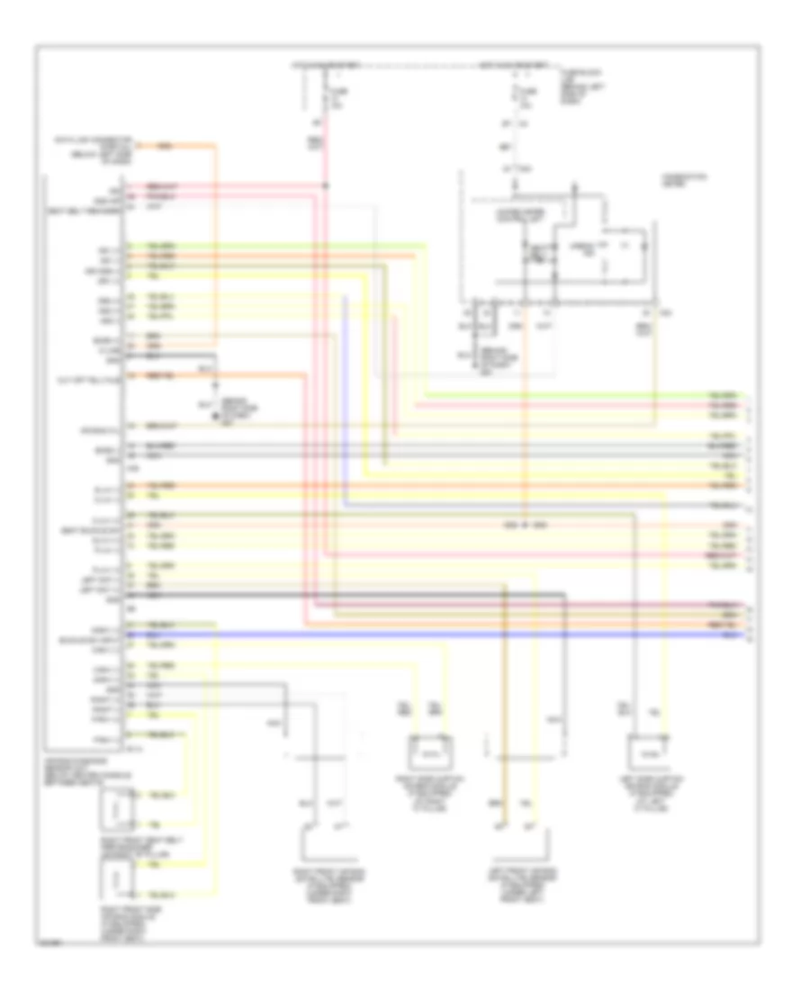
AIR CONDITIONING
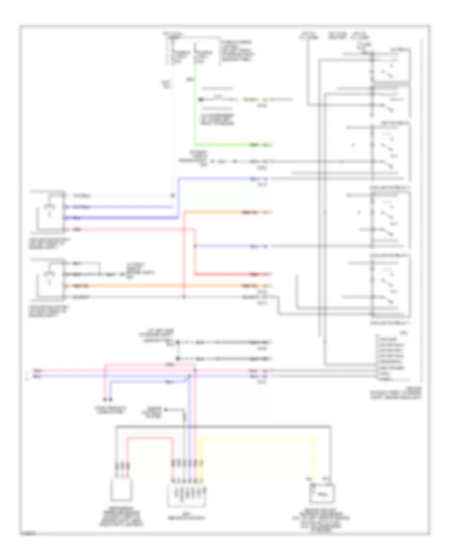
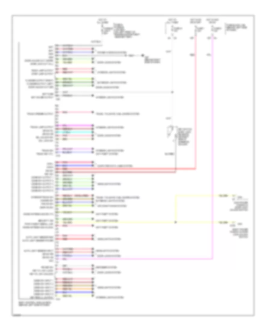
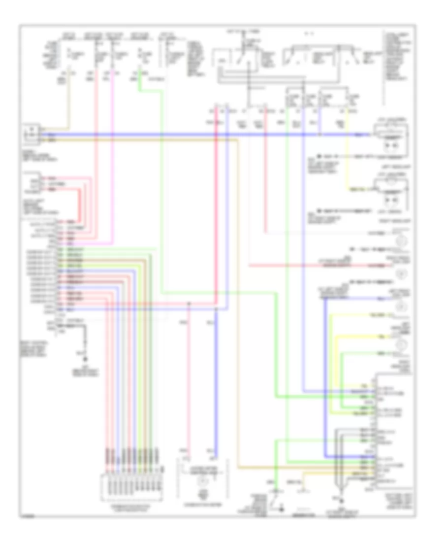
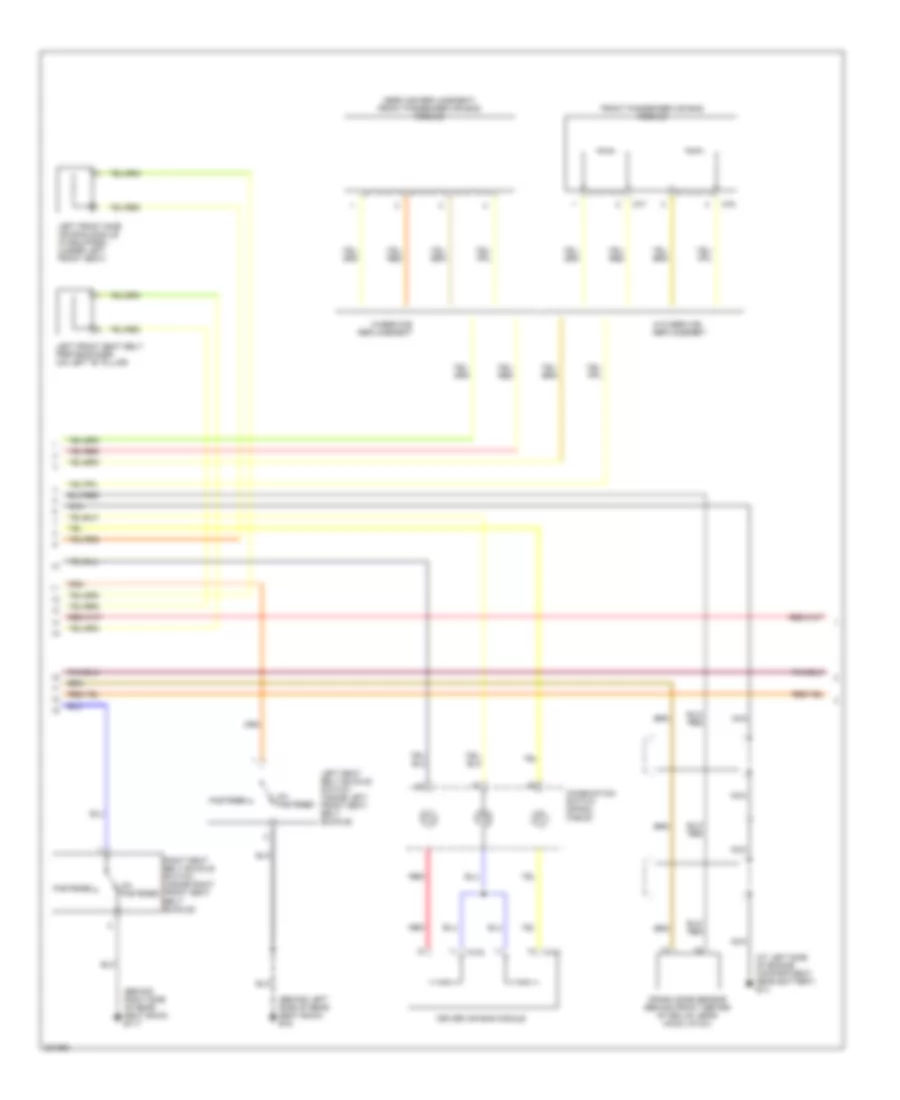
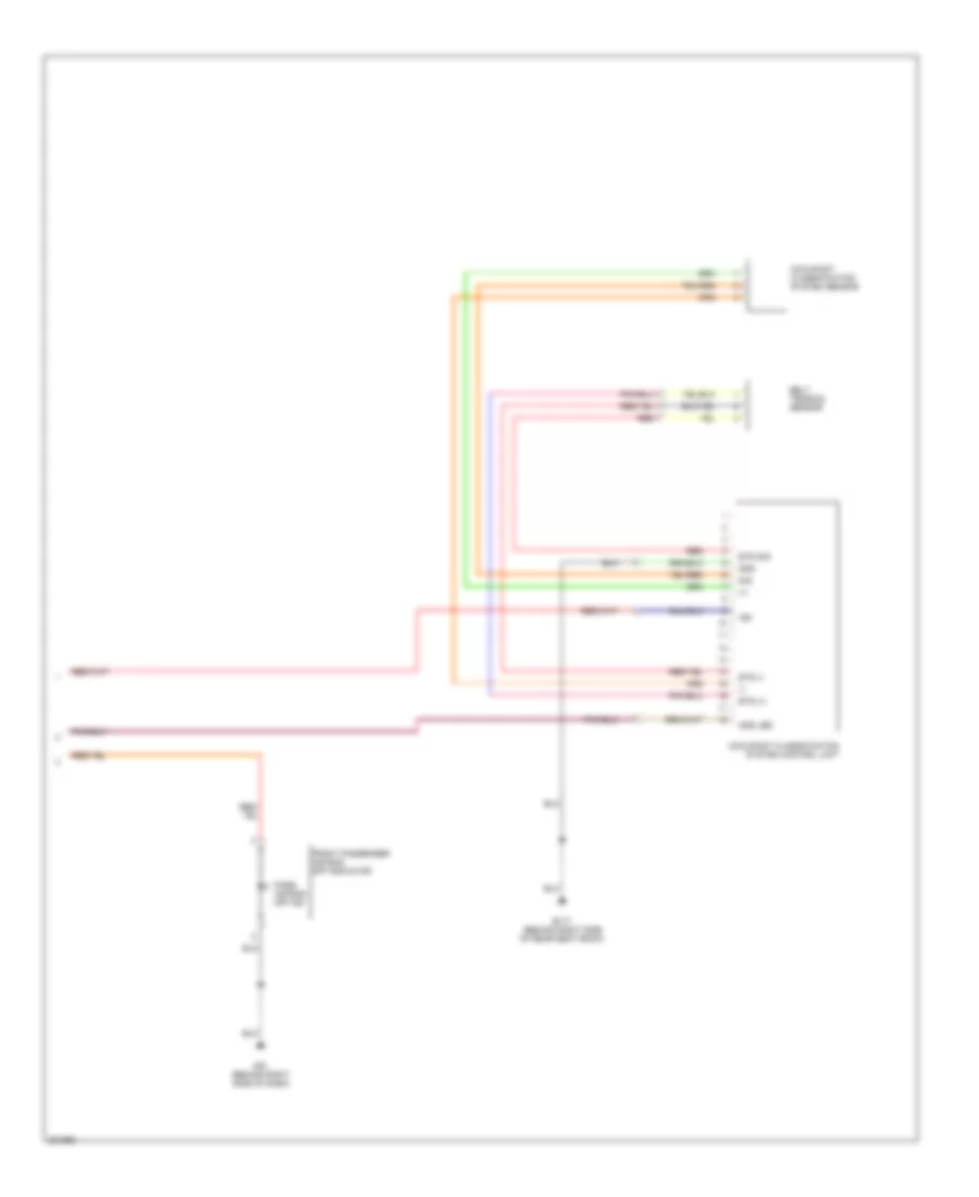
Automatic A/C Wiring Diagram (1 of 2) for Nissan Altima SE 2006
 https://portal-diagnostov.com/license.html
Automotive Electricians Portal FZCO
Automotive Electricians Portal FZCO
https://portal-diagnostov.com/license.html
https://portal-diagnostov.com/license.html
Automotive Electricians Portal FZCO
Automotive Electricians Portal FZCO
List of elements for Automatic A/C Wiring Diagram (1 of 2) for Nissan Altima SE 2006:
- (behind right side of dash) front air control
- (behind right side of dash) m61
- 8n m3
- 8p m4
- A/c pd cut
- Air mix door motor (behind lower left center of dash, on hvac assembly)
- Amb sens
- Ambient sensor (behind lower left side of front grille)
- Bat
- Blower motor (behind lower right side of dash)
- Body control module (bcm) (behind left side of dash)
- Combination meter
- Comp on
- Fan control amplifier (behind lower right side of dash)
- Fan f/b
- Fan gate
- Fan on
- Fuse 10a
- Fuse 15a
- Fuse block (j/b) (behind left side of dash)
- Gnd
- Hot at all times
- Hot in on
- Hot in on or start
- Ign
- Ign 2
- In-vehicle sensor (on left center of dash, near ignition switch)
- Incar sens
- Intake door motor (behind right center of dash, on hvac assembly)
- Intake sens
- Intake sensor (behind right side of dash, on hvac assembly)
- Interior lights system
- Lan sig
- Light+
- Light-
- M49
- M50
- M57 (behind right side of dash)
- Mode door motor (behind left center of dash, on hvac assembly)
- Pnk
- Rr def sw
- Sens gnd
- Sun sens
- Sunload sensor (on upper right side of dash, near base of windshield)
- Unified meter control unit (with odo/trip meter
- Vac
- Vactr
- W/t sens
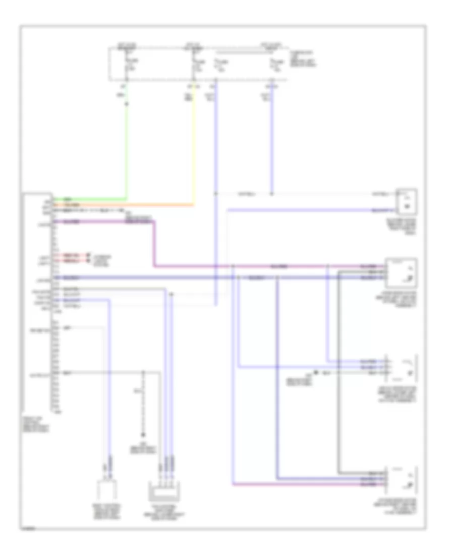
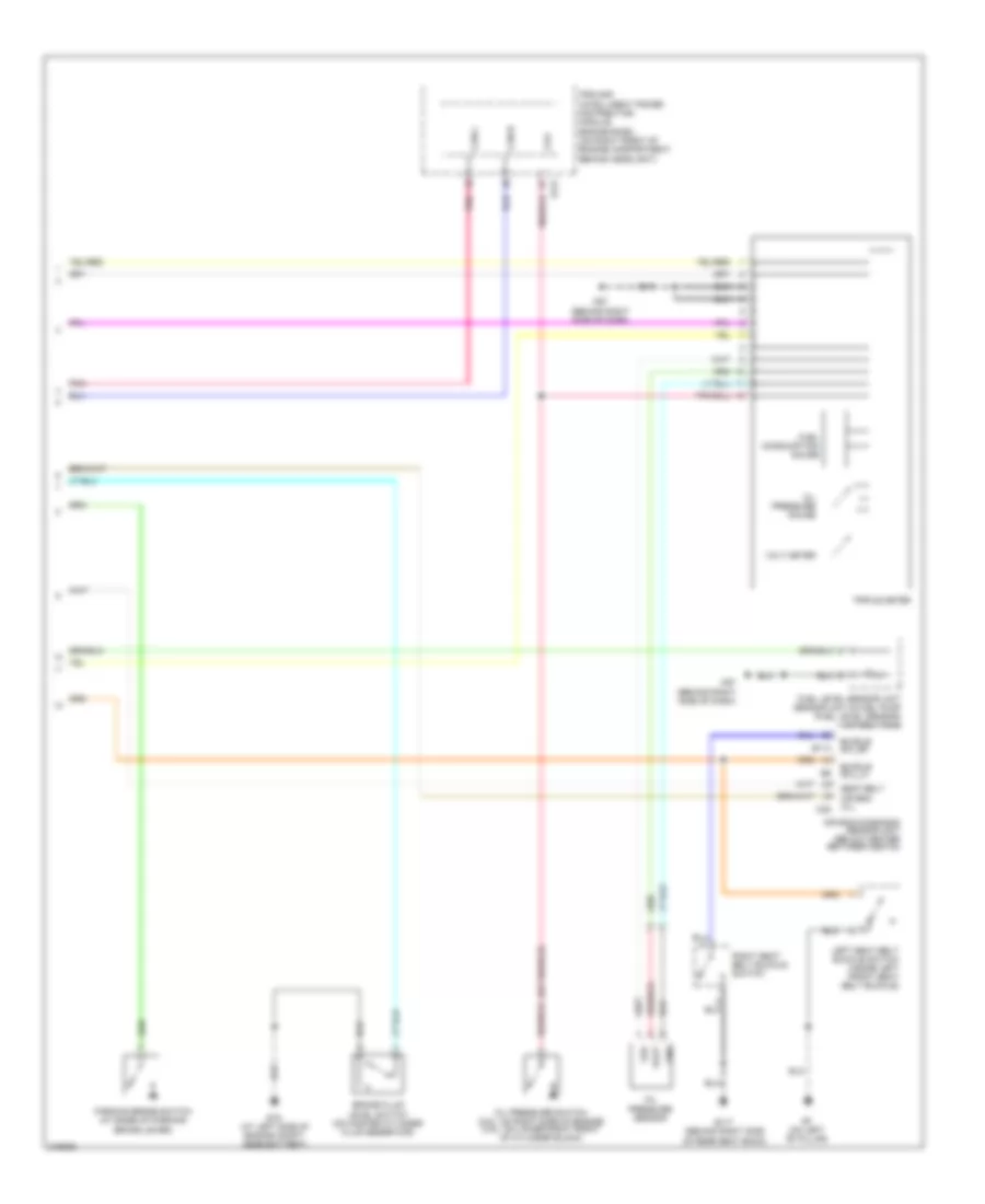
Automatic A/C Wiring Diagram (2 of 2) for Nissan Altima SE 2006
List of elements for Automatic A/C Wiring Diagram (2 of 2) for Nissan Altima SE 2006:
- (at left side of engine compt,
- (at right side of engine compt) e24
- A/c compressor (at lower left front of engine)
- A/c relay
- Air comp
- Avcc
- Can-h
- Can-l
- Computer data lines system
- Cooling fan motor 1 (at right front of engine compt)
- Cooling fan motor 2 (on left front of engine compt)
- Cooling fan relay 1
- Cooling fan relay 2
- Cooling fan relay 3
- Cpu
- E118
- E121
- E123
- E124
- Ecm (behind glove box)
- Engine controls system
- Engine coolant temperature sensor (2.5l: on left rear of engine, on coolant outlet) (3.5l: on upper rear of engine)
- Fuse & fusible link box (on left front of engine compt, near battery)
- Fuse 10a
- Fusible link k 40a
- Fusible link l 40a
- Gnd (power)
- Gnd(signal)
- Gnd-a
- Hot at all times
- Hot in on or start
- Ignition relay
- Ipdm e/r (on right front of engine compt, behind headlight)
- Motor fan-1
- Motor fan-2
- Motor fan-3
- Near battery) e15
- Pdpres
- Pnk
- Red
- Refrigerant pressure sensor (on right front of engine compt, near radiator filler neck)
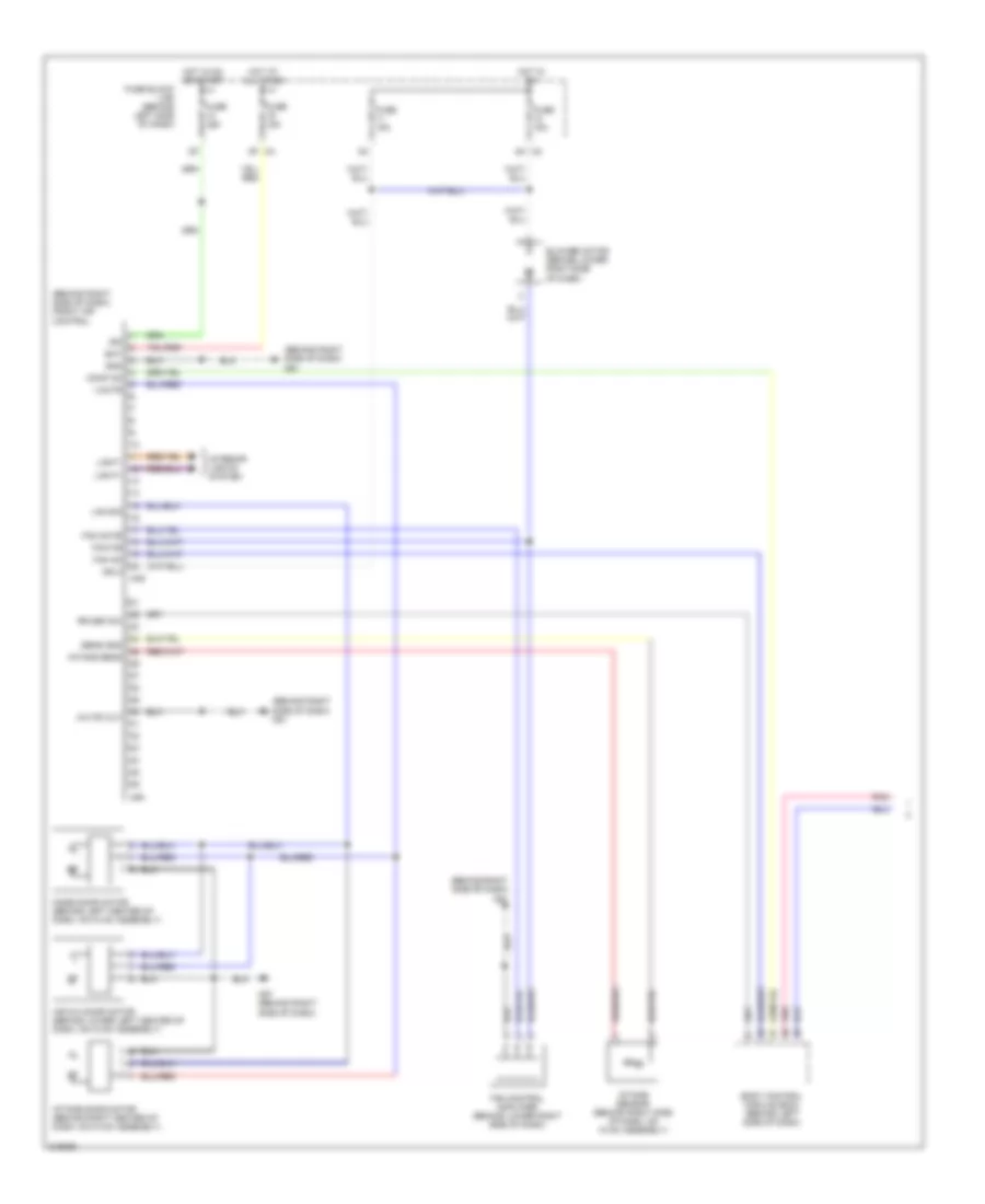
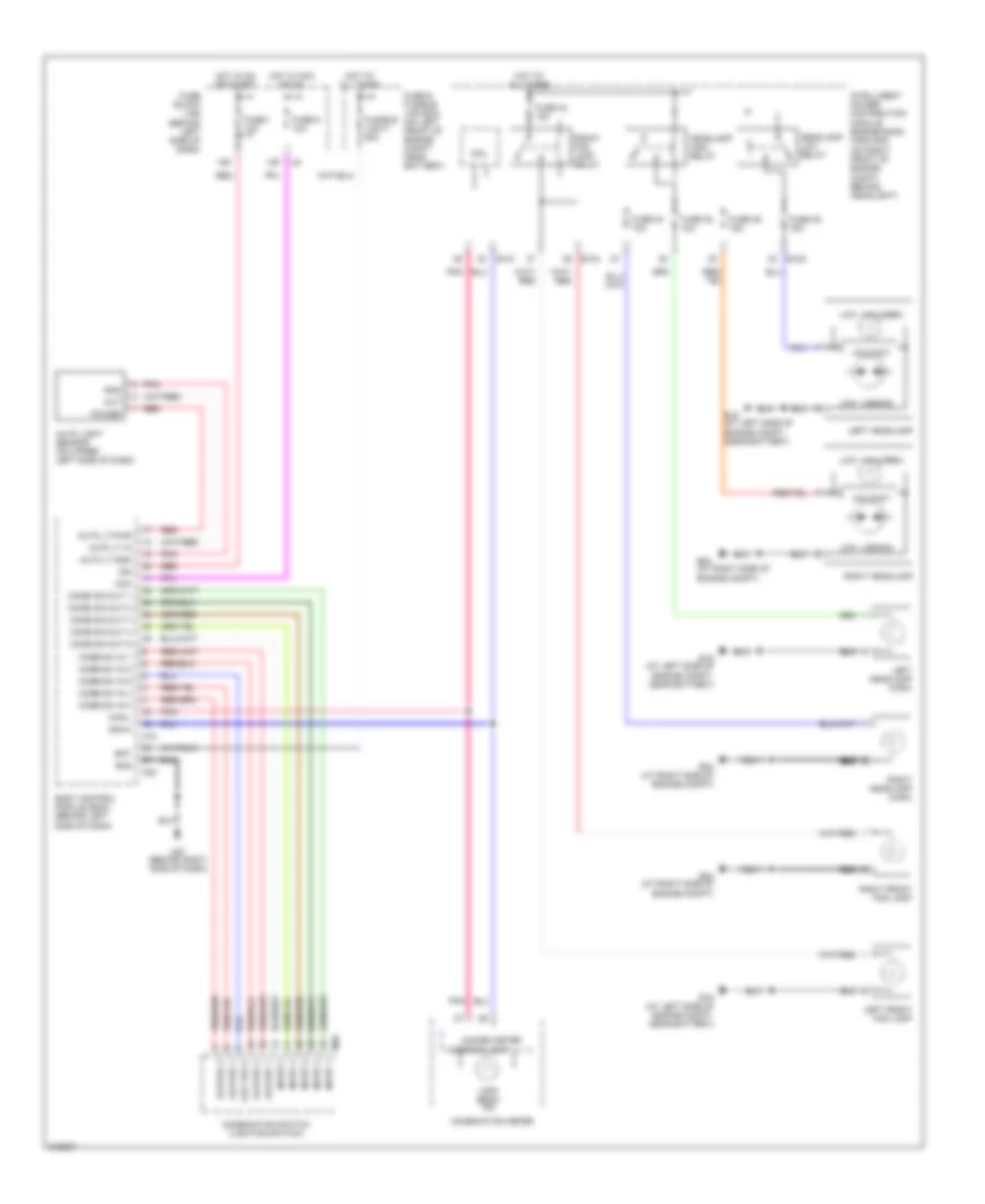
Heater Wiring Diagram for Nissan Altima SE 2006
List of elements for Heater Wiring Diagram for Nissan Altima SE 2006:
- 8n m3
- 8p m4
- A/c pd cut
- Air mix door motor (behind lower left center of dash, on hvac assembly)
- Bat
- Blower motor (behind lower right side of dash)
- Body control module (bcm) (behind left side of dash)
- Comp on
- Fan control amplifier (behind lower right side of dash)
- Fan f/b
- Fan gate
- Front air control (behind right side of dash)
- Fuse 10a
- Fuse 15a
- Fuse block (j/b) (behind left side of dash)
- Gnd
- Hot at all times
- Hot in acc or on
- Hot in on or start
- Ign
- Ign 2
- Intake door motor (behind right center of dash, on hvac assembly)
- Interior lights system
- Lan sig
- Light+
- Light-
- M49
- M50
- M57 (behind right side of dash)
- M61 (behind right side of dash)
- Mode door motor (behind left center of dash, on hvac assembly)
- Rr def sw
- Vactr
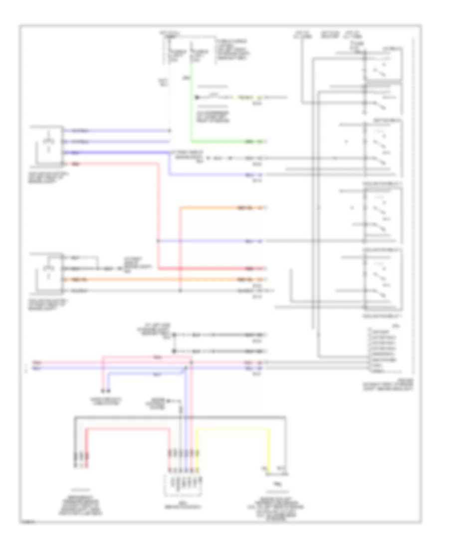
Manual A/C Wiring Diagram (1 of 2) for Nissan Altima SE 2006
List of elements for Manual A/C Wiring Diagram (1 of 2) for Nissan Altima SE 2006:
- (behind right side of dash) front air control
- (behind right side of dash) m61
- 8n m3
- A/c pd cut
- Air mix door motor (behind lower left center of dash, on hvac assembly)
- Bat
- Blower motor (behind lower right side of dash)
- Body control module (bcm) (behind left side of dash)
- Comp on
- Fan control amplifier (behind lower right side of dash)
- Fan f/b
- Fan gate
- Fan on
- Fuse 10a
- Fuse 15a
- Fuse block (j/b) (behind left side of dash)
- Gnd
- Hot at all times
- Hot in on
- Hot in on or start
- Ign
- Ign 2
- Intake door motor (behind right center of dash, on hvac assembly)
- Intake sens
- Intake sensor (behind right side of dash, on hvac assembly)
- Interior lights system
- Lan sig
- Light+
- Light-
- M4 8p
- M49
- M50
- M57 (behind right side of dash)
- Mode door motor (behind left center of dash, on hvac assembly)
- Pnk
- Rr def sw
- Sens gnd
- Vactr
Manual A/C Wiring Diagram (2 of 2) for Nissan Altima SE 2006
List of elements for Manual A/C Wiring Diagram (2 of 2) for Nissan Altima SE 2006:
- (at left side of engine compt, near battery) e15
- (at right side of
- (at right side of engine compt) e24
- A/c compressor (at lower left front of engine)
- A/c relay
- Air comp
- Avcc
- Can-h
- Can-l
- Computer data lines system
- Cooling fan motor 1 (at right front of engine compt)
- Cooling fan motor 2 (on left front of engine compt)
- Cooling fan relay 1
- Cooling fan relay 2
- Cooling fan relay 3
- Cpu
- E118
- E121
- E123
- E124
- Ecm (behind glove box)
- Engine compt) e24
- Engine controls system
- Engine coolant temperature sensor (2.5l: on left rear of engine, on coolant outlet) (3.5l: on upper rear of engine)
- Fuse & fusible link box (on left front of engine compt, near battery)
- Fuse 10a
- Fusible link k 40a
- Fusible link l 40a
- Gnd (power)
- Gnd(signal)
- Gnd-a
- Hot at all times
- Hot in on or start
- Ignition relay
- Ipdm e/r (on right front of engine compt, behind headlight)
- Motor fan-1
- Motor fan-2
- Motor fan-3
- Pdpres
- Pnk
- Red
- Refrigerant pressure sensor (on right front of engine compt, near radiator filler neck)
ANTI-LOCK BRAKES
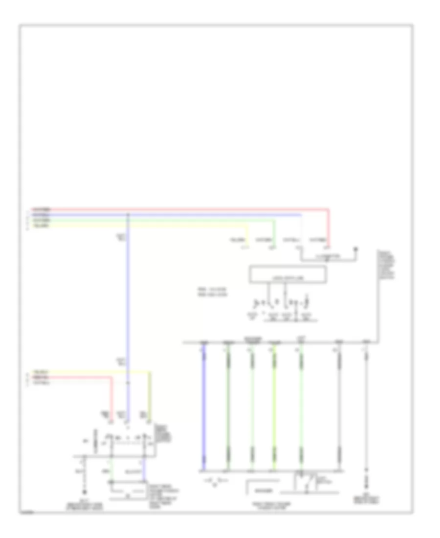
Anti-lock Brakes Wiring Diagram, with Traction Control for Nissan Altima SE 2006
List of elements for Anti-lock Brakes Wiring Diagram, with Traction Control for Nissan Altima SE 2006:
- (below left side of dash) data link connector
- Abs actuator & electric unit (control unit) (on lower right rear of engine compt)
- Abs fail lamp
- Abs warning ind
- Abs/tcs control unit
- Actuator
- Can-h
- Can-l
- Combination meter
- Computer data lines system
- Diag l
- Dp fl
- Dp fr
- Dp rl
- Dp rr
- Ds fl
- Ds fr
- Ds rl
- Ds rr
- E124
- E126 (near abs actuator)
- E30
- Fl in
- Fl out
- Fr in
- Fr out
- Fuse & fusible link box (on left front of engine compt, near battery)
- Fuse 10a
- Fuse block (j/b) (behind left side of dash)
- Fusible link g 30a
- Fusible link h 30a
- Gnd
- Hot at all times
- Hot in on or start
- Ign
- Illum
- Intelligent power distribution module engine room (ipdm e/r) (on right front of engine compt, behind headlight)
- Interior lights system
- K-line
- Left front wheel sensor (at left front wheel hub assembly)
- Left rear wheel sensor (on left rear wheel hub assembly)
- M24
- M57 (behind right side of dash)
- Motor monitor
- Motor relay
- Motor relay actuator
- Nca
- Pnk
- Red
- Relay unit
- Right front wheel sensor (at right front wheel hub assembly)
- Right rear wheel sensor (on right rear wheel hub assembly)
- Rl in
- Rl out
- Rr in
- Rr out
- Slip ind
- Sol valve relay actuator
- Solenoid valve relay
- Stop
- Stop lamp switch (above brake pedal, on bracket)
- Tcs off ind
- Tcs on/off switch
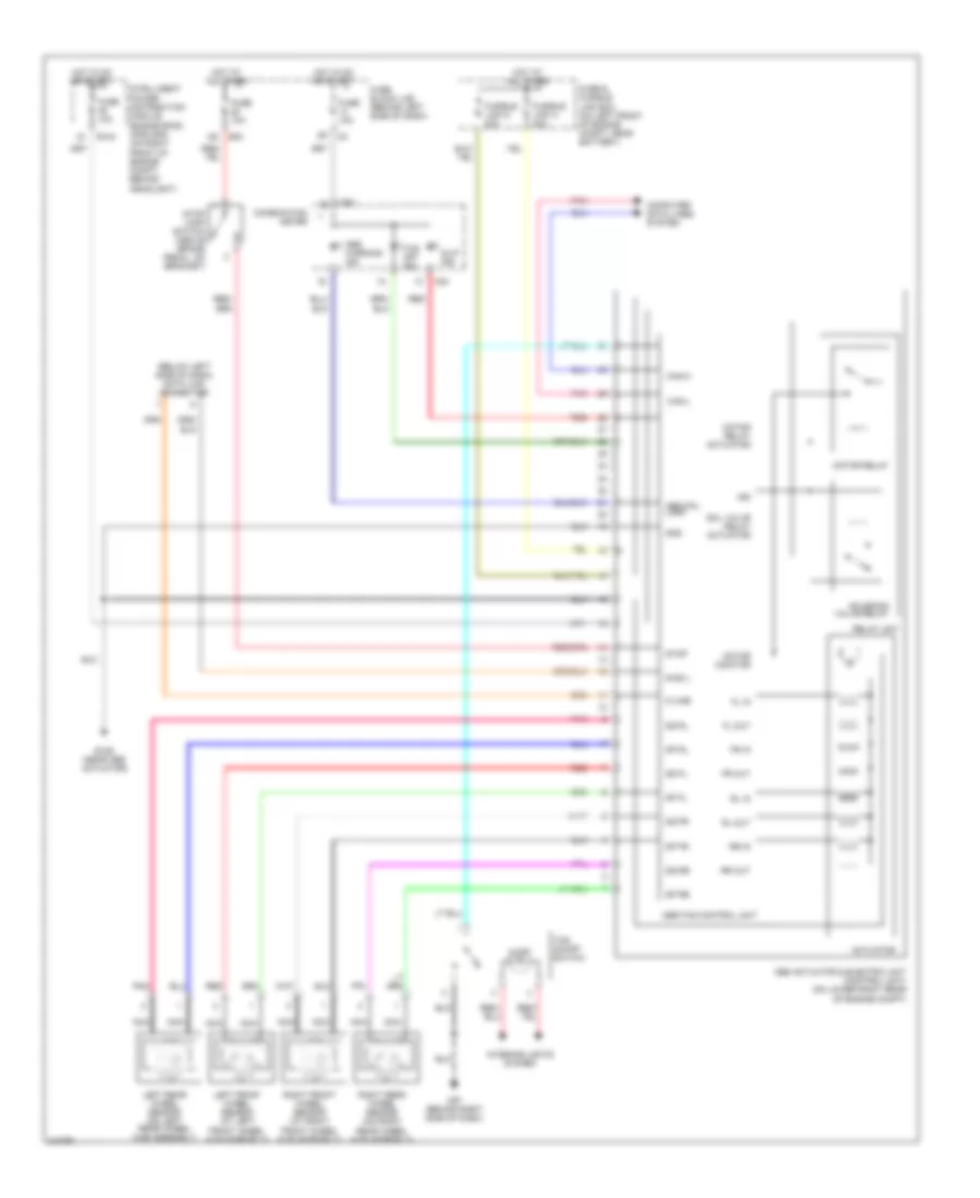
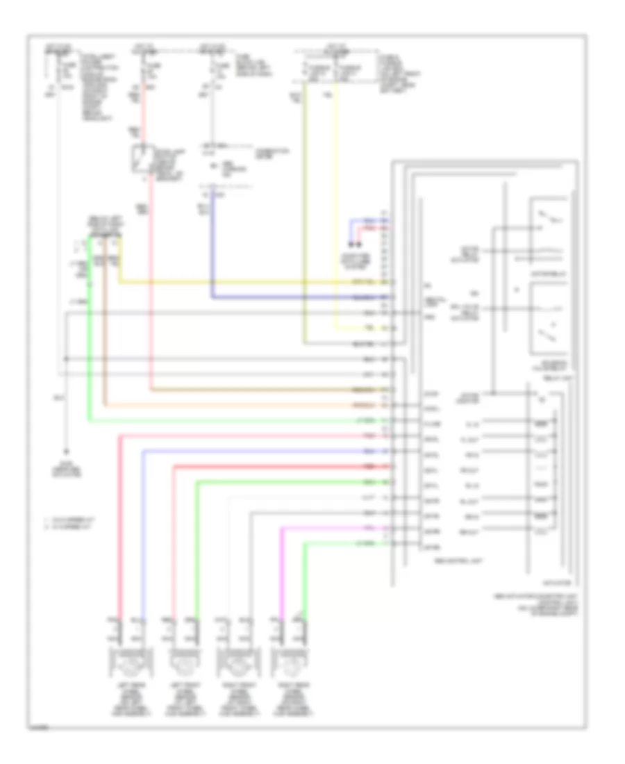
Anti-lock Brakes Wiring Diagram, without Traction Control for Nissan Altima SE 2006
List of elements for Anti-lock Brakes Wiring Diagram, without Traction Control for Nissan Altima SE 2006:
- (below left side of dash) data link connector
- Abs actuator & electric unit (control unit) (on lower right rear of engine compt)
- Abs control unit
- Abs fail lamp
- Abs warning ind
- Actuator
- Combination meter
- Computer data lines system
- Diag l
- Dp fl
- Dp fr
- Dp rl
- Dp rr
- Ds fl
- Ds fr
- Ds rl
- Ds rr
- E124
- E126 (near abs actuator)
- E30
- Fl in
- Fl out
- Fr in
- Fr out
- Fuse & fusible link box (on left front of engine compt, near battery)
- Fuse 10a
- Fuse block (j/b) (behind left side of dash)
- Fusible link g 30a
- Fusible link h 30a
- Gnd
- Hot at all times
- Hot in on or start
- Ign
- Intelligent power distribution module engine room (ipdm e/r) (on right front of engine compt, behind headlight)
- K-line
- Left front wheel sensor (at left front wheel hub assembly)
- Left rear wheel sensor (on left rear wheel hub assembly)
- M24
- Motor monitor
- Motor relay
- Motor relay actuator
- Nca
- Pnk
- Red
- Relay unit
- Right front wheel sensor (at right front wheel hub assembly)
- Right rear wheel sensor (on right rear wheel hub assembly)
- Rl in
- Rl out
- Rr in
- Rr out
- Sol valve relay actuator
- Solenoid valve relay
- Stop
- Stop lamp switch (above brake pedal, on bracket)
- W/ 5 speed a/t
- W/o 5 speed a/t
ANTI-THEFT
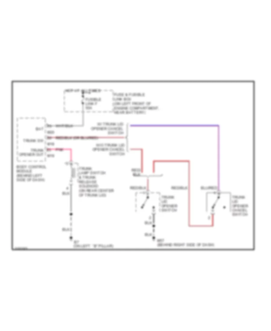
Forced Entry Wiring Diagram for Nissan Altima SE 2006
List of elements for Forced Entry Wiring Diagram for Nissan Altima SE 2006:
- (at right front door sill)
- (on right front of engine compt, behind headlight) ipdm e/r
- 12p
- Acc
- B7 (on left "b" pillar)
- Bat
- Bat fuse
- Body control module (bcm) (behind left side of dash)
- Can h
- Can l
- Can-h
- Can-l
- Com
- Cpu
- D105
- D106
- Data link connector (below left side of dash)
- Door lock & unlock switch
- Dr sw as
- Dr sw dr
- Dr sw rl
- Dr sw rr
- E121
- E122
- Exterior lights system
- Fuse & fusible link box (on left front of engine compt, near battery)
- Fuse 10a
- Fuse block (j/b) (behind left side of dash)
- Fusible link f 50a
- Gnd
- Headlamp high relay
- Headlights system
- Horn relay
- Horns system
- Hot at all times
- Hot in acc or on
- Key sw
- Key switch & key lock solenoid (on right side of steering column)
- Left front door lock assembly (key cylinder switch)
- Left front door switch
- Left front door switch (at left front door sill)
- Left rear door switch (at left rear door sill)
- Lk sw
- Lock-between full stroke & normal unlock-between full stroke & normal
- M18
- M19
- M20
- M57 (behind right side of dash)
- M61 (behind right side of dash)
- Main power window & door lock/ unlock switch
- Pnk
- Pwr win ser link
- Right power window & door lock/ unlock switch
- Right rear door switch (at right rear door sill)
- Sec ind out
- Security indicator lamp
- Tail lamp relay
- Trunk key cylinder switch (unlock switch)
- Trunk key cyl
- Trunk lamp switch & trunk release solenoid (on rear center of trunk lid)
- Trunk sw
- Unlk
- Unlk sw
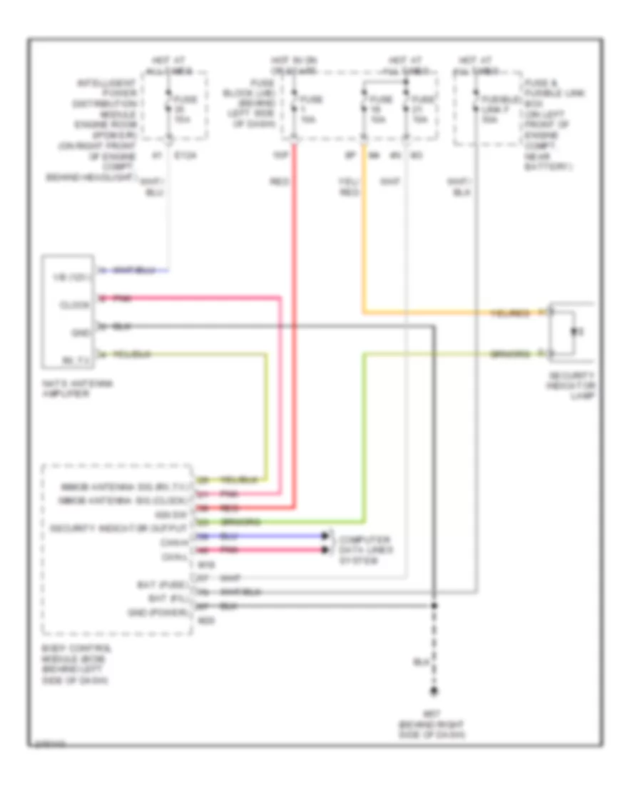
Immobilizer Wiring Diagram for Nissan Altima SE 2006
List of elements for Immobilizer Wiring Diagram for Nissan Altima SE 2006:
- 15p
- 4n m3
- Bat (f/l)
- Bat (fuse)
- Body control module (bcm) (behind left side of dash)
- Can-h
- Can-l
- Clock
- Computer data lines system
- E124
- Fuse & fusible link box (on left front of engine compt, near battery)
- Fuse 10a
- Fuse 15a
- Fuse block (j/b) (behind left side of dash)
- Fusible link f 50a
- Gnd
- Gnd (power)
- Hot at all times
- Hot in on or start
- Ign sw
- Immob antenna sig (clock)
- Immob antenna sig (rx,tx)
- Intelligent power distribution module engine room (ipdm e/r) (on right front of engine compt, behind headlight)
- M18
- M20
- M57 (behind right side of dash)
- Nats antenna amplifier
- Pnk
- Red
- Rx,tx
- Security indicator lamp
- Security indicator output
- Vb (12v)
BODY CONTROL MODULES
Body Control Modules Wiring Diagram for Nissan Altima SE 2006
List of elements for Body Control Modules Wiring Diagram for Nissan Altima SE 2006:
- 12p
- 15p
- Acc
- Air conditioning system
- Anti-theft system
- Auto light sensor gnd
- Auto light sensor input
- Auto light sensor power
- Bat
- Bat fuse
- Bat saver output
- Body control module (bcm) (behind left side of dash)
- Can-h
- Can-l
- Cdl lock sw
- Cdl unlock sw
- Com
- Combi sw input 1
- Combi sw input 2
- Combi sw input 3
- Combi sw input 4
- Combi sw input 5
- Combi sw output 1
- Combi sw output 2
- Combi sw output 3
- Combi sw output 4
- Combi sw output 5
- Comp on sw
- Computer data lines system
- D105
- Defogger system
- Door lock out (all)
- Door locks system
- Door unlock out (as/rr)
- Door unlock out (dr)
- Dr sw as
- Dr sw dr
- Dr sw rl
- Dr sw rr
- Exterior lights system
- Fan on sw
- Flasher output (left)
- Flasher output (right)
- Fuse & fusible link box (on left front of engine compartment, near battery)
- Fuse 1 10a
- Fuse 21 10a
- Fuse 6 10a
- Fuse block (j/b) (behind left side of dash)
- Fusible link f 50a
- Gnd
- Hazard sw
- Headlights system
- Hot at all times
- Hot in acc or on
- Hot in on or start
- Ign sw
- Immob antenna sig (clock)
- Immob antenna sig (rx,tx)
- Interior lights system
- Interior trunk sw
- Key cyl sw (lock)
- Key cyl sw (unlock)
- Key ring ill output
- Key sw
- Key switch & key lock solenoid (on right side of steering column)
- M18
- M19
- M20
- M57 (behind right side of dash)
- Main power window & door lock/ unlock switch
- Pnk
- Power windows system
- Pwr window serial link
- Rap
- Red
- Right power window & door lock/unlock switch
- Room lamp output
- Rr def sw
- Security ind
- Step lamp output
- Trunk key cyl
- Trunk lamp output
- Trunk opener output
- Trunk sw
- Trunk, tailgate, fuel doors system
COMPUTER DATA LINES
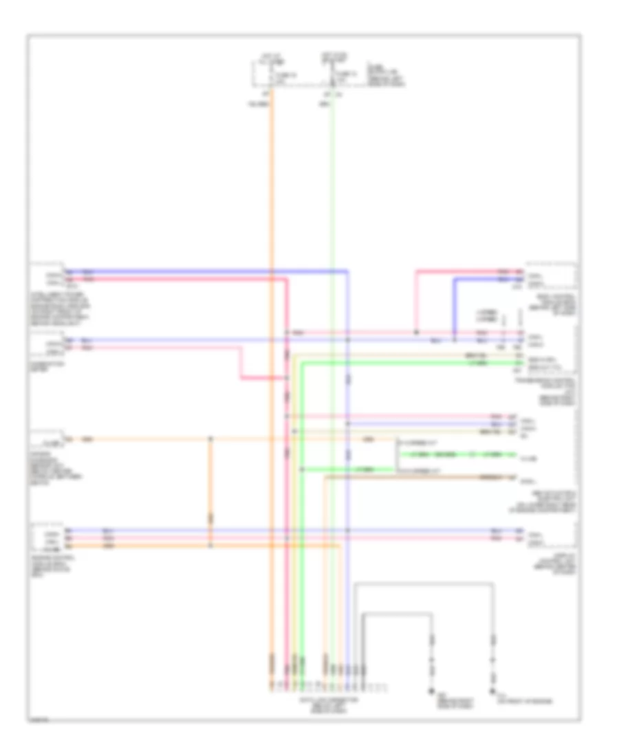
Computer Data Lines Wiring Diagram for Nissan Altima SE 2006
List of elements for Computer Data Lines Wiring Diagram for Nissan Altima SE 2006:
- (behind left side of dash)
- 4 speed
- 5 speed
- Abs actuator & electric unit (on lower right rear of engine compartment)
- Air bag diagnosis sensor unit (below center console, between seats)
- Body control module (bcm) (behind left side of dash)
- Can-h
- Can-l
- Combination meter
- Data link connector (below left side of dash)
- Diag l
- Display control unit (behind center of dash)
- E121
- Engine control module (ecm) (behind glove box)
- F14 (on front of engine)
- F56
- F57
- Fuse 12 10a
- Fuse 19 10a
- Fuse block (j/b)
- Hot at all times
- Hot in on or start
- Intelligent power distribution module engine room (ipdm e/r) (on right front of engine compartment, behind headlight)
- K-line
- M18
- M57 (behind right side of dash)
- Pnk
- Sss in (rx)
- Sss out (tx)
- Transmission control module (tcm) (a/t) (behind right side of dash)
- W/ 5 speed a/t
- W/o 5 speed a/t
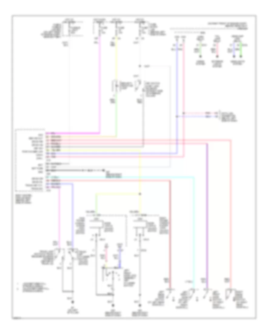
COOLING FAN
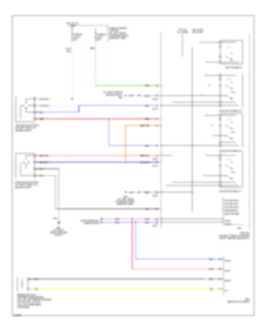
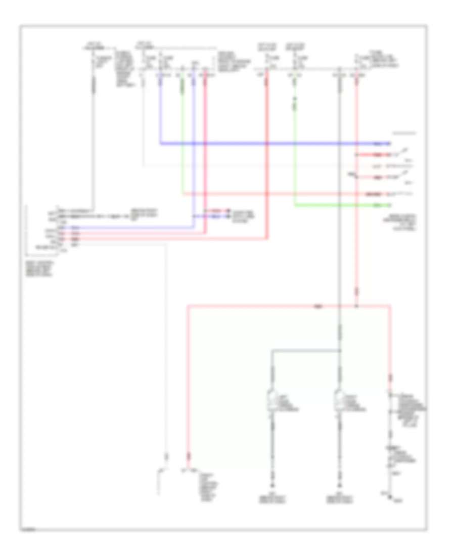
Cooling Fan Wiring Diagram for Nissan Altima SE 2006
List of elements for Cooling Fan Wiring Diagram for Nissan Altima SE 2006:
- (at right side of engine compt) e24
- Can-h
- Can-l
- Computer data lines system
- Cooling fan motor 1 (at right front of engine compt)
- Cooling fan motor 2 (on left front of engine compt)
- Cooling fan relay 1
- Cooling fan relay 2
- Cooling fan relay 3
- Cpu
- E118
- E121
- E123
- E124
- E15 (at left side of engine compt, near battery)
- E24 (at right side of engine compt)
- Ecm (behind glove box)
- Engine coolant temperature sensor (2.5l: on left rear of engine, on coolant outlet) (3.5l: on upper rear of engine)
- Fuse & fusible link box (on left front of engine compt, near battery)
- Fusible link k 40a
- Fusible link l 40a
- Gnd (power)
- Gnd(signal)
- Gnd-a
- Hot at all times
- Hot in on or start
- Ignition relay
- Ipdm e/r (on right front of engine compt, behind headlight)
- Motor fan-1
- Motor fan-2
- Motor fan-3
- Pnk
- Red
CRUISE CONTROL
Cruise Control Wiring Diagram for Nissan Altima SE 2006
List of elements for Cruise Control Wiring Diagram for Nissan Altima SE 2006:
- A/t
- Ascd brake switch (above brake pedal, on bracket)
- Ascd clutch switch (above clutch pedal, on bracket)
- Ascd steering switch
- Ascd sw
- Avcc2
- Bnc sw
- Brake sw
- Can-h
- Can-l
- Cancel switch
- Close
- Combination meter
- Combination switch (spiral cable)
- Computer data lines system
- Cruise ind
- Cruise switch
- E30
- Electric throttle control actuator (integral with throttle body, on intake manifold)
- Engine control module (ecm) (behind glove box)
- F14 (on front of engine)
- Fuse 12 10a
- Fuse 14 10a
- Fuse 20 10a
- Fuse block (j/b) (behind left side of dash)
- Gnd-a
- Hot at all all times
- Hot in on or start
- M/t
- M102
- M24
- M30
- M57 (behind right side of dash)
- Motor 1
- Motor 2
- Open
- Pnk
- Red
- Resume/accel switch
- Sensor 1
- Sensor 2
- Set ind
- Set/coast switch
- Stop lamp switch (above brake pedal, on bracket)
- Tps1
- Tps2
- Unified meter control unit
- Vehicle speed sensor (on right front of transaxle, near right axle flange)
DEFOGGERS
Defoggers Wiring Diagram for Nissan Altima SE 2006
List of elements for Defoggers Wiring Diagram for Nissan Altima SE 2006:
- (behind right side of dash) m57
- + b301
- - b201
- 15p
- 2p m4
- B202
- Bat
- Body control module (bcm) (behind left side of dash)
- Can-h
- Can-l
- Computer data lines
- Cpu
- E119
- E121
- E30
- Front air control (behind right side of dash)
- Fuse & fusible link box (on left front of engine compt, near battery)
- Fuse 10a
- Fuse 20a
- Fuse block (j/b) (behind left
- Fusible link f 50a
- Gnd
- Hot at all times
- Hot in on or start
- Ign
- Ipdm e/r (on right front of engine compt, behind headlight)
- Left door mirror (in mirror)
- M18
- M20
- M50
- M57 (behind right side of dash)
- M61 (behind right side of dash)
- Pnk
- Rear window defogger
- Rear window defogger condenser (near base of left "c" pillar)
- Rear window defogger relay (at left kick panel)
- Red
- Right door mirror (in mirror)
- Rr def sw
- Side of dash)
- System
ENGINE PERFORMANCE
2.5L
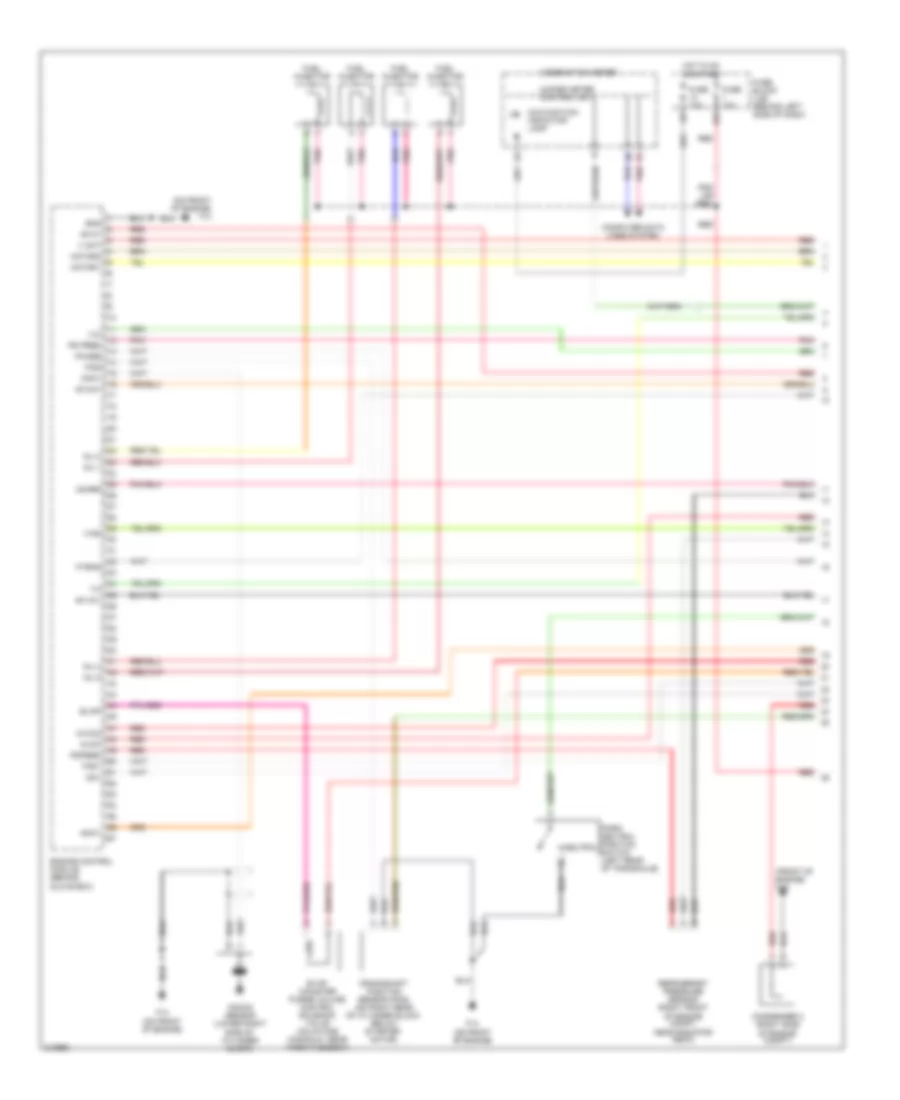
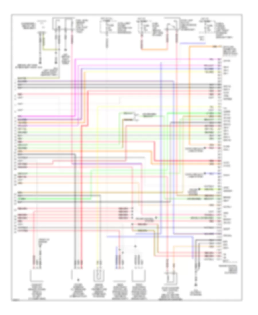
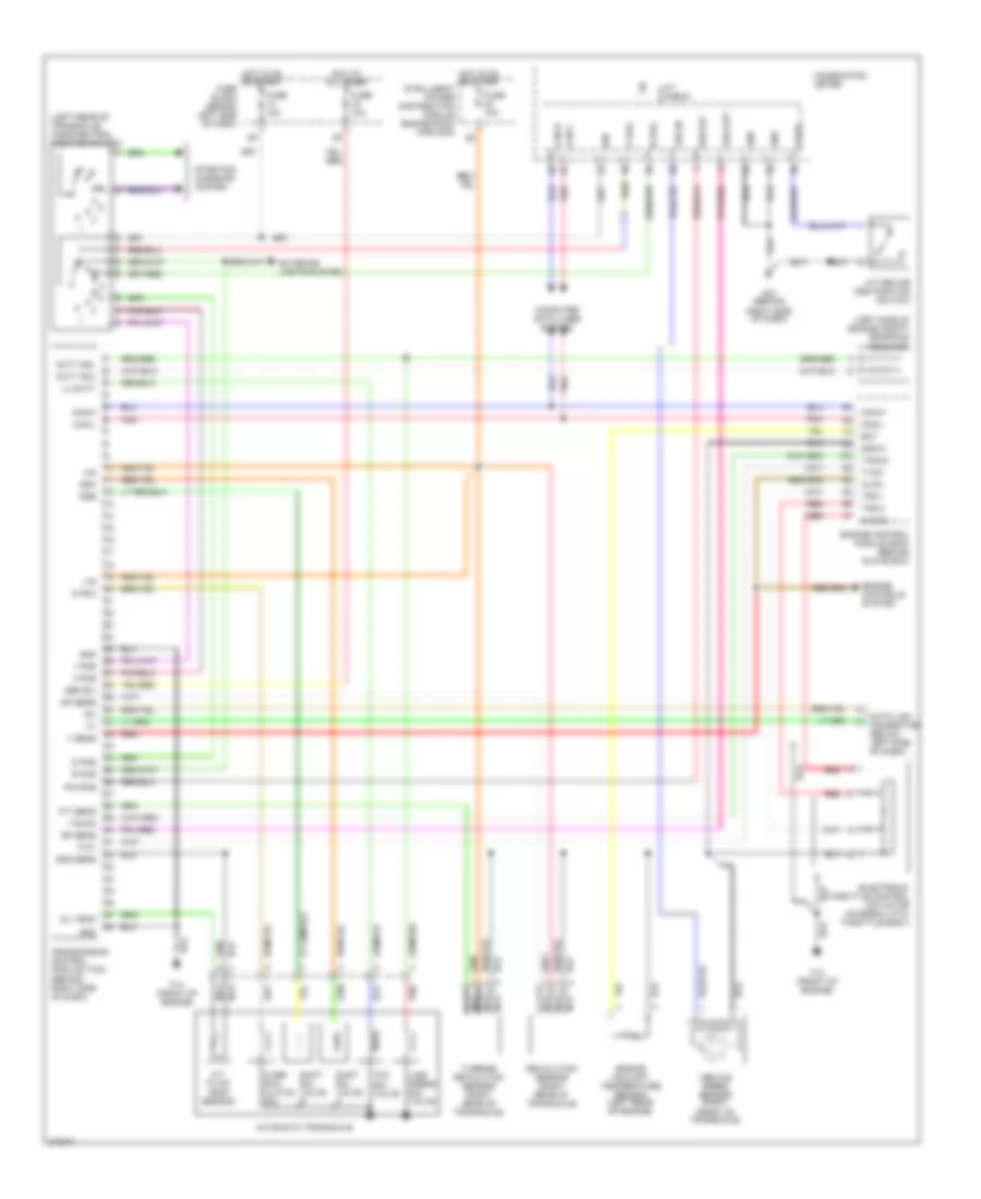
2.5L, Engine Performance Wiring Diagram (1 of 4) for Nissan Altima SE 2006
List of elements for 2.5L, Engine Performance Wiring Diagram (1 of 4) for Nissan Altima SE 2006:
- (front of engine) f16
- (on front of engine) f14
- 15p
- Af-h1
- Af-un1
- Af-vm1
- Afip1
- Avcc
- Avcc2
- Combination meter
- Computer data lines system
- Condenser 2 (right side of engine compt)
- Crankshaft position sensor (pos) (on right rear of cylinder block, below starter motor)
- Engine control module (behind glove box)
- Evap
- Evap canister purge volume control solenoid valve (on intake manifold, near throttle body)
- F14 (on front of engine)
- Ftrps
- Fuel injector
- Fuse 10a
- Fuse block (j/b) (behind left side of dash)
- Gnd
- Hot in on or start
- Inj 1
- Inj 2
- Inj 3
- Inj 4
- Ivc
- Knk1
- Knock sensor (lower right side of cylinder block)
- Malfunction indicator lamp
- Motor1
- Motor2
- Neutral
- O2hrr
- Park/ neutral position switch (left rear of transaxle)
- Pdpres
- Phase
- Pnk
- Pnk (or red)
- Pos
- Ps pres
- Qa+
- Red
- Refrigerant pressure sensor (right front of engine compt, near radiator neck)
- Tps1
- Unified meter control unit
- V mot
- Vias
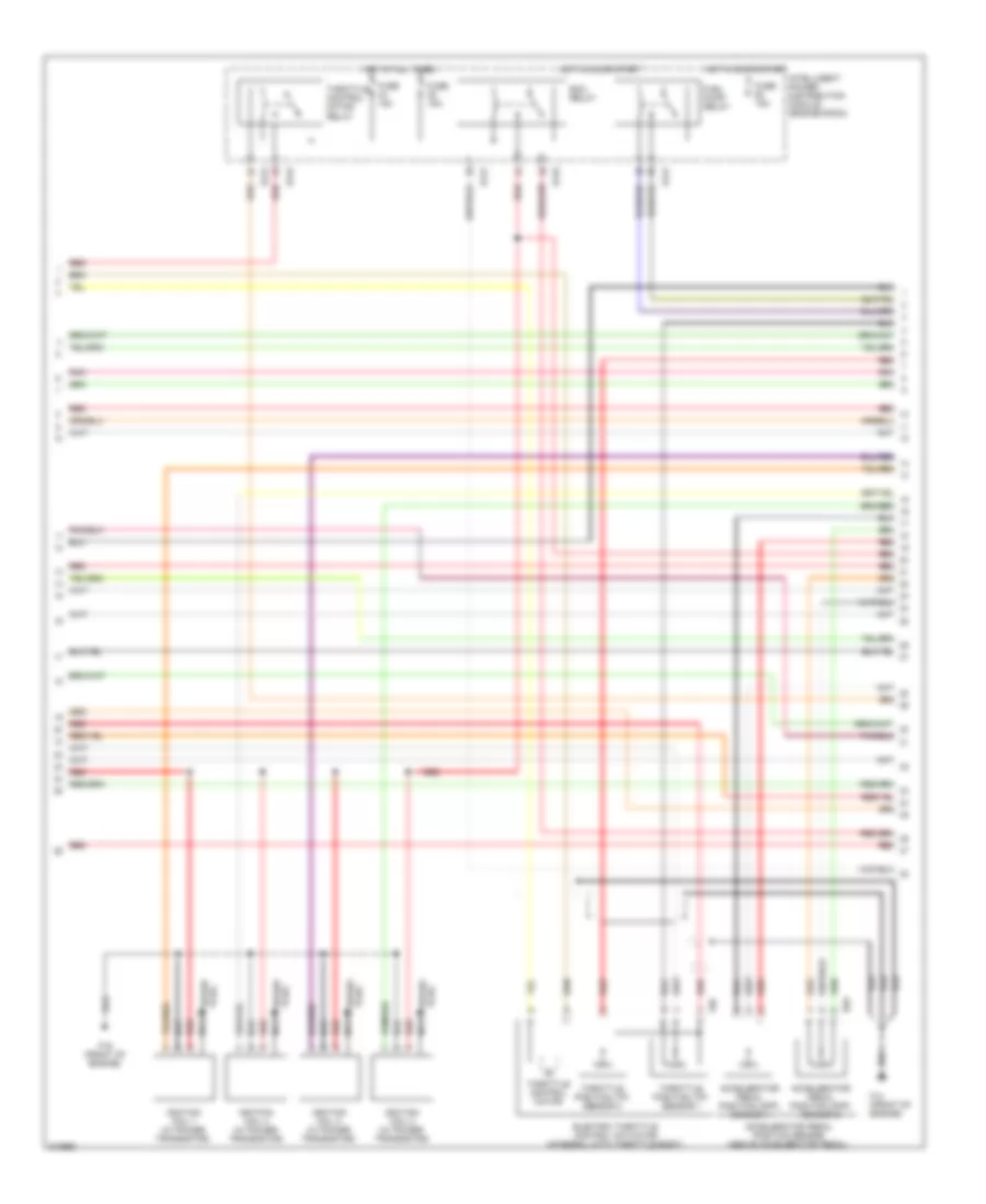
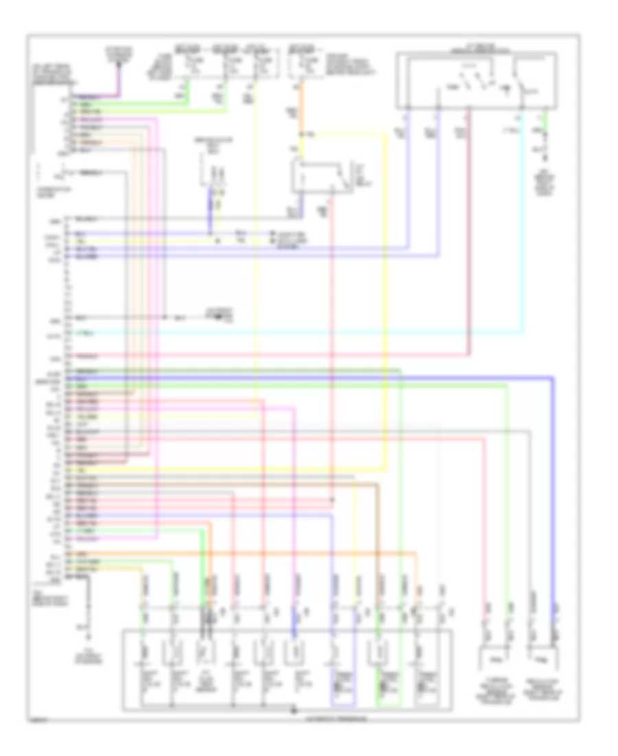
2.5L, Engine Performance Wiring Diagram (2 of 4) for Nissan Altima SE 2006
List of elements for 2.5L, Engine Performance Wiring Diagram (2 of 4) for Nissan Altima SE 2006:
- Accelerator pedal position (app) sensor 1
- Accelerator pedal position (app) sensor 2
- Accelerator pedal position sensor (above accelerator pedal)
- E121
- E122
- E124
- E40
- Ecm relay
- Electric throttle control actuator (integral with throttle body)
- F14 (front of engine)
- F16 (front of engine)
- F50
- Fuel pump relay
- Fuse 15a
- Hot at all times
- Hot in on or start
- Ignition coil 1 (w/ power transistor)
- Ignition coil 2 (w/ power transistor)
- Ignition coil 3 (w/ power transistor)
- Ignition coil 4 (w/ power transistor)
- Intelligent power distribution module (engine room)
- Nca
- Plug spark
- Pnk
- Red
- Spark plug
- Throttle control motor
- Throttle control motor relay
- Throttle position (tp) sensor 1
- Throttle position (tp) sensor 2
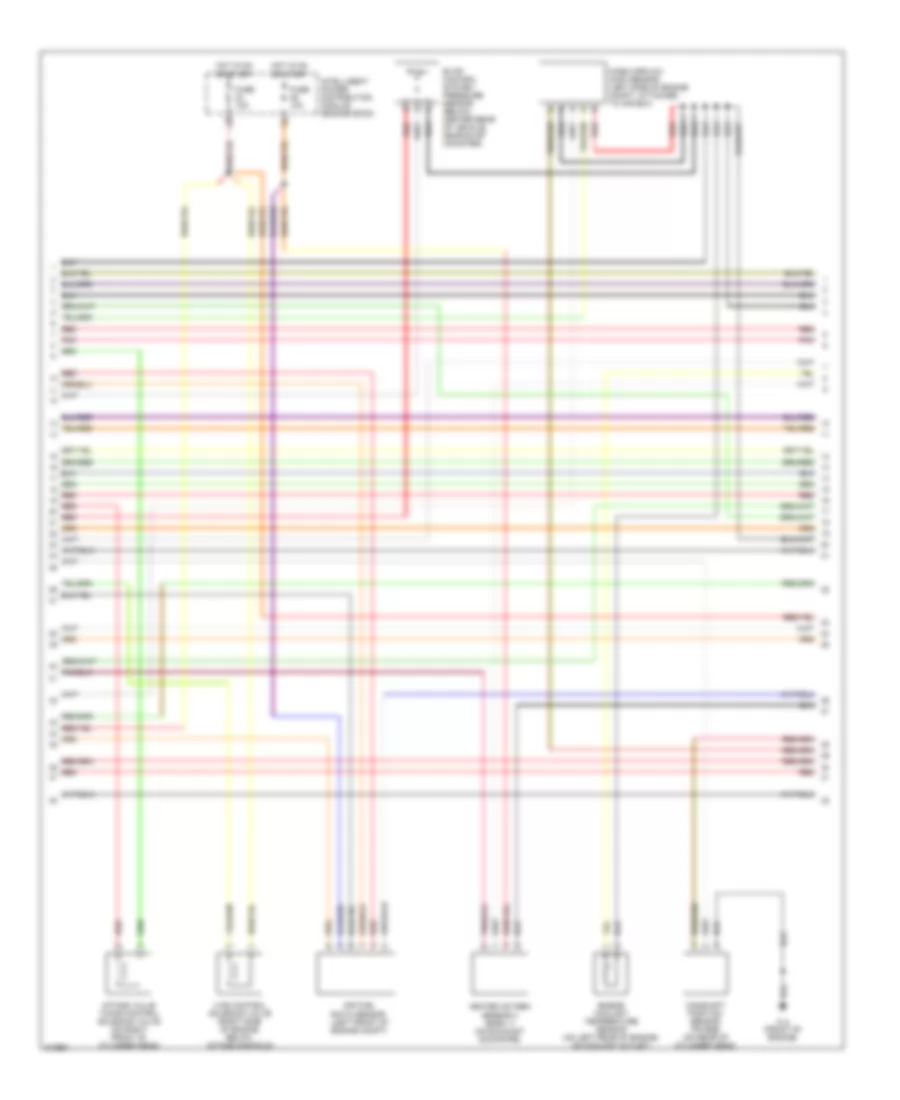
2.5L, Engine Performance Wiring Diagram (3 of 4) for Nissan Altima SE 2006
List of elements for 2.5L, Engine Performance Wiring Diagram (3 of 4) for Nissan Altima SE 2006:
- Air fuel ratio sensor (left front of engine compt)
- Camshaft position sensor (phase) (on rear of cylinder head)
- Engine coolant temperature sensor (on left rear of engine, on coolant outlet)
- Evap control system pressure sensor (below center rear of vehicle, near evap canister)
- F14 (front of engine)
- Fuse 10a
- Heated oxygen sensor 2 (bank 1) (on exhaust downpipe)
- Hot in on or start
- Intake valve timing control solenoid valve (on right front of cylinder head)
- Intelligent power distribution module (engine room)
- Mass airflow (maf) sensor (left side of engine compt, attached to air box)
- Pnk
- Red
- Vias control solenoid valve (right side of engine, below intake manifold)
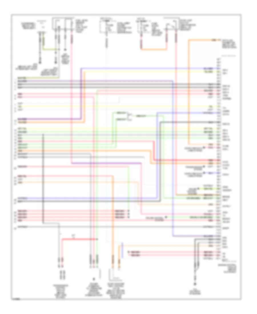
2.5L, Engine Performance Wiring Diagram (4 of 4) for Nissan Altima SE 2006
List of elements for 2.5L, Engine Performance Wiring Diagram (4 of 4) for Nissan Altima SE 2006:
- A/f-ia1
- A/t
- Aps1
- Aps2
- Ascdsw
- Avcc
- Avcc2
- B19 (behind left side of rear seat back)
- Batt
- Bncsw
- Brake
- Can l
- Can-h
- Cdcv
- Computer data lines system
- Condenser 1 (below left rear seat)
- Cruise control system
- Data link connector (below left side of dash)
- E14 (left side of engine compt, near battery)
- Engine control module (behind glove box)
- Evap canister vent control valve (below center rear of vehicle, near evap canister)
- F14 (on front of engine)
- Fpr
- Fuel level sensor unit & fuel pump (in fuel tank)
- Fuse 10a
- Fuse 15a
- Fuse block (j/b) (behind left side of dash)
- Gnd
- Gnd 02
- Gnd a
- Gnd a2
- Hot at all times
- Ign 1
- Ign 2
- Ign 3
- Ign 4
- Ign sw
- Intelligent power distribution module (engine room)
- Kline
- M57 (behind right side of dash)
- Motrly
- Neut
- O2srr
- Pdpres
- Pnk
- Power steering oil pressure sensor (on power steering pump)
- Red
- Sen gnd
- Ssoff
- Stop lamp switch (above brake pedal, on bracket)
- Tps2
- Transmission control module (behind right side of dash)
- Transmissions system
- Tv00
3.5L
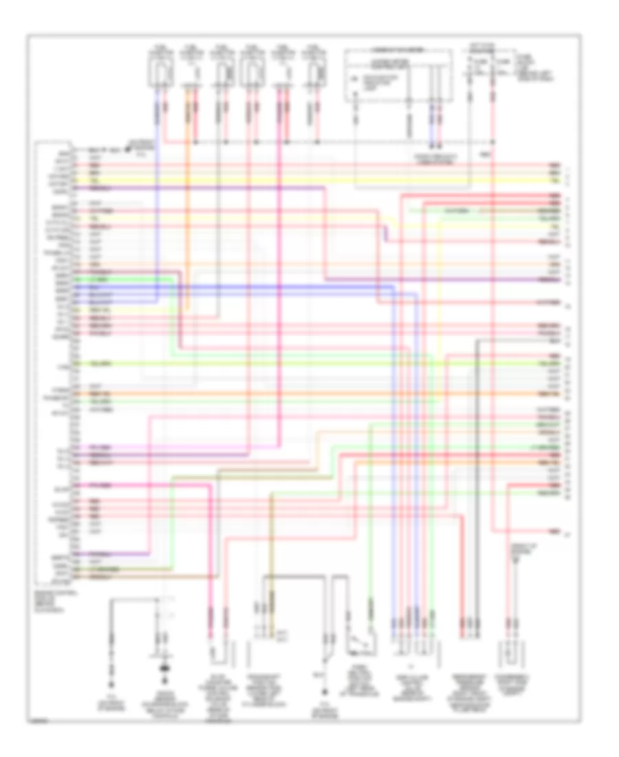
3.5L, Engine Performance Wiring Diagram (1 of 4) for Nissan Altima SE 2006
List of elements for 3.5L, Engine Performance Wiring Diagram (1 of 4) for Nissan Altima SE 2006:
- (a/t)
- (front of engine) f16
- (m/t)
- (on front of engine)
- 15p
- Af-h1
- Af-h2
- Af-un1
- Af-vm1
- Af-vm2
- Afip1
- Avcc
- Avcc2
- Combination meter
- Computer data lines system
- Condenser 2 (right side of engine compt)
- Crankshaft position sensor (pos) (lower left rear of cylinder block)
- Cvtc cil
- Cvtc cir
- Egr volume control valve (rear of engine compt)
- Egr1
- Egr2
- Egr3
- Egr4
- Egrts
- Engine control module (behind glove box)
- Enmn1
- Enmn2
- Evap
- Evap canister purge volume control solenoid valve (rear of intake manifold)
- F14
- F14 (on front of engine)
- Ftrps
- Fuel injector
- Fuse 10a
- Fuse block (j/b) (behind left side of dash)
- Gnd
- Hot in on or start
- Inj 1
- Inj 2
- Inj 3
- Inj 4
- Inj 5
- Inj 6
- Knk1
- Knock sensor (on engine block, below intake manifold)
- Malfunction indicator lamp
- Motor1
- Motor2
- Nca
- Neutral
- O2hrl
- O2hrr
- O2srl
- Park/ neutral position switch (left rear of transaxle)
- Pdpres
- Phase lh
- Phase rh
- Pnk
- Pos
- Ps pres
- Qa+
- Red
- Refrigerant pressure sensor (right front of engine compt, near radiator filler neck)
- Tps1
- Unified meter control unit
- V mot
- Vias
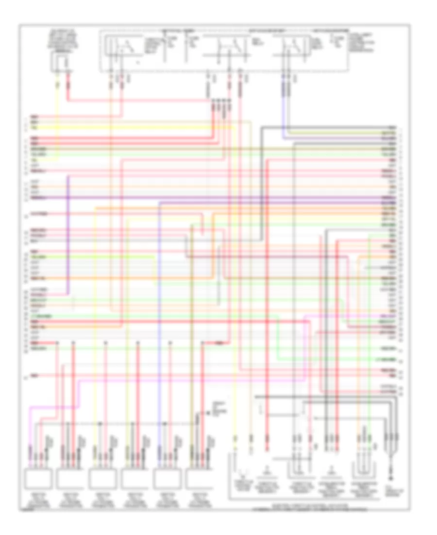
3.5L, Engine Performance Wiring Diagram (2 of 4) for Nissan Altima SE 2006
List of elements for 3.5L, Engine Performance Wiring Diagram (2 of 4) for Nissan Altima SE 2006:
- (front of engine) f16
- (on front of left cyl head) intake valve timing control solenoid valve (bank 2)
- Accelerator pedal position (app) sensor 1
- Accelerator pedal position (app) sensor 2
- E121
- E122
- E124
- E40
- Ecm relay
- Electric throttle control actuator (integral with throttle body, on rear of intake manifold)
- F14 (front of engine)
- F50
- Fuel pump relay
- Fuse 15a
- Hot at all times
- Hot in on or start
- Ignition coil 1 (w/ power transistor)
- Ignition coil 2 (w/ power transistor)
- Ignition coil 3 (w/ power transistor)
- Ignition coil 4 (w/ power transistor)
- Ignition coil 5 (w/ power transistor)
- Ignition coil 6 (w/ power transistor)
- Intelligent power distribution module engine room
- Nca
- Plug spark
- Red
- Spark plug
- Throttle control motor
- Throttle control motor relay
- Throttle position (tp) sensor 1
- Throttle position (tp) sensor 2
3.5L, Engine Performance Wiring Diagram (3 of 4) for Nissan Altima SE 2006
List of elements for 3.5L, Engine Performance Wiring Diagram (3 of 4) for Nissan Altima SE 2006:
- Air fuel ratio sensor 1 (bank 1) (on right side of engine, on exhaust manifold)
- Air fuel ratio sensor 1 (bank 2) (on left side of engine, on exhaust manifold)
- Camshaft position sensor (phase) (bank 1) (on rear of right cylinder head)
- Egr temperature sensor (on engine)
- Evap control system pressure sensor (below center rear of vehicle, near evap canister)
- F14 (front of engine)
- Fuse 10a
- Heated oxygen sensor 2 (bank 1) (on right exhaust downpipe)
- Heated oxygen sensor 2 (bank 2) (on left exhaust downpipe)
- Hot in on or start
- Intake valve timing control solenoid valve (bank 1) (front of right cyl head)
- Intelligent power distribution module engine room
- Mass airflow (maf) sensor (left side of engine compt, attached to air box)
- Red
- Vias control solenoid valve (top front of engine, on intake manifold)
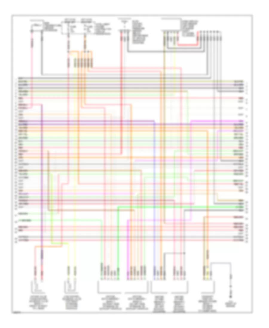
3.5L, Engine Performance Wiring Diagram (4 of 4) for Nissan Altima SE 2006
List of elements for 3.5L, Engine Performance Wiring Diagram (4 of 4) for Nissan Altima SE 2006:
- (behind left side of rear seat back)
- (front of engine) f14
- A/f-ia1
- A/f-ia2
- A/f-ip2
- Af-un2
- Aps1
- Aps2
- Ascdsw
- Avcc
- Avcc2
- B19
- Batt
- Bncsw
- Brake
- Camshaft position sensor (phase) (bank 2) (on rear of left cylinder head)
- Can l
- Can-h
- Cdcv
- Computer data lines system
- Condenser 1 (below left rear seat)
- Cruise control system
- Data link connector (below left side of dash)
- E14 (left side of engine compt, near battery)
- Engine control module (behind glove box)
- Engine coolant temperature sensor (upper rear of engine)
- Evap canister vent control valve (below center rear of vehicle, near evap canister)
- F14 (on front of engine)
- Fpr sol
- Front electronic controlled engine mount (lower front center of engine compt)
- Fuel level sensor unit & fuel pump (in fuel tank)
- Fuse & fusible link box (left front of engine compt, near battery)
- Fuse 10a
- Fuse 15a
- Fuse block (j/b) (behind left side of dash)
- Gnd
- Gnd 02
- Gnd a
- Gnd a2
- Hot at all times
- Ign 1
- Ign 2
- Ign 3
- Ign 4
- Ign 5
- Ign 6
- Ign sw
- Intelligent power distribution module engine room
- Kline
- M57 (behind right side of dash)
- Motrly
- Neut
- O2srr
- Pdpres
- Pnk
- Power steering oil pressure sensor (on power steering pump)
- Rear electronic controlled engine mount (lower rear center of engine compt)
- Red
- Ssoff
- Stop lamp switch (above brake pedal, on bracket)
- Tps2
EXTERIOR LIGHTS
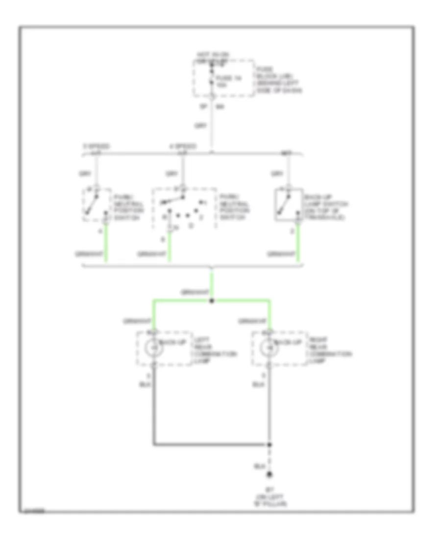
Backup Lamps Wiring Diagram for Nissan Altima SE 2006
List of elements for Backup Lamps Wiring Diagram for Nissan Altima SE 2006:
- 4 speed a/t
- 5 speed a/t
- B7 (on left "b" pillar)
- Back-up
- Back-up lamp switch (on top of transaxle)
- Fuse 14 10a
- Fuse block (j/b) (behind left side of dash)
- Hot in on or start
- Left rear combination lamp
- M/t
- Park/ neutral position switch
- Right rear combination lamp
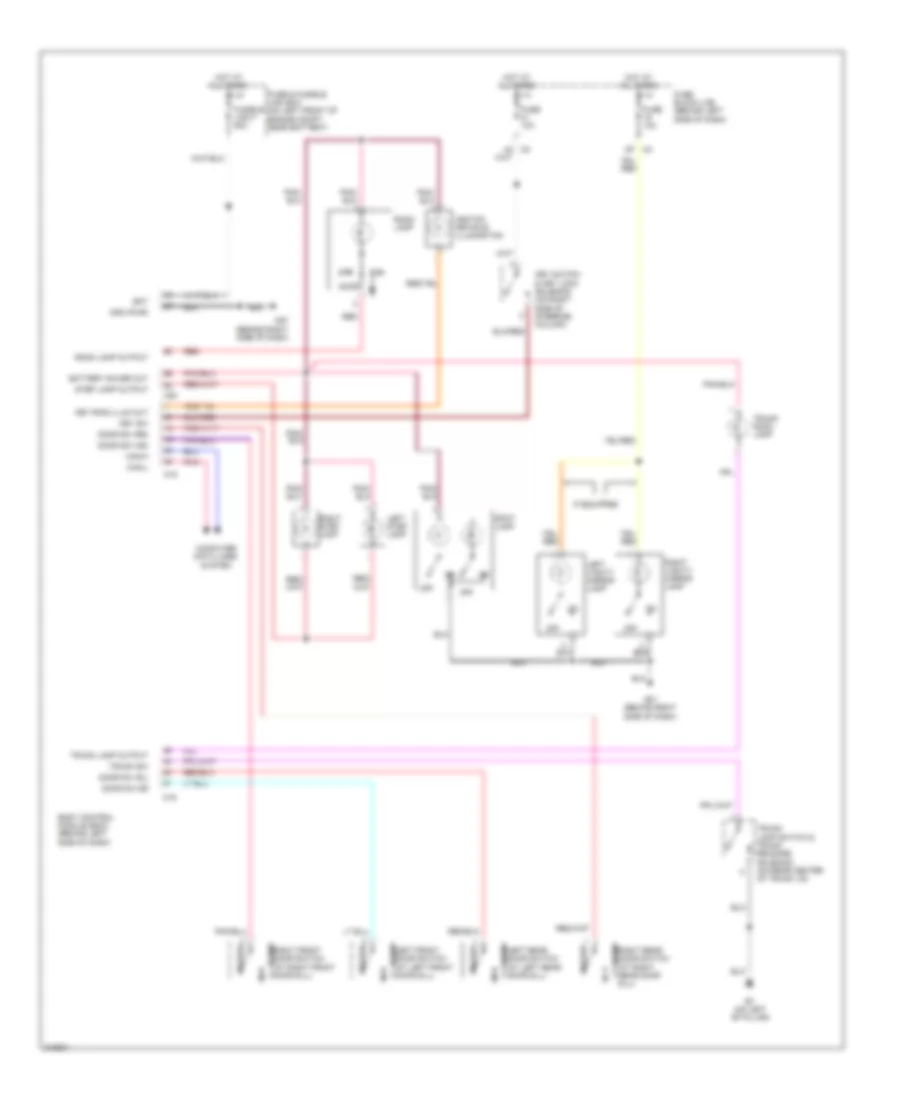
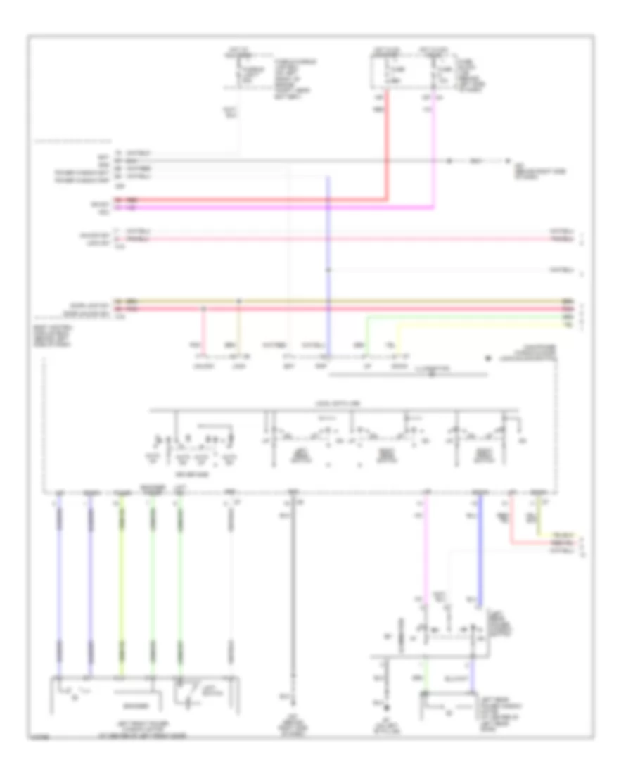
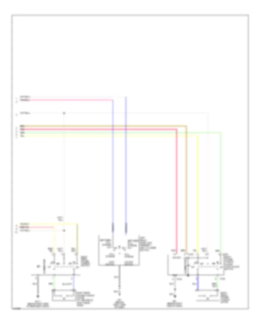
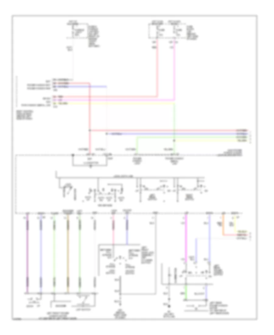
Exterior Lamps Wiring Diagram for Nissan Altima SE 2006
List of elements for Exterior Lamps Wiring Diagram for Nissan Altima SE 2006:
- (at left side of engine compartment, near battery) e15
- (on left "b" pillar) b7
- (w/bose: behind right side of rear seat back)
- (with odo/trip meter)
- 15p red
- Acc ign
- B7 (w/o bose) b117 (w/ bose) (w/o bose: on left "b" pillar)
- Bat
- Body control module (bcm) (behind left side of dash)
- Can-h
- Can-l
- Combi sw input 1
- Combi sw input 2
- Combi sw input 3
- Combi sw input 4
- Combi sw input 5
- Combi sw output 1
- Combi sw output 2
- Combi sw output 3
- Combi sw output 4
- Combi sw output 5
- Combination meter
- Combination switch
- Computer data lines system
- Cpu
- E121
- E122
- E30
- Flasher output (left)
- Flasher output (right)
- Fuse & fusible link box (on left front of engine compartment, near battery)
- Fuse 1 10a
- Fuse 14 10a
- Fuse 19 10a
- Fuse 20 10a
- Fuse 41 10a
- Fuse 6 10a
- Fuse block (j/b) (behind left side of dash)
- Fusible link f 50a
- Gnd
- Gnd (pwr)
- Hazard sw
- Hazard switch
- High mounted stop lamp
- Hot at all times
- Hot in acc or on
- Hot in on or start
- Input 1
- Input 2
- Input 3
- Input 4
- Input 5
- Intelligent power distribution module engine room (ipdm e/r) (on right front of engine compartment, behind headlight)
- Interior lights system
- Left front combination lamp
- Left license lamp
- Left rear combination lamp
- Left turn ind
- M18
- M20
- M57 (behind right side
- M57 (behind right side of dash)
- M61 (behind right side of dash)
- Nca
- Of dash)
- Output 1
- Output 2
- Output 3
- Output 4
- Output 5
- Park
- Pnk
- Red
- Right front combination lamp
- Right license lamp
- Right rear combination lamp
- Right turn ind
- Spoiler
- Stop
- Stop lamp switch (above brake pedal, on bracket)
- Tail
- Tail lamp relay
- Turn
- Unified meter control unit
- W/ rear spoiler
- W/o bose
- W/o rear
GROUND DISTRIBUTION
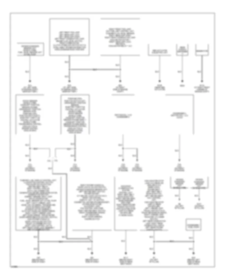
Ground Distribution Wiring Diagram for Nissan Altima SE 2006
List of elements for Ground Distribution Wiring Diagram for Nissan Altima SE 2006:
- 2.5l
- 3.5l
- Abs actuator & electric unit
- Air bag diagnosis sensor unit (shield wire)
- Air bag diagnosis sensor unit (shield wire), fuel level sensor unit & fuel pump
- B107 (on right "b" pillar)
- B117 (behind right side of rear seat back)
- B19 (behind left side of rear seat back)
- B202
- B5 (on left "b" pillar)
- B7 (on left "b" pillar)
- Condenser 1 (fuel pump)
- Condenser 2, ignition coil 1,2,3, 4,5 & 6
- E116 (at right front corner of engine compt)
- E126 (near abs actuator)
- E14 (at left side of engine compt, near battery)
- E15 (at left side of engine compt, near battery)
- E24 (at right side of engine compt)
- F14 (2.5l) (on front of engine)
- F14 (3.5l) (on front of engine)
- F15 (2.5l) (on front of engine)
- F16 (2.5l) (on front of engine)
- F16 (3.5l) (on front of engine)
- Fuse box (j/b), display control unit, illumination control switch, tcs on/off switch(w/tcs) heated seat relay, body control module, data link connector, combination meter, mode door motor, combination switch, ambient sensor, spot lamp, air mix door motor, fuel level sensor unit & fuel pump, left vanity mirror lamp, home link universal transceiver, nats antenna amplifier, sunroof motor assembly, auto anti-dazzling inside mirror, right vanity mirror lamp, left door mirror, triple meter door mirror remote control switch, main power window & door lock/unlock switch, trunk lid opener switch, shift lock control unit & left front door lock assembly (key cylinder switch)
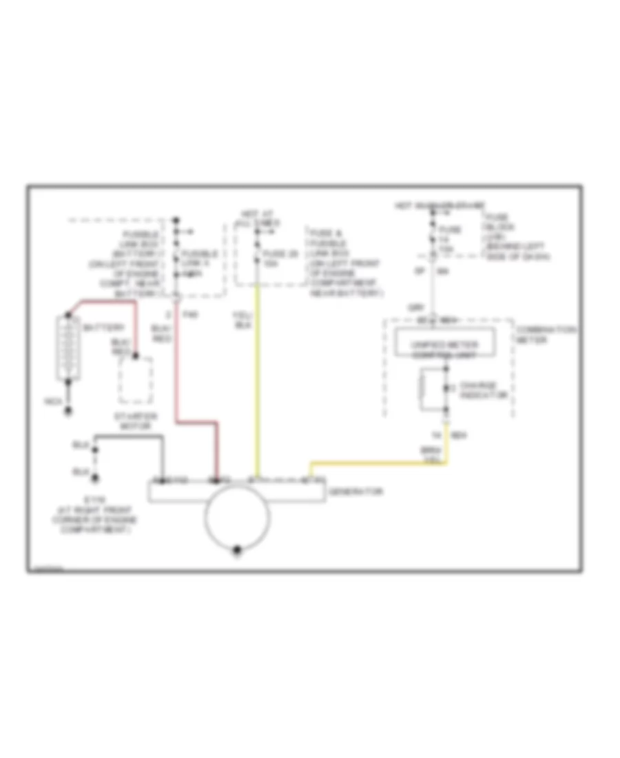
- Generator
- High mounted stop lamp (w/o rear air spoiler & w/o bose audio), power seat, left seat belt buckle switch, left heated seat, navi control unit, high mounted stop lamp (w/ rear air spoiler), left license lamp, trunk lamp switch & trunk release solenoid, right license lamp, trunk key cylinder switch, left rear combination lamp, right rear combination lamp & left rear power window switch
- Ignition coil 1-4 & condenser 2
- Knock sensor (shield wire), camshaft position sensor (phase), crankshaft position sensor (pos), park/neutral position switch(m/t), electric throttle control actuator (shield wire), transmission control module (tcm) & engine control module (ecm)
- Left front fog lamp, left headlamp (low), left headlamp (high), left front combination lamp, brake fluid level switch, front wiper motor, clutch interlock switch (m/t) & intelligent power distribution module engine room (ipdm e/r)
- M57 (behind right side of dash)
- M61 (behind right side of dash)
- Occupant classification system control unit, right seat belt buckle switch, right heated seat, bose speaker amplifier, right rear power window switch & high mounted stop lamp (w/o rear air spoiler, w/ bose audio)
- Park/neutral position switch (m/t), crankshaft position sensor, electric throttle control actuator (shield wire), knock sensor (shield wire), camshaft position sensor (phase) bank 1, camshaft position sensor (phase) bank 2, transmission control module (tcm) & engine control module (ecm)
- Rear window defogger (-)
- Right front fog lamp, daytime light control unit, washer fluid level sensor, right headlamp (high), right front combination lamp, cooling fan motor 1, right headlamp (low), ipdm e/r & cooling fan relay 1 & 3
- Right power window & door lock & unlock switch, air bag diagnosis sensor unit, left heated seat switch, power socket, a/t device, audio unit(w/ navi), front air control, display unit, av switch, cigarette lighter (power socket), intake door motor, glove box lamp, fan control amplifier, right heated seat switch, front passenger air bag off indicator, right door mirror & hazard switch
HEADLIGHTS
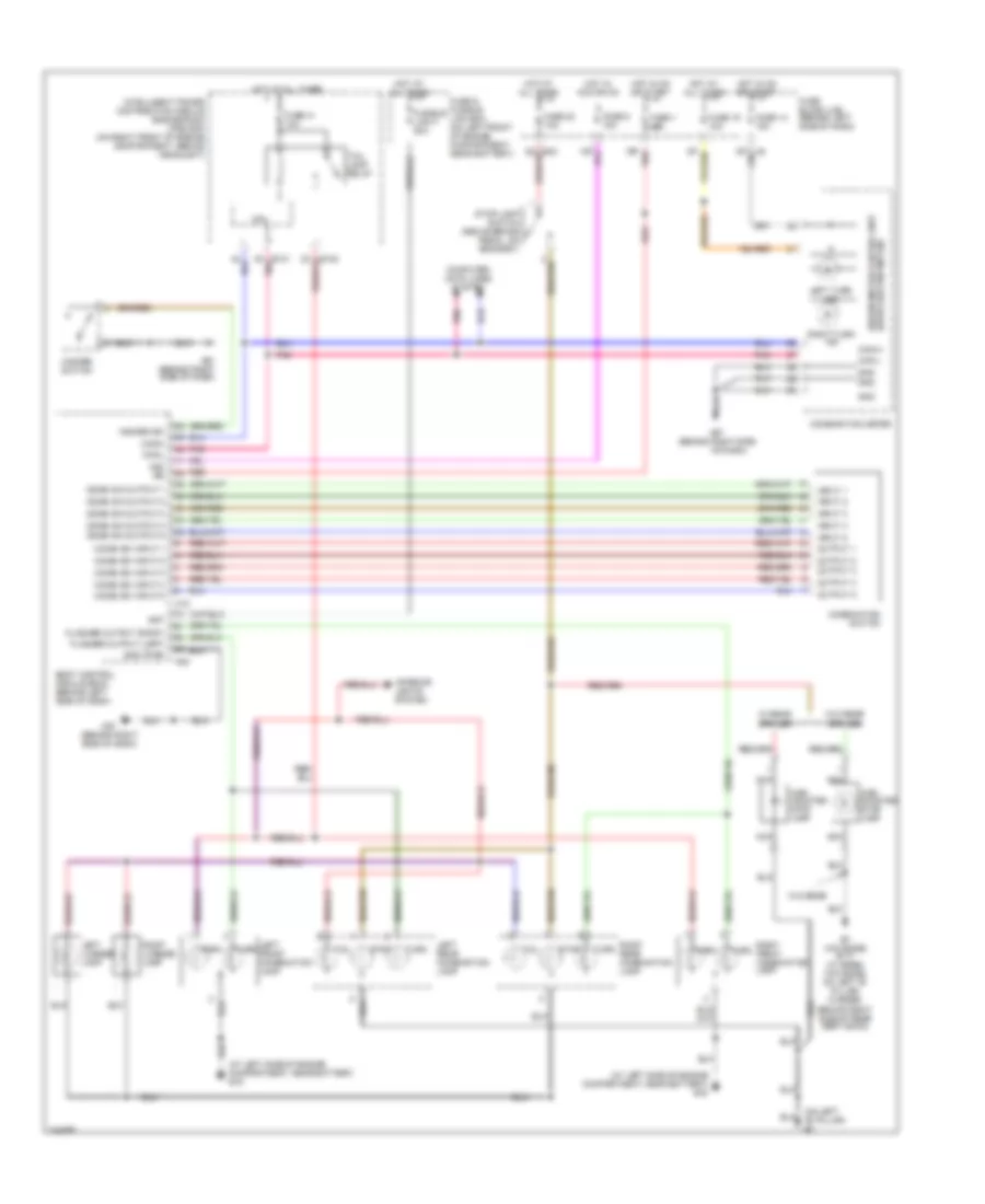
Headlights Wiring Diagram, with DRL for Nissan Altima SE 2006
List of elements for Headlights Wiring Diagram, with DRL for Nissan Altima SE 2006:
- (behind left side of dash)
- (halogen)
- (xenon)
- 12p
- 15p
- Acc
- Alt
- Auto light sensor (on upper left side of dash)
- Auto lt gnd
- Auto lt in
- Auto lt pwr
- Bat
- Body control module (bcm) (behind left side of dash)
- Can-h
- Can-l
- Comb sw in 1
- Comb sw in 2
- Comb sw in 3
- Comb sw in 4
- Comb sw in 5
- Comb sw out 1
- Comb sw out 2
- Comb sw out 3
- Comb sw out 4
- Comb sw out 5
- Combination meter
- Combination switch (lighting switch)
- Cpu
- Daytime light control unit (under left side of dash)
- Diode 1 (behind upper left side of dash)
- E102
- E103
- E104
- E121
- E122
- E124
- E15 (at left side of engine compt, near battery)
- E24 (at right side of engine compt)
- E30
- Front fog lamp relay
- Fuse & fusible link box (on left front of engine compt, near battery)
- Fuse 1 10a
- Fuse 10a
- Fuse 15a
- Fuse 43 15a
- Fuse 6 10a
- Fuse 9 10a
- Fuse block (j/b)
- Fusible link f 50a
- Generator
- Gnd
- Gnd lh hi
- Gnd rh hi
- H/l lh hi
- H/l lh hi fuse
- H/l lh hi gnd
- H/l rh hi
- H/l rh hi fuse
- H/l rh hi gnd
- Headlamp high relay
- Headlamp low relay
- Hid cont
- High beam ind
- Hot at all times
- Hot in on or acc
- Hot in on or start
- Hot in start
- Ign
- Input 1
- Input 2
- Input 3
- Input 4
- Input 5
- Intelligent power distribution module engine room (ipdm e/r) (on right front of engine compt, behind headlight)
- Left front fog lamp
- Left headlamp
- Left headlamp (high)
- Low
- M18
- M20
- M28
- M57 (behind right side of dash)
- Out
- Output 1
- Output 2
- Output 3
- Output 4
- Output 5
- Parking brake switch (at base of parking brake lever)
- Pkb sw
- Pnk
- Power
- Red
- Right front fog lamp
- Right headlamp
- Right headlamp (high)
- St sig
- Unified meter control unit
Headlights Wiring Diagram, without DRL for Nissan Altima SE 2006
List of elements for Headlights Wiring Diagram, without DRL for Nissan Altima SE 2006:
- (behind left side of dash)
- (halogen)
- (xenon)
- 12p
- 15p
- Acc
- Auto light sensor (on upper left side of dash)
- Auto lt gnd
- Auto lt in
- Auto lt pwr
- Bat
- Body control module (bcm) (behind left side of dash)
- Can-h
- Can-l
- Comb sw in 1
- Comb sw in 2
- Comb sw in 3
- Comb sw in 4
- Comb sw in 5
- Comb sw out 3
- Comb sw out 4
- Comb sw out 5
- Combi sw out 1
- Combi sw out 2
- Combination meter
- Combination switch (lighting switch)
- Control unit
- Cpu
- E121
- E122
- E124
- E15 (at left side of engine compt, near battery)
- E24 (at right side of engine compt)
- Front fog lamp relay
- Fuse & fusible link box (on left front of engine compt, near battery)
- Fuse 1 10a
- Fuse 36 15a
- Fuse 38 10a
- Fuse 40 10a
- Fuse 43 15a
- Fuse 45 15a
- Fuse 6 10a
- Fuse block (j/b)
- Fusible link f 50a
- Gnd
- Headlamp high relay
- Headlamp low relay
- Hid cont
- High beam ind
- Hot at all times
- Hot in acc or on
- Hot in on or start
- Ign
- Input 1
- Input 2
- Input 3
- Input 4
- Input 5
- Intelligent power distribution module engine room (ipdm e/r) (on right front of engine compt, behind headlight)
- Left front fog lamp
- Left headlamp
- Left headlamp (high)
- Low
- M18
- M20
- M28
- M57 (behind right side of dash)
- Out
- Out put 5
- Output 1
- Output 2
- Output 3
- Output 4
- Pnk
- Power
- Red
- Right front fog lamp
- Right headlamp
- Right headlamp (high)
- Unified meter
HORN
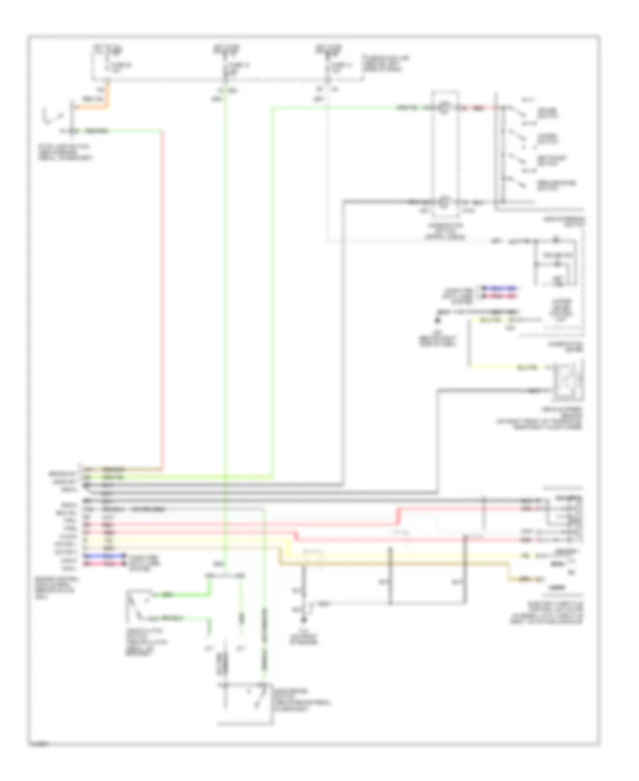
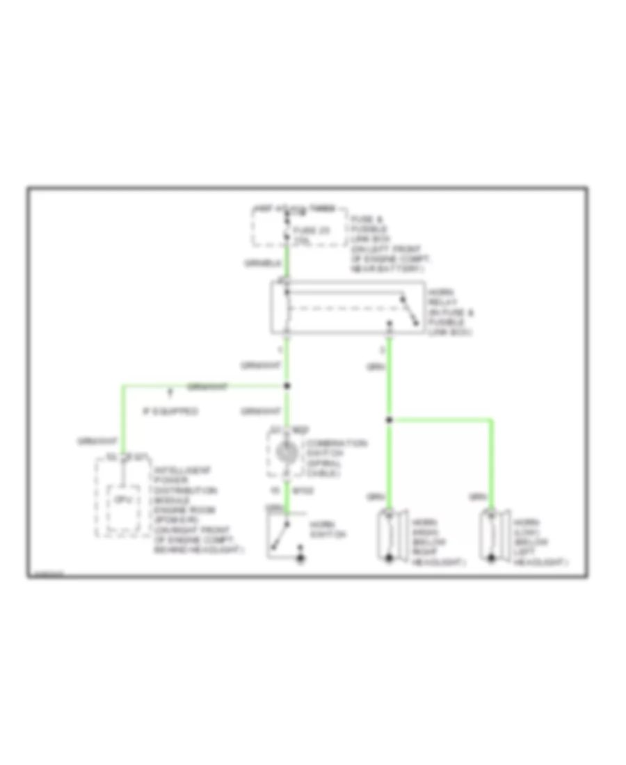
Horn Wiring Diagram for Nissan Altima SE 2006
List of elements for Horn Wiring Diagram for Nissan Altima SE 2006:
- Combination switch (spiral cable)
- Cpu
- E121
- Fuse & fusible link box (on left front of engine compt, near battery)
- Fuse 25 15a
- Horn switch
- Horn (high) (below right headlight)
- Horn (low) (below left headlight)
- Horn relay (in fuse & fusible link box)
- Hot at all times
- If equipped
- Intelligent power distribution module engine room (ipdm e/r) (on right front of engine compt, behind headlight)
- M102
- M30
INSTRUMENT CLUSTER
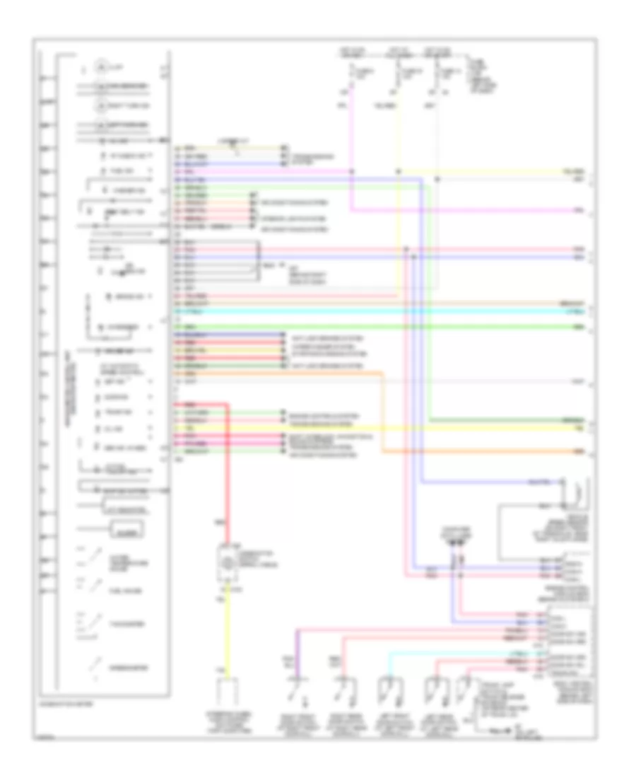
Instrument Cluster Wiring Diagram (1 of 2) for Nissan Altima SE 2006
List of elements for Instrument Cluster Wiring Diagram (1 of 2) for Nissan Altima SE 2006:
- (behind right
- (w/ automatic speed control)
- (w/abs)
- (w/odo/trip meter) unified meter control unit
- (w/tcs)
- (w/tcs) tcs off ind
- 12p
- 4 speed a/t
- A/t indicator
- Abs ind
- Air bag ind
- Air conditioning system
- Anti-lock brakes system
- At check ind
- B7 (on left "b" pillar)
- Body control module (bcm) (behind left side of dash)
- Brake ind
- Buzzer
- Can-h
- Can-l
- Charge ind
- Combination meter
- Combination switch (spiral cable)
- Computer data lines system
- Cruise ind
- Door ind
- Door sw (as)
- Door sw (dr)
- Door sw (rl)
- Door sw (rr)
- Engine control module (ecm) (behind glove box)
- Engine controls system
- Fuel gauge
- Fuel ind
- Fuse 14 10a
- Fuse 19 10a
- Fuse 6 10a
- Fuse block (j/b) (behind left side of dash)
- Gnd-a
- High beam ind
- Hot at all times
- Hot in on or acc
- Hot in on or start
- Illum
- Interior lights system
- Left front door switch (at left front door sill)
- Left rear door switch (at left rear door sill)
- Left turn ind
- M102
- M18
- M19
- M24
- M30
- M57
- Mil ind
- Oil ind
- Pnk
- Red
- Right front door switch (at right front door sill)
- Right rear door switch (at right rear door sill)
- Right turn ind
- Seat belt ind
- Set ind
- Shift interlock, navigation & sound systems transmissions system
- Side of dash)
- Slip ind
- Speedometer
- Starting/charging system
- Steering wheel audio control switches (trip computer)
- Tachometer
- Transmissions system
- Trunk ind
- Trunk lamp switch & trunk release solenoid (on rear center of trunk lid)
- Trunk sw
- Vehicle speed sensor (on right front of transaxle, near right axle flange)
- Washer ind
- Water temperature gauge
- Wiper/washer system
Instrument Cluster Wiring Diagram (2 of 2) for Nissan Altima SE 2006
List of elements for Instrument Cluster Wiring Diagram (2 of 2) for Nissan Altima SE 2006:
- Air bag diagnosis sensor unit (below center between seats)
- B113
- B117 (behind right side of rear seat back)
- B7 (on left "b" pillar)
- Brake fluid level switch (on master cylinder fluid reservoir)
- Buckle sw_lh
- Buckle sw_rh
- Can-h
- Can-l
- Cpu
- E121
- E15 (at left side of engine compt, near battery)
- Fuel consumption gauge
- Fuel level sensor unit sensor unit & fuel pump (fuel level sensor) (in fuel tank)
- Gnd
- Ipdm e/r (intelligent power distribution module engine room) (on right front of engine compartment, behind headlight)
- Left seat belt buckle switch (inside left front seat belt buckle)
- M35
- M57 (behind right side of dash)
- Oil pressure gauge
- Oil pressure sensor
- Oil pressure switch (2.5l: on right side of engine) (3.5l: on lower right front of cylinder block)
- Parking brake switch (at base of parking brake lever)
- Pnk
- Right seat belt buckle switch
- Seat belt air bag w/l
- Triple meter
- Vdd
- Volt meter
- Vout
INTERIOR LIGHTS
Courtesy Lamps Wiring Diagram for Nissan Altima SE 2006
List of elements for Courtesy Lamps Wiring Diagram for Nissan Altima SE 2006:
- B7 (on left "b" pillar)
- Bat
- Battery saver out
- Body control module (bcm) (behind left side of dash)
- Can-h
- Can-l
- Closed
- Computer data lines system
- Door
- Door sw (as)
- Door sw (rl)
- Door sw (rr)
- Door sw dr
- Fuse & fusible link box (on left front of engine compt, near battery)
- Fuse 10a
- Fuse block (j/b) (behind left side of dash)
- Fusible link f 50a
- Gnd (pwr)
- Hot at all times
- If equipped
- Ignition keyhole illumination
- Key ring illum out
- Key sw
- Key switch & key lock solenoid (on right side of steering column)
- Left front door switch (at left front door sill)
- Left rear door switch (at left rear door sill)
- Left step lamp
- Left vanity mirror lamp
- M18
- M19
- M20
- M57 (behind right side of dash)
- Off
- Open
- Pnk
- Red
- Right front door switch (at right front door sill)
- Right rear door switch (at right rear door sill)
- Right step lamp
- Right vanity mirror lamp
- Room lamp
- Room lamp output
- Spot lamp
- Step lamp output
- Trunk lamp output
- Trunk lamp switch & trunk release solenoid (on rear center of trunk lid)
- Trunk room lamp
- Trunk sw
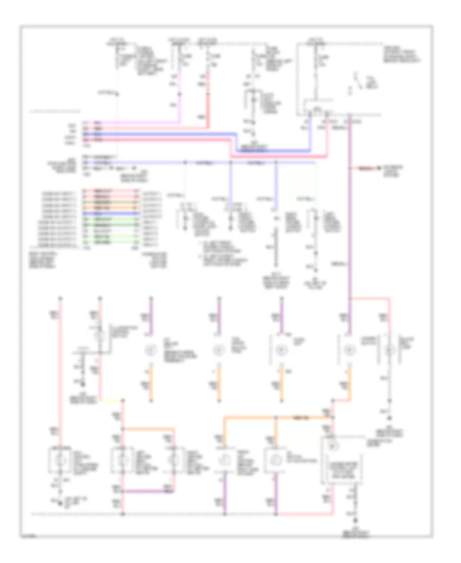
Instrument Illumination Wiring Diagram for Nissan Altima SE 2006
List of elements for Instrument Illumination Wiring Diagram for Nissan Altima SE 2006:
- (beneath gear selector lever assembly)
- (on left "b" pillar) b7
- 12p
- 15p
- A/t device (a/t)
- Acc
- Audio unit
- Auto anti- dazzling inside mirror
- Av switch (w/ navigation)
- B117 (behind right side of rear seat back)
- B41
- B7 (on left "b" pillar)
- Body control module (bcm) (behind left side of dash)
- Can-h
- Can-l
- Combi sw input 1
- Combi sw input 2
- Combi sw input 3
- Combi sw input 4
- Combi sw input 5
- Combi sw output 1
- Combi sw output 2
- Combi sw output 3
- Combi sw output 4
- Combi sw output 5
- Combination meter
- Combination switch (lighting switch)
- Cpu
- D105
- D106
- E121
- E122
- Exterior lights system
- Front air control (behind right side of dash)
- Front power window anti-pinch system
- Fuse & fusible link box (on left front of engine compt, near battery)
- Fuse 10a
- Fuse block (j/b) (behind left side of dash)
- Fusible link f 50a
- Glove box lamp
- Hazard switch
- Hot at all times
- Hot in acc or on
- Hot in on or start
- Ign
- Illumination control switch
- Input 1
- Input 2
- Input 3
- Input 4
- Input 5
- Ipdm e/r (on right front of engine compt, behind headlight)
- Left heated seat switch (w/ heated seats)
- Left rear power window switch
- M18
- M20
- M28
- M43
- M57 (behind right side of dash)
- M61 (behind right side of dash)
- Main power window & door lock/ unlock switch
- Navi control unit (if equipped) (in luggage compt)
- Output 1
- Output 2
- Output 3
- Output 4
- Output 5
- Pnk
- Power window anti-pinch system
- Red
- Right front power window switch
- Right heated seat switch (w/ heated seats)
- Right rear power window switch
- Tail lamp relay
- Tcs on/off switch (tcs)
- Unified meter control unit (with odo/ trip meter)
- W/ left & right
- W/ left front
NAVIGATION
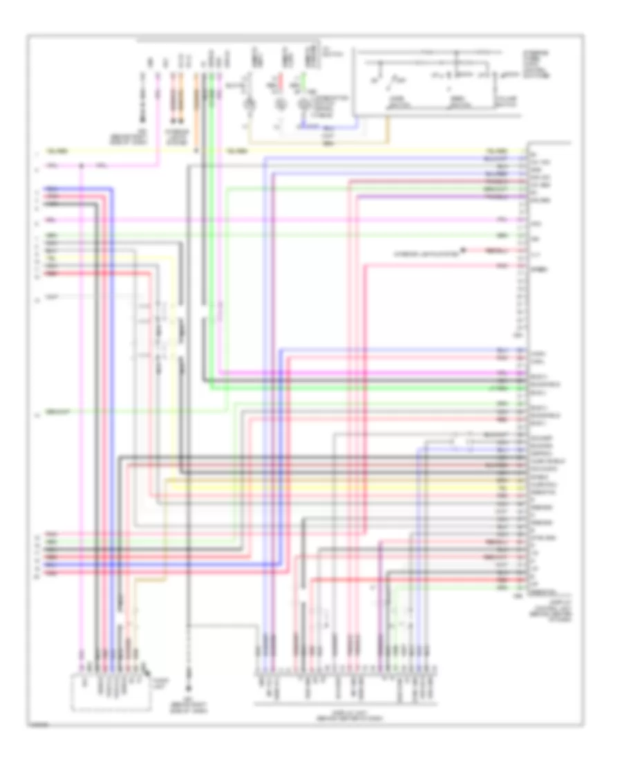
Navigation Wiring Diagram (1 of 2) for Nissan Altima SE 2006
List of elements for Navigation Wiring Diagram (1 of 2) for Nissan Altima SE 2006:
- 12p
- 16p
- Acc
- Ant gnd (gps)
- Ant sig (gps)
- B40
- B41
- B43
- B7 (on left "b" pillar)
- Body control module (bcm) (behind left side of dash)
- Bus (+)
- Bus (-)
- Can-h
- Can-l
- Combination meter
- Computer data lines system
- Exterior lights system
- Fuse 10a
- Fuse block (j/b) (behind left side of dash)
- Gnd
- Gps antenna
- Hot at all times
- Hot in acc or on
- Hot in on or start
- Ign
- Ill
- Ill+
- Interior lights system
- M18
- M24
- Navi control unit (in luggage compt)
- Nca
- Pnk
- Red
- Rgb gnd
- Rgb sync
- Shield
- Speed
- Voice (+)
- Voice (-)
Navigation Wiring Diagram (2 of 2) for Nissan Altima SE 2006
List of elements for Navigation Wiring Diagram (2 of 2) for Nissan Altima SE 2006:
- Acc
- Audio shield
- Audio unit
- Audio-dcu
- Av switch
- B (down) remote
- Bus
- Bus (+)
- Bus (-)
- Bus gnd
- Bus shield
- Can-h
- Can-l
- Combination switch (spiral cable)
- Dcu-audio
- Dcu-dsp
- Display control unit (behind center of dash)
- Display unit (behind center of dash)
- Down
- Dsp-dcu
- Gnd
- Ign
- Ill (+)
- Ill (-)
- Ill+
- Interior lights system
- Inv gnd
- Inv vcc
- M102
- M30
- M43
- M45
- M61 (behind right side of dash)
- M94
- M95
- Mode switch
- Nca
- Off
- Pnk
- Red
- Remote a (up)
- Remote gnd c
- Rgb gnd
- Rgb sync
- Seek switch
- Shield
- Sig gnd
- Sig vcc
- Sign gnd
- Sign vcc
- Speed
- Steering wheel audio control switches
- Sync gnd
- Voice (+)
- Voice (-)
- Volume switch
POWER DISTRIBUTION
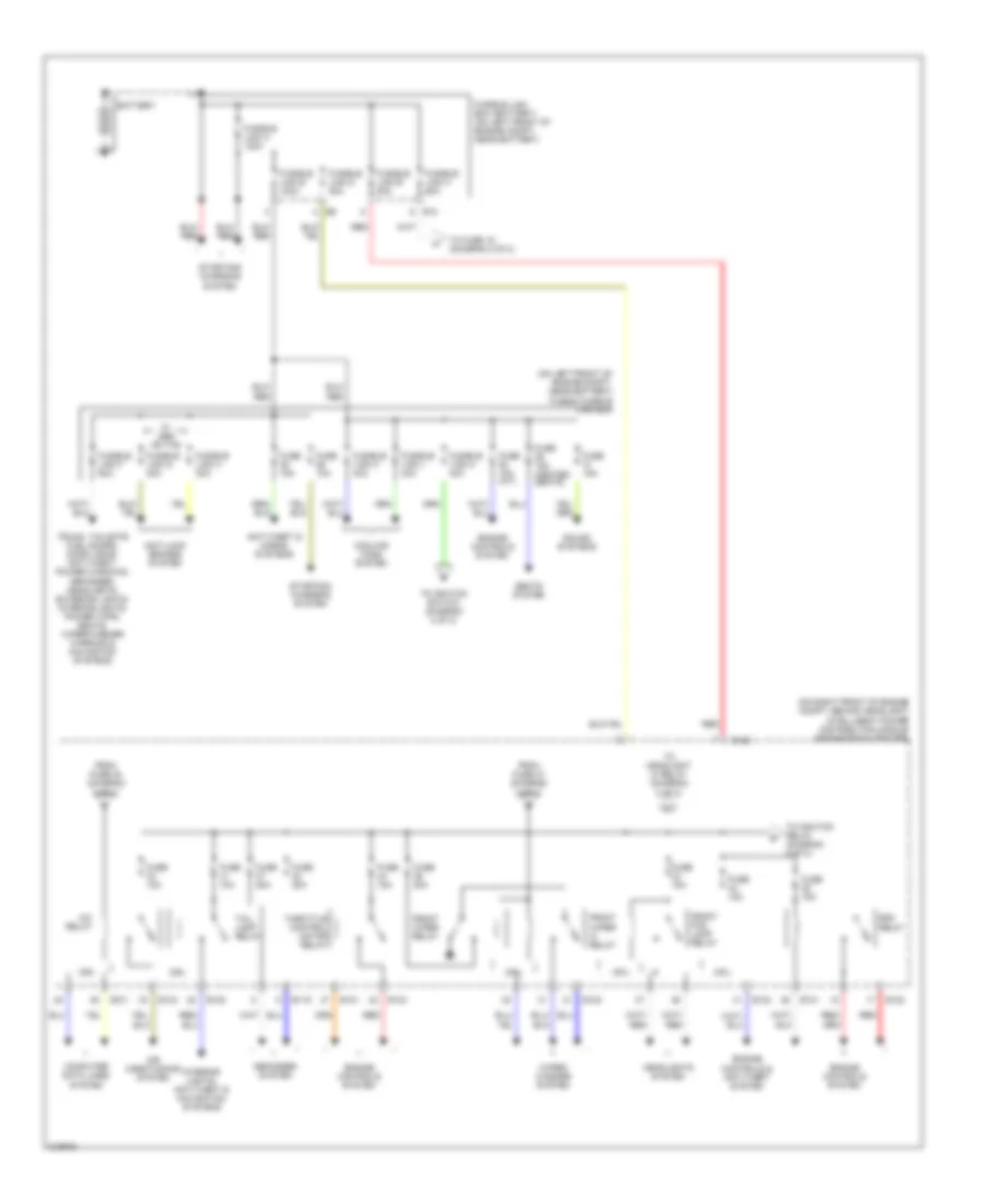
Power Distribution Wiring Diagram (1 of 2) for Nissan Altima SE 2006
List of elements for Power Distribution Wiring Diagram (1 of 2) for Nissan Altima SE 2006:
- (on left front of engine compt, near battery) fuse & fusible link box
- (on right front of engine compt, behind headlight) intelligent power distribution module engine room (ipdm e/r)
- A/c relay
- Air conditioning system
- Anti-lock brakes system
- Anti-theft & horns systems
- Battery
- Computer data lines system
- Cooling fans system
- Cpu
- Defogger system
- E10
- E119
- E120
- E121
- E122
- E124
- Ecm relay
- Engine controls & anti-theft system
- Engine controls system
- From fuse 47 (diagram 2 of 2)
- From fuse 48 (diagram 2 of 2)
- Front fog lamp relay
- Front wiper hi relay
- Front wiper relay
- Fuse 10a
- Fuse 10a (a/t)
- Fuse 15a
- Fuse 15a (heated seats)
- Fuse 20a
- Fusible link a 120a
- Fusible link b 80a
- Fusible link box (battery) (on left front of engine compt, near battery)
- Fusible link c 60a
- Fusible link d 80a
- Fusible link e 100a
- Fusible link f 50a
- Fusible link g 30a
- Fusible link h 30a
- Fusible link k 40a
- Fusible link l 40a
- Fusible link m 40a
- Headlights system
- Interior lights, anti-theft & navigation systems
- Red
- Seats system
- Sound systems
- Starting/ charging system
- Tail lamp relay
- Throttle control motor relay
- To fuse 19 (diagram 2 of 2)
- To headlight hi relay (diagram 2 of 2)
- To ignition relay (diagram 2 of 2)
- To ignition switch (diagram 2 of 2)
- Trunk, tailgate fuel doors, door locks, anti-theft, power windows, defogger, headlights, exterior lights, interior lights, power tops, seats, wiper/washer warning & navigation systems
- W/ abs or tcs
- Wiper/ washer system
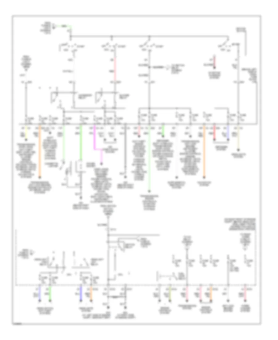
Power Distribution Wiring Diagram (2 of 2) for Nissan Altima SE 2006
List of elements for Power Distribution Wiring Diagram (2 of 2) for Nissan Altima SE 2006:
- (behind left side of dash) fuse block (j/b)
- (diagram 1 of 2)
- (on right front of engine compt, behind headlight) intelligent power distribution module engine room (ipdm e/r)
- 10p
- 11p
- 12p
- 15p
- 16p
- 4n m3
- Acc
- Acc on
- Accessory relay
- Air conditioning system
- Anti-lock brakes system
- Anti-theft, engine controls systems, navigation systems, power
- Blower relay
- Cigarette lighter
- Cpu
- Defogger system
- Defogger, shift interlock, transmissions, door locks, engine controls, power windows, air conditioning, seats, navigation & computer data lines systems
- Door locks, anti-theft, defogger, mirrors, power windows, headlights, exterior lights, interior lights, power tops, sound, navigation, body computer & instrument cluster systems
- E118
- E121
- E122
- E124
- E15 (at left side of engine compt, near battery)
- E24 (at right side of engine compt)
- E30
- E31
- E32
- Engine controls system
- From fuse 35 (diagram 1 of 2)
- From fuse 43 (diagram 1 of 2)
- From fusible link c (diagram 1 of 2)
- From fusible link m b
- From ignition switch (diagram 2 of 2)
- Fuel pump relay
- Fuse 10a
- Fuse 10a (w/ abs or tcs)
- Fuse 15a
- Headlight high relay
- Headlight low relay
- Headlights & anti-theft systems
- Headlights system
- Ig1
- Ig2
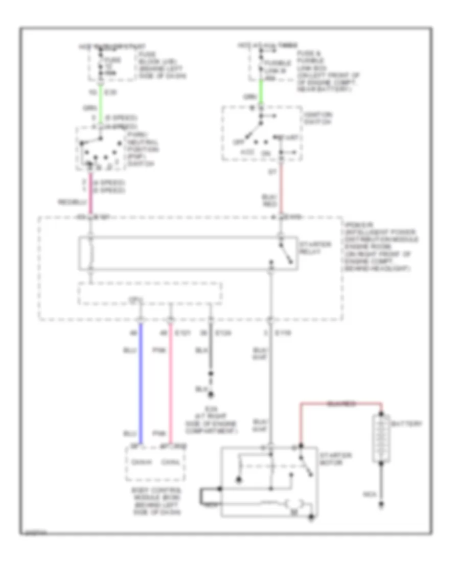
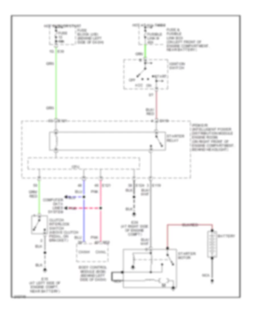
- Ignition relay
- Ignition switch
- M57 (behind right side of dash)
- M61 (behind right side of dash)
- Navigation system
- Off
- Power socket
- Red
- Shift interlock, navigation, door locks, anti-theft, interior lights & warning systems
- Start
- Starting/ charging system
- To a/c relay (diagram 1 of 2)
- To front wiper hi relay (diagram 1 of 2)
- To ignition relay (diagram 2 of 2)
- Transmissions system
- Transmissions, anti-lock brakes, engine controls & exterior lights systems
- Transmissions, door locks, anti-theft, body computer, instrument cluster, engine controls, air conditioning, exterior lights, interior lights, warning, navigation & systems
- Transmissions, engine controls & starting/ charging systems
- Windows interior, exterior & head lights power tops wiper & washer system
- Wiper/ washer system
POWER DOOR LOCKS
Power Door Locks Wiring Diagram, with Driver Side Anti-Pinch System for Nissan Altima SE 2006
List of elements for Power Door Locks Wiring Diagram, with Driver Side Anti-Pinch System for Nissan Altima SE 2006:
- 12p m4
- 15p
- 4n m3
- Acc
- Bat
- Bat fuse
- Bat saver out
- Between full stroke & n
- Body control module (bcm) (behind left side of dash)
- Can-h
- Can-l
- Cdl lock sw
- Cdl unlock sw
- Closed
- D105
- Data link connector (below left side of dash)
- Door lock & unlock switch
- Door lock out (all)
- Door unlock out (as/rr)
- Door unlock out (dr)
- Dr sw as
- Dr sw dr
- E121
- Full stroke
- Fuse & fusible link box (on left front of engine compartment, near battery)
- Fuse 10a
- Fuse block (j/b) (behind left side of dash)
- Fusible link f 50a
- Gnd
- Hot at all times
- Hot in acc or on
- Hot in on or start
- Ign sw
- Inserted
- Interior lights system
- Ipdm e/r (on right front of engine compt, behind headlight)
- Key cyl sw (lock)
- Key cyl sw (unlock)
- Key ring ill output
- Key sw
- Key switch & key lock solenoid (on right side of steering column)
- Left front door lock actuator (at rear of left front door)
- Left front door lock assembly (key cylinder switch)
- Left front door switch (at left front door sill)
- Left rear door lock actuator (at rear of left rear door)
- Left rear door switch (at left rear door sill)
- Lock
- Lock sw
- Lock switch
- M18
- M19
- M20
- M57 (behind right side of dash)
- M61 (behind right side of dash)
- Main power window & door lock/unlock switch
- Open
- Pnk
- Red
- Removed
- Right front door lock actuator (at rear of right front door)
- Right front door switch (at right front door sill)
- Right power window & door lock/unlock switch
- Right rear door lock actuator (at rear of right rear door)
- Right rear door switch (at right rear door sill)
- Rl door sw
- Room lamp out
- Rr door sw
- Step lamp out
- Unlock
- Unlock sw
- Unlock switch
Power Door Locks Wiring Diagram, with Driver and Passenger Side Anti-Pinch System for Nissan Altima SE 2006
List of elements for Power Door Locks Wiring Diagram, with Driver and Passenger Side Anti-Pinch System for Nissan Altima SE 2006:
- 12p m4
- 15p
- 4n m3
- Acc
- Bat
- Bat fuse
- Bat saver out
- Between full stroke & n
- Body control module (bcm) (behind left side of dash)
- Can-h
- Can-l
- Closed
- Com
- D105
- D106
- Data link connector (below left side of dash)
- Door lock & unlock switch
- Door lock out (all)
- Door unlock out (as/rr)
- Door unlock out (dr)
- Dr sw as
- Dr sw dr
- E121
- Full stroke
- Fuse & fusible link box (on left front of engine compt, near battery)
- Fuse 10a
- Fuse block (j/b) (behind left side of dash)
- Fusible link f 50a
- Hot at all times
- Hot in acc or on
- Hot in on or start
- Ign sw
- Inserted
- Interior lights system
- Ipdm e/r (on right front of engine compt, behind headlight)
- Key ring ill output
- Key sw
- Key switch & key lock solenoid (on right side of steering column)
- Left front door lock actuator (at rear of left front door)
- Left front door lock assembly (key cylinder switch)
- Left front door switch (at left front door sill)
- Left rear door lock actuator (at rear of left rear door)
- Left rear door switch (at left rear door sill)
- Lock
- Lock sw
- Lock switch
- M18
- M19
- M20
- M57 (behind right side of dash)
- M61 (behind right side of dash)
- Main power window & door lock/unlock switch
- Open
- Pnk
- Pwr window serial link
- Red
- Removed
- Right front door lock actuator (at rear of right front door)
- Right front door switch (at right front door sill)
- Right power window & door lock/unlock switch
- Right rear door lock actuator (at rear of right rear door)
- Right rear door switch (at right rear door sill)
- Rl door sw
- Room lamp out
- Rr door sw
- Step lamp out
- Unlock
- Unlock sw lock sw
- Unlock switch
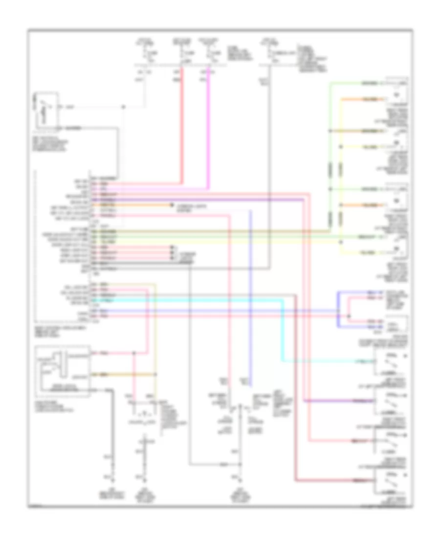
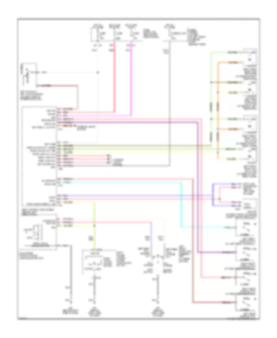
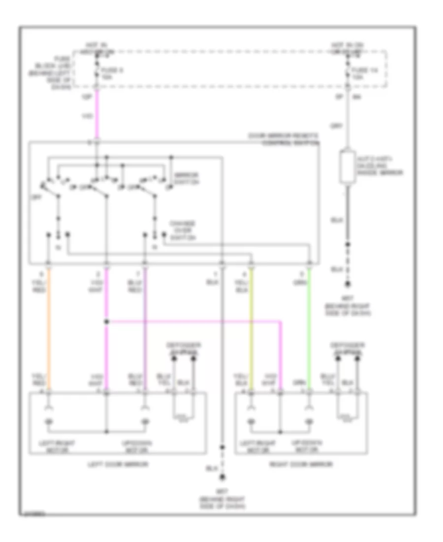
POWER MIRRORS
Power Mirror Wiring Diagram for Nissan Altima SE 2006
List of elements for Power Mirror Wiring Diagram for Nissan Altima SE 2006:
- 12p
- Auto anti- dazzling inside mirror
- Change over switch
- Defogger system
- Door mirror remote control switch
- Fuse 14 10a
- Fuse 6 10a
- Fuse block (j/b) (behind left side of dash)
- Hot in acc or on
- Hot in on or start
- Left door mirror
- Left/right motor
- M57 (behind right side of dash)
- Mirror switch
- Off
- Right door mirror
- Up/down motor
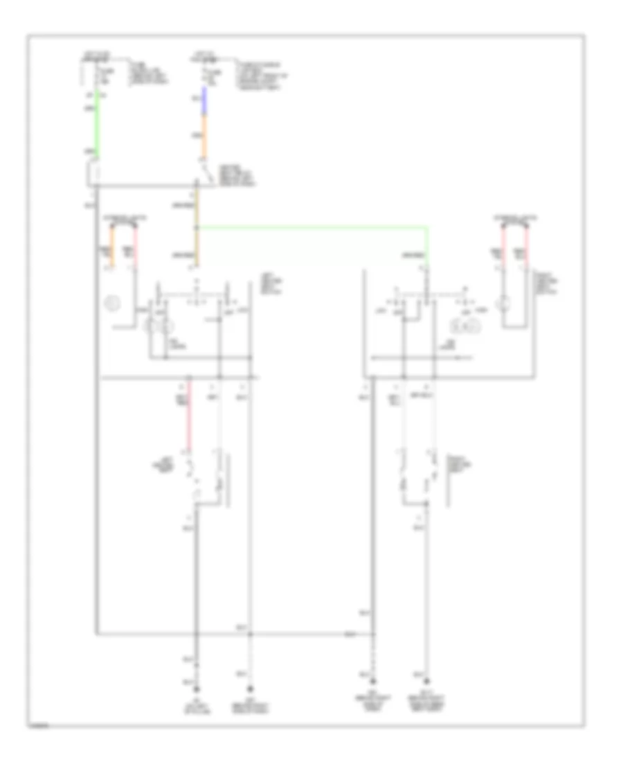
POWER SEATS
Heated Seats Wiring Diagram for Nissan Altima SE 2006
List of elements for Heated Seats Wiring Diagram for Nissan Altima SE 2006:
- B117 (behind right side of rear seat back)
- B7 (on left ``b" pillar)
- Fuse & fusible link box (on left front of engine compt, near battery)
- Fuse 10a
- Fuse 15a
- Fuse block (j/b) (behind left side of dash)
- Heated seat relay (behind left side of dash)
- High
- High off
- Hot at all times
- Hot in on or start
- Ind lamps
- Interior lights system
- Left heated seat
- Left heated seat switch
- Low
- Low off
- M57 (behind right side of dash)
- M61 (behind right side of dash)
- Off
- Right heated seat
- Right heated seat switch
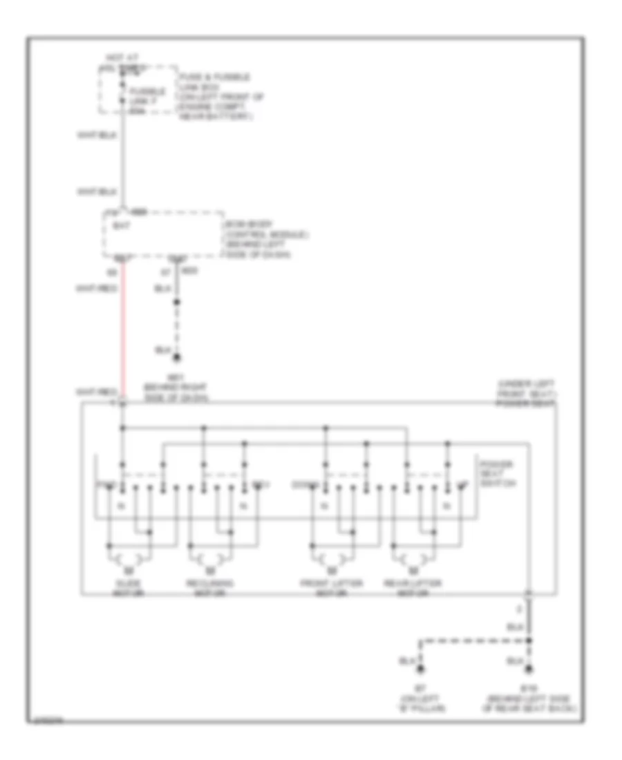
Power Seat Wiring Diagram for Nissan Altima SE 2006
List of elements for Power Seat Wiring Diagram for Nissan Altima SE 2006:
- (under left front seat) power seat
- B19 (behind left side of rear seat back)
- B7 (on left ``b" pillar)
- Bat
- Bcm (body control module) (behind left side of dash)
- Down
- Front lifter motor
- Fuse & fusible link box (on left front of engine compt, near battery)
- Fusible link f 50a
- Fwd
- Gnd
- Hot at all times
- M20
- M61 (behind right side of dash)
- Power seat switch
- Rear lifter motor
- Reclining motor
- Rev
- Slide motor
POWER TOP/SUNROOF
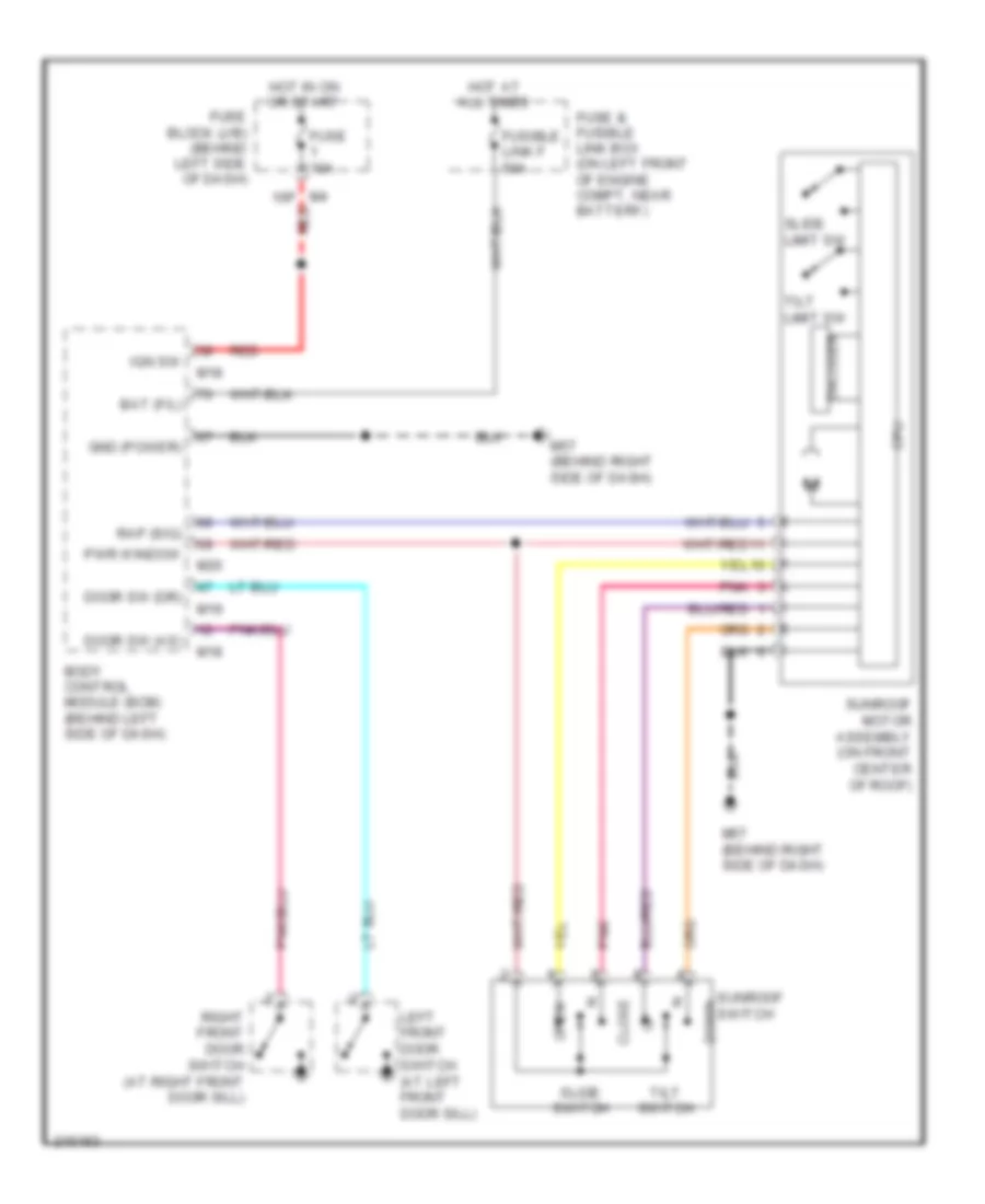
Power Top/Sunroof Wiring Diagram for Nissan Altima SE 2006
List of elements for Power Top/Sunroof Wiring Diagram for Nissan Altima SE 2006:
- 15p red
- Bat (f/l)
- Body control module (bcm) (behind left side of dash)
- Close
- Cpu
- Door sw (as)
- Door sw (dr)
- Down
- Encoder
- Fuse & fusible link box (on left front of engine compt, near battery)
- Fuse 10a
- Fuse block (j/b) (behind left side of dash)
- Fusible link f 50a
- Gnd (power)
- Hot at all times
- Hot in on or start
- Ign sw
- Left front door switch (at left front door sill)
- M18
- M19
- M20
- M57 (behind right side of dash)
- Open
- Pnk
- Pwr window
- Rap (sig)
- Red
- Right front door switch (at right front door sill)
- Slide limit sw
- Slide switch
- Sunroof motor assembly (on front center of roof)
- Sunroof switch
- Tilt limit sw
- Tilt switch
POWER WINDOWS
Power Windows Wiring Diagram, with Driver Side Anti-Pinch System (1 of 2) for Nissan Altima SE 2006
List of elements for Power Windows Wiring Diagram, with Driver Side Anti-Pinch System (1 of 2) for Nissan Altima SE 2006:
- 12p m4
- 15p
- Acc
- Auto dn
- Auto up
- B7 (on left "b" pillar)
- Bat
- Body control module (bcm) (behind left side of dash)
- Door lock sw
- Door unlock sw
- Down
- Driver side
- Encoder
- Encoder power
- Fuse & fusible link box (on left front of engine compt, near battery)
- Fuse 10a
- Fuse block (j/b) (behind left side of dash)
- Fusible link f 50a
- Gnd
- Hot at all times
- Hot in acc or on
- Hot in on or start
- Ign sw
- Illumination
- Left front power window motor (at center of left front door)
- Left rear power window motor (at center of left rear door)
- Left rear power window switch
- Left rear switch
- Limit sw
- Limit switch
- Local data line
- Lock
- Lock sw
- M18
- M19
- M20
- M57 (behind right side of dash)
- Main power window & door lock/unlock switch
- Pnk
- Power window bat
- Power window rap
- Pulse
- Rap
- Red
- Right front switch
- Right rear switch
- Unlock
- Unlock sw
Power Windows Wiring Diagram, with Driver Side Anti-Pinch System (2 of 2) for Nissan Altima SE 2006
List of elements for Power Windows Wiring Diagram, with Driver Side Anti-Pinch System (2 of 2) for Nissan Altima SE 2006:
- B117 (behind right side of rear seat back)
- Between full stroke & n
- D105
- D106
- Full stroke
- Gnd
- Illumination
- Left front door lock assembly (key cylinder switch)
- Lock
- Lock switch
- M57 (behind right side of dash)
- M61 (behind right side of dash)
- Pnk
- Right front power window motor
- Right power window & door lock/unlock switch
- Right rear power window motor (at center of right rear door)
- Right rear power window switch
- Unlock
- Unlock switch
Power Windows Wiring Diagram, with Driver and Passenger Side Anti-Pinch System (1 of 2) for Nissan Altima SE 2006
List of elements for Power Windows Wiring Diagram, with Driver and Passenger Side Anti-Pinch System (1 of 2) for Nissan Altima SE 2006:
- 12p m4
- 15p
- Acc
- Auto dn
- Auto up
- B7 (on left "b" pillar)
- Bat
- Between full stroke & n
- Body control module (bcm) (behind left side of dash)
- Down
- Driver side
- Encoder
- Encoder power
- Full stroke
- Fuse & fusible link box (on left front of engine compt, near battery)
- Fuse 10a
- Fuse block (j/b) (behind left side of dash)
- Fusible link f 50a
- Gnd
- Hot at all times
- Hot in acc or on
- Hot in on or start
- Ign sw
- Illumination
- Left front door lock assembly (key cylinder switch)
- Left front power window motor (at center of left front door)
- Left rear power window motor (at center of left rear door)
- Left rear power window switch
- Left rear switch
- Limit sw
- Limit switch
- Local data line
- Lock sw
- Lock switch
- Locked
- M18
- M20
- M57 (behind right side of dash)
- Main power window & door lock/unlock switch
- Power window bat
- Power window lock
- Power window rap
- Power window serial link
- Pulse
- Pwr window serial link
- Rap
- Red
- Right rear switch
- Unlock sw
- Unlock switch
- Unlocked
Power Windows Wiring Diagram, with Driver and Passenger Side Anti-Pinch System (2 of 2) for Nissan Altima SE 2006
List of elements for Power Windows Wiring Diagram, with Driver and Passenger Side Anti-Pinch System (2 of 2) for Nissan Altima SE 2006:
- Auto dn
- Auto up
- B117 (behind right side of rear seat back)
- Down
- Encoder
- Encoder power
- Gnd
- Illumination
- Limit sw
- Limit switch
- Local data line
- M61 (behind right side of dash)
- Pins 1-8 = d106
- Pins 9-20 = d105
- Pulse
- Right front power window motor
- Right power window & door lock/ unlock switch
- Right rear power window motor (at center of right rear door)
- Right rear power window switch
RADIO
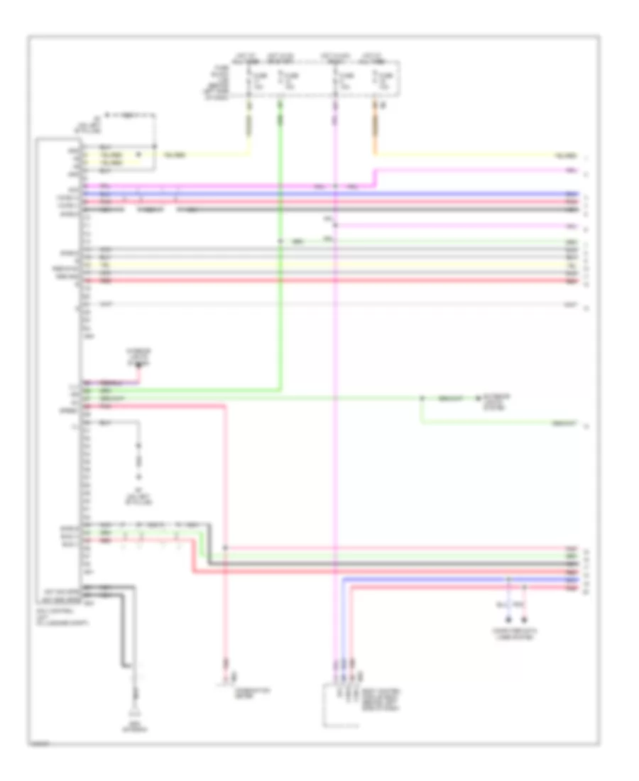
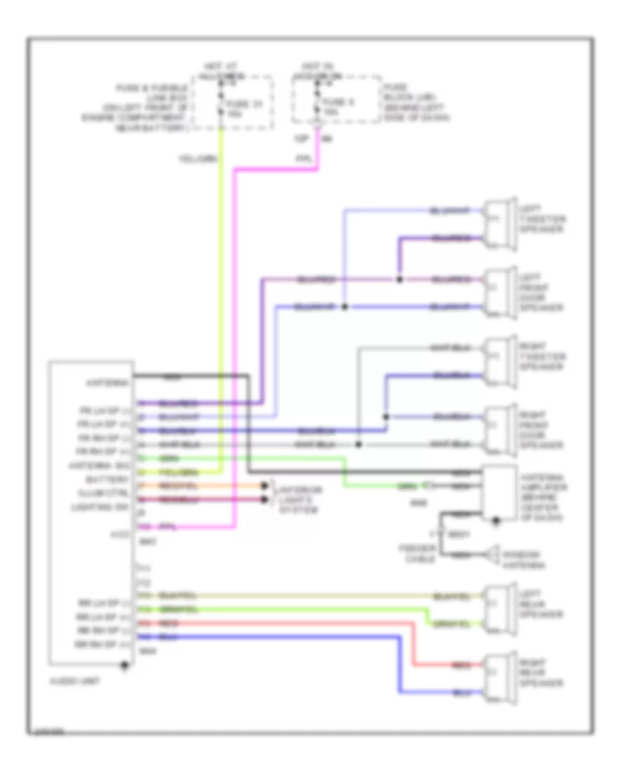
Base Radio Wiring Diagram for Nissan Altima SE 2006
List of elements for Base Radio Wiring Diagram for Nissan Altima SE 2006:
- (+)
- (-)
- 12p
- Acc
- Antenna
- Antenna amplifier (behind center of dash)
- Antenna sig
- Audio unit
- Battery
- Feeder cable
- Fr lh sp (+)
- Fr lh sp (-)
- Fr rh sp (+)
- Fr rh sp (-)
- Fuse & fusible link box (on left front of engine compartment, near battery)
- Fuse 31 15a
- Fuse 6 10a
- Fuse block (j/b) (behind left side of dash)
- Hot at all times
- Hot in acc or on
- Illum ctrl
- Interior lights system
- Left front door speaker
- Left rear speaker
- Left tweeter speaker
- Lighting sw
- M43
- M44
- M48
- M501
- Nca
- Red
- Right front door speaker
- Right rear speaker
- Right tweeter speaker
- Rr lh sp (+)
- Rr lh sp (-)
- Rr rh sp (+)
- Rr rh sp (-)
- Window antenna
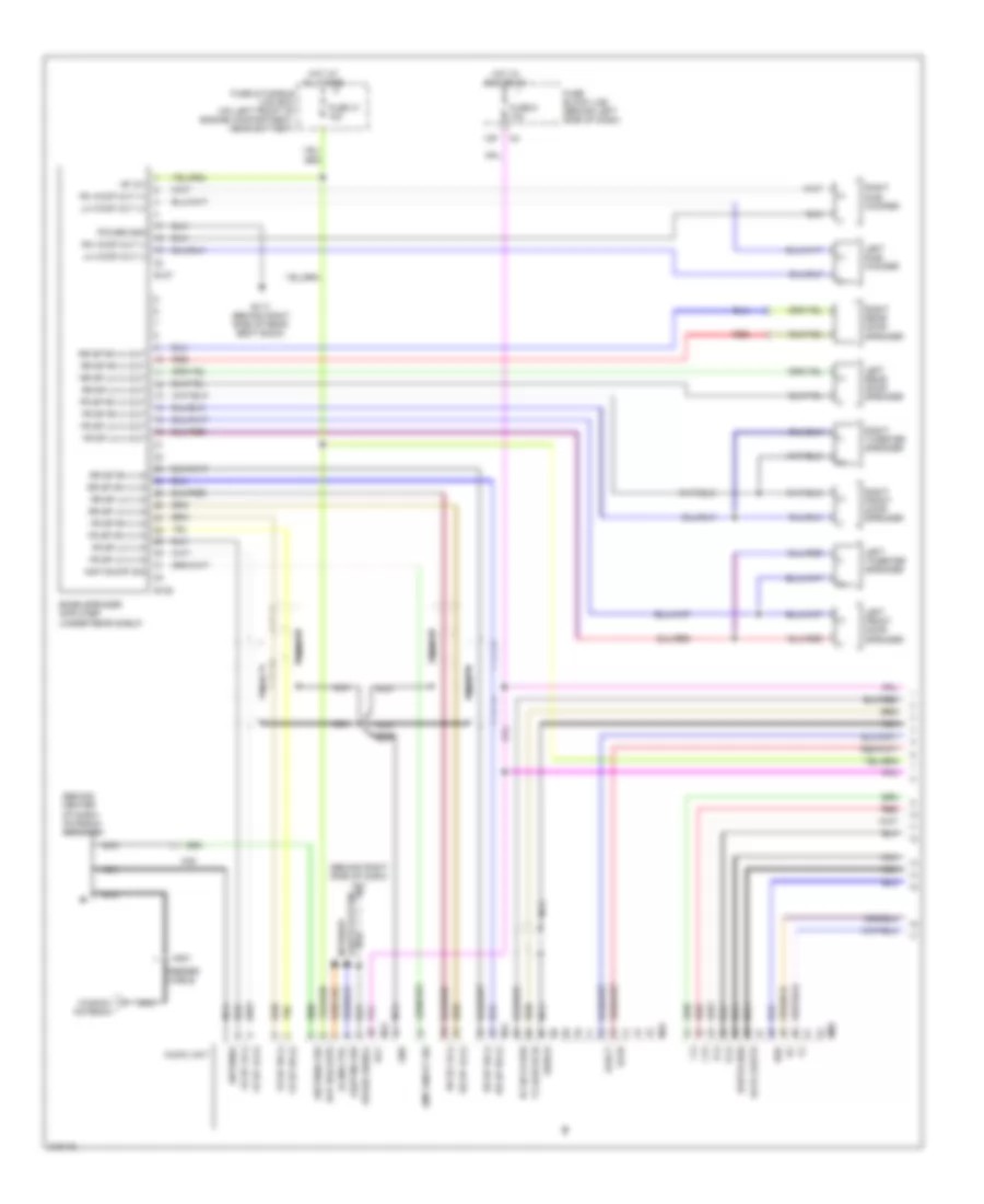
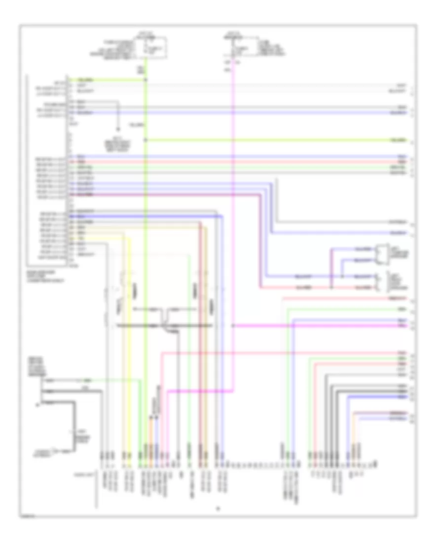
Bose Radio Wiring Diagram, Bose with Navigation (1 of 2) for Nissan Altima SE 2006
List of elements for Bose Radio Wiring Diagram, Bose with Navigation (1 of 2) for Nissan Altima SE 2006:
- (+)
- (-)
- (behind center of dash) antenna amplifier
- (behind right side of dash) m61
- +b 12v
- 12p
- Acc
- Amp on/off sig
- Antenna
- Antenna sig
- Audio unit
- B117 (behind right side of rear seat back)
- B127
- B128
- Bat (backup)
- Bose speaker amplifier (under rear shelf)
- Cable
- Data earth
- Earth (sig)
- Eject
- Feeder
- Fr sp lh (+)
- Fr sp lh (+) in
- Fr sp lh (+) out
- Fr sp lh (-)
- Fr sp lh (-) in
- Fr sp lh (-) out
- Fr sp rh (+)
- Fr sp rh (+) in
- Fr sp rh (+) out
- Fr sp rh (-)
- Fr sp rh (-) in
- Fr sp rh (-) out
- Fuse & fusible link box (on left front of engine compartment, near battery)
- Fuse 31 15a
- Fuse 6 10a
- Fuse block (j/b) (behind left side of dash)
- Gnd
- Hot at all times
- Hot in acc or on
- Illum ctrl
- L (+)
- L (-)
- Left front door speaker
- Left rear door speaker
- Left sub- woofer
- Left tweeter speaker
- Lh woof out (+)
- Lh woof out (-)
- Lighting sw
- Lights system interior
- Load
- M43
- M44
- M45
- M48
- M501
- M80
- Nca
- Power gnd
- R (+)
- R (-)
- Red
- Req
- Rh woof out (+)
- Rh woof out (-)
- Right front door speaker
- Right rear door speaker
- Right sub- woofer
- Right tweeter speaker
- Rr sp lh (+)
- Rr sp lh (+) in
- Rr sp lh (+) out
- Rr sp lh (-)
- Rr sp lh (-) in
- Rr sp lh (-) out
- Rr sp rh (+)
- Rr sp rh (+) in
- Rr sp rh (+) out
- Rr sp rh (-)
- Rr sp rh (-) in
- Rr sp rh (-) out
- Rx (dcu-aud)
- Shield
- Speed signal
- Tx (aud-dcu)
- Window antenna
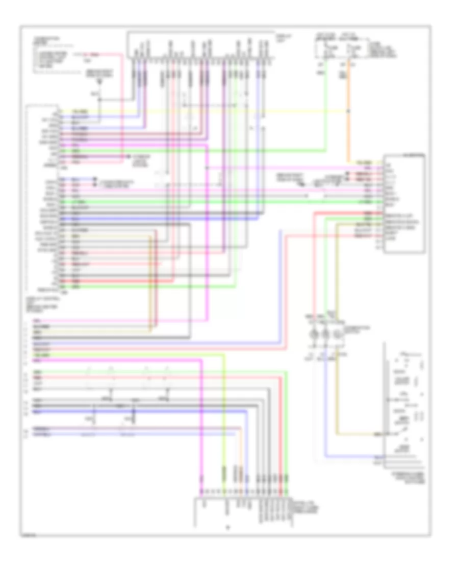
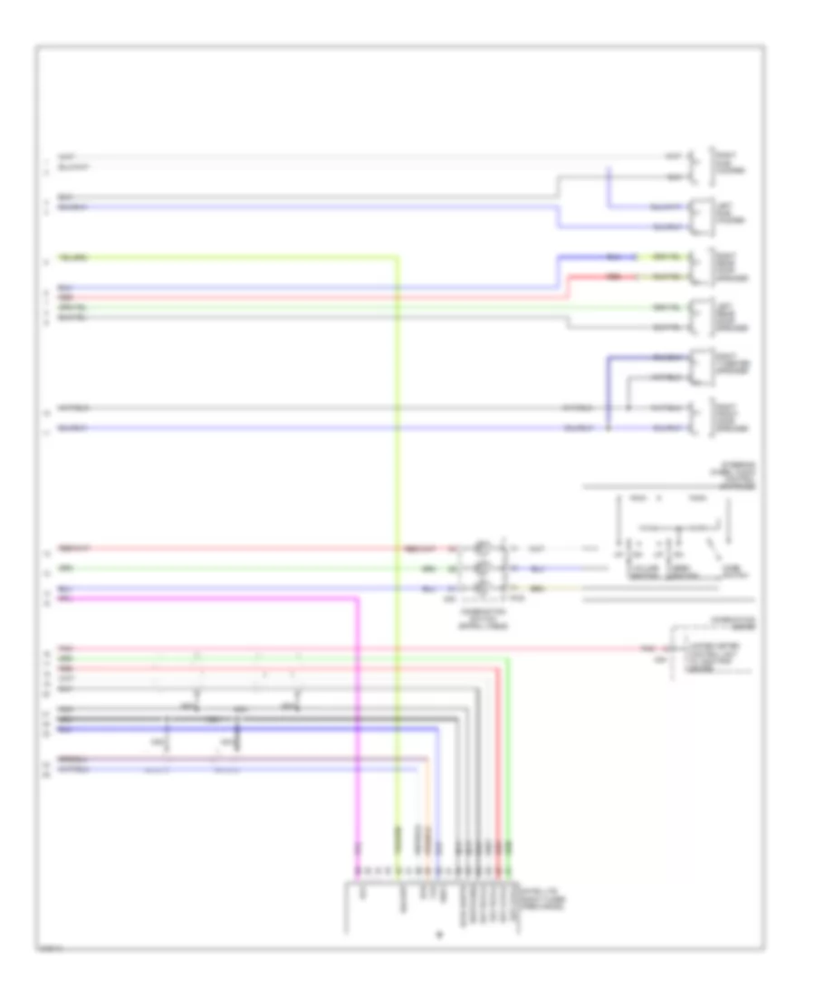
Bose Radio Wiring Diagram, Bose with Navigation (2 of 2) for Nissan Altima SE 2006
List of elements for Bose Radio Wiring Diagram, Bose with Navigation (2 of 2) for Nissan Altima SE 2006:
- (behind right side of dash) m61
- Acc
- Aud 10-dcu
- Av switch
- Backup
- Bus +
- Bus -
- Bus gnd
- Can-h
- Can-l
- Combination meter
- Combination switch
- Computer data lines system
- Data earth
- Dcu-aud 10
- Dcu-dsp
- Display
- Display control unit (behind center of dash)
- Down
- Dsp-dcu
- Earth (sig)
- Eject
- Fuse 10a
- Fuse block (j/b) (behind left side of dash)
- Gnd
- Hot at all times
- Hot in on or start
- Ign
- Ill (+)
- Ill (-)
- Ill +
- Interior lights system
- Inv gnd
- Inv vcc
- Load
- M102
- M24
- M30
- M94
- M95
- Mode switch
- Nca
- Pnk
- Red
- Remote a (up)
- Remote b (down)
- Remote c (gnd)
- Req1
- Rgb gnd
- Rgb sync
- Rxd
- Sat lch (+)
- Sat lch (-)
- Sat rch (+)
- Sat rch (-)
- Satellite radio tuner (pre-wiring)
- Seek switch
- Shield
- Sig vcc
- Sign gnd
- Sign vcc
- Speed
- Steering wheel audio control switches
- Sync gnd
- Txd
- Unified meter control unit (w/ odo/trip meter)
- Unit
- Volume switch
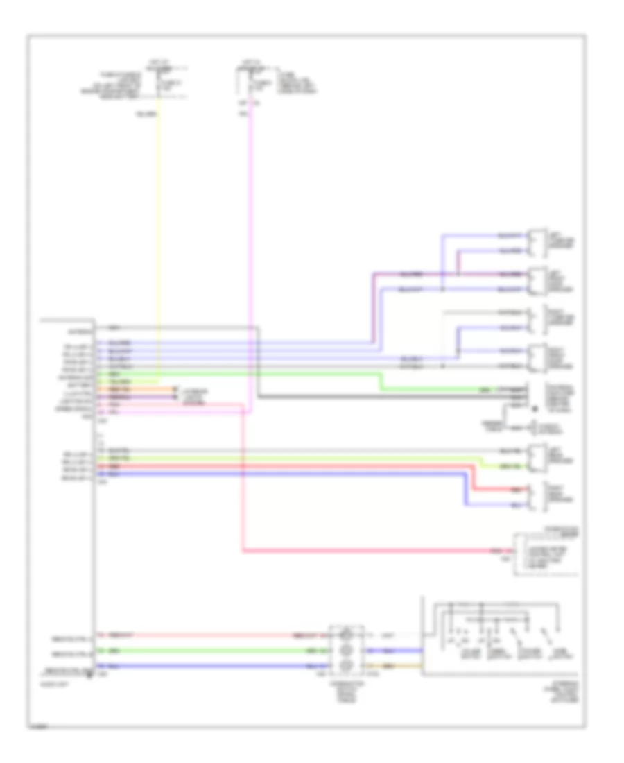
Bose Radio Wiring Diagram, Bose without Navigation (1 of 2) for Nissan Altima SE 2006
List of elements for Bose Radio Wiring Diagram, Bose without Navigation (1 of 2) for Nissan Altima SE 2006:
- (+)
- (-)
- (behind center of dash) antenna amplifier
- +b 12v
- 12p
- Acc
- Amp on/off sig
- Antenna
- Antenna sig
- Audio unit
- B117 (behind right side of rear seat back)
- B127
- B128
- Bat (backup)
- Bose speaker amplifier (under rear shelf)
- Cable
- Data earth
- Earth (sig)
- Feeder
- Fr sp lh (+)
- Fr sp lh (+) in
- Fr sp lh (+) out
- Fr sp lh (-)
- Fr sp lh (-) in
- Fr sp lh (-) out
- Fr sp rh (+)
- Fr sp rh (+) in
- Fr sp rh (+) out
- Fr sp rh (-)
- Fr sp rh (-) in
- Fr sp rh (-) out
- Fuse & fusible link box (on left front of engine compartment, near battery)
- Fuse 31 15a
- Fuse 6 10a
- Fuse block (j/b) (behind left side of dash)
- Gnd
- Hot at all times
- Hot in acc or on
- Illum ctrl
- L (+)
- L (-)
- Left front door speaker
- Left tweeter speaker
- Lh woof out (+)
- Lh woof out (-)
- Lighting sw
- Lights system interior
- M43
- M44
- M45
- M48
- M501
- M80
- Nca
- Pnk
- Power gnd
- R (+)
- R (-)
- Red
- Remote ctrl a
- Remote ctrl b
- Remote ctrl gnd
- Req
- Rh woof out (+)
- Rh woof out (-)
- Rr sp lh (+)
- Rr sp lh (+) in
- Rr sp lh (+) out
- Rr sp lh (-)
- Rr sp lh (-) in
- Rr sp lh (-) out
- Rr sp rh (+)
- Rr sp rh (+) in
- Rr sp rh (+) out
- Rr sp rh (-)
- Rr sp rh (-) in
- Rr sp rh (-) out
- Speed signal
- Window antenna
Bose Radio Wiring Diagram, Bose without Navigation (2 of 2) for Nissan Altima SE 2006
List of elements for Bose Radio Wiring Diagram, Bose without Navigation (2 of 2) for Nissan Altima SE 2006:
- (+)
- (-)
- Acc
- Backup
- Combination meter
- Combination switch (spiral cable)
- Data earth
- Earth (sig)
- Left rear door speaker
- Left sub- woofer
- M102
- M24
- M30
- Mode switch
- Nca
- Pnk
- Red
- Req1
- Right front door speaker
- Right rear door speaker
- Right sub- woofer
- Right tweeter speaker
- Rxd
- Sat lch (+)
- Sat lch (-)
- Sat rch (+)
- Sat rch (-)
- Satellite radio tuner (pre-wiring)
- Seek switch
- Steering wheel audio control switches
- Txd
- Unified meter control unit (w/ odo/trip meter)
- Volume switch
Mid-Line Radio Wiring Diagram for Nissan Altima SE 2006
List of elements for Mid-Line Radio Wiring Diagram for Nissan Altima SE 2006:
- (+)
- (-)
- 12p
- Acc
- Antenna
- Antenna amplifier (behind center of dash)
- Antenna sig
- Audio unit
- Battery
- Combination meter
- Combination switch (spiral cable)
- Feeder cable
- Fr lh sp (+)
- Fr lh sp (-)
- Fr rh sp (+)
- Fr rh sp (-)
- Fuse & fusible link box (on left front of engine compartment, near battery)
- Fuse 31 15a
- Fuse 6 10a
- Fuse block (j/b) (behind left side of dash)
- Hot at all times
- Hot in acc or on
- Illum ctrl
- Interior lights system
- Left front door speaker
- Left rear speaker
- Left tweeter speaker
- Lighting sw
- M102
- M24
- M30
- M43
- M44
- M45
- Mode switch
- Nca
- Pnk
- Power switch
- Red
- Remote ctrl a
- Remote ctrl b
- Remote ctrl gnd
- Right front door speaker
- Right rear speaker
- Right tweeter speaker
- Rr lh sp (+)
- Rr lh sp (-)
- Rr rh sp (+)
- Rr rh sp (-)
- Seek switch
- Speed signal
- Steering wheel audio control switches
- Unified meter control unit (w/ odo/trip meter)
- Volume switch
- Window antenna
SHIFT INTERLOCK
Shift Interlock Wiring Diagram for Nissan Altima SE 2006
List of elements for Shift Interlock Wiring Diagram for Nissan Altima SE 2006:
- (behind right side of dash) m57
- A/t device (beneath gear selector lever assembly)
- Bat
- Combination meter
- Detent sw
- Detent sw(shift) stop lamp sw
- Detent switch key
- Detent switch shift
- E30
- Fuse 10a
- Fuse block (j/b) (behind left side of dash)
- Gnd
- Hot at all times
- Hot in on or start
- Ign sw
- Key lock sol out
- Key lock solenoid
- Key switch & key lock solenoid (on right side of steering column)
- Lock sol out
- M24
- Nca
- Pnk
- Shift lock control unit (behind upper left side of dash)
- Shift lock sol out
- Shift lock solenoid
- Stop lamp switch (above brake pedal, on bracket)
- Vsp sig
STARTING/CHARGING
Charging Wiring Diagram for Nissan Altima SE 2006
List of elements for Charging Wiring Diagram for Nissan Altima SE 2006:
- Battery
- Charge indicator
- Combination meter
- E e112
- E116 (at right front corner of engine compartment)
- F40
- Fuse & fusible link box (on left front of engine compartment, near battery)
- Fuse 10a
- Fuse 26 10a
- Fuse block (j/b) (behind left side of dash)
- Fusible link a 120a
- Fusible link box (battery) (on left front of engine compt, near battery)
- Generator
- Hot at all times
- Hot in on or start
- L f1
- M24
- Nca
- Starter motor
- Unified meter control unit
Starting Wiring Diagram, A/T for Nissan Altima SE 2006
List of elements for Starting Wiring Diagram, A/T for Nissan Altima SE 2006:
- (4 speed)
- (4 speed) (5 speed)
- (5 speed)
- Acc on
- Battery
- Body control module (bcm) (behind left side of dash)
- Can-h
- Can-l
- Cpu
- E119
- E121
- E124
- E24 (at right side of engine compartment)
- E30
- Fuse & fusible link box (on left front of of engine compt, near battery)
- Fuse 10a
- Fuse block (j/b) (behind left side of dash)
- Fusible link m 40a
- Hot at all times
- Hot in on or start
- Ignition switch
- Ipdm e/r (intelligent power distribution module engine room) (on right front of engine compt, behind headlight)
- M18
- Nca
- Off
- Park/ neutral position (pnp) switch
- Pnk
- Start
- Starter motor
- Starter relay
Starting Wiring Diagram, M/T for Nissan Altima SE 2006
List of elements for Starting Wiring Diagram, M/T for Nissan Altima SE 2006:
- 1q e30
- Acc
- Battery
- Body control module (bcm) (behind left side of dash)
- Can-h
- Can-l
- Clutch interlock switch (above clutch pedal, on bracket)
- Computer data lines system
- Cpu
- E119
- E121
- E124
- E15 (at left side of engine compt, near battery)
- E24 (at right side of engine compt)
- Fuse & fusible link box (on left front of engine compartment, near battery)
- Fuse 10a
- Fuse block (j/b) (behind left side of dash)
- Fusible link m 40a
- Hot at all times
- Hot in on or start
- Ignition switch
- Ipdm e/r (intelligent power distribution module engine room) (on right front of engine compartment, behind headlight)
- M18
- Nca
- Off
- Pnk
- Start
- Starter motor
- Starter relay
SUPPLEMENTAL RESTRAINTS
Supplemental Restraints Wiring Diagram (1 of 3) for Nissan Altima SE 2006
List of elements for Supplemental Restraints Wiring Diagram (1 of 3) for Nissan Altima SE 2006:
- (behind right side of dash) m57
- (behind right side of dash) m61
- Air bag diagnosis sensor unit (below center console, between seats)
- Air bag w/l
- Airbag ind
- As1 (+)
- As1 (-)
- As2 (+)
- As2 (-)
- B113
- Buckle sw input
- C-lh1 (+)
- C-lh1 (-)
- C-rh1 (+)
- C-rh1 (-)
- Combination meter
- Cut off telltale
- Data link connector (partial) (below left side of dash)
- Dr1 (+)
- Dr1/dr2 (-)
- Dr2 (+)
- Eczs (+)
- Eczs (-)
- Fuse 10a
- Fuse block (j/b) (behind left side of dash)
- Gnd
- Hot in on or start
- Ign
- K-line
- Left front air bag (satellite) sensor (if equipped) (under left front seat)
- Left sat (+)
- Left sat (-)
- Left side curtain air bag module (if equipped) (at left "c" pillar)
- M24
- M35
- Nca
- Ods inp
- P-lh1 (+)
- P-lh1 (-)
- P-rh1 (+)
- P-rh1 (-)
- R-sat (+)
- R-sat (-)
- Right front air bag (satellite) sensor (if equipped) (under right front seat)
- Right front seat belt pretensioner (on right "b" pillar)
- Right front side air bag module (if equipped) (under right front seat)
- Right side curtain air bag module (if equipped) (at right "c" pillar)
- S-lh1 (+)
- S-lh1 (-)
- S-rh1 (+)
- S-rh1 (-)
- Seat belt
- Seat belt reminder
- Seat buckle sw
- Unified meter control unit
Supplemental Restraints Wiring Diagram (2 of 3) for Nissan Altima SE 2006
List of elements for Supplemental Restraints Wiring Diagram (2 of 3) for Nissan Altima SE 2006:
- (at left side of engine compartment, near battery) e14
- (behind left side of rear seat back) b19
- (behind right side of rear seat back) b117
- (service replacement) front passenger air bag module
- Combination switch (spiral cable)
- Crash zone sensor (behind front center of grille, near hood latch)
- Driver air bag module
- Fastened
- Front passenger air bag module
- Left front seat belt pretensioner (on left "b" pillar)
- Left front side air bag module (if equipped) (under left front seat)
- Left seat belt buckle switch (inside left front seat belt buckle)
- M101
- M103
- M77
- M78
- Nca
- Red
- Right seat belt buckle switch (inside right front seat belt buckle)
- Un- fastened
- W/o service replacement
- W/service replacement
Supplemental Restraints Wiring Diagram (3 of 3) for Nissan Altima SE 2006
List of elements for Supplemental Restraints Wiring Diagram (3 of 3) for Nissan Altima SE 2006:
- (+)
- (-)
- B117 (behind right side of rear seat back)
- Belt tension sensor
- Bts (+)
- Bts (-)
- Bts sig
- Front passenger air bag off indicator
- Gnd
- Ign
- M61 (behind right side of dash)
- Occupant classification system control unit
- Occupant classification system sensor
- Ods led
- Pass air bag off ind
- Red
- Sig
TRANSMISSION
A/T Wiring Diagram, 4 Speed A/T for Nissan Altima SE 2006
List of elements for A/T Wiring Diagram, 4 Speed A/T for Nissan Altima SE 2006:
- (left rear of transaxle) park/neutral position switch
- (left side of engine compt) dropping resistor
- 1 pos
- 2 pos
- 3 pos
- A/t check
- A/t device (3rd position switch)
- A/t fluid temp sensor
- Automatic transaxle
- Avcc
- Avcc2
- Can h
- Can l
- Can-h
- Can-l
- Combination meter
- Computer data lines system
- D pos
- Data link connector (below left side of dash)
- Duty sol
- Ect
- Electronic throttle control actuator (integral with throttle body)
- Engine control module (ecm) (behind glove box)
- Engine controls system
- Engine coolant temperature sensor (left rear of engine)
- Exterior lights system
- F14 (front of engine)
- Fuse 10a
- Fuse block (behind left side of dash)
- Gnd
- Gnd sens
- Gnd-a
- Hot at all times
- Hot in on or start
- Ign
- Intelligent power distribution module engine room (ipdm e/r)
- Line press sol valve
- Lu duty
- M57 (behind right side of dash)
- Mem b/u
- N pos
- Nca
- Oil temp
- Over- run clutch sol
- Ovr/c
- P pos
- P/n out
- P/n pos
- P/t sens
- Pnk
- R pos
- Red
- Revolution sensor (right rear of transaxle)
- Shift sol valve a
- Shift sol valve b
- Sp sens
- Ssa
- Ssb
- Starting/ charging system
- Tacho
- Tcc sol valve
- Tps 1
- Tps 2
- Transmission control module (tcm) (behind right side of dash)
- Turbine revolution sensor (right rear of transaxle)
- Tv01
- Tvoo
- V sens
- Vehicle speed sensor (right front of transaxle)
- Vig
- Vss in
- Vss out
A/T Wiring Diagram, 5 Speed A/T for Nissan Altima SE 2006
List of elements for A/T Wiring Diagram, 5 Speed A/T for Nissan Altima SE 2006:
- (behind glove box) ecm
- (on front of engine) f14
- (on left rear of transaxle) park/neutral position switch
- A/t device (manual mode switch)
- A/t fluid temp sensor
- A/t pv ign relay
- Auto
- Automatic transaxle
- Can-h
- Can-l
- Combination meter
- Computer data lines system
- Dwn
- F14 (on front of engine)
- F30
- F62
- Fuse 10a
- Fuse block (behind left side of dash)
- Gnd
- Hot at all times
- Hot in on or start
- Ig1
- Ig2
- Igr5
- Ipdm e/r (on right front of engine compt, behind headlight)
- M61 (behind right side of dash)
- Man
- Nc+
- Nc-
- Nca
- Otg
- Red
- Revolution sensor (right rear of transaxle)
- Sens gnd
- Shift sol valve a
- Shift sol valve b
- Shift sol valve c
- Shift sol valve d
- Shift sol valve e
- Sls
- Slsg
- Slt
- Sltg
- Slu
- Slug
- Sol a
- Sol b
- Sol c
- Sol d
- Sol e
- Starting/ charging system
- Tcm (behind right side of dash)
- Turbine revolution sensor (right rear of transaxle)
- Vss 1
TRUNK, TAILGATE, FUEL DOOR
Trunk Release Wiring Diagram for Nissan Altima SE 2006
List of elements for Trunk Release Wiring Diagram for Nissan Altima SE 2006:
- B7 (on left ``b" pillar)
- Bat
- Body control module (behind left side of dash)
- Fuse & fusible link box (on left front of engine compartment, near battery)
- Fusible link f 50a
- Hot at all times
- M18
- M20
- M57 (behind right side of dash)
- Pnk
- Trunk lamp switch & trunk release solenoid (on rear center of trunk lid)
- Trunk lid opener cancel switch
- Trunk lid opener switch
- Trunk opener out m19
- Trunk sw
- W/ trunk lid opener cancel switch
- W/o trunk lid opener cancel switch
WARNING SYSTEMS
Warning Systems Wiring Diagram for Nissan Altima SE 2006
List of elements for Warning Systems Wiring Diagram for Nissan Altima SE 2006:
- (behind right side of dash) m57
- 12p
- Acc
- Air bag diagnosis sensor unit (below center console, between seats)
- B7 (on left "b" pillar)
- Bat
- Body control module (bcm) (behind left side of dash)
- Buckle sw
- Buzzer
- Can-h
- Can-l
- Combination meter
- Combination switch (lighting switch, front fog lamp switch)
- Computer data lines system
- Door ind
- Fuse & fusible link box (on left front of engine compartment, near battery)
- Fuse 10a
- Fuse block (j/b) (behind left side of dash)
- Fusible link f 50a
- Gnd
- Hot at all times
- Hot in acc or on
- Hot in on or start
- Input 1
- Input 2
- Input 3
- Input 4
- Input 5
- Key sw
- Key switch & keylock solenoid (on right side of steering column)
- Left front door switch (at left front door sill)
- Left seat belt buckle switch (inside left front seat belt buckle)
- Lf door sw
- M18
- M19
- M20
- M35
- Output 1
- Output 2
- Output 3
- Output 4
- Output 5
- Pnk
- Seat belt
- Seat belt ind
- Unified meter control unit (w/odo/trip meter)
WIPER/WASHER
Wiper/Washer Wiring Diagram for Nissan Altima SE 2006
List of elements for Wiper/Washer Wiring Diagram for Nissan Altima SE 2006:
- 15p
- Bat
- Body control module (bcm) (behind left side of dash)
- Can-h
- Can-l
- Combination meter
- Combination switch (front wiper switch)
- Computer data lines system
- Cpu
- E121
- E122
- E124
- E15 (at left side of engine compt, near battery)
- E24 (at right side of engine compt)
- Fr washer motor
- Front washer motor (on washer fluid reservoir)
- Front wiper hi relay
- Front wiper motor (on left side of firewall)
- Front wiper relay
- Fuse & fusible link box (on left front of engine compt, near battery)
- Fuse 10a
- Fuse 15a
- Fuse 20a
- Fuse block (j/b) (behind left side of dash)
- Fusible link f 50a
- Gnd
- High
- Hot at all times
- Hot in on or start
- Ign
- Ignition relay
- Input 1
- Input 2
- Input 3
- Input 4
- Input 5
- Intput 1
- Intput 2
- Intput 3
- Intput 4
- Intput 5
- Ipdm e/r (intelligent power distribution module engine room) (on right front of engine compartment, behind headlight)
- Low
- M18
- M20
- M24
- M28
- M57 (behind right side of dash)
- Move
- Output 1
- Output 2
- Output 3
- Output 4
- Output 5
- Pnk
- Red
- Stop
- Washer fluid level sensor (on washer fluid reservoir)
- Washer ind

 Čeština
 Dansk
Dansk Deutsch
 Ελληνικά
 English
 English
 Español
 Suomi
Suomi Français
 Français
 עברית
עברית Hrvatski
 Magyar
 Italiano
 日本語
日本語 한국어
한국어 Nederlands
 Polski
 Português
 Português
 Română
 Русский
 Slovenčina
 Slovenščina
 Türkçe
 中文 (中国)