AIR CONDITIONING
1.8L VIN 8
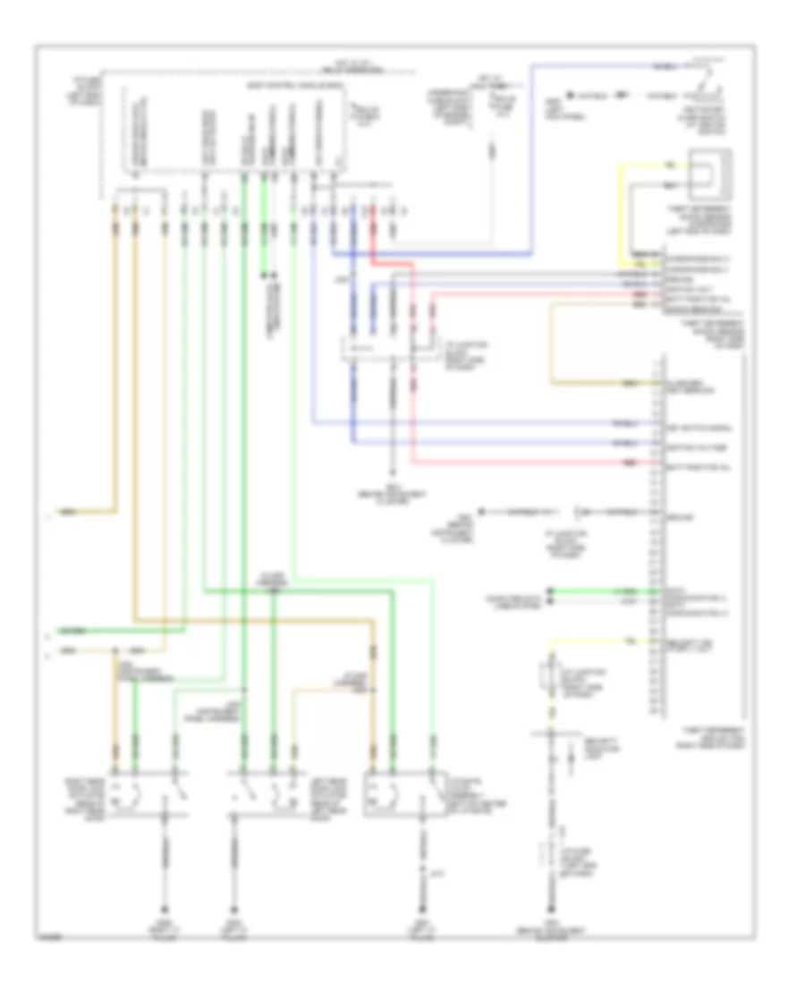
1.8L VIN 8, Compressor Wiring Diagram for Pontiac Vibe 2010
 https://portal-diagnostov.com/license.html
Automotive Electricians Portal FZCO
Automotive Electricians Portal FZCO
https://portal-diagnostov.com/license.html
https://portal-diagnostov.com/license.html
Automotive Electricians Portal FZCO
Automotive Electricians Portal FZCO
List of elements for 1.8L VIN 8, Compressor Wiring Diagram for Pontiac Vibe 2010:
- (behind instrument cluster) g201
- 5 volt ref
- A/c compressor clutch (left front of engine)
- A/c compressor clutch ctrl
- A/c refrigerant press sens sig
- A/c refrigerant pressure sensor
- Batt positive vol
- Computer data lines system
- Ecu-b2 fuse 10a
- Evaporator temp sens sig
- Evaporator temperature sensor (bottom of hvac)
- G104 (1.8l: top of engine) (2.4l: left rear of engine)
- Ground
- Hi sp gm lan
- Hi sp gm lan serial data bus-
- Hot at all times
- Hvac control module (center of dash)
- I/p fuse block (left end of dash)
- J205
- Low ref
- Serial data bus+
- Underhood fuse block (left side of engine compt)
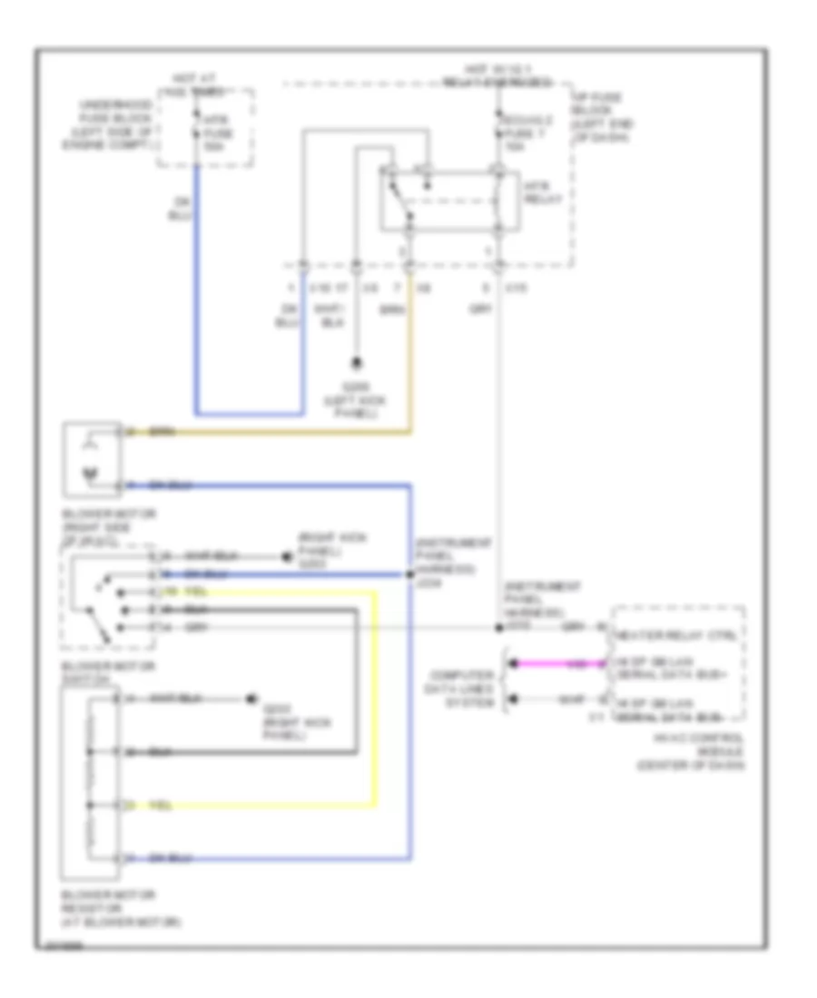
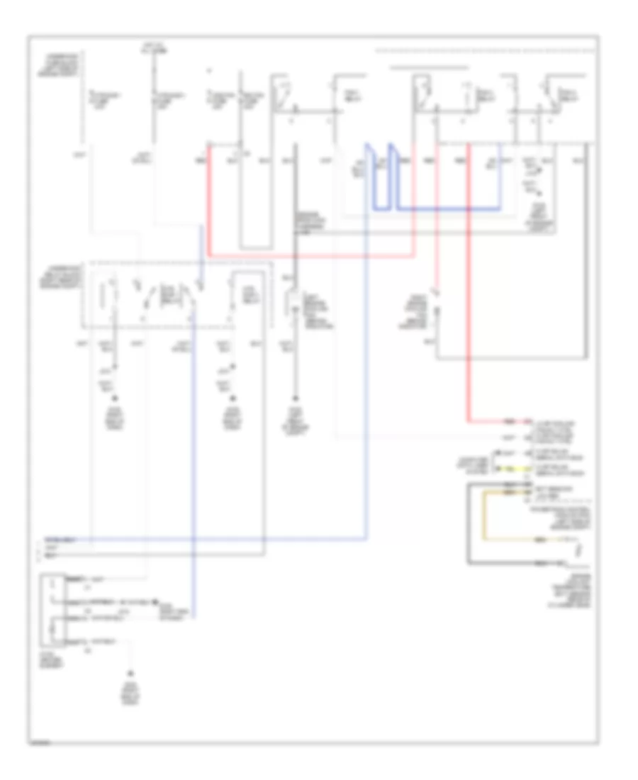
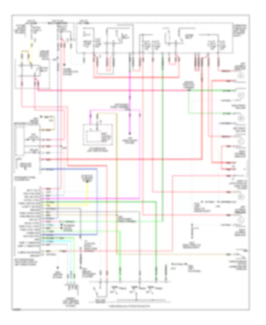
1.8L VIN 8, Heater Wiring Diagram for Pontiac Vibe 2010
List of elements for 1.8L VIN 8, Heater Wiring Diagram for Pontiac Vibe 2010:
- (instrument panel harness) j212
- (instrument panel harness) j234
- (right kick panel) g203
- Blower motor (right side of hvac)
- Blower motor resistor (at blower motor)
- Blower motor switch
- Computer data lines system
- Ecu-ig 2 fuse 7 10a
- G200 (left kick panel)
- G203 (right kick panel)
- Heater relay ctrl
- Hi sp gm lan
- Hi sp gm lan serial data bus- x1
- Hot at all times
- Hot w/ ig 1 relay energized
- Htr fuse 50a
- Htr relay
- Hvac control module (center of dash)
- I/p fuse block (left end of dash)
- Serial data bus+
- Underhood fuse block (left side of engine compt)
- X10
- X15
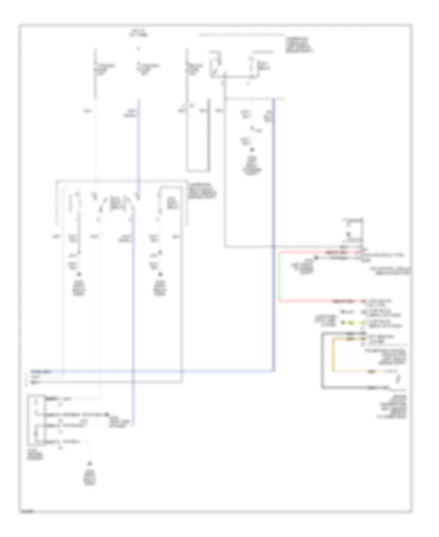
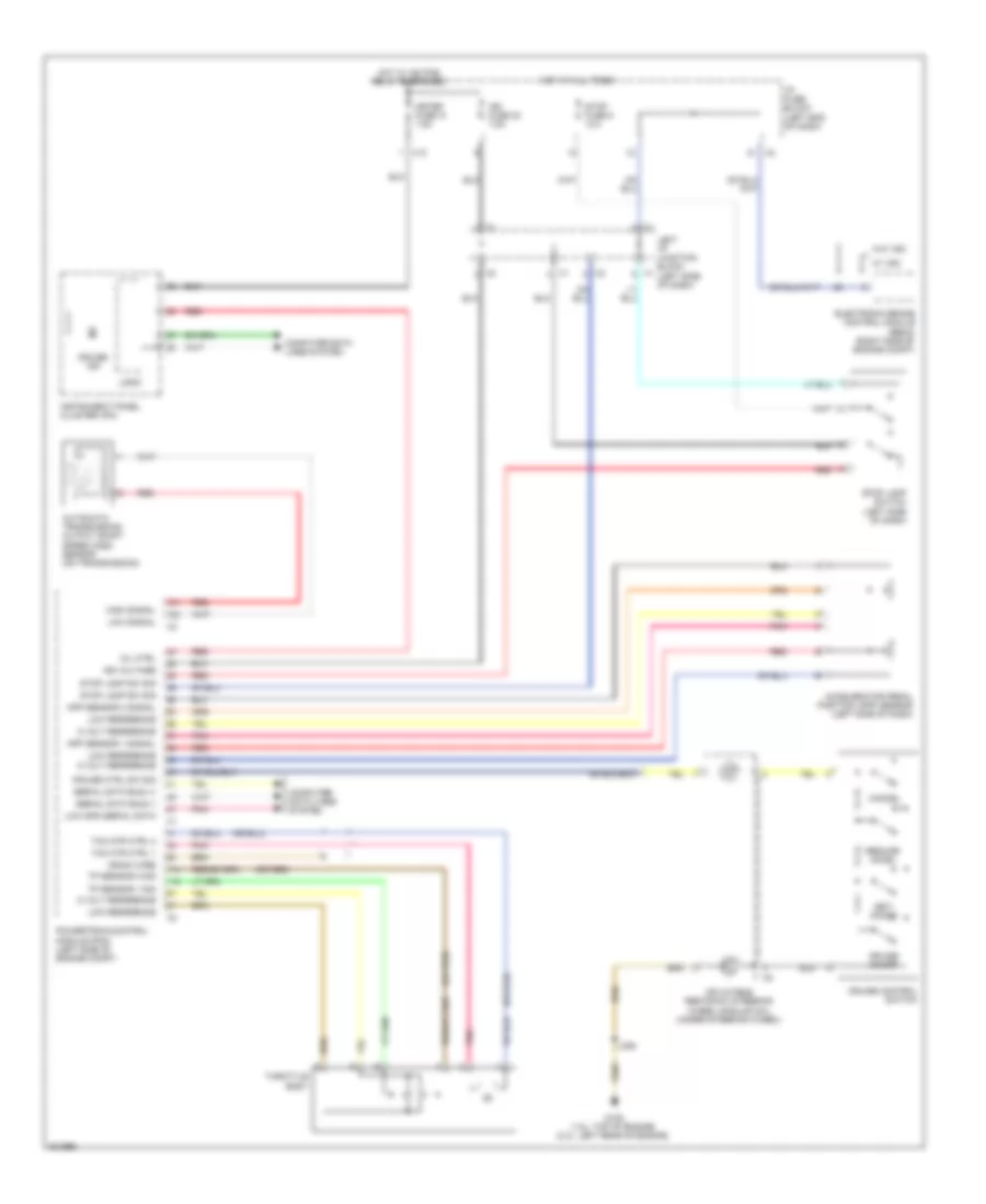
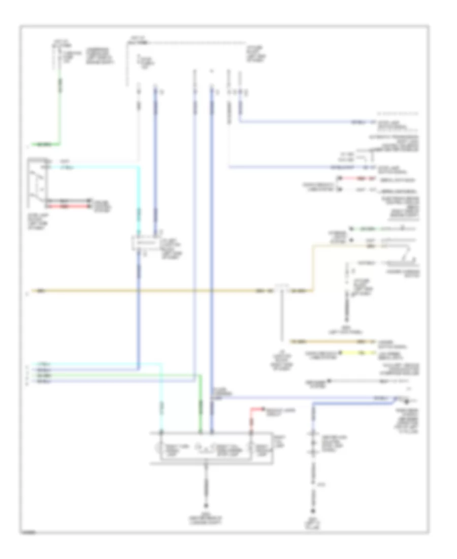
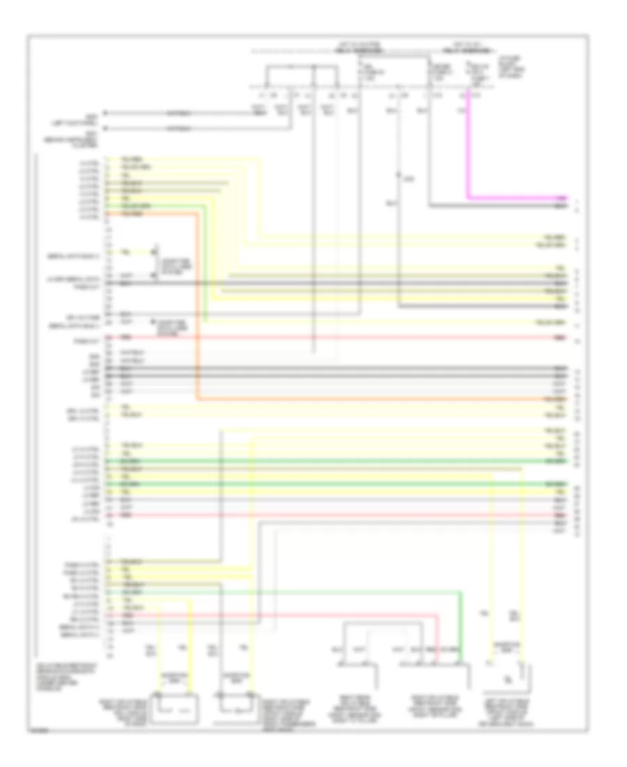
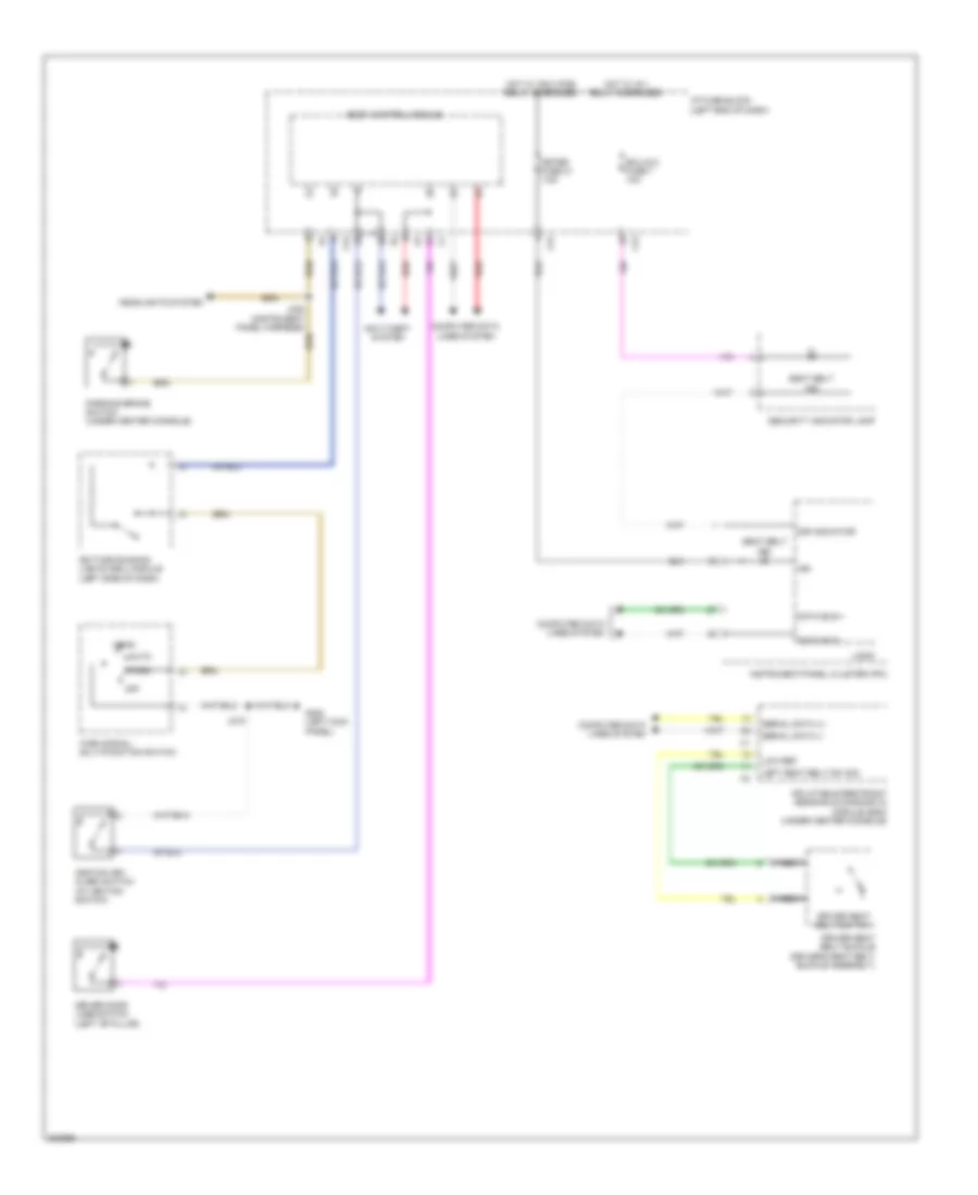
1.8L VIN 8, Manual A/C Wiring Diagram (1 of 2) for Pontiac Vibe 2010
List of elements for 1.8L VIN 8, Manual A/C Wiring Diagram (1 of 2) for Pontiac Vibe 2010:
- (behind instrument cluster) g201
- (instrument panel harness) j212
- (instrument panel harness) j216
- (instrument panel harness) j234
- (right front of engine compt) a/c refrigerant pressure sensor
- (right kick panel) g203
- 5 volt ref
- A/c compressor clutch (left front of engine)
- A/c compressor clutch ctrl
- A/c refrigerant press sens sig
- A/c request sig
- A/c switch
- Batt positive vol
- Blower motor (right side of hvac)
- Blower motor resistor (at blower motor)
- Blower motor switch
- Computer data lines system
- Dimming sig
- Ecu-b2 fuse 10a
- Ecu-ig 1 fuse 10a
- Ecu-ig 2 fuse 7 10a
- Evaporator temp sens sig
- Evaporator temperature sensor (bottom of hvac)
- G104 (top of engine)
- G200 (left kick panel)
- G201 (behind instrument cluster)
- G203 (right kick panel)
- Generator turn on sig
- Ground
- Headlamp rly ctrl
- Headlights system starting/ charging system
- Heated mirror switch
- Heater relay ctrl
- Hi sp gm lan serial data bus+
- Hi sp gm lan serial data bus-
- Hot at all times
- Hot w/ ig 1 relay energized
- Htr fuse 50a
- Htr relay
- Htr request sig
- Htr sub 1 rly ctrl
- Htr sub 3 rly ctrl
- Htr-ig 2 fuse 2 10a
- Hvac control module (center of dash)
- Hvac mode switch
- Hvac temperature switch
- I/p fuse block (left end of dash)
- Ign volt
- J115
- J205
- J214
- Left i/p junction block (left side of dash)
- Low ref
- Pnk
- Recirculating switch
- Recirculation actuator (top center of hvac)
- Red
- Underhood fuse block (left side of engine compt)
- Windshield defrost switch
- X10
- X15
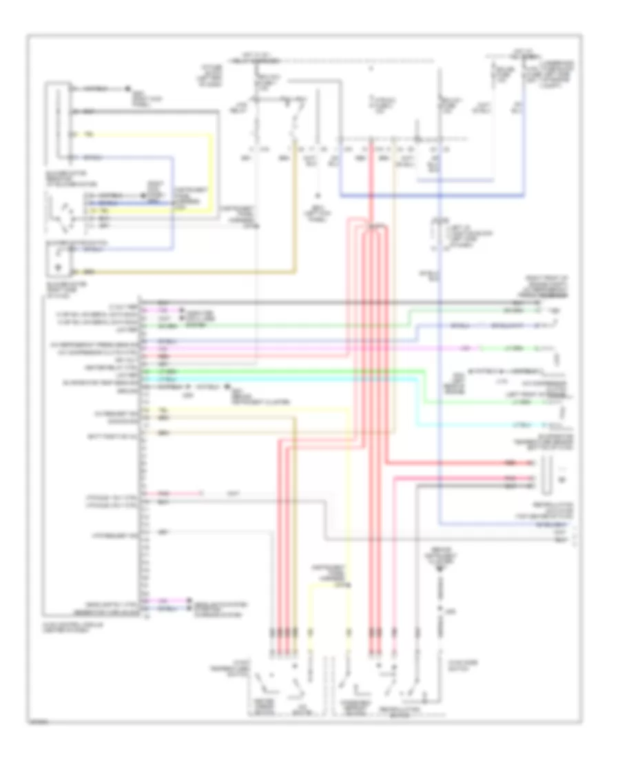
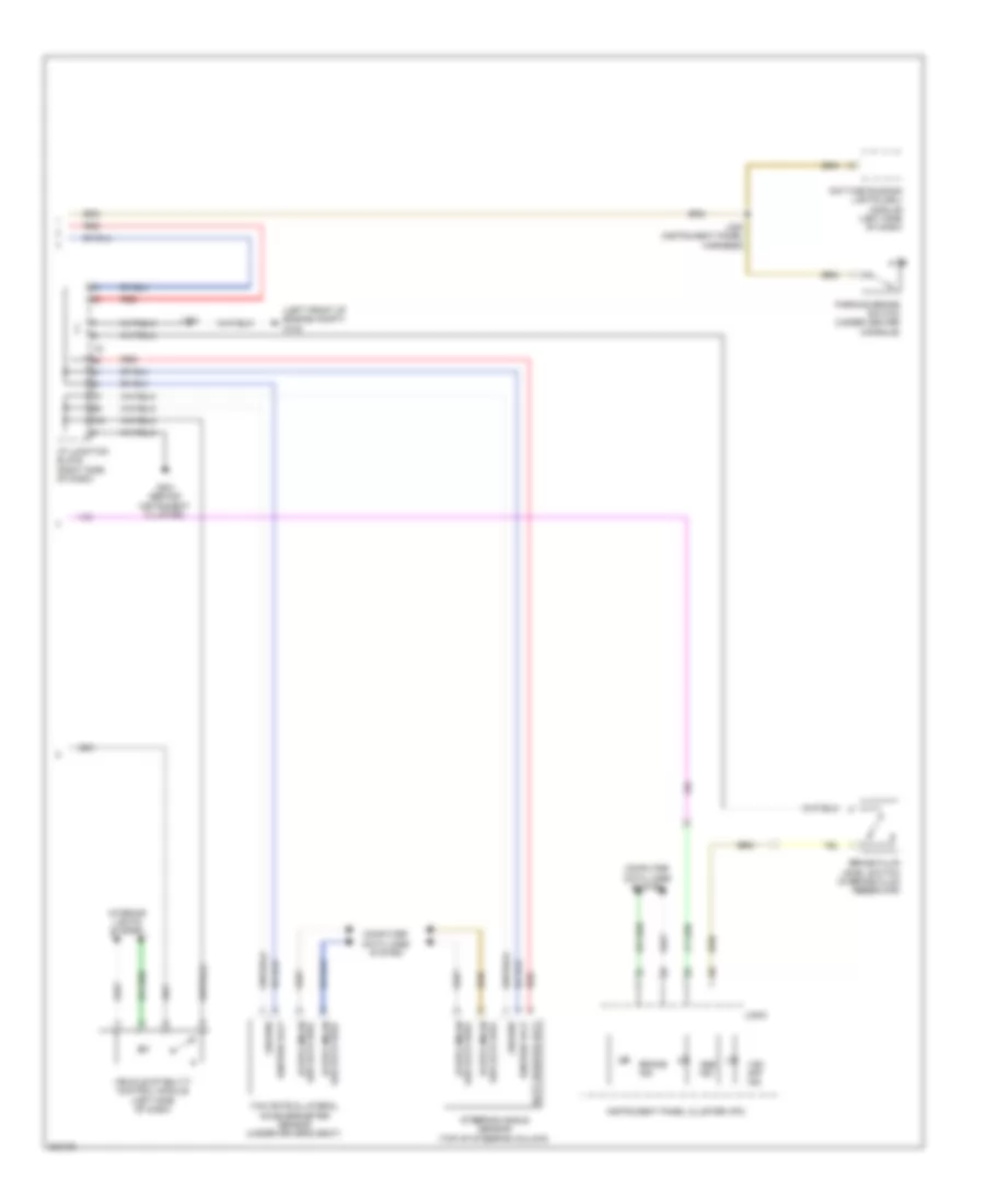
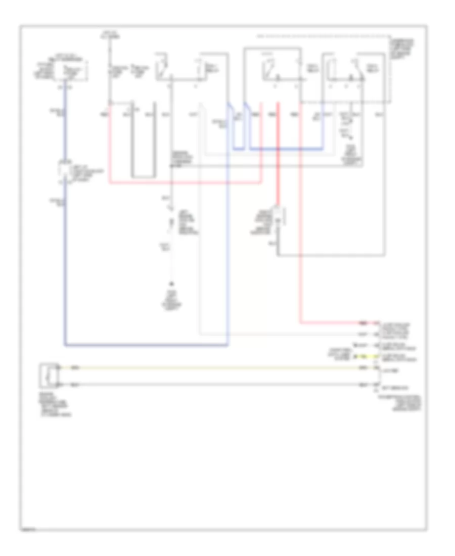
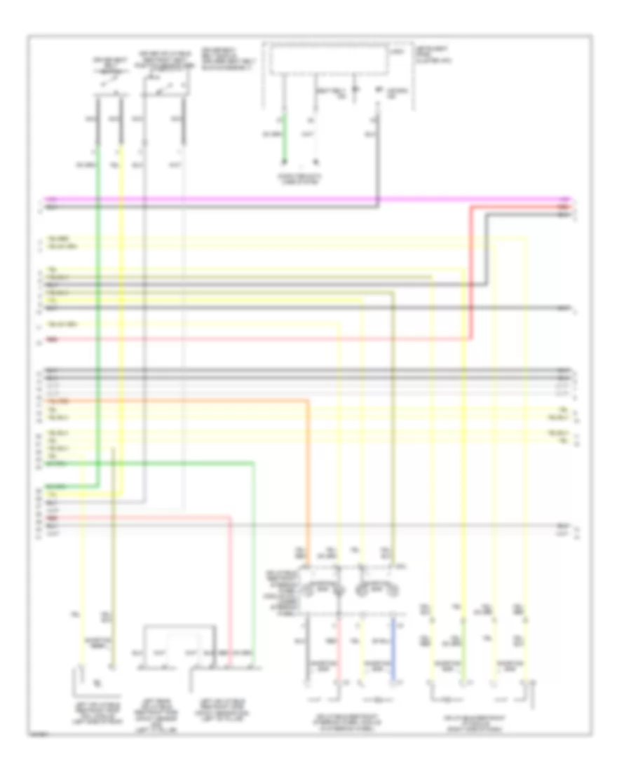
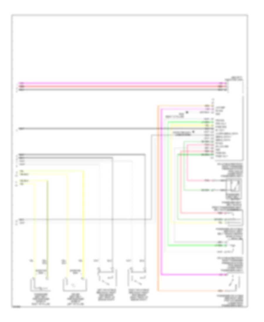
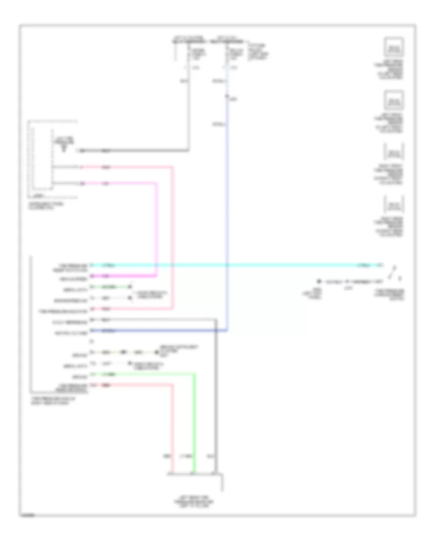
1.8L VIN 8, Manual A/C Wiring Diagram (2 of 2) for Pontiac Vibe 2010
List of elements for 1.8L VIN 8, Manual A/C Wiring Diagram (2 of 2) for Pontiac Vibe 2010:
- Computer data lines system
- Cooling fan
- Cooling fan rly ctrl
- Ect sens sig
- Engine coolant temperature (ect) sensor (rear of cylinder head)
- Fan 1 relay
- Fan control module (behind radiator)
- G102 (left front of engine compt)
- G108 (right end of dash)
- Gnd
- Hi sp gmlan
- Hot at all times
- Htr sub 1 fuse 30a
- Htr sub 1 relay
- Htr sub 3 fuse 30a
- Htr sub 3 relay
- Hvac heater element
- J104
- J213
- Low ref
- Nca
- Powertrain control module (pcm) (left side of engine compt)
- Rdi fan fuse 40a
- Rly ctrl
- Serial data bus+
- Serial data bus-
- Underhood fuse block (left side of engine compt)
- Underhood relay block (right rear of engine compt)
2.4L VIN 0
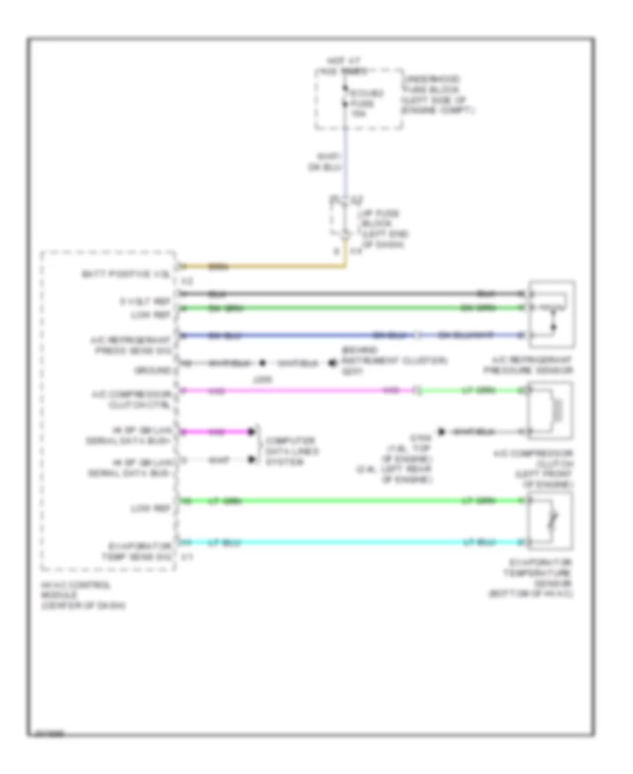
2.4L VIN 0, Compressor Wiring Diagram for Pontiac Vibe 2010
List of elements for 2.4L VIN 0, Compressor Wiring Diagram for Pontiac Vibe 2010:
- (behind instrument cluster) g201
- 5 volt ref
- A/c compressor clutch (left front of engine)
- A/c compressor clutch ctrl
- A/c refrigerant press sens sig
- A/c refrigerant pressure sensor
- Batt positive vol
- Computer data lines system
- Ecu-b2 fuse 10a
- Evaporator temp sens sig
- Evaporator temperature sensor (bottom of hvac)
- G104 (1.8l: top of engine) (2.4l: left rear of engine)
- Ground
- Hi sp gm lan
- Hi sp gm lan serial data bus-
- Hot at all times
- Hvac control module (center of dash)
- I/p fuse block (left end of dash)
- J205
- Low ref
- Serial data bus+
- Underhood fuse block (left side of engine compt)
2.4L VIN 0, Heater Wiring Diagram for Pontiac Vibe 2010
List of elements for 2.4L VIN 0, Heater Wiring Diagram for Pontiac Vibe 2010:
- (instrument panel harness) j212
- (instrument panel harness) j234
- (right kick panel) g203
- Blower motor (right side of hvac)
- Blower motor resistor (at blower motor)
- Blower motor switch
- Computer data lines system
- Ecu-ig 2 fuse 7 10a
- G200 (left kick panel)
- G203 (right kick panel)
- Heater relay ctrl
- Hi sp gm lan
- Hi sp gm lan serial data bus- x1
- Hot at all times
- Hot w/ ig 1 relay energized
- Htr fuse 50a
- Htr relay
- Hvac control module (center of dash)
- I/p fuse block (left end of dash)
- Serial data bus+
- Underhood fuse block (left side of engine compt)
- X10
- X15
2.4L VIN 0, Manual A/C Wiring Diagram (1 of 2) for Pontiac Vibe 2010
List of elements for 2.4L VIN 0, Manual A/C Wiring Diagram (1 of 2) for Pontiac Vibe 2010:
- (behind instrument cluster) g201
- (instrument panel harness) j212
- (instrument panel harness) j216
- (instrument panel harness) j234
- (right front of engine compt) a/c refrigerant pressure sensor
- (right kick panel) g203
- 5 volt ref
- A/c compressor clutch (left front of engine)
- A/c compressor clutch ctrl
- A/c refrigerant press sens sig
- A/c request sig
- A/c switch
- Batt positive vol
- Blower motor (right side of hvac)
- Blower motor resistor (at blower motor)
- Blower motor switch
- Computer data lines system
- Dimming sig
- Ecu-b2 fuse 10a
- Ecu-ig 1 fuse 10a
- Ecu-ig 2 fuse 7 10a
- Evaporator temp sens sig
- Evaporator temperature sensor (bottom of hvac)
- G104 (left rear of engine)
- G200 (left kick panel)
- G201 (behind instrument cluster)
- G203 (right kick panel)
- Generator turn on sig
- Ground
- Headlamp rly ctrl
- Headlights system starting/ charging system
- Heated mirror switch
- Heater relay ctrl
- Hi sp gm lan serial data bus+
- Hi sp gm lan serial data bus-
- Hot at all times
- Hot w/ ig 1 relay energized
- Htr fuse 50a
- Htr relay
- Htr request sig
- Htr sub 1 rly ctrl
- Htr sub 3 rly ctrl
- Htr-ig 2 fuse 2 10a
- Hvac control module (center of dash)
- Hvac mode switch
- Hvac temperature switch
- I/p fuse block (left end of dash)
- Ign volt
- J115
- J205
- J214
- Left i/p junction block (left side of dash)
- Low ref
- Pnk
- Recirculating switch
- Recirculation actuator (top center of hvac)
- Red
- Underhood fuse block (left side of engine compt)
- Windshield defrost switch
- X10
- X15
2.4L VIN 0, Manual A/C Wiring Diagram (2 of 2) for Pontiac Vibe 2010
List of elements for 2.4L VIN 0, Manual A/C Wiring Diagram (2 of 2) for Pontiac Vibe 2010:
- (engine room main harness) j109
- Cds fan fuse 30a
- Computer data lines system
- Ect sens sig
- Engine coolant temperature (ect) sensor (rear of cylinder head)
- Fan 1 relay
- Fan 2 relay
- Fan 3 relay
- Fan rly ctrl
- G102 (left front of engine compt)
- G108 (right end of dash)
- Hi sp gmlan
- Hot at all times
- Htr sub 1 fuse 30a
- Htr sub 1 relay
- Htr sub 3 fuse 30a
- Htr sub 3 relay
- Hvac heater element
- J104
- J213
- Left engine cooling fan (behind radiator)
- Lo sp cooling fan rly ctrl hi sp cooling
- Low ref
- Nca
- Powertrain control module (pcm) (left side of engine compt)
- Rdi fan fuse 40a
- Red
- Right engine cooling fan (behind radiator)
- Serial data bus+
- Serial data bus-
- Underhood fuse block (left side of engine compt)
- Underhood relay block (right rear of engine compt)
ANTI-LOCK BRAKES
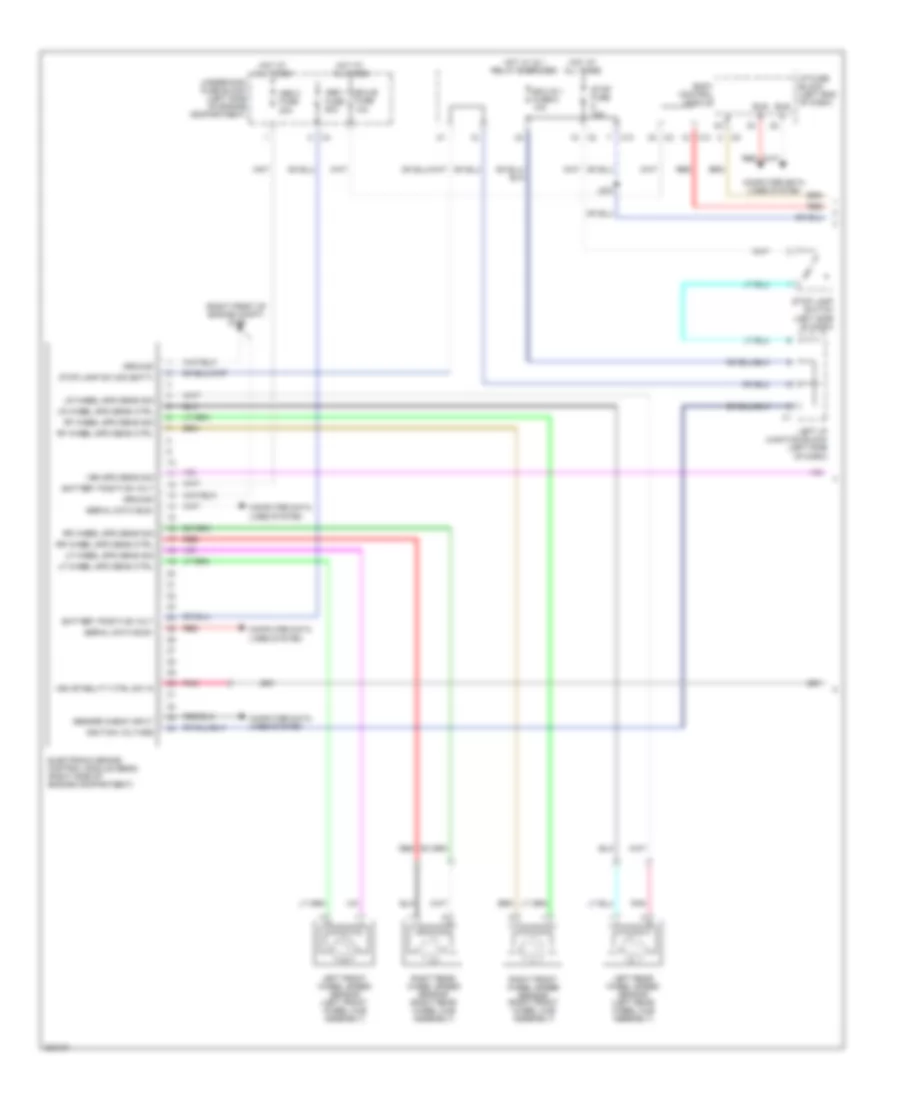
Anti-lock Brakes Wiring Diagram (1 of 2) for Pontiac Vibe 2010
List of elements for Anti-lock Brakes Wiring Diagram (1 of 2) for Pontiac Vibe 2010:
- (right front of engine compt) g106
- Abs 1 fuse 50a
- Abs 3 fuse 30a
- Battery positive volt
- Body control module
- Bus +
- Bus -
- Computer data lines system
- Ecu-b fuse 10a
- Ecu-ig 1 fuse 6 10a
- Electronic brake control module (ebcm) (right side of engine compartment)
- Ground
- Hot at all times
- Hot w/ ig 1 relay energized
- I/p fuse block (left end of dash)
- Ignition voltage
- J203
- Left front wheel speed sensor (left front wheel hub assembly)
- Left i/p junction block (left side of dash)
- Left rear wheel speed sensor (left rear wheel hub assembly)
- Lf wheel spd sens ctrl
- Lf wheel spd sens sig
- Lr wheel spd sens ctrl
- Lr wheel spd sens sig
- Pnk
- Red
- Rf wheel spd sens ctrl
- Rf wheel spd sens sig
- Right front wheel speed sensor (right front wheel hub assembly)
- Right rear wheel speed sensor (right rear wheel hub assembly)
- Rr wheel spd sens ctrl
- Rr wheel spd sens sig
- Sensor check input
- Serial data bus+
- Serial data bus-
- Stop fuse 10a
- Stop lamp sw sig (batt)
- Stop lamp switch (left side of dash)
- Underhood fuse block (left side of engine compartment)
- Veh spd sens sig
- Veh stability ctrl sw in
- X13
Anti-lock Brakes Wiring Diagram (2 of 2) for Pontiac Vibe 2010
List of elements for Anti-lock Brakes Wiring Diagram (2 of 2) for Pontiac Vibe 2010:
- (left front of engine compt) g102
- Abs ind
- Batt positive volt
- Brake fluid level switch (in brake fluid reservoir)
- Brake ind
- Computer data lines system
- Daytime running lights (drl) module (left side of dash)
- G201 (behind instrument cluster)
- Ground
- Hi spd gmlan
- I/p junction block (right side of dash)
- Ignition volt
- Instrument panel cluster (ipc)
- Interior lights system
- J104
- J220 (instrument panel harness)
- Logic
- Parking brake switch (under center console)
- Red
- Ser data bus+
- Ser data bus-
- Steering angle sensor (top of steering column)
- Vehicle stability control module (left side of dash)
- Vsc off ind
- Yaw rate & lateral accelerometer sensor (under driver's seat)
ANTI-THEFT
Anti-theft Wiring Diagram (1 of 2) for Pontiac Vibe 2010
List of elements for Anti-theft Wiring Diagram (1 of 2) for Pontiac Vibe 2010:
- (left end of dash) i/p fuse block
- Actuator sig
- Ajar sw rr door
- Auxiliary vehicle communication interface module
- Batt(+) volt
- Body control module (bcm)
- Dome fuse 10a
- Door fuse 11 25 a
- Driver door jamb switch (left "b" pillar)
- Driver door lock actuator (rear of left front door)
- Driver door lock switch
- Driver door lock window switch
- Drv dr key sw unlk sig
- Drv dr lk position sw in
- Enable sig
- G200 (left kick panel)
- G203 (right kick panel)
- G205 (right "c" pillar)
- Ground
- Hot at all times
- J500
- J600
- Jamb sw lr door
- Key cylinder switch
- Left rear door jamb switch (left "c" pillar)
- Lock detection switch
- Lock sw sig
- Passenger door ajar sw
- Passenger door jamb switch (right "b" pillar)
- Passenger door key sw
- Passenger door lock actuator (rear of right front door)
- Passenger door lock switch
- Pnk
- Position sw in pass dr lk
- Red
- Remote control door lock receiver (rcdlr) (right "c" pillar)
- Rf dr lk
- Right rear door jamb switch (right "c" pillar)
- Serial data
- Un lock sw sig
- Underhood fuse block (left side of engine compt)
- Unlk ctrl drv dr lk mtr
- W/ power windows
- W/o power windows
- X13
Anti-theft Wiring Diagram (2 of 2) for Pontiac Vibe 2010
List of elements for Anti-theft Wiring Diagram (2 of 2) for Pontiac Vibe 2010:
- (floor harness) j303
- (floor harness) j306
- B +
- Batt positive vol
- Body control module (bcm)
- Computer data lines system
- Data communication (+)
- Data communication (-)
- Data communication (-) data communication (+)
- Ecu-b fuse 10 a
- Ecu-ig fuse 6 10 a
- G200 (left kick panel)
- G201 (behind instrument cluster)
- G206 (right "c" pillar)
- G301 (left "c" pillar)
- G302 (left "c" pillar)
- Glass brk asw sens sig
- Ground
- Hot at all times
- Hot w/ ig 1 relay energized
- I/p fuse block (left end of dash)
- I/p fuse block (left end of dash) x7
- I/p junction block (right side of dash)
- Ignition key alarm switch (at ignition switch)
- Ignition volt
- Ignition voltage
- J203
- J233 (instrument panel harness)
- J235 (instrument panel harness)
- J312
- Key switch signal
- Left rear door lock actuator
- Left rear door lock actuator (rear of left rear door)
- Liftgate latch assembly (bottom center of liftgate)
- Microphone sig (+)
- Microphone sig (-)
- Motor unlock ctrl driver door lock
- Red
- Right rear door lock actuator (rear of right rear door)
- Rr dr lk position sw in
- Security ind lp sply volt
- Security indicator lamp
- Shock sens sig
- Theft deterrent module (tdm) (right side of dash)
- Theft deterrent shock sensor (right side of dash)
- Theft deterrent shock sensor microphone (left end of dash)
- Underhood fuse block (left side of engine compt)
- X13
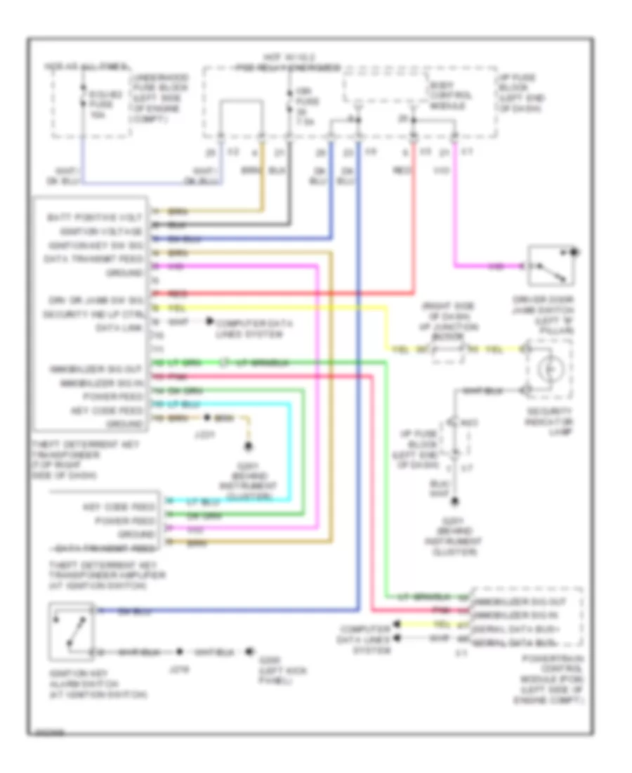
Pass-Key Wiring Diagram for Pontiac Vibe 2010
List of elements for Pass-Key Wiring Diagram for Pontiac Vibe 2010:
- (behind instrument cluster)
- (right side of dash) i/p junction block
- Batt positive volt
- Body control module
- Computer data lines system
- Data link
- Data transmit feed
- Driver door jamb switch (left "b" pillar)
- Drv dr jamb sw sig
- Ecu-b2 fuse 10a
- G200 (left kick panel)
- G201
- Ground
- Hot at all times
- Hot w/ ig 2 pcb relay energized
- I/p fuse block (left end of dash)
- Ign fuse 7.5a
- Ignition key alarm switch (at ignition switch)
- Ignition key sw sig
- Ignition voltage
- Immobilizer sig in
- Immobilizer sig out
- J219
- J231
- Key code feed
- Pnk
- Power feed
- Powertrain control module (pcm) (left side of engine compt)
- Red
- Security ind lp ctrl
- Security indicator lamp
- Serial data bus+
- Serial data bus-
- Theft deterrent key transponder (top right side of dash)
- Theft deterrent key transponder amplifier (at ignition switch)
- Underhood fuse block (left side of engine compt)
- X13
BODY CONTROL MODULES
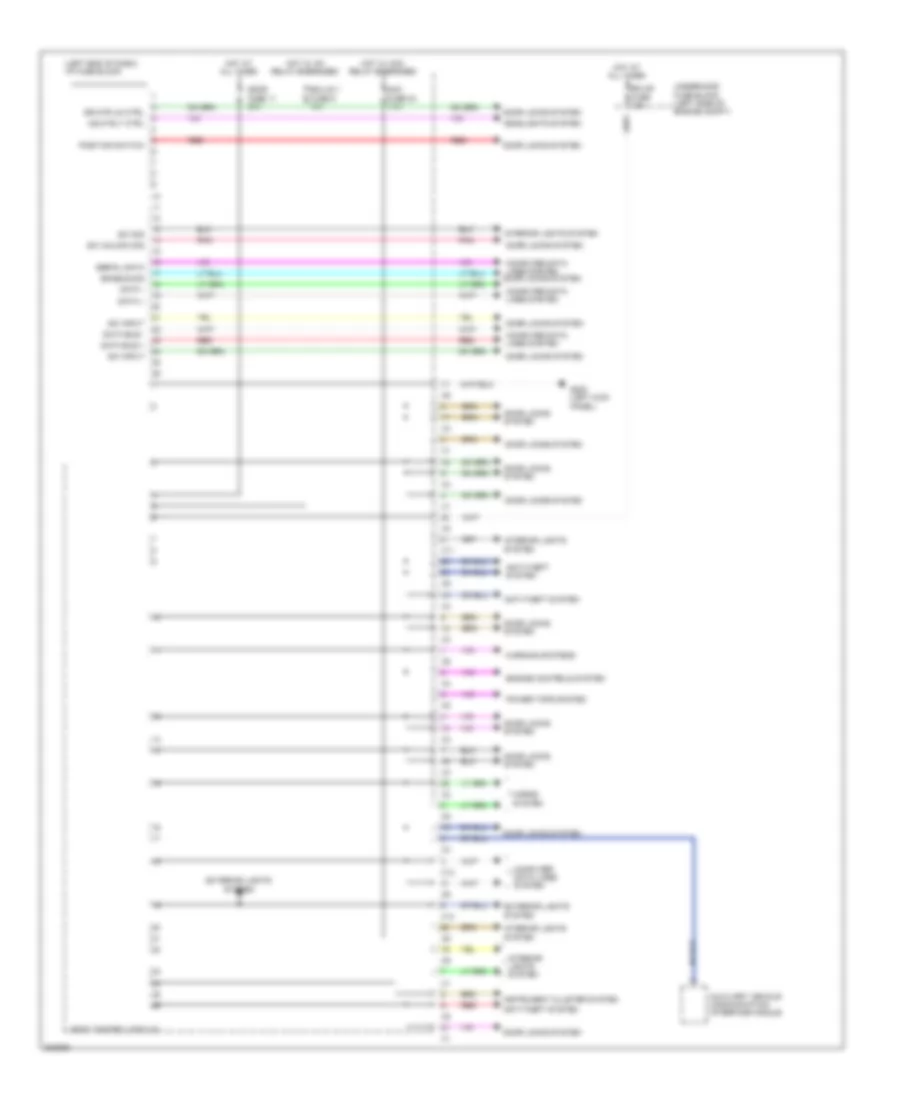
Body Control Modules Wiring Diagram for Pontiac Vibe 2010
List of elements for Body Control Modules Wiring Diagram for Pontiac Vibe 2010:
- (left end of dash) i/p fuse block
- Acc fuse 24 7.5a
- Anti-theft system
- Auxiliary vehicle communication interface module
- Body control module
- Computer data lines system
- Computer data lines system door locks system
- Data +
- Data -
- Data bus +
- Data bus -
- Door fuse 11 25a
- Door locks system
- Dr mtr un ctrl
- Ecu-b fuse 10a
- Ecu-ig 1 fuse 6 10a
- Enable sig
- Engine controls system
- Exterior lights system
- G200 (left kick panel)
- Hdlp rly ctrl
- Headlights system
- Horns system
- Hot at all times
- Hot w/ acc relay energized
- Hot w/ ig1 relay energized
- Instrument cluster system
- Interior lights system
- Pnk
- Position switch
- Power tops system
- Red
- Serial data
- Sw input
- Sw sig
- Sw unlock sig
- Underhood fuse block (left side of engine compt)
- Warning systems
- X11
- X13
COMPUTER DATA LINES
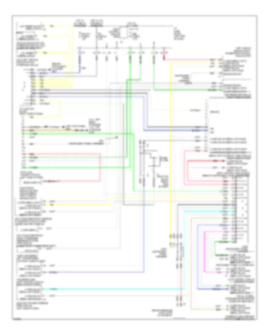
Computer Data Lines Wiring Diagram for Pontiac Vibe 2010
List of elements for Computer Data Lines Wiring Diagram for Pontiac Vibe 2010:
- (2.4l: left rear of engine (1.8l: top of engine) g105
- (behind instrument cluster) g201
- (instrument panel harness) j238
- (left kick panel) g200
- (left side of engine compt) powertrain control module (pcm)
- Auxiliary vehicle communication interface module
- Body control module (bcm)
- Body control module (bcm) (rear of instrument panel fuse block)
- Brake pressure modulator valve (bpmv)
- Data link
- Data link connector (dlc) (left side of dash)
- Ecu-ig 1 fuse 6 10a
- Electric power steering (eps) module (left side of dash)
- Electronic brake control module (ebcm) (right side of engine compt)
- Engine spd sig
- Ground
- Hi spd gmlan
- Hi spd gmlan serial data bus+
- Hi spd gmlan serial data bus-
- Hot at all times
- Hot w/ ig 1 relay energized
- Hot w/ ig 2 pcb relay energized
- Hvac control module (center of dash)
- I/p fuse block (left end of dash)
- I/p junction block (right side of dash)
- Ign
- Ign fuse 30 7.5a
- Inflatable restraint front passenger presence system (pps) module (under front passenger's seat)
- Inflatable restraint sensing & diagnostic module (sdm) (under center console)
- Instrument panel cluster (ipc)
- J203
- J204 (instrument panel harness)
- J219
- J236
- Junction block (right side of dash)
- Jx200 (instrument panel harness)
- Jx201 (instrument panel harness)
- Lo spd serial
- Lo spd serial data
- Lo spd serial data hi spd gmlan serial data bus+ hi spd gmlan serial data bus-
- Low speed gmlan serial data x2
- Low speed serial data
- Noise filter
- Obd fuse 8 7.5a
- Pnk
- Radio
- Red
- Sens check in
- Serial data bus+ hi spd gmlan serial data bus-
- Serial data bus- hi spd gmlan serial data bus+
- Serial data gateway (sdg) module (right side of dash)
- Steering angle sensor (top of steering column)
- Theft deterrent key transponder (top right side of dash)
- Tire pressure module (right side of dash)
- Transfer case shift control module (right side of dash)
- Vehicle communication interface module (vcim) (under driver's seat)
- X13
- Yaw & lateral accelerometer sensor (under driver's seat)
COOLING FAN
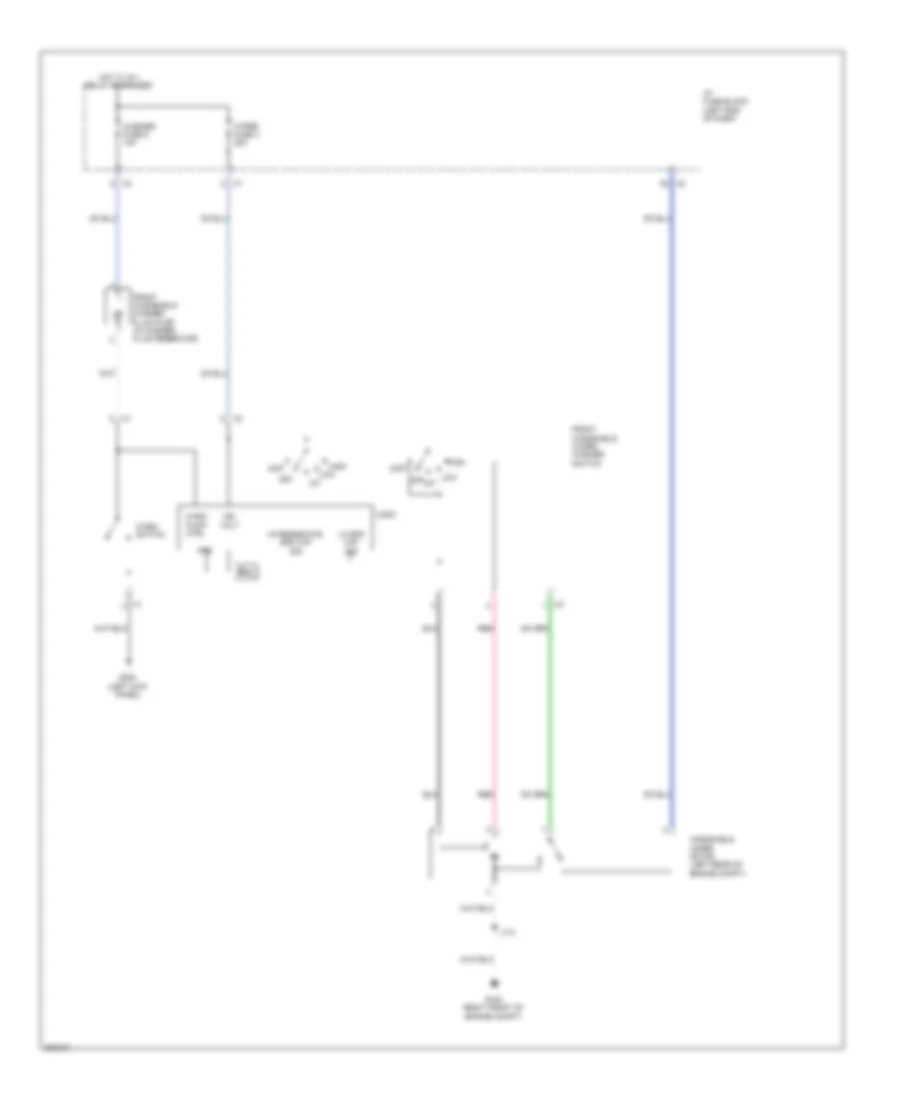
1.8L VIN 8
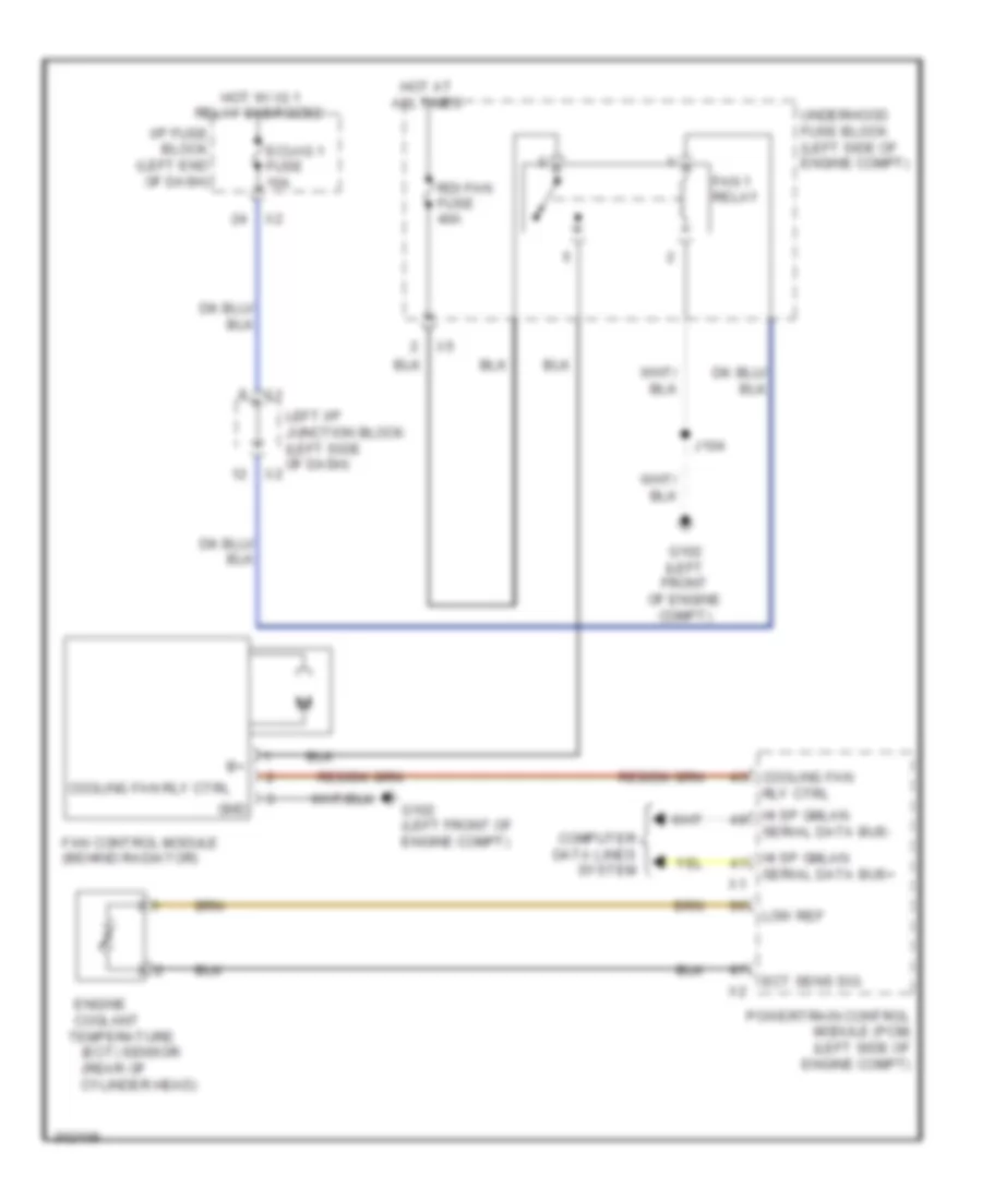
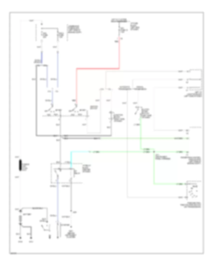
1.8L VIN 8, Cooling Fan Wiring Diagram for Pontiac Vibe 2010
List of elements for 1.8L VIN 8, Cooling Fan Wiring Diagram for Pontiac Vibe 2010:
- (rear of
- Computer data lines system
- Coolant
- Cooling fan
- Cooling fan rly ctrl
- Cylinder head)
- Ect sens sig
- Ecu-ig 1 fuse 10a
- Engine
- Fan 1 relay
- Fan control module (behind radiator)
- G102 (left front of engine compt)
- Gnd
- Hi sp gmlan
- Hot at all times
- Hot w/ ig 1 relay energized
- I/p fuse block (left end of dash)
- J104
- Left i/p junction block (left side of dash)
- Low ref
- Powertrain control module (pcm) (left side of engine compt)
- Rdi fan fuse 40a
- Rly ctrl
- Serial data bus+
- Serial data bus-
- Temperature (ect) sensor
- Underhood fuse block (left side of engine compt)
2.4L VIN 0
2.4L VIN 0, Cooling Fan Wiring Diagram for Pontiac Vibe 2010
List of elements for 2.4L VIN 0, Cooling Fan Wiring Diagram for Pontiac Vibe 2010:
- (engine room main harness) j109
- (rear of
- Cds fan fuse 30a
- Computer data lines system
- Coolant
- Cylinder head)
- Ect sens sig
- Ecu-ig 1 fuse 10a
- Engine
- Fan 1 relay
- Fan 2 relay
- Fan 3 relay
- Fan rly ctrl
- G102 (left front of engine compt)
- Hi sp gmlan
- Hot at all times
- Hot w/ ig 1 relay energized
- I/p fuse block (left end of dash)
- J104
- Left engine cooling fan (behind radiator)
- Left i/p junction block (left side of dash)
- Lo sp cooling fan rly ctrl hi sp cooling
- Low ref
- Powertrain control module (pcm) (left side of engine compt)
- Rdi fan fuse 40a
- Red
- Right engine cooling fan (behind radiator)
- Serial data bus+
- Serial data bus-
- Temperature (ect) sensor
- Underhood fuse block (left side of engine compt)
CRUISE CONTROL
Cruise Control Wiring Diagram for Pontiac Vibe 2010
List of elements for Cruise Control Wiring Diagram for Pontiac Vibe 2010:
- (or red)
- 5 volt reference
- Accelerator pedal position (app) sensor (left side of dash)
- App sensor 1 signal
- App sensor 2 signal
- Automatic transmission output shaft speed (oss) sensor (on transmission)
- Cancel
- Computer data lines system
- Cruise control switch
- Cruise ctrl sw sig
- Cruise ind
- Cruise on/off
- Drain wire
- Electronic brake control module (ebcm) (right side of engine compt)
- G105 (1.8l: top of engine) (2.4l: left rear of engine)
- High signal
- Hot at all times
- Hot w/ ig2 pcb relay energized
- I/p fuse block (left end of dash)
- Ign fuse 30 7.5a
- Ign voltage
- Inflatable restraint steering wheel module coil (under steering wheel)
- Instrument panel cluster (ipc)
- J236
- Left i/p junction block (left side of dash)
- Logic
- Low reference
- Low signal
- Low spd serial data
- Meter fuse 31 7.5a
- Mil ctrl
- Pnk
- Powertrain control module (pcm) (left side of engine compt)
- Red
- Resume/ accel
- Serial data bus (+)
- Serial data bus (-)
- Set/ coast
- Stop fuse 9 10a
- Stop lamp sw sig
- Stop lamp switch (left side of dash)
- Tac mtr ctrl 1
- Tac mtr ctrl 2
- Throttle body
- Tp sensor 1 sig
- Tp sensor 2 sig
- W/ vsc
- W/o vsc
- X12
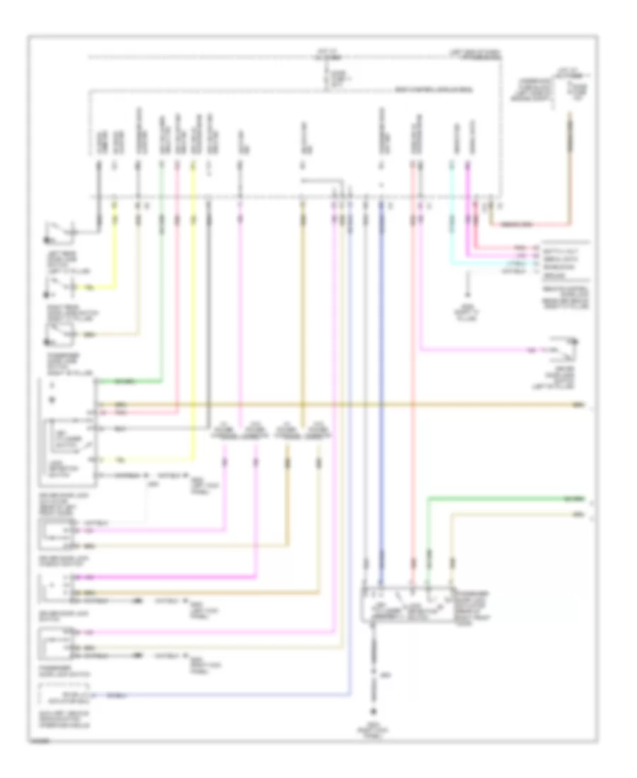
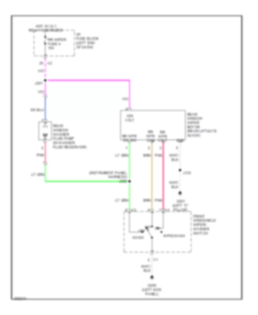
DEFOGGERS
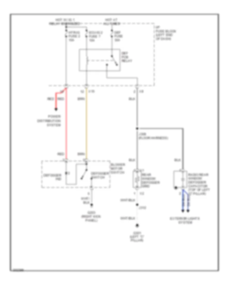
Defoggers Wiring Diagram for Pontiac Vibe 2010
List of elements for Defoggers Wiring Diagram for Pontiac Vibe 2010:
- Blower motor switch
- Def fuse 30a
- Def pcb relay
- Defogger ind
- Defogger switch
- Distribution
- Ecu-ig 2 fuse 7 10a
- Exterior lights system
- G203 (right kick panel)
- G301 (left "c" pillar)
- Hot at all times
- Hot w/ ig 1 relay energized
- Htr-ig fuse 2 10a
- I/p fuse block (left end of dash)
- J308 (floor harness)
- J312
- Power
- Rear window defogger grid
- Red
- System
- X15
ELECTRONIC POWER STEERING
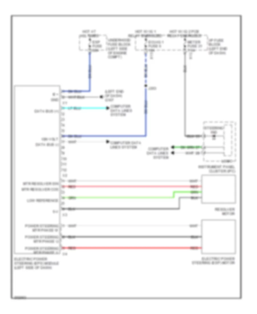
Electronic Power Steering Wiring Diagram for Pontiac Vibe 2010
List of elements for Electronic Power Steering Wiring Diagram for Pontiac Vibe 2010:
- (left end of dash) g107
- 5-v
- B +
- Computer data lines system
- Data bus (+)
- Data bus (-)
- Ecu-ig 1 fuse 6 10a x13
- Electric power steering (eps) module (left side of dash)
- Electric power steering (esp) motor
- Esp fuse 60a
- Gnd
- Hot at all times
- Hot w/ ig 1 relay energized
- Hot w/ ig 2 pcb relay energized
- I/p fuse block (left end of dash)
- Ign volt
- Instrument panel cluster (ipc)
- J203
- Logic
- Low reference
- Meter fuse 31 7.5a x12
- Mtr resolver cos
- Mtr resolver sin
- Power steering mtr phase u
- Power steering mtr phase v x4
- Power steering mtr phase w
- Red
- Resolver motor
- Steering ind
- Underhood fuse block (left side of engine compt)
ENGINE PERFORMANCE
1.8L VIN 8
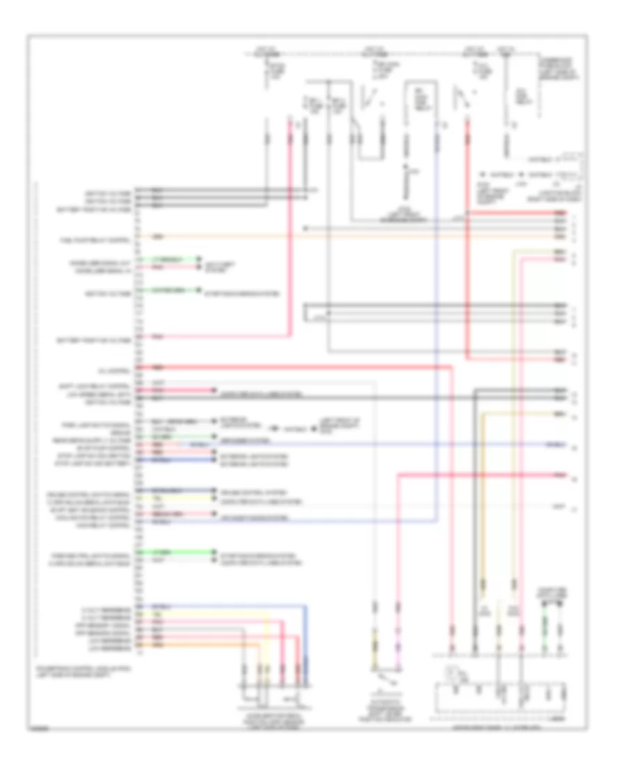
1.8L VIN 8, Engine Performance Wiring Diagram (1 of 5) for Pontiac Vibe 2010
List of elements for 1.8L VIN 8, Engine Performance Wiring Diagram (1 of 5) for Pontiac Vibe 2010:
- (left front of engine compt) g102
- 5 volt reference
- Accelerator pedal position (app) sensor (left side of dash)
- Air conditioning system
- Anti-theft system
- App sensor 1 signal
- App sensor 2 signal
- Automatic transmission shift lever position indicator
- Battery positive voltage
- Bus +
- Bus -
- Computer data lines system
- Cooling fan relay control
- Cruise control switch signal
- Cruise control system
- Defogger system
- Efi 1 fuse 10a
- Efi 2 fuse 10a
- Efi main fuse 20a
- Efi main pcb relay
- Etcs fuse 10a
- Evap pump control
- Evap vent solenoid control
- Exterior lights system
- Fuel lvl sig
- Fuel pump relay control
- G102 (left front of engine compt)
- Ground
- Hi spd gmlan serial data bus+
- Hi spd gmlan serial data bus-
- Hot at all times
- Hot in acc
- I/p junction block (right side of dash)
- Ig 2 fuse 15a
- Ig 2 pcb relay
- Ign
- Ignition voltage
- Immobilizer signal in
- Immobilizer signal out
- Instrument panel cluster (ipc)
- J101
- J104
- J114
- J117
- Logic
- Low reference
- Low speed serial data
- Main relay control
- Mil control
- Mil ind
- Park lamp switch signal
- Park/neutral switch signal
- Pnk
- Powertrain control module (pcm) (left side of engine compt)
- Red
- Shift lock relay control
- Sig (+) fuel lvl
- Starting/charging system
- Stop lamp sw sig (battery)
- Stop lamp sw sig (ignition)
- Underhood fuse block (left side of engine compt)
- W/ awd
- W/o awd
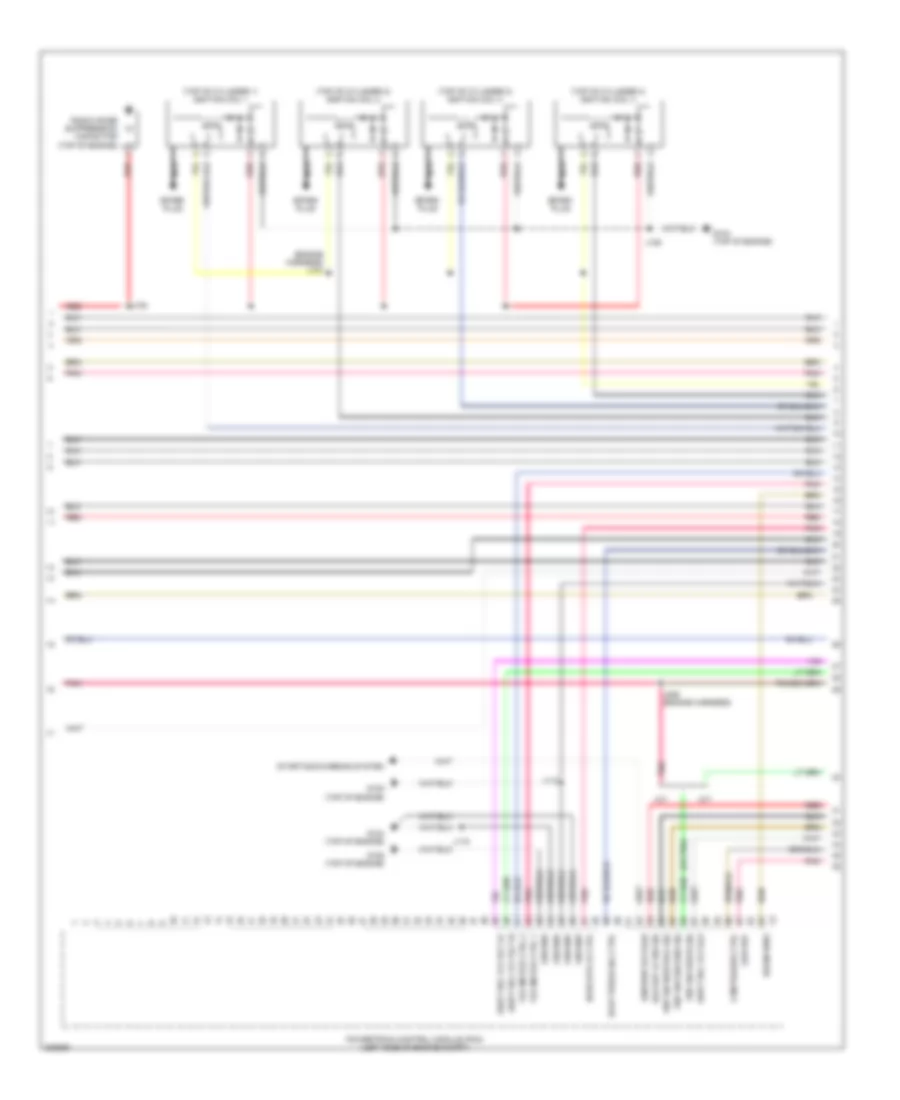
1.8L VIN 8, Engine Performance Wiring Diagram (2 of 5) for Pontiac Vibe 2010
List of elements for 1.8L VIN 8, Engine Performance Wiring Diagram (2 of 5) for Pontiac Vibe 2010:
- (engine harness) j107
- (or pnk)
- (top of cylinder 1) ignition coil 1
- (top of cylinder 2) ignition coil 2
- (top of cylinder 3) ignition coil 3
- (top of cylinder 4) ignition coil 4
- A/t
- Backup lp sw sig
- Cam phaser ctrl
- Drain wire
- Evap purge sol ctrl
- G104 (top of engine)
- G105 (top of engine)
- Ground
- Ho2s htr lo ctrl
- Ignition voltage
- J106
- J108
- J113
- J115
- J226 (engine harness)
- Low ref
- M/t
- Nca
- Pnk
- Pnp sw drive sig
- Pnp sw neutral sig
- Pnp sw second sig
- Powertrain control module (pcm) (left side of engine compt)
- Radio noise suppression capacitor (top of engine)
- Red
- Shift sol vlv slt hi
- Shift sol vlv slt lo
- Shift sol vlv slu
- Spark plug
- Starting/charging system
- Tac motor ctrl 1
- Tac motor ctrl 2
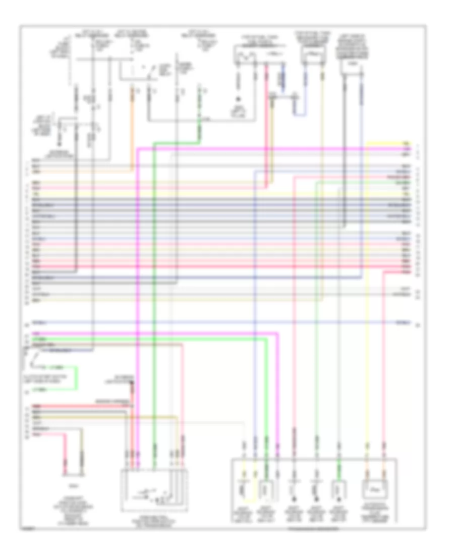
1.8L VIN 8, Engine Performance Wiring Diagram (3 of 5) for Pontiac Vibe 2010
List of elements for 1.8L VIN 8, Engine Performance Wiring Diagram (3 of 5) for Pontiac Vibe 2010:
- (engine harness) j111
- (left side of engine compt) evaporative emissions (evap) canister purge solenoid valve
- (top of fuel tank) fuel pump & sender assembly
- (top of fuel tank) secondary fuel pump & sender assembly
- Automatic transmission fluid temperature (tft) sensor
- C/opn pcb relay
- Camshaft position (cmp) actuator solenoid valve bank 2 exhaust (front of cylinder head)
- Clutch start switch (left side of dash)
- Ecu-ig 2 fuse 7 10a
- Ecu-ign 1 fuse 6 10a
- Exterior lights system
- G302 (left "c" pillar)
- Hot w/ ig 1 relay energized
- Hot w/ ig2 pcb relay energized
- I/p fuse block (left end of dash)
- Ign fuse 30 7.5a
- J116
- Left i/p junction block (left side of dash)
- Meter fuse 31 7.5a
- Park/neutral position (pnp) switch (on transmission)
- Pnk
- Red
- Shift solenoid valve (ssv) s1
- Shift solenoid valve (ssv) s2
- Shift solenoid valve (ssv) slt
- Shift solenoid valve (ssv) slu
- Shift solenoid valve (ssv) st
- Transmission connector
- W/ awd
- W/o awd
- X12
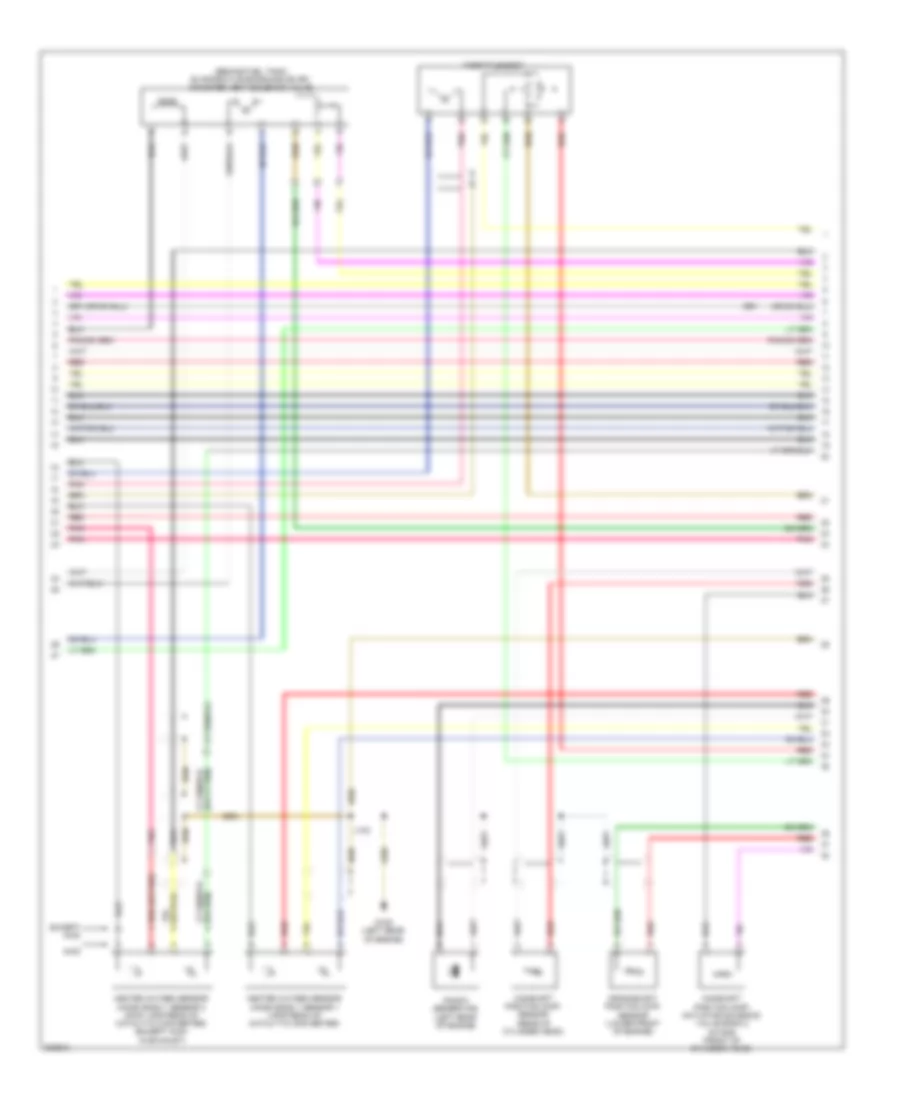
1.8L VIN 8, Engine Performance Wiring Diagram (4 of 5) for Pontiac Vibe 2010
List of elements for 1.8L VIN 8, Engine Performance Wiring Diagram (4 of 5) for Pontiac Vibe 2010:
- (behind fuel tank) evaporative emissions (evap) canister vent solenoid valve
- (in air cleaner assembly) mass air flow sensor (maf)
- (rear of cylinder head) engine coolant temperature (ect) sensor
- Crankshaft position (ckp) sensor (lower front of engine)
- G105 (top of engine)
- Heated oxygen sensor (ho2s) bank 1 sensor 1 (right rear of engine)
- Heated oxygen sensor (ho2s) bank 1 sensor 2 (upstream of catalytic converter)
- J103
- Knock sensor (ks) (left side of engine)
- Pnk
- Red
- Throttle body
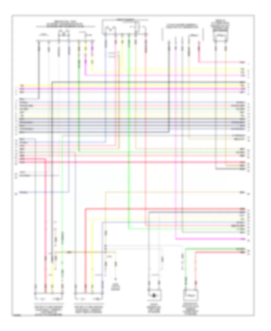
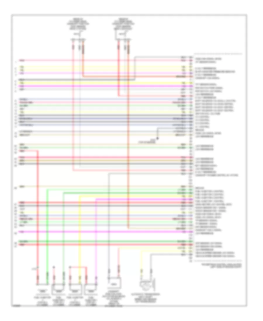
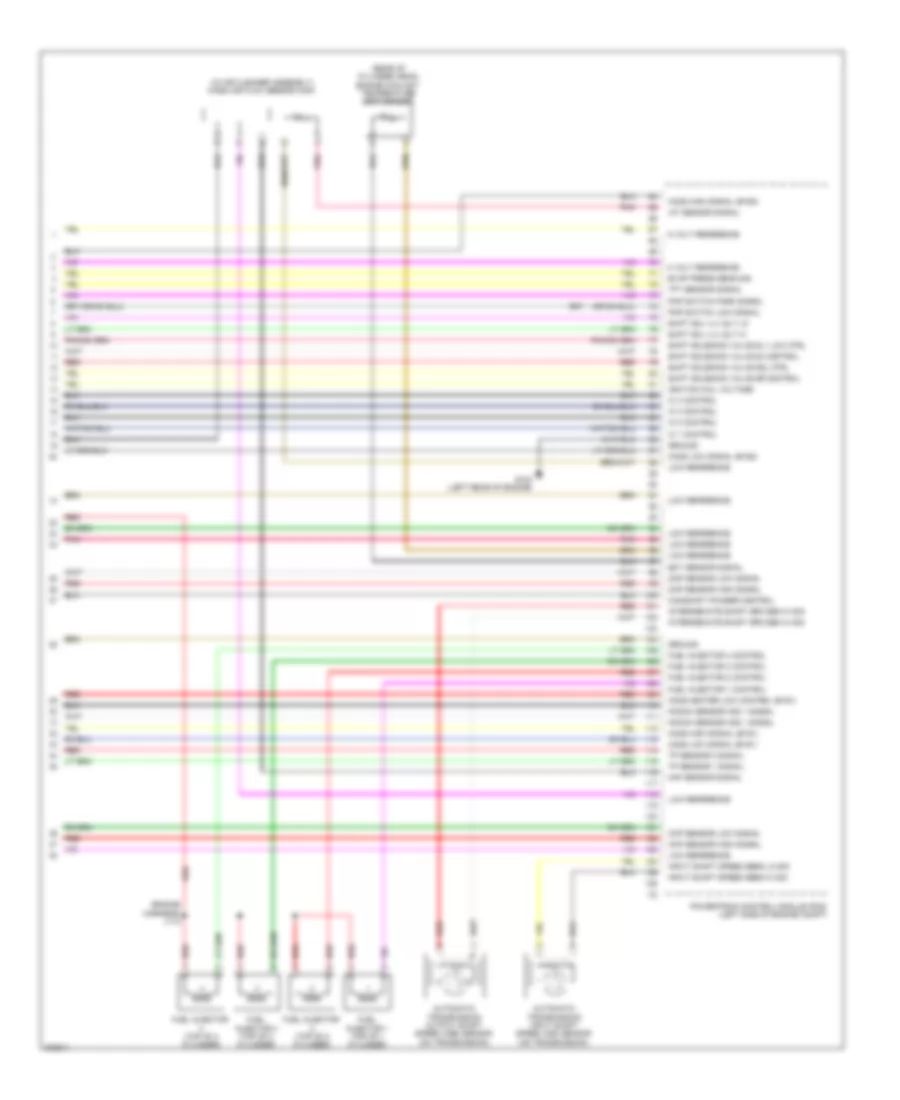
1.8L VIN 8, Engine Performance Wiring Diagram (5 of 5) for Pontiac Vibe 2010
List of elements for 1.8L VIN 8, Engine Performance Wiring Diagram (5 of 5) for Pontiac Vibe 2010:
- (rear of cylinder head) camshaft position (cmp) sensor bank 2 exhaust
- (rear of cylinder head) camshaft position (cmp) sensor bank 2 intake
- 5 volt reference
- Automatic transmission input shaft speed (iss) sensor (on transmission)
- Camshaft cam signal
- Camshaft cam x signal
- Camshaft phaser control b1 intake
- Camshaft position (cmp) actuator solenoid valve bank 2 intake (front of cylinder head)
- Ckp sensor high signal
- Ckp sensor low signal
- Ect sensor signal
- Evap canister pressure sens sig
- Fuel injector (top of 2 cylinder)
- Fuel injector (top of 4 cylinder)
- Fuel injector 1 (top of 1 cylinder)
- Fuel injector 1 control
- Fuel injector 2 control
- Fuel injector 3 (top of 3 cylinder)
- Fuel injector 3 control
- Fuel injector 4 control
- G104 (top of engine)
- Ground
- Ho2s heater low control (b1s1
- Ho2s high signal (b1s1)
- Ho2s high signal (b1s2)
- Ho2s low signal (b1s1)
- Ho2s low signal (b1s2)
- Iat sensor signal
- Ic 1 control
- Ic 2 control
- Ic 3 control
- Ic 4 control
- Ignition coil voltage
- J112
- Knock sensor (ks) 1 signal
- Low reference
- Maf sensor signal
- Pnk
- Pnp switch low signal
- Pnp switch park signal
- Powertrain control module (pcm) (left side of engine compt)
- Red
- Shift solenoid valve s1 control
- Shift solenoid valve s2 control
- Shift solenoid valve slu low ctrl
- Shift solenoid valve st control
- Tft sensor signal
- Tp sensor 1 signal
- Tp sensor 2 signal
- Vehicle speed sensor high signal
- Vehicle speed sensor low signal
2.4L VIN 0
2.4L VIN 0, Engine Performance Wiring Diagram (1 of 5) for Pontiac Vibe 2010
List of elements for 2.4L VIN 0, Engine Performance Wiring Diagram (1 of 5) for Pontiac Vibe 2010:
- (left front of engine compt) g102
- 4 speed
- 5 speed
- 5 volt reference
- Accelerator pedal position (app) sensor (left side of dash)
- Air conditioning system
- Anti-theft system
- App sensor 1 signal
- App sensor 2 signal
- Automatic transmission shift lever
- Battery positive voltage
- Bus +
- Bus -
- Computer data lines system
- Cruise control switch signal
- Cruise control system
- Defogger system
- Efi 1 fuse 10a
- Efi 2 fuse 10a
- Efi main fuse 20a
- Etcs fuse 10a
- Evap pump control
- Evap vent solenoid control
- Exterior lights system
- Fuel lvl sig
- Fuel pump relay control
- G102 (left front of engine compt)
- G201 (behind instrument cluster)
- Ground
- Hi spd gmlan serial data bus+
- Hi spd gmlan serial data bus-
- High spd cooling fan rly ctrl
- Hot at all times
- Hot in acc
- I/p junction block (right side of dash)
- Ig 2 fuse 15a
- Ig 2 pcb relay
- Ign
- Ignition voltage
- Immobilizer signal in
- Immobilizer signal out
- Instrument panel cluster (ipc)
- J101
- J104
- J114
- J117
- Logic
- Low reference
- Low spd cooling fan rly ctrl
- Low speed serial data
- Main pcb relay
- Main relay control
- Mil control
- Mil ind
- Park lamp switch signal
- Park/neutral switch signal
- Pnk
- Powertrain control module (pcm) (left side of engine compt)
- Red
- Shift lever
- Shift switch tap down signal
- Shift switch tap up signal
- Sig (+) fuel lvl
- Starting/charging system
- Stop lamp sw sig (battery)
- Stop lamp sw sig (ignition)
- Underhood fuse block (left side of engine compt)
- W/ awd
- W/o awd
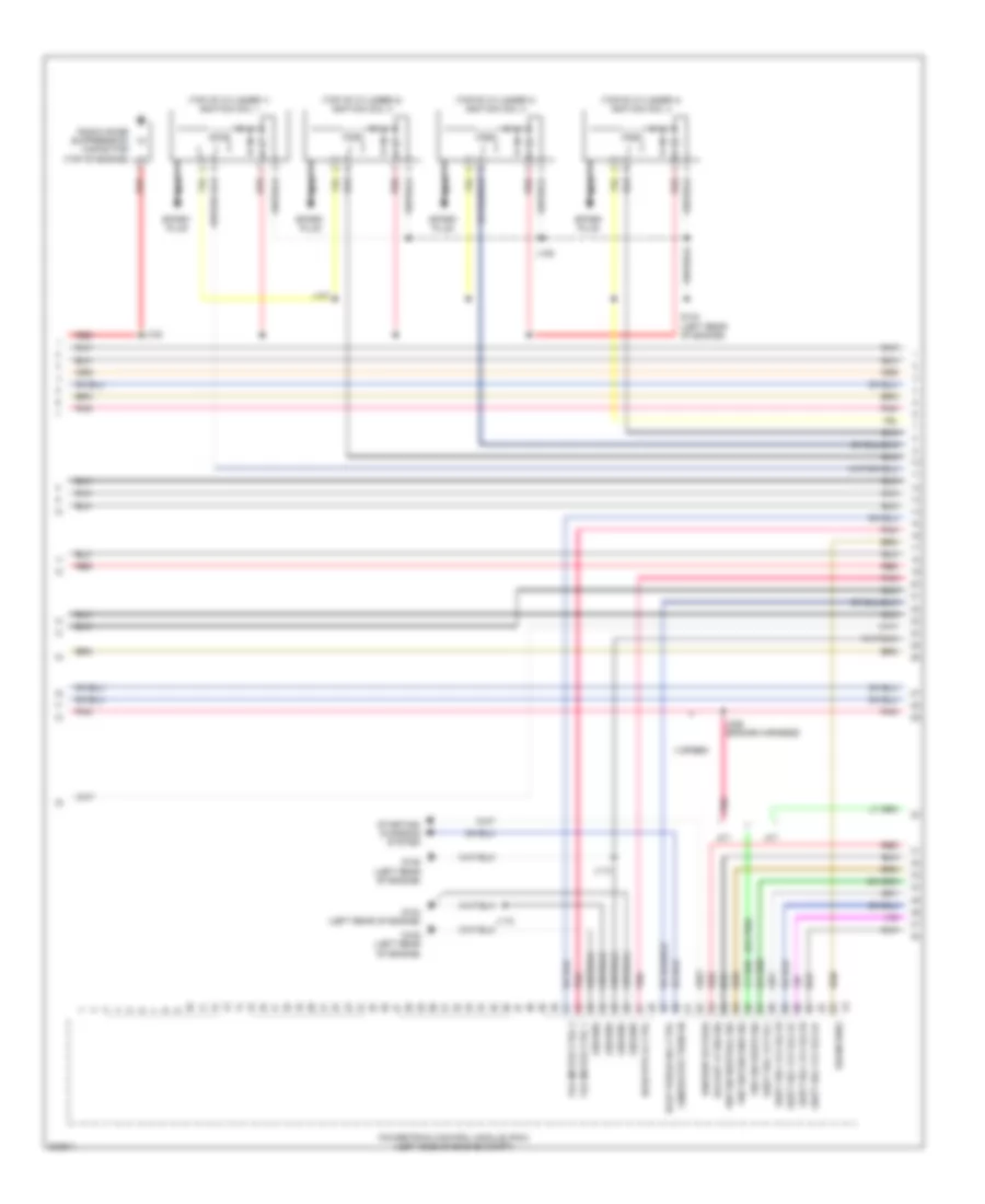
2.4L VIN 0, Engine Performance Wiring Diagram (2 of 5) for Pontiac Vibe 2010
List of elements for 2.4L VIN 0, Engine Performance Wiring Diagram (2 of 5) for Pontiac Vibe 2010:
- (or pnk)
- (top of cylinder 1) ignition coil 1
- (top of cylinder 2) ignition coil 2
- (top of cylinder 3) ignition coil 3
- (top of cylinder 4) ignition coil 4
- 4 speed
- A/t
- Backup lp sw sig
- Drain wire
- Evap purge sol ctrl
- G104 (left rear of engine)
- G105 (left rear of engine)
- Generator turn on
- Ground
- Ho2s htr lo ctrl
- Ignition voltage
- J106
- J107
- J108
- J113
- J115
- J226 (engine harness)
- M/t
- Nca
- Pnk
- Pnp sw drive sig
- Pnp sw neutral sig
- Pnp sw second sig
- Powertrain control module (pcm) (left side of engine compt)
- Radio noise suppression capacitor (top of engine)
- Red
- Shift sol vlv sl1
- Shift sol vlv sl2 hi
- Shift sol vlv sl2 lo
- Shift sol vlv sl3 hi
- Shift sol vlv sl3 lo
- Spark plug
- Starting/ charging system
- Tac motor ctrl 1
- Tac motor ctrl 2
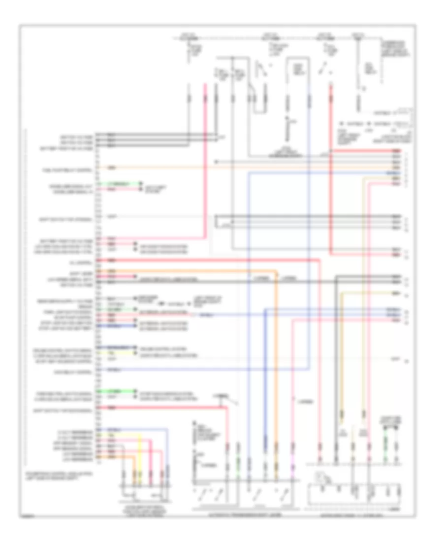
2.4L VIN 0, Engine Performance Wiring Diagram (3 of 5) for Pontiac Vibe 2010
List of elements for 2.4L VIN 0, Engine Performance Wiring Diagram (3 of 5) for Pontiac Vibe 2010:
- (engine harness) j111
- (left side of engine compt) evaporative emissions (evap) canister purge solenoid valve
- (top of fuel tank) fuel pump & sender assembly
- (top of fuel tank) secondary fuel pump & sender assembly
- 4 speed
- 5 speed
- Automatic transmission fluid temperature (tft) sensor
- C/opn pcb relay
- Clutch start switch (left side of dash)
- Ecu-ig 1 fuse 6 7.5a
- Ecu-ig 2 fuse 7 10a
- Ecu-ign 1 fuse 6 10a
- Exterior lights system
- G302 (left "c" pillar)
- Hot w/ ig 1 relay energized
- Hot w/ ig2 pcb relay energized
- I/p fuse block (left end of dash)
- Ign fuse 30 7.5a
- J116
- J203
- Left i/p junction block (left side of dash)
- Meter fuse 31 7.5a
- Park/neutral position (pnp) switch (on transmission)
- Pnk
- Red
- Shift solenoid valve (ssv) dsl
- Shift solenoid valve (ssv) s4
- Shift solenoid valve (ssv) sl1
- Shift solenoid valve (ssv) sl2
- Shift solenoid valve (ssv) sl3 (5 speed)
- Shift solenoid valve (ssv) slt
- Shift solenoid valve (ssv) sr
- Speed
- Transmission connector
- W/ awd
- W/o awd
- X12
- X13
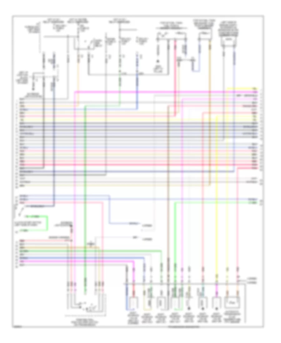
2.4L VIN 0, Engine Performance Wiring Diagram (4 of 5) for Pontiac Vibe 2010
List of elements for 2.4L VIN 0, Engine Performance Wiring Diagram (4 of 5) for Pontiac Vibe 2010:
- (behind fuel tank) evaporative emissions (evap) canister vent solenoid valve
- (or pnk)
- Awd
- Camshaft position (cmp) actuator solenoid valve bank 2 intake (front of cylinder head)
- Camshaft position (cmp) sensor (rear of cylinder head)
- Crankshaft position (ckp) sensor (lower front of engine)
- Except awd
- G105 (left rear of engine)
- Heated oxygen sensor (ho2s) bank 1 sensor 1 (upstream of catalytic converter)
- Heated oxygen sensor (ho2s) bank 1 sensor 2 (awd: upstream of catalytic converter) (except awd: in exhaust)
- J103
- Knock sensor (ks) (left rear of engine)
- Pnk
- Red
- Throttle body
2.4L VIN 0, Engine Performance Wiring Diagram (5 of 5) for Pontiac Vibe 2010
List of elements for 2.4L VIN 0, Engine Performance Wiring Diagram (5 of 5) for Pontiac Vibe 2010:
- (engine harness) j112
- (in air cleaner assembly) mass air flow sensor (maf)
- (rear of cylinder head) engine coolant temperature (ect) sensor
- 5 volt reference
- Automatic transmission input shaft speed (iss) sensor (on transmission)
- Automatic transmission output shaft speed (oss) sensor (on transmission)
- Camshaft phaser control
- Ckp sensor high signal
- Ckp sensor low signal
- Cmp sensor high signal
- Cmp sensor low signal
- Ect sensor signal
- Evap press sens sig
- Fuel injector (top of 2 cylinder)
- Fuel injector (top of 4 cylinder)
- Fuel injector 1 (top of 1 cylinder)
- Fuel injector 1 control
- Fuel injector 2 control
- Fuel injector 3 (top of 3 cylinder)
- Fuel injector 3 control
- Fuel injector 4 control
- G104 (left rear of engine)
- Ground
- Ho2s heater low control (b1s1)
- Ho2s high signal (b1s1)
- Ho2s high signal (b1s2)
- Ho2s low signal (b1s1)
- Ho2s low signal (b1s2)
- Iat sensor signal
- Ic 1 control
- Ic 2 control
- Ic 3 control
- Ic 4 control
- Ignition coil voltage
- Input shaft speed sens hi sig
- Input shaft speed sens lo sig
- Intermediate shaft spd sen hi sig
- Knock sensor (ks) 1 signal
- Low reference
- Maf sensor signal
- Pnk
- Pnp switch low signal
- Pnp switch park signal
- Powertrain control module (pcm) (left side of engine compt)
- Red
- Shift sol vlv slt hi
- Shift sol vlv slt lo
- Shift solenoid valve dsl ctrl
- Shift solenoid valve s4 control
- Shift solenoid valve sl1 low ctrl
- Shift solenoid valve sr control
- Tft sensor signal
- Tp sensor 1 signal
- Tp sensor 2 signal
EXTERIOR LIGHTS
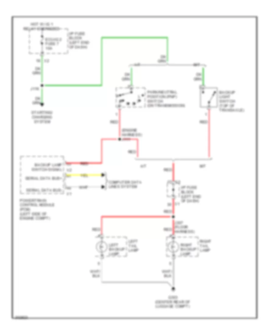
Backup Lamps Wiring Diagram for Pontiac Vibe 2010
List of elements for Backup Lamps Wiring Diagram for Pontiac Vibe 2010:
- (engine harness) j111
- A/t
- Backup lamp switch signal x2
- Backup light switch (top of transaxle)
- Computer data lines system
- Ecu-ig 2 fuse 7 10a
- G303 (center rear of luggage compt)
- Hot w/ ig 1 relay energized
- I/p fuse block (left end of dash)
- J116
- J307 (floor red harness)
- Left backup lamp
- Left tail lamp
- M/t
- Park/neutral position (pnp) switch (on transmission)
- Powertrain control module (pcm) (left side of engine compt)
- Red
- Right backup lamp
- Right tail lamp
- Serial data bus+
- Serial data bus-
- Starting/ charging system
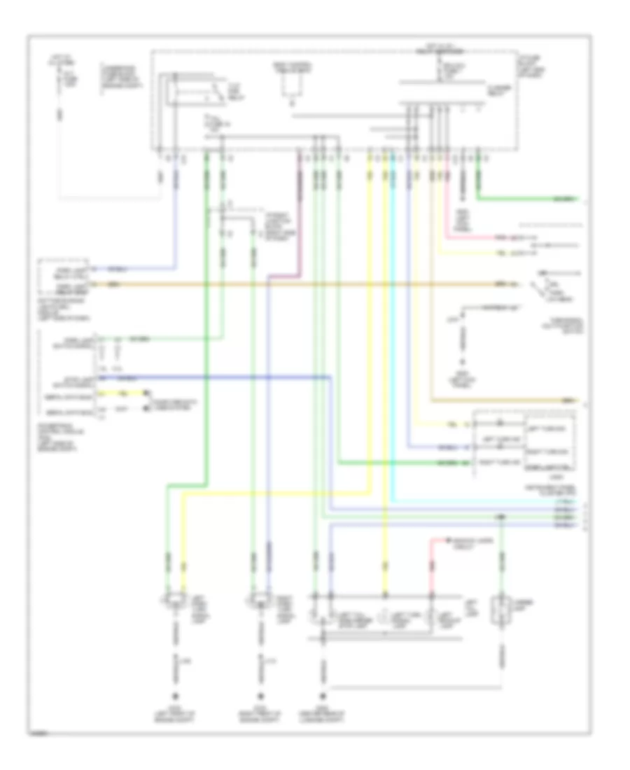
Exterior Lamps Wiring Diagram (1 of 2) for Pontiac Vibe 2010
List of elements for Exterior Lamps Wiring Diagram (1 of 2) for Pontiac Vibe 2010:
- 1.8l
- 2.4l
- Alt fuse 120a
- Backup lamps circuit
- Body control module (bcm)
- Computer data lines system
- Daytime running lights (drl) module (left side of dash)
- Drl
- Ecu-ig 2 fuse 7 10a
- Flasher relay
- G102 (left front of engine compt)
- G103 (right front of engine compt)
- G200 (left kick panel)
- G303 (center rear of luggage compt)
- Hot at all times
- Hot w/ ig 1 relay energized
- I/p fuse block (left end of dash)
- I/p right junction block (right side of dash)
- Instrument panel cluster (ipc)
- J105
- J110
- J219
- J302
- Left backup lamp
- Left park/ turn signal lamp
- Left tail lamp
- Left tail/ side marker stop lamp
- Left turn ind
- Left turn sig
- Left turn signal lamp
- License lamp
- Logic
- Low beam
- Off
- Park
- Park lamp ctrl
- Park lamp relay ctrl
- Park lamp relay gnd
- Park lamp switch signal x1
- Pnk
- Powertrain control module (pcm) (left side of engine compt)
- Red
- Right park/ turn signal lamp
- Right turn ind
- Right turn sig
- Serial data bus+
- Serial data bus-
- Stop lamp switch signal
- T-lp pcb relay
- Tail fuse 16 10a
- Turn/signal multi-function switch
- Underhood fuse block (left side of engine compt)
- X13
Exterior Lamps Wiring Diagram (2 of 2) for Pontiac Vibe 2010
List of elements for Exterior Lamps Wiring Diagram (2 of 2) for Pontiac Vibe 2010:
- (floor harness) j305
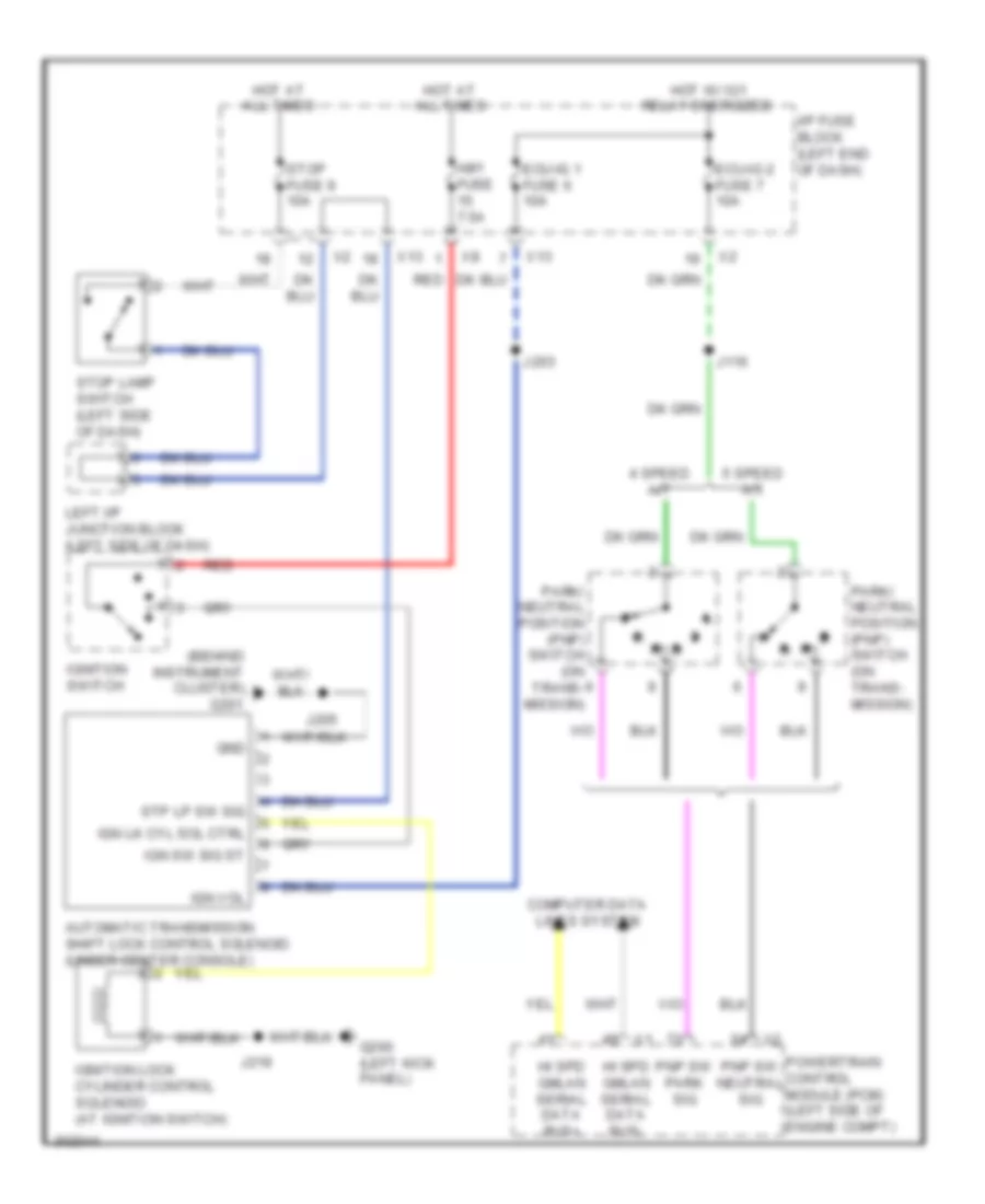
- Automatic transmission shift lock control solenoid (under center console)
- Auxiliary vehicle communication interface modules
- Backup lamps circuit
- Center high mounted stop lamp (chmsl)
- Computer data lines system
- Cruise control system
- Defogger system
- Electronic brake control module (ebcm) (right side of engine compt)
- G200 (left kick panel)
- G301 (left "c" pillar)
- G303 (center rear of luggage compt)
- Hazard switch signal
- Hazard warning switch
- Hot at all times
- I/p fuse block (left end of dash)
- I/p fuse block (left end of dash) x6
- I/p junction block (right side of dash)
- I/p left junction block (left side of dash)
- Interior lights system
- J312
- Low speed serial data
- Radio rear window defogger capacitor (top of left "c" pillar)
- Red
- Right backup lamp
- Right tail lamp
- Right tail/ side marker stop lamp
- Right turn signal lamp
- Serial data bus+
- Serial data bus-
- Stop fuse 9 10a
- Stop lamp switch (left side of dash)
- Stop lamp switch signal
- Turn-haz fuse 10a
- Underhood fuse block (left side of engine compt)
- W/ vsc
- W/o vsc
- X13
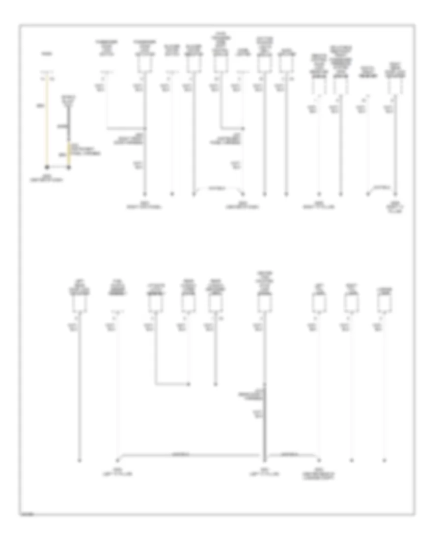
GROUND DISTRIBUTION
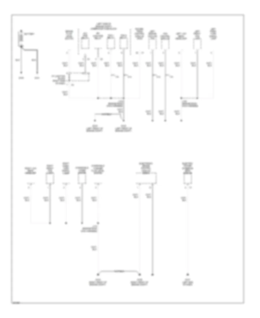
Ground Distribution Wiring Diagram (1 of 4) for Pontiac Vibe 2010
List of elements for Ground Distribution Wiring Diagram (1 of 4) for Pontiac Vibe 2010:
- (left side of engine compt) underhood fuse block
- 1.8l
- 2.4l
- Battery
- Brake fluid level switch
- Efi main pcb relay
- Electric power steering (eps) module
- Electronic brake control module (ebcm)
- Fan 1 relay
- Fan 2 relay
- Fan control module
- G100
- G101
- G102 (left front of engine compt)
- G103 (right front of engine compt)
- G106 (right front of engine compt)
- G107 (left end of dash)
- G109 (left front of engine compt)
- I/p junction block (right side of dash)
- Ig 2 pcb relay
- J104 (engine room main harness)
- J105 (engine room main harness)
- J110 (engine room main harness)
- Left engine cooling fan
- Left front fog lamp
- Left low beam headlamp
- Left park/ turn signal lamp
- Power- train control module (pcm)
- Right front fog lamp
- Right low beam headlamp
- Right park/ turn signal lamp
- Windshield washer fluid level switch
- Windshield wiper motor
Ground Distribution Wiring Diagram (2 of 4) for Pontiac Vibe 2010
List of elements for Ground Distribution Wiring Diagram (2 of 4) for Pontiac Vibe 2010:
- (left side of engine compt) underhood fuse block
- A/c compressor clutch
- Bare
- Crankshaft position (ckp) sensor shield
- Cruise control switch
- Data link connector (dlc)
- Evaporative emission (evap) canister vent solenoid valve
- G104 (1.8l: top of engine) (2.4l: left rear of engine)
- G105 (1.8l: top of engine) (2.4l: left rear of engine)
- G108 (right end of dash)
- Htr sub 1 relay
- Htr sub 3 relay
- Ignition coil 1
- Ignition coil 2
- Ignition coil 3
- Ignition coil 4
- Inflatable restraint steering wheel module coil
- J103 (engine harness)
- J106 (engine harness)
- J113 (engine harness)
- J115 (engine harness)
- J213 (instrument panel harness)
- J236 (instrument panel harness)
- Knock sensor (ks) shield
- Powertrain control module (pcm)
- Ptc heater assembly
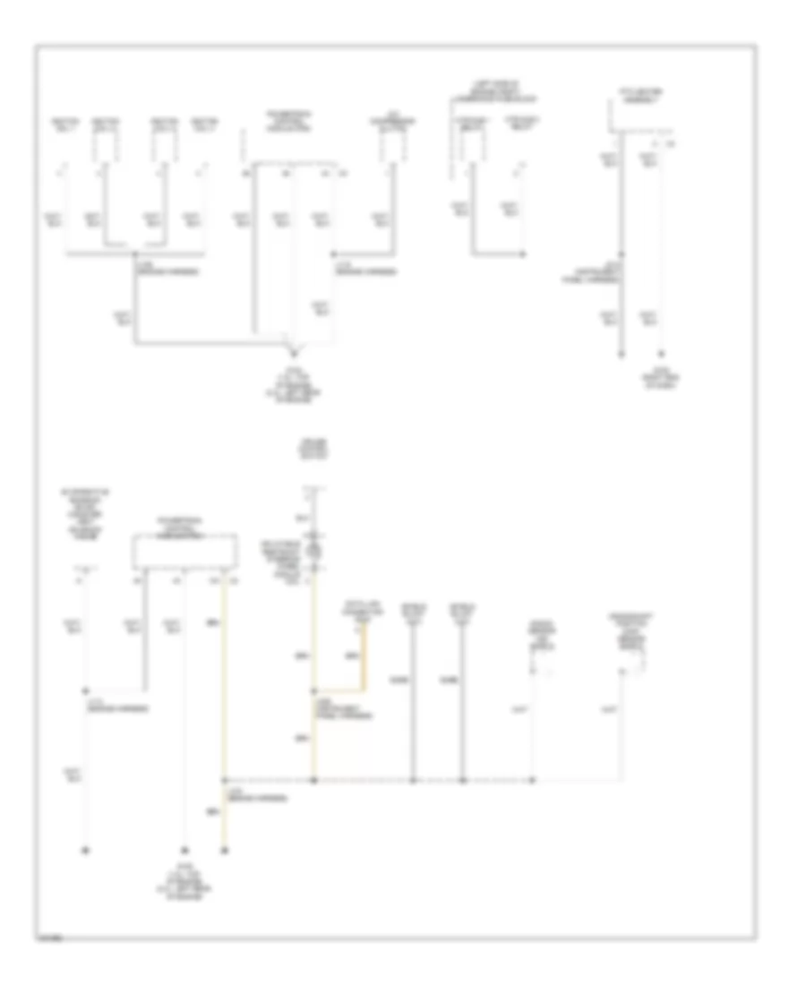
Ground Distribution Wiring Diagram (3 of 4) for Pontiac Vibe 2010
List of elements for Ground Distribution Wiring Diagram (3 of 4) for Pontiac Vibe 2010:
- (awd)
- (awd) serial data gateway (sdg) module
- (center of dash) i/p realy block
- (left side of engine compt) underhood relay block
- (right side of dash) junction block
- (w/ sliding sunroof) dome/ reading lamps
- (w/o sliding sunroof) dome/ reading lamps
- 110v ac accessory power outlet
- 2nd row courtesy/ reading lamps
- 3rd row courtesy/ reading lamps
- Acc relay
- Accessory ac/dc power control module
- Accessory power inverter module
- Automatic transmission shift lever
- Automatic transmission shift lock control solenoid
- Auxiliary vehicle communi- cation interface module
- Body control module (bcm)
- Data link connector (dlc)
- Daytime running lights (drl) module
- Driver door lock actuator
- Driver door lock switch
- Driver door/ lock window switch
- Flasher relay
- Front windshield wiper/ washer switch
- G200 (left kick panel)
- G201 (behind instrument cluster)
- Hazard warning switch
- Htr relay
- Hvac control module
- Hvac mode switch
- I/p fuse block (left end of dash)
- I/p junction block (right side of dash)
- Ig 1 relay
- Ignition key alarm switch
- Ignition lock cylinder control switch
- Inflatable restraint sensing & diagnostic module (sdm)
- Instrument panel cluster (ipc)
- J205 (instrument panel harness)
- J218 (instrument panel harness)
- J219 (instrument panel harness)
- J231 (instrument panel harness)
- J311 (roof harness)
- J500 (left front door harness)
- Noise filter
- Outside rearview mirror switch
- Pwr outlet relay
- Pwr pcb relay
- Rear window wiper/ washer switch
- Security indicator lamp
- St relay
- Steering angle sensor
- Sunroof motor
- Sunroof switch
- Theft deterrent key transponder
- Theft deterrent module (tdm)
- Theft deterrent shock sensor
- Tire pressure indicator reset switch
- Tire pressure module
- Turn signal/ multi- function switch
- Vehicle communi- cation interface module (vcim)
- Vehicle stability control module
- W/ power windows
- W/o power windows
- X11
- X12
- X13
- Yaw & lateral accelero- meter sensor
Ground Distribution Wiring Diagram (4 of 4) for Pontiac Vibe 2010
List of elements for Ground Distribution Wiring Diagram (4 of 4) for Pontiac Vibe 2010:
- (awd) transfer case shift control module
- Audio amplifier
- Bare
- Blower motor resistor
- Blower motor switch
- Center high mounted stop lamp (chmsl)
- Cigar lighter
- Daytime running lights (drl) module
- Digital radio receiver
- Fuel pump & sender assembly
- G202 (center of dash)
- G203 (right kick panel)
- G204 (center of dash)
- G205 (right "c" pillar)
- G206 (right "c" pillar)
- G301 (left "c" pillar)
- G302 (left "c" pillar)
- G303 (center rear of luggage compt)
- Inflatable restraint front passenger presence system (pps) module
- J237 (instrument panel harness)
- J312 (rear door 1 harness)
- J600 (right front door harness)
- Left rear door lock actuator
- Left tail lamp
- License lamp
- Liftgate latch assembly
- Passenger door lock actuator
- Passenger door lock switch
- Radio
- Rear window defogger grid
- Rear window wiper motor
- Remote control door lock receiver (rcdlr)
- Right rear door lock actuator
- Right tail lamp
HEADLIGHTS
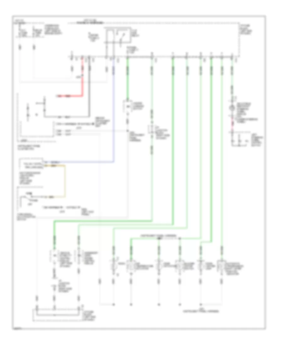
Headlights Wiring Diagram for Pontiac Vibe 2010
List of elements for Headlights Wiring Diagram for Pontiac Vibe 2010:
- (center of dash) i/p relay block
- (engine room main harness) j102
- (instrument panel harness) j225
- Air conditioning system
- Ambient light sensor (top left side of dash)
- Ambt lt sens pwr
- Ambt lt sens sig
- Batt volt
- Body control module (bcm)
- D c c
- Daytime running lights (drl) module (left side of dash)
- Dim rly ctrl
- Dimmer relay
- Drl ind
- Drl ind ctrl
- Ecu-b fuse 10a
- Ecu-ig 1 fuse 6 10a
- Exterior lights system
- Fog lamp ind
- Fog lamp switch
- Fog lp sw sig
- Fr fog fuse 14 15a
- Fr fog relay
- G102 (left front of engine compt)
- G103 (right front of engine compt)
- G200 (left kick panel)
- G201 (behind instrument cluster)
- G204 (center of dash)
- Gnd
- Ground
- H-lp lh hi fuse 10a
- H-lp lh lo fuse 10a
- H-lp main fuse 50a
- H-lp relay
- H-lp rh hi fuse 10a
- H-lp rh lo fuse 10a
- Hdlp ind ctrl
- Head
- Headlamp indicator
- Hi beam hdlps gnd
- Hi beam sig
- Hlp rly ctrl
- Hot at all times
- Hot w/ ig1 relay energized
- I/p fuse block (left end of dash)
- I/p junction block (right side of dash)
- Ign volt
- Instrument panel cluster (ipc)
- J105
- J110
- J203
- J219
- J220 (instrument panel harness)
- J230
- J231
- Left front fog lamp
- Left high beam headlamp
- Left low beam headlamp
- Lo batt ind sig
- Logic
- Off
- Park
- Park brk sw sig
- Park lamp sw sig
- Park lp rly ctrl
- Park lp rly gnd
- Park lp/hdlp sig
- Parking brake switch (under center console)
- Pnk
- Power distribution system
- Pwr
- Red
- Right front fog lamp
- Right high beam headlamp
- Right i/p junction block (right side of dash)
- Right low beam headlamp
- Sig
- Starting/ charging system
- Turn signal/multi-function switch
- Underhood fuse block (left side of engine compt)
- X12
- X13
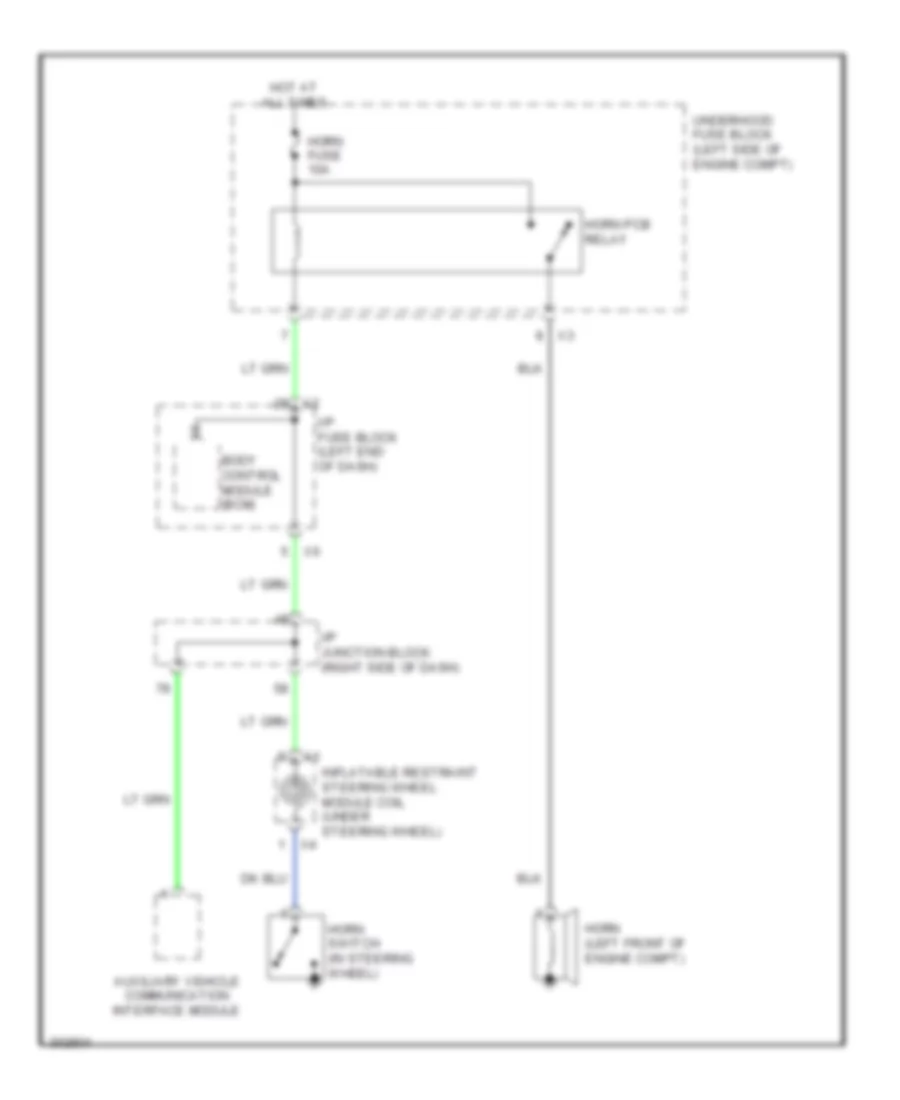
HORN
Horn Wiring Diagram for Pontiac Vibe 2010
List of elements for Horn Wiring Diagram for Pontiac Vibe 2010:
- Auxiliary vehicle communication interface module
- Body control module (bcm)
- Horn (left front of engine compt)
- Horn fuse 10a
- Horn pcb relay
- Horn switch (in steering wheel)
- Hot at all times
- I/p fuse block (left end of dash)
- I/p junction block (right side of dash)
- Inflatable restraint steering wheel module coil (under steering wheel)
- Underhood fuse block (left side of engine compt)
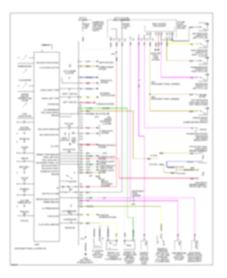
INSTRUMENT CLUSTER
Instrument Cluster Wiring Diagram for Pontiac Vibe 2010
List of elements for Instrument Cluster Wiring Diagram for Pontiac Vibe 2010:
- (instrument panel harness)
- (top of fuel tank) fuel pump & sender assembly
- Abs ind
- Air bag ind
- Ambient air temperature sensor (left front of engine compt)
- Ambient temp sens sig
- Awd ind
- Body control module (bcm)
- Brake fluid level switch (in brake fluid reservoir)
- Brake ind
- Brake indication ctrl
- Charging ind
- Computer data lines system
- Cruise ind
- Daytime running lights (drl) module (left side of dash)
- Dimmer sw output
- Display
- Door ajar ind
- Driver door jamb switch (left "b" pillar)
- Drl indicator ctrl
- Ecu-b fuse 10a
- Electronic brake control module (ebcm) (right side of engine compt)
- Engine controls system
- Engine coolant temperature gauge
- Engine oil pressure (eop) switch (1.8l: left side of engine) (2.4l: rear of cylinder head)
- Exterior lights system
- Fluid level sens sig
- Fluid level switch
- Fog lamp ind
- Fog lights indicator
- Fuel level gauge
- Fuel level sig (+)
- Fuel level signal
- Fuel pump & sender assembly (top of fuel tank)
- G102 (left front of engine compt)
- G201 (behind instrument cluster)
- Gmlan data bus +
- Gmlan data bus -
- Ground
- Headlights system
- High beam ind
- Hot at all times
- Hot w/ ig 2 pcb relay energized
- I/p fuse block (left end of dash)
- I/p junction block (right side of dash)
- Ignition voltage
- Ill
- Instrument panel cluster (ipc)
- Instrument panel low
- Interior lights system
- J104
- J219
- J220 (instrument panel harness)
- J230
- J231
- J240
- J241 (instrument panel harness)
- Left rear door jamb switch (left "c" pillar)
- Left turn ind
- Logic
- Low fuel warning ind
- Low pressure ind
- Low reference
- Low tire pressure ind
- Low washer fluid ind
- Malfunction ind
- Meter fuse 31 7.5a
- Mil ctrl
- Odo/trip
- Oil pressure sig
- Park lamp ctrl
- Parking brake switch (under center console)
- Passenger door jamb switch (right "b" pillar)
- Pnk
- Powertrain control module (pcm) (left side of engine compt)
- Prk brk sw sig
- Red
- Right rear door jamb switch (right "c" pillar)
- Right turn ind
- Seat belt ind
- Seats system
- Signal left turn
- Signal right turn
- Sir indicator control
- Speed sens sig
- Speedometer
- Starting/ charging system
- Steering ind
- Sunroof control module (forward of sun roof)
- System sig
- Tachometer
- Tire pressure module (right side of dash)
- Traction ind
- Turn on sig
- Underhood fuse block (left side of engine compt)
- Vsc off ind
- Vss
- Vss sig
- W/ awd
- W/o awd
- Warning systems
- Wiper/washer system
- X12
- X13
INTERIOR LIGHTS
Courtesy Lamps Wiring Diagram for Pontiac Vibe 2010
List of elements for Courtesy Lamps Wiring Diagram for Pontiac Vibe 2010:
- (roof harness) j309
- 2nd row courtesy/ reading lamps
- 3rd row courtesy/ reading lamps
- Ajar sw sig lr dr
- Body control module (bcm)
- Dome fuse 10a
- Dome/ reading lamps (w/ sunroof)
- Dome/ reading lamps (w/o sunroof)
- Driver door jamb switch (left "b" pillar)
- Drv dr ajar sw sig
- G301 (left "c" pillar)
- Gnd
- Hot at all times
- I/p fuse block (left end of dash)
- J310 (roof harness)
- J311 (roof harness)
- J312
- Left rear door jamb switch (left "c" pillar)
- Liftgate ajar sw sig
- Liftgate latch assembly (bottom center of liftgate)
- Pass dr ajar sw sig
- Passenger door jamb switch (right "b" pillar)
- Pnk
- Right rear door jamb switch (right "c" pillar)
- Rr dr ajar sw sig
- Underhood fuse block (left side of engine compt)
- X11
Instrument Illumination Wiring Diagram for Pontiac Vibe 2010
List of elements for Instrument Illumination Wiring Diagram for Pontiac Vibe 2010:
- (behind instrument cluster) g201
- (instrument panel harness) j222
- Accessory ac/dc power control module
- Air temperature actuator
- Alt fuse 120a
- Automatic transmission shift lever position indicator
- Blower motor switch
- Cigar lighter lamp
- Daytime running lights (drl) module (left side of dash)
- Ecu-b fuse 10a
- G200 (left kick panel)
- Hazard warning switch
- Head
- Hot at all times
- Hot w/ ig2 pcb relay energized
- I/p fuse block (left end of dash)
- I/p junction block (right side of dash)
- Inflatable restraint steering wheel module coil (under steering wheel)
- Instrument panel cluster (ipc)
- J219
- J221 (instrument panel harness)
- J223 (instrument panel harness)
- J230
- Left steering wheel control switch
- Logic
- Meter fuse 31 7.5a
- Mode actuator
- Off
- Panel fuse 17 7.5a
- Park
- Pnk
- Prk lmps gnd
- Radio
- Red
- T-lp pcb relay
- Tail rly cntrl
- Turn signal/ multi-function switch
- Underhood fuse block (left side of engine compt)
- Vehicle stability control module (left side of dash)
- X12
- X13
- X14
- X15
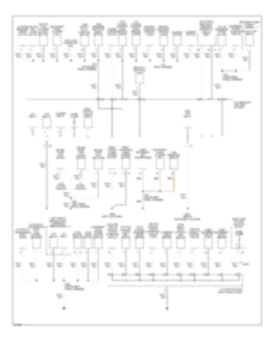
POWER DISTRIBUTION
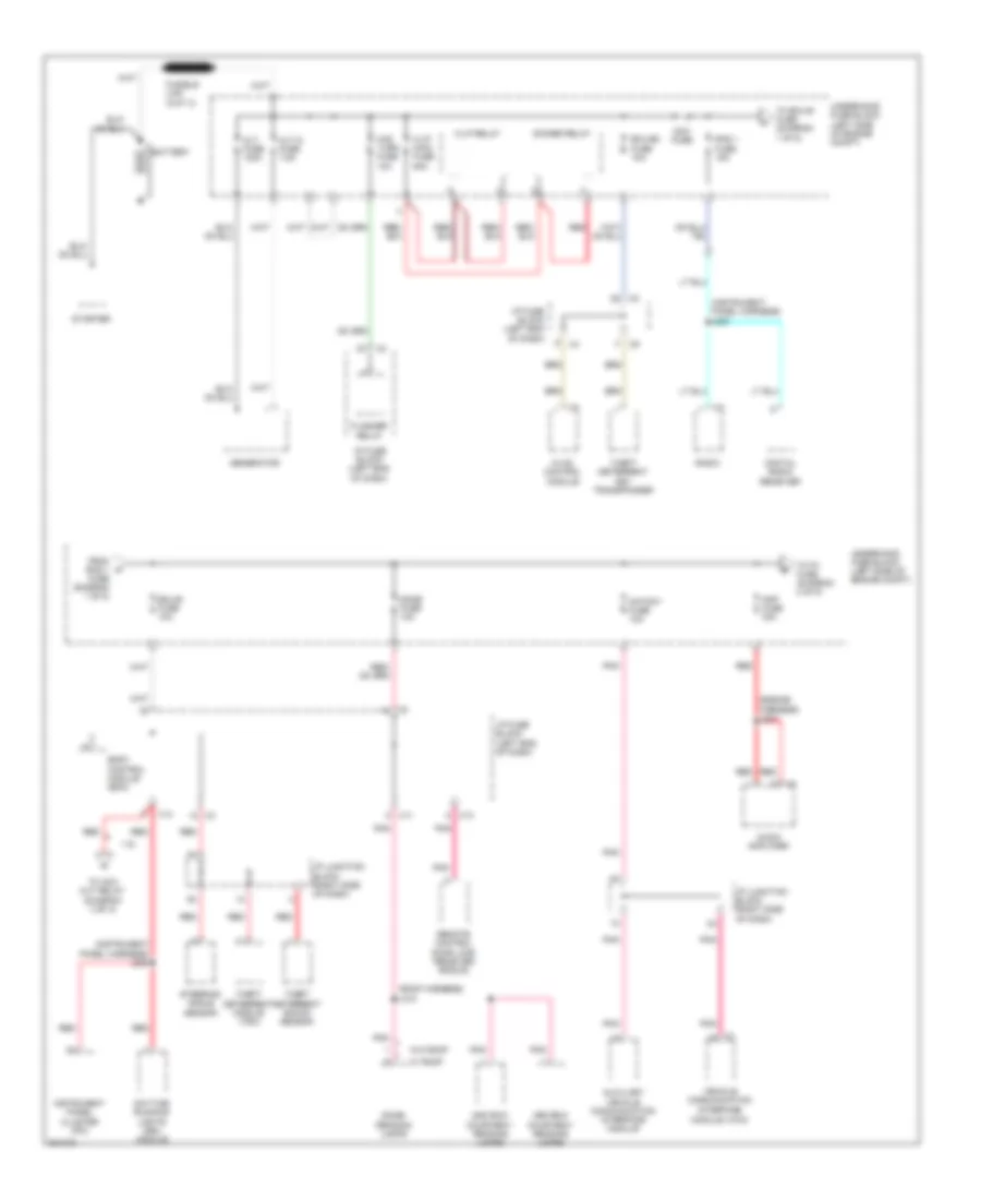
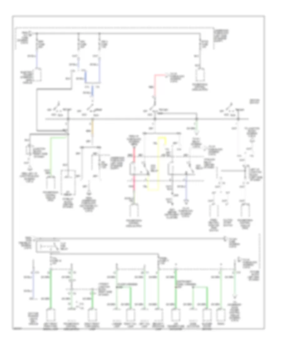
Power Distribution Wiring Diagram (1 of 5) for Pontiac Vibe 2010
List of elements for Power Distribution Wiring Diagram (1 of 5) for Pontiac Vibe 2010:
- (engine harness) j227
- (instrument panel harness) j200
- (instrument panel harness) j230
- (roof harness) j310
- 1.8l
- 2nd row courtesy/ reading lamps
- 3rd row courtesy/ reading lamps
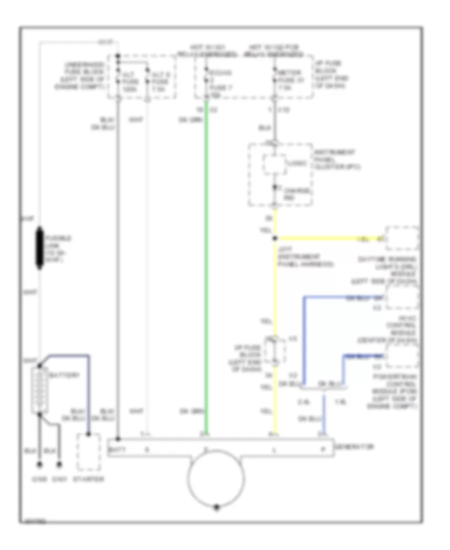
- Alt fuse 120a
- Alt s fuse 7.5a
- Amp fuse 30a
- Audio amplifier
- Auxiliary vehicle communication interface module
- Battery
- Body control module (bcm)
- Daytime running lights (drl) module
- Dcc fuse
- Digital radio receiver
- Dimmer relay
- Dome fuse 10a
- Dome/ reading lamps
- Ecu-b fuse 10a
- Ecu-b2 fuse 10a
- Flasher relay
- From rad 1 a
- Fuse (diagram 1 of 5)
- Generator
- H-lp main fuse 50a
- H-lp relay
- Haz turn fuse 10a
- Hvac control module
- I/p fuse block (left end of dash)
- I/p junction block (right side of dash)
- Instrument panel cluster (ipc)
- Mayday fuse 10a
- Module (vcim)
- Pnk
- Rad 1 fuse 15a
- Radio
- Red
- Remote control door lock receiver (rcdlr)
- Starter
- Steering angle sensor
- Theft deterrent key transponder
- Theft deterrent module (tdm)
- Theft deterrent shock sensor
- To acc cut relay (diagram 3 of 5)
- To ecu-b fuse (diagram 1 of 5)
- To p/i fuse (diagram 2 of 5)
- Underhood fuse block (left side of engine compt)
- Vehicle communication interface
- W/ roof
- W/o roof
- X11
- X13
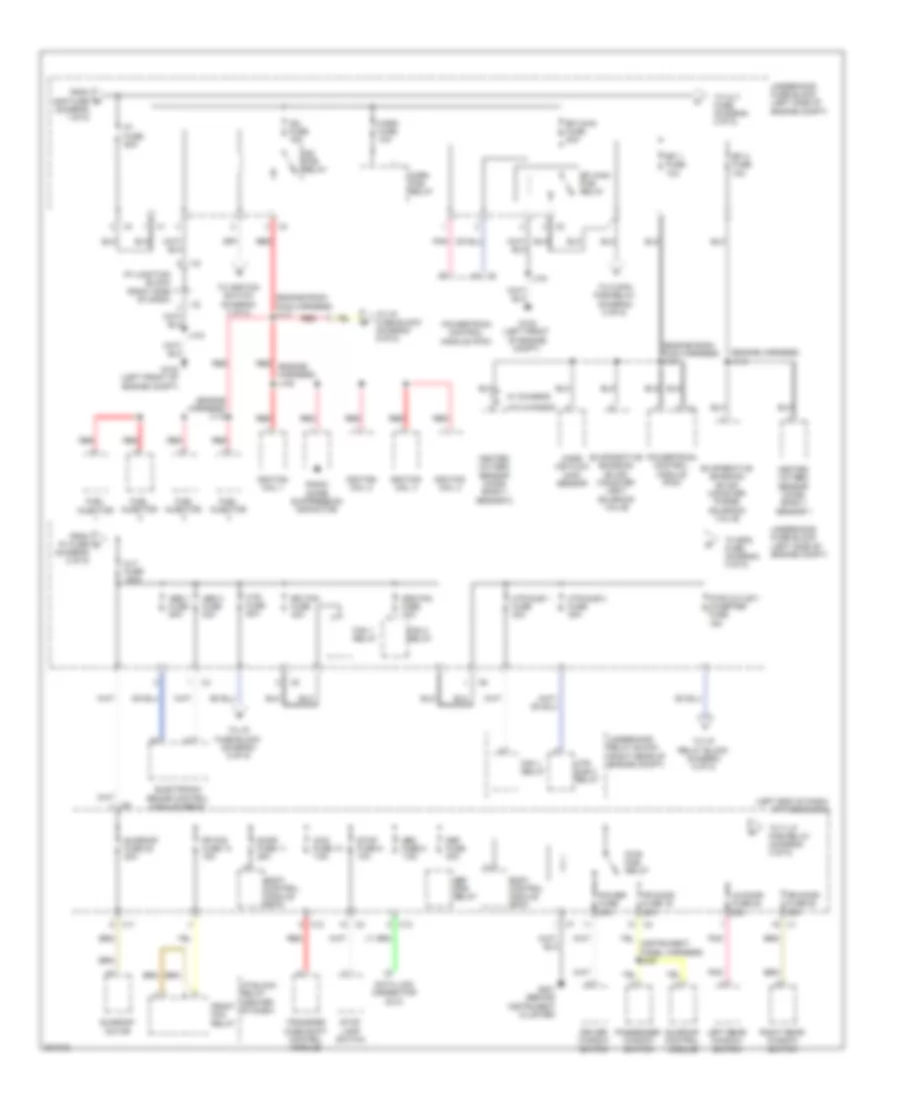
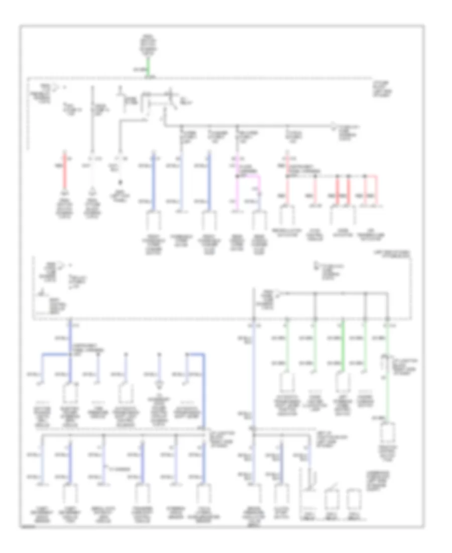
Power Distribution Wiring Diagram (2 of 5) for Pontiac Vibe 2010
List of elements for Power Distribution Wiring Diagram (2 of 5) for Pontiac Vibe 2010:
- (diagram 1 of 5)
- (diagram 2 of 5)
- (engine harness) j112
- (engine harness) j114
- (engine room main harness) j101
- (engine room main harness) j117
- (left end of dash) i/p fuse block
- 4wd fuse 13 7.5a
- Abs 1 fuse 50a
- Abs 3 fuse 30a
- Alt fuse 120a
- Body control module (bcm)
- Cds fan fuse 30a
- Data link connector (dlc)
- Def fuse 30a
- Def pcb relay
- Door fuse 11 25a
- Driver window switch
- Efi 1 fuse 10a
- Efi 2 fuse 10a
- Efi main fuse 20a
- Efi main pcb relay
- Electronic brake control module (ebcm)
- Evaporative emission (evap) canister purge solenoid valve
- Evaporative emission (evap) canister vent solenoid valve
- Fan 1 relay
- Fan 3 relay
- Fr door fuse 19 20a
- Fr fog fuse 14 15a
- From amp fuse b
- From p/i fuse c
- Front fog relay
- Fuel injector
- G102 (left front of engine compt)
- G201 (behind instrument cluster)
- Heated oxygen sensor (ho2s) bank 1 sensor 1
- Heated oxygen sensor (ho2s) bank 1 sensor 2
- Horn fuse 10a
- Horn pcb relay
- Htr fuse 50a
- Htr sub 1 fuse 30a
- Htr sub 3 fuse 30a
- Htr sub 3 relay
- I/p block relay (center of dash)
- I/p junction block (right side of dash)
- Ig2 fuse 15a
- Ig2 pcb relay
- Ignition coil 1
- Ignition coil 2
- Ignition coil 3
- Ignition coil 4
- J104
- Left rear window switch
- Lr door fuse 20 20a
- Mass air flow (maf) sensor
- Obd fuse 8 7.5a
- P/i fuse 50a
- Passenger window switch
- Pnk
- Power fuse 30a
- Powertrain control module (pcm)
- Pwr outlet/ inverter fuse 15a
- Pwr pcb relay
- Radio noise suppression capacitor
- Rdi fan fuse 40a
- Red
- Red (engine harness) j108
- Right rear window switch
- Rr door fuse 20 20a
- Stop fuse 9 10a
- Stop lamp switch
- Sunroof control module
- Sunroof fuse 22 20a
- Sunroof motor
- To alt fuse (diagram 2 of 5)
- To c/opn pcb relay (diagram 5 of 5)
- To eps fuse (diagram 3 of 5)
- To i/p fuse block (diagram 5 of 5)
- To i/p relay block (diagram 5 of 5)
- To ignition switch (diagram 3 of 5)
- To t-lp pcb relay (diagram 3 of 5)
- Transfer case shift control module
- Underhood fuse block (left side of engine compt)
- Underhood relay block (right rear of engine compt)
- W/ chassis
- W/o chassis
- X11
- X12
- X13
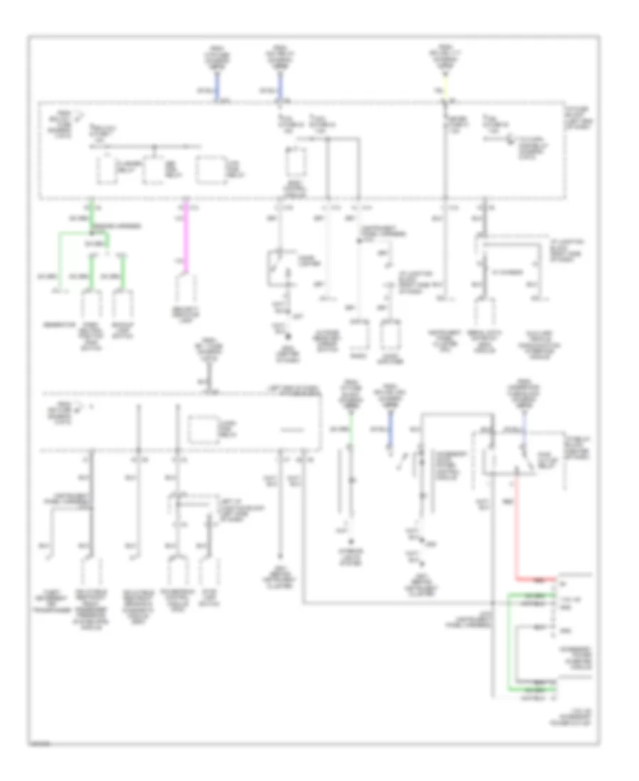
Power Distribution Wiring Diagram (3 of 5) for Pontiac Vibe 2010
List of elements for Power Distribution Wiring Diagram (3 of 5) for Pontiac Vibe 2010:
- (floor harness) j302
- (instrument panel harness) j222
- 1.8l
- 2.4l
- A/t
- Acc
- Acc cut relay
- Acc relay
- Air temperature actuator
- Am2 2 fuse 7.5a
- Am2 fuse 30a
- Blower motor switch
- Clutch start switch
- Daytime running lights (drl) module
- Electric power steering (eps) module
- Esp fuse 60a
- Etcs fuse 10a
- From alt d
- From i/p fuse block (diagram 1 of 5)
- From left i/p junction block (diagram 3 of 5)
- From pwr k
- From underhood fuse block (ig2 pcb relay) (diagram 2 of 5)
- Fuse (diagram 2 of 5)
- G201 (behind instrument cluster)
- I/p block relay (center of dash)
- I/p fuse block (left end of dash)
- I/p relay block (center of dash)
- I/p right junction block (right side of dash)
- Ig2 fuse 7.5a
- Ignition switch
- J205
- Junction block (right side of dash)
- Left front park/turn signal lamp
- Left i/p junction block (left side of dash)
- Left tail lamp
- License lamp
- M/t
- Mode actuator
- Off
- Panel fuse 17 7.5a
- Park/ neutral position (pnp) siwtch
- Pcb relay (diagram 2 of 5)
- Pnk
- Powertrain control module (pcm)
- Radio
- Red
- Right front turn signal lamp
- Right tail lamp
- Run
- Security indicator lamp
- St relay
- Start
- T-lp pcb relay
- Tail fuse 16 10a
- To accessory ac/dc power control module (diagram 5 of 5)
- To am1 fuse (diagram 4 of 5)
- To i/p fuse block (diagram 4 of 5)
- To i/p fuse block (diagram 5 of 5)
- To ig 1 relay (diagram 4 of 5)
- To junction block (diagram 3 of 5)
- Underhood fuse block (left side of engine compt)
- X13
- X15
Power Distribution Wiring Diagram (4 of 5) for Pontiac Vibe 2010
List of elements for Power Distribution Wiring Diagram (4 of 5) for Pontiac Vibe 2010:
- (instrument panel harness) j203
- (left end of dash) i/p fuse block
- Acc-b fuse 12 25a
- Air temperature actuator
- Am1 fuse 15 7.5a
- Automatic transmission shift lever
- Automatic transmission shift lever position indicator
- Automatic transmission shift lock control solenoid
- Body control module (bcm)
- Brake pressure modulator valve (bpmv)
- Cigar lighter illumination lamp
- Clutch start switch
- Daytime running lights (drl) module
- Ecu-ig 1 fuse 6 10a
- Electric power steering (eps) module
- Fan 1 relay
- Fan 2 relay
- Fan 3 relay
- From htr-ig m
- From i/p fuse block (diagram 3 of 5)
- From ignition switch (diagram 3 of 5)
- From panel n
- From t-lp l
- Front windshield washer fluid pump
- Front windshield wiper/ washer switch
- Fuse (diagram 3 of 5)
- Fuse (diagram 4 of 5)
- G200 (left kick panel)
- Hazard warning switch
- Htr-ig fuse 2 10a
- Hvac control module
- I/p fuse block (left end of dash)
- I/p junction block (right side of dash)
- Ig 1 relay
- Left i/p junction block (left side of dash)
- Left steering wheel control switch
- Mode actuator
- Noise filter
- Pcb relay (diagram 3 of 5)
- Rear window washer fluid pump
- Rear window wiper motor
- Recirculation actuator
- Red
- Red (instrument panel harness) j214
- Rr wiper fuse 4 15a
- Serial data gateway (sdg) module
- Steering angle sensor
- Theft deterrent module (tdm)
- Theft deterrent shock sensor
- Tire pressure module
- To accessory ac/dc power control module (diagram 5 of 5)
- To ecu-ig 1 fuse (diagram 4 of 5)
- To ecu-ig 2 fuse (diagram 5 of 5)
- Traction control switch (tcs)
- Transfer case shift control module
- Underhood fuse block (left side of engine compt)
- W/ chassis
- Washer fuse 5 15a
- Windshield wiper motor
- Wiper fuse 3 25a
- X12
- X13
- X14
- X15
- Yaw & lateral accelerometer sensor
Power Distribution Wiring Diagram (5 of 5) for Pontiac Vibe 2010
List of elements for Power Distribution Wiring Diagram (5 of 5) for Pontiac Vibe 2010:
- (diagram 5 of 5)
- (engine harness) j116
- (instrument panel harness) j224
- (instrument panel harness) j232
- (left end of dash) i/p fuse block
- 110v ac
- 110v ac accessory power outlet
- A/t
- Acc fuse 24 7.5a
- Accessory ac/dc power control module
- Accessory power inverter module
- Audio amplifier
- Auxiliary vehicle communication interface module
- Backup lamp switch
- Body control module
- C/opn pcb relay
- Cig fuse 23 15a
- Cigar lighter
- Def pcb relay
- Ecu-ig 2 fuse 7 10a
- Flasher relay
- From acc relay (diagram 3 of 5)
- From ecu-ig 1 o
- From efi 1 fuse (diagram 2 of 5)
- From htr fuse (diagram 2 of 5)
- From i/p fuse block (diagram 3 of 5)
- From ign fuse s
- From splice j117 (diagram 2 of 5)
- From splice j203 (diagram 4 of 5)
- From underhood fuse block (diagram 2 of 5)
- Fuse (diagram 4 of 5)
- G201 (behind instrument cluster)
- G204 (center of dash)
- Generator
- Gnd
- Htr pcb relay
- I/p fuse block (left end of dash)
- I/p junction block (right side of dash)
- I/p relay block (center of dash)
- Ign fuse 30 7.5a
- Inflatable restraint front passenger presence system (pps) module
- Inflatable restraint sensing & diagnostic module (sdm)
- Instrument panel cluster (ipc)
- Interior lights system
- J205
- J218 (instrument panel harness)
- J237
- Left i/p junction block (left side of dash)
- M/t
- Meter fuse 31 7.5a
- Outside rearview mirror switch
- Park/ neutral position (pnp) switch
- Powertrain control module (pcm)
- Pwr outlet relay
- Radio
- Red
- Security indicator lamp
- Serial data gateway (sdg) module
- Stop lamp switch
- Theft deterrent key transponder
- To c/opn pcb relay (diagram 5 of 5)
- W/ chassis
- X10
- X12
- X13
- X14
- X15
POWER DOOR LOCKS
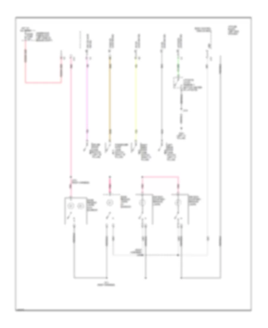
Power Door Locks Wiring Diagram (1 of 2) for Pontiac Vibe 2010
List of elements for Power Door Locks Wiring Diagram (1 of 2) for Pontiac Vibe 2010:
- (left end of dash) i/p fuse block
- Actuator sig
- Ajar sw rr door
- Auxiliary vehicle communication interface module
- Batt(+) volt
- Body control module (bcm)
- Dome fuse 10a
- Door fuse 11 25 a
- Driver door jamb switch (left "b" pillar)
- Driver door lock actuator (rear of left front door)
- Driver door lock switch
- Driver door lock window switch
- Drv dr key sw unlk sig
- Drv dr lk position sw in
- Enable sig
- G200 (left kick panel)
- G203 (right kick panel)
- G205 (right "c" pillar)
- Ground
- Hot at all times
- J500
- J600
- Jamb sw lr door
- Key cylinder switch
- Left rear door jamb switch (left "c" pillar)
- Lock detection switch
- Lock sw sig
- Passenger door ajar sw
- Passenger door jamb switch (right "b" pillar)
- Passenger door key sw
- Passenger door lock actuator (rear of right front door)
- Passenger door lock switch
- Pnk
- Position sw in pass dr lk
- Red
- Remote control door lock receiver (rcdlr) (right "c" pillar)
- Rf dr lk
- Right rear door jamb switch (right "c" pillar)
- Serial data
- Un lock sw sig
- Underhood fuse block (left side of engine compt)
- Unlk ctrl drv dr lk mtr
- W/ power windows
- W/o power windows
- X13
Power Door Locks Wiring Diagram (2 of 2) for Pontiac Vibe 2010
List of elements for Power Door Locks Wiring Diagram (2 of 2) for Pontiac Vibe 2010:
- (floor harness) j303
- (floor harness) j306
- B +
- Batt positive vol
- Body control module (bcm)
- Computer data lines system
- Data communication (+)
- Data communication (-)
- Data communication (-) data communication (+)
- Ecu-b fuse 10 a
- Ecu-ig fuse 6 10 a
- G200 (left kick panel)
- G201 (behind instrument cluster)
- G206 (right "c" pillar)
- G301 (left "c" pillar)
- G302 (left "c" pillar)
- Glass brk asw sens sig
- Ground
- Hot at all times
- Hot w/ ig 1 relay energized
- I/p fuse block (left end of dash)
- I/p fuse block (left end of dash) x7
- I/p junction block (right side of dash)
- Ignition key alarm switch (at ignition switch)
- Ignition volt
- Ignition voltage
- J203
- J233 (instrument panel harness)
- J235 (instrument panel harness)
- J312
- Key switch signal
- Left rear door lock actuator
- Left rear door lock actuator (rear of left rear door)
- Liftgate latch assembly (bottom center of liftgate)
- Microphone sig (+)
- Microphone sig (-)
- Motor unlock ctrl driver door lock
- Red
- Right rear door lock actuator (rear of right rear door)
- Rr dr lk position sw in
- Security ind lp sply volt
- Security indicator lamp
- Shock sens sig
- Theft deterrent module (tdm) (right side of dash)
- Theft deterrent shock sensor (right side of dash)
- Theft deterrent shock sensor microphone (left end of dash)
- Underhood fuse block (left side of engine compt)
- X13
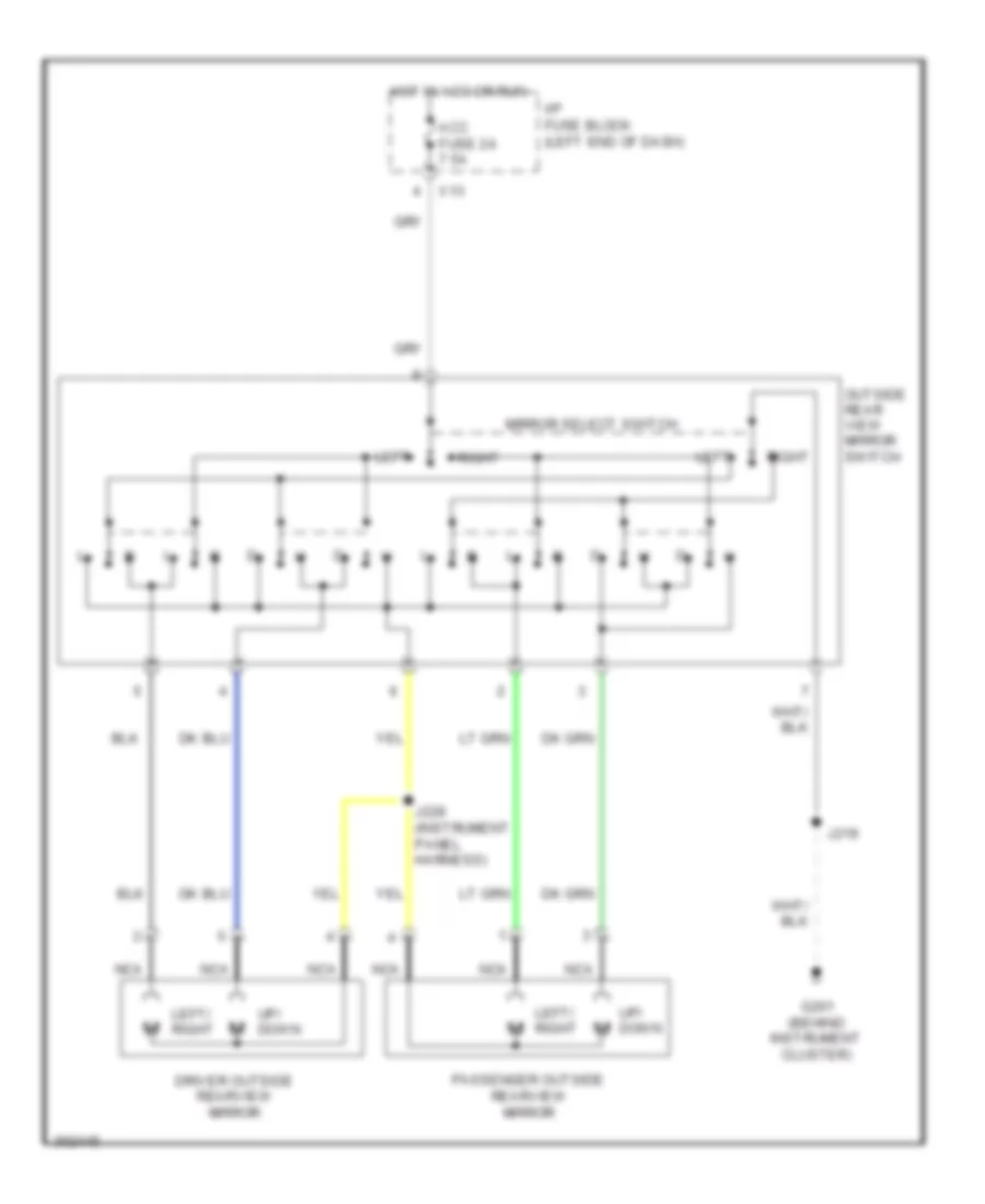
POWER MIRRORS
Power Mirrors Wiring Diagram for Pontiac Vibe 2010
List of elements for Power Mirrors Wiring Diagram for Pontiac Vibe 2010:
- Acc fuse 24 7.5a
- Driver outside rearview mirror
- G201 (behind instrument cluster)
- Hot in acc or run
- I/p fuse block (left end of dash)
- J219
- J228 (instrument panel harness)
- Left
- Left/ right
- Mirror select switch
- Nca
- Outside rear view mirror switch
- Passenger outside rearview mirror
- Right
- Up/ down
- X13
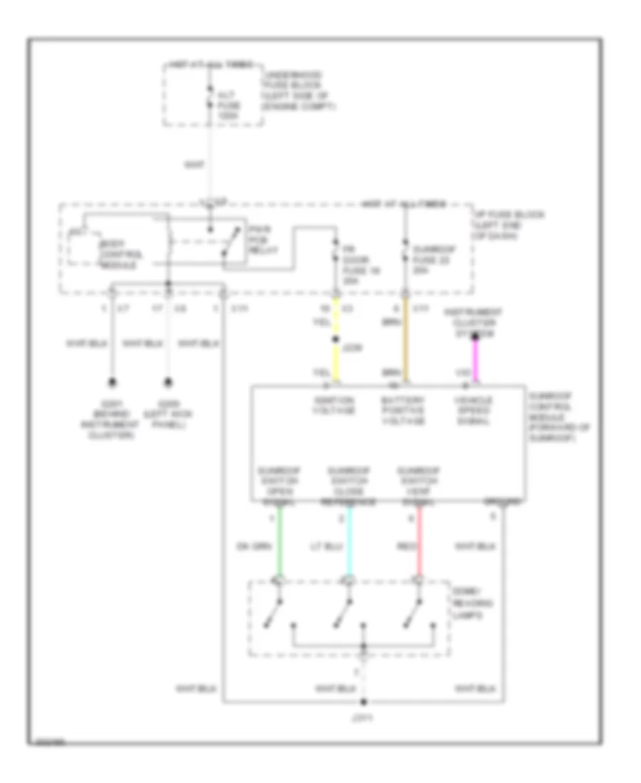
POWER TOP/SUNROOF
Power Top/Sunroof Wiring Diagram for Pontiac Vibe 2010
List of elements for Power Top/Sunroof Wiring Diagram for Pontiac Vibe 2010:
- Alt fuse 120a
- Battery positive voltage
- Body control module
- Dome/
- Fr door fuse 19 20a
- G200 (left kick panel)
- G201 (behind instrument cluster)
- Ground
- Hot at all times
- I/p fuse block (left end of dash)
- Ignition voltage
- Instrument cluster system
- J239
- J311
- Lamps
- Pwr pcb relay
- Reading
- Red
- Sunroof control module (forward of sunroof)
- Sunroof fuse 22 20a
- Sunroof switch close reference
- Sunroof switch open signal
- Sunroof switch vent signal
- Underhood fuse block (left side of engine compt)
- Vehicle speed signal
- X11
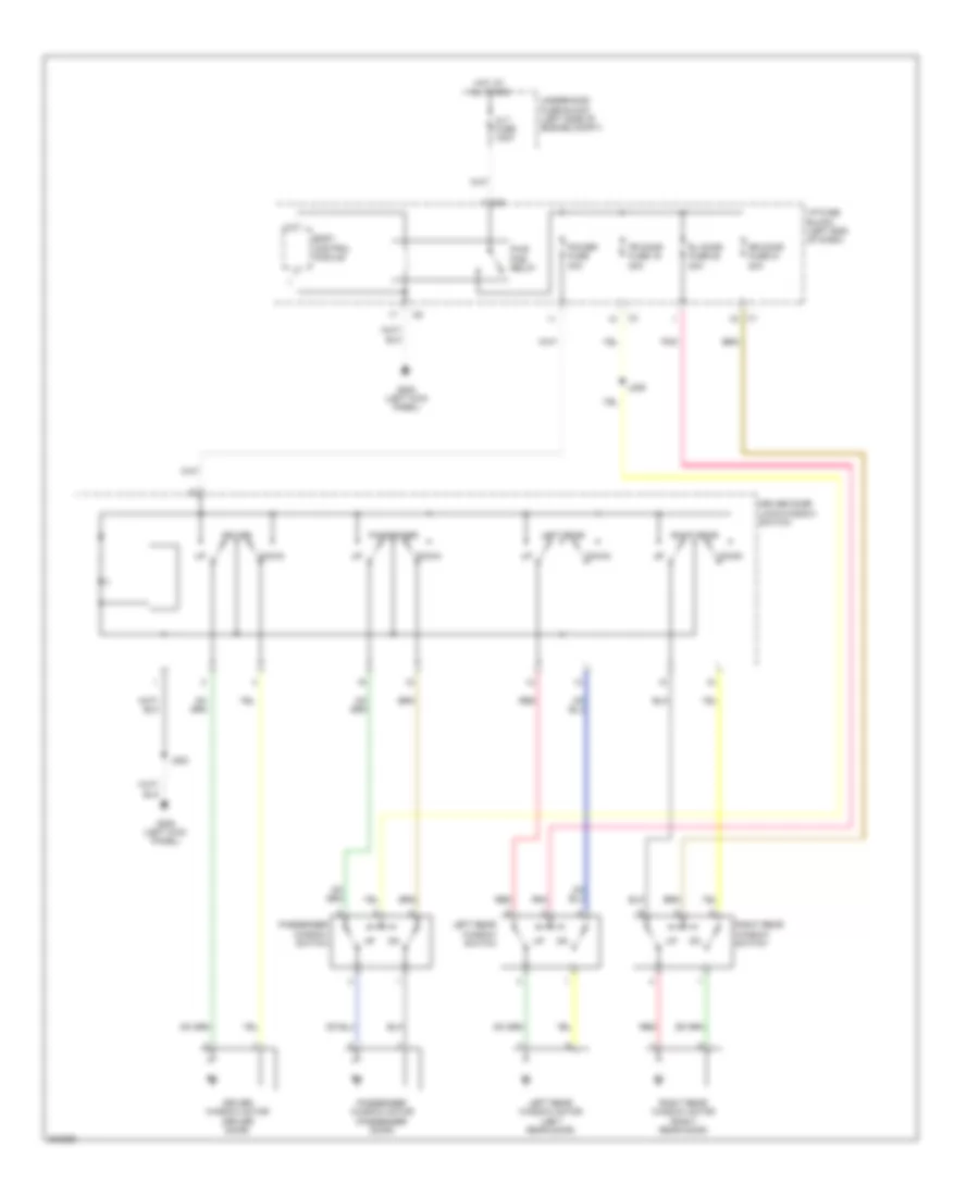
POWER WINDOWS
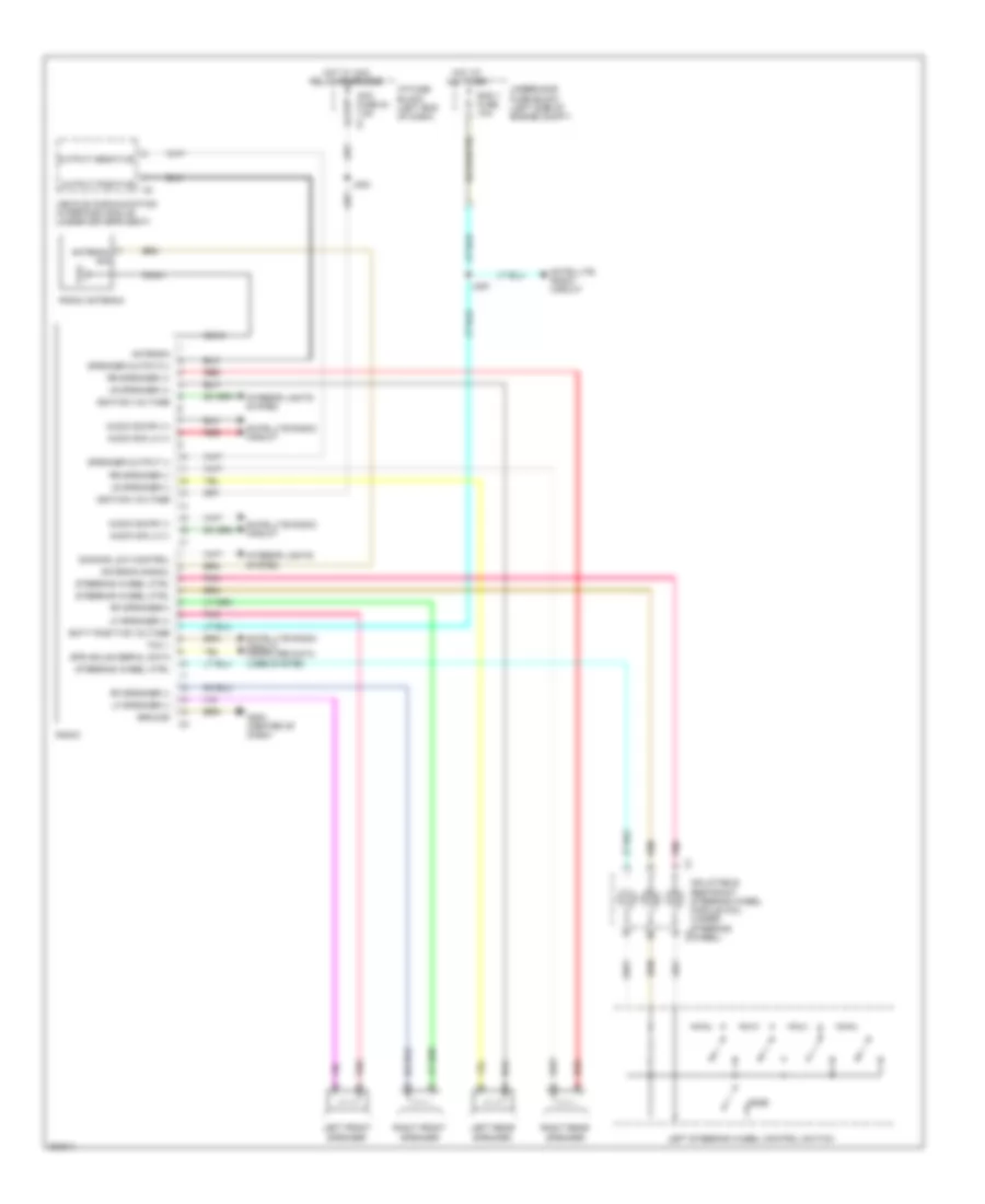
Power Windows Wiring Diagram for Pontiac Vibe 2010
List of elements for Power Windows Wiring Diagram for Pontiac Vibe 2010:
- Alt fuse 120a
- Body control module
- Down
- Driver
- Driver door lock/window switch
- Driver window motor (driver door)
- Fr door fuse 19 20a
- G200 (left kick panel)
- Hot at all times
- I/p fuse block (left end of dash)
- J239
- J500
- Left rear
- Left rear window motor (left rear door)
- Left rear window switch
- Passenger
- Passenger window motor (passenger door)
- Passenger window switch
- Pnk
- Power fuse 30a
- Pwr pcb relay
- Red
- Right rear
- Right rear window motor (right rear door)
- Right rear window switch
- Rl door fuse 20 20a
- Rr door fuse 21 20a
- Underhood fuse block (left side of engine compt)
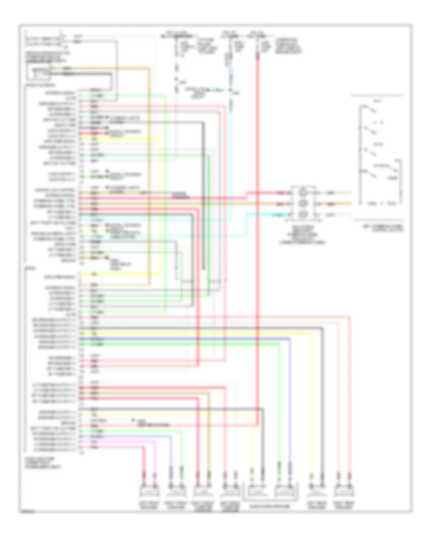
RADIO
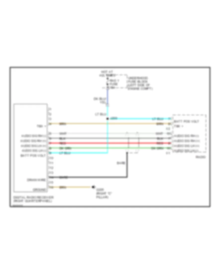
Radio Wiring Diagram, with Amplifier for Pontiac Vibe 2010
List of elements for Radio Wiring Diagram, with Amplifier for Pontiac Vibe 2010:
- (engine harness)
- Acc fuse 24 7.5a x4
- Amp fuse 30a
- Amplifier signal
- Antenna sig
- Antenna signal
- Audio amplifier (under front passenger's seat)
- Audio sig lh (+)
- Audio sig lh (-)
- Audio sig rh (+)
- Audio sig rh (-)
- Bare
- Batt positive voltage
- Coax
- Dimming low control
- Drain wire
- G202 (center of dash)
- G204 (center of dash)
- Ground
- Hot at all times
- Hot w/ acc relay energized
- I/p fuse block (left end of dash)
- Ignition voltage
- Inflatable restraint steering wheel module coil (under steering wheel)
- Interior lights system
- J200
- J224
- J227
- Left front speaker
- Left front tweeter speaker
- Left rear speaker
- Left steering wheel control switch
- Lf speaker output (+)
- Lf speaker output (-)
- Lf tweeter (+)
- Lf tweeter (-)
- Lf tweeter output (+)
- Lf tweeter output (-)
- Lr speaker (+)
- Lr speaker (-)
- Lr speaker output (+)
- Lr speaker output (-)
- Mode
- Mute
- Output positive
- Pnk
- Rad 1 fuse 15a
- Radio
- Radio antenna
- Red
- Rf speaker output (+)
- Rf speaker output (-)
- Rf tweeter (+)
- Rf tweeter (-)
- Rf tweeter output (+)
- Rf tweeter output (-)
- Right front speaker
- Right front tweeter speaker
- Right rear speaker
- Rr speaker (+)
- Rr speaker (-)
- Rr speaker output (+)
- Rr speaker output (-)
- Satellite radio circuit
- Satellite radio circuit computer data lines system
- Spd gmlan serial data
- Speaker output (+)
- Speaker output (-)
- Speaker output(+)
- Steering wheel ctrl
- Subwoofer speaker
- Tmx +
- Underhood fuse block (left side of engine compt)
- Vehicle communication interface module (under driver's seat)
Radio Wiring Diagram, without Amplifier for Pontiac Vibe 2010
List of elements for Radio Wiring Diagram, without Amplifier for Pontiac Vibe 2010:
- Acc fuse 24 7.5a x4
- Antenna
- Antenna sig
- Antenna signal
- Audio sig lh (+)
- Audio sig lh (-)
- Audio sig rh (+)
- Audio sig rh (-)
- Batt positive voltage
- Coax
- Dimming low control
- G202 (center of dash)
- Ground
- Hot at all times
- Hot w/ acc relay energized
- I/p fuse block (left end of dash)
- Ignition voltage
- Inflatable restraint steering wheel module coil (under steering wheel)
- Interior lights system
- J200
- J224
- Left front speaker
- Left rear speaker
- Left steering wheel control switch
- Lf speaker (+)
- Lf speaker (-)
- Lr speaker (+)
- Lr speaker (-)
- Mode
- Output positive
- Pnk
- Rad 1 fuse 15a
- Radio
- Radio antenna
- Red
- Rf speaker (-)
- Rf speaker(+)
- Right front speaker
- Right rear speaker
- Rr speaker (+)
- Rr speaker (-)
- Satellite radio circuit
- Satellite radio circuit computer data lines system
- Spd gmlan serial data
- Speaker output (-)
- Speaker output(+)
- Steering wheel ctrl
- Tmx +
- Underhood fuse block (left side of engine compt)
- Vehicle communication interface module (under driver's seat)
Satellite Radio Wiring Diagram for Pontiac Vibe 2010
List of elements for Satellite Radio Wiring Diagram for Pontiac Vibe 2010:
- Audio sig lh (+)
- Audio sig lh (-)
- Audio sig rh (+)
- Audio sig rh (-)
- Bare
- Batt pos volt
- Digital radio receiver (right quarterpanel)
- Drain wire
- G205 (right "c" pillar)
- Ground
- Hot at all times
- J200
- Rad 1 fuse 15a
- Radio
- Red
- Tmx +
- Underhood fuse block (left side of engine compt)
SHIFT INTERLOCK
Shift Interlock Wiring Diagram for Pontiac Vibe 2010
List of elements for Shift Interlock Wiring Diagram for Pontiac Vibe 2010:
- (behind instrument cluster) g201
- 4 speed a/t
- 5 speed a/t
- Am1 fuse 7.5a
- Automatic transmission shift lock control solenoid (under center console)
- Computer data lines system
- Ecu-ig 1 fuse 6 10a
- Ecu-ig 2 fuse 7 10a
- G200 (left kick panel)
- Gnd
- Hi spd gmlan serial data bus+
- Hi spd gmlan serial data bus-
- Hot at all times
- Hot w/ ig1 relay energized
- I/p fuse block (left end of dash)
- Ign lk cyl sol ctrl
- Ign sw sig st
- Ign vol
- Ignition lock cylinder control solenoid (at ignition switch)
- Ignition switch
- J116
- J203
- J205
- J219
- Left i/p junction block (left side of dash)
- Park/ neutral position (pnp) switch (on trans- mission)
- Pnp sw neutral sig
- Pnp sw park sig
- Powertrain control module (pcm) (left side of engine compt)
- Red
- Stop fuse 9 10a
- Stop lamp switch (left side of dash)
- Stp lp sw sig
- X13
STARTING/CHARGING
Charging Wiring Diagram for Pontiac Vibe 2010
List of elements for Charging Wiring Diagram for Pontiac Vibe 2010:
- 1.8l
- 2.4l
- Alt fuse 120a
- Alt s fuse 7.5a
- Batt
- Battery
- Charge ind
- Daytime running lights (drl) module (left side of dash)
- Ecu-ig fuse 7 10a
- G100
- G101
- Generator
- Hot w/ ig1 relay energized
- Hot w/ ig2 pcb relay energized
- Hvac control module (center of dash)
- I/p fuse block (left end of dash)
- Instrument panel cluster (ipc)
- J217 (instrument panel harness)
- Logic
- Meter fuse 31 7.5a
- Powertrain control module (pcm) (left side of engine compt)
- Starter
- Underhood fuse block (left side of engine compt)
- X12
Starting Wiring Diagram for Pontiac Vibe 2010
List of elements for Starting Wiring Diagram for Pontiac Vibe 2010:
- 1.8l
- 2.4l
- Acc
- Am1 fuse 15 7.5a
- Am2 2 fuse 7.5a
- Am2 fuse 30a
- Automatic transmission
- Battery
- Clutch start switch (left side of dash)
- G100
- G101
- G201 (behind instrument cluster)
- Hot w/ t-lp pcb relay energized
- I/p fuse block (left end of dash)
- I/p relay block (center of dash)
- Ignition switch
- J205
- J211 (instrument panel harness)
- Junction block (right side of dash)
- Left i/p junction block (left side of dash)
- Manual transmission
- Off
- Park/neutral position (pnp) switch (on transmission)
- Powertrain control module (pcm) (left side of engine compt)
- Red
- Run
- St relay
- Start
- Starter
- Underhood fuse block (left side of engine compt)
SUPPLEMENTAL RESTRAINTS
Supplemental Restraints Wiring Diagram (1 of 3) for Pontiac Vibe 2010
List of elements for Supplemental Restraints Wiring Diagram (1 of 3) for Pontiac Vibe 2010:
- Computer data lines system
- Drv hi ctrl
- Drv lo ctrl
- Ecu-ig no 2 fuse 7 10a
- G200 (left kick panel)
- G201 (behind instrument cluster)
- Gnd
- Hi ctrl
- Hot w/ ig 1 relay energized
- Hot w/ ig 2 pcb relay energized
- I/p fuse block (left end of dash)
- Ign fuse 30 7.5a
- Ign voltage
- Inflatable restraint sensing & diagnostic module (sdm) (under center console)
- J232
- Left inflatable restraint side impact module (left side of driver's seat back)
- Lf hi ctrl
- Lf lo ctrl
- Lh hi ctrl
- Lh lo ctrl
- Lh sig
- Lo ctrl
- Lo ref
- Lo spd serial data
- Lr hi ctrl
- Lr lo ctrl
- Meter fuse 31 7.5a
- Pass hi ctrl
- Pass lo ctrl
- Pass out
- Red
- Rh hi ctrl
- Rh lo ctrl
- Rh rr hi ctrl
- Right inflatable restraint roof rail module (right side of roof)
- Right inflatable restraint side impact module (right side of front passenger's seat back)
- Right inflatable restraint side impact sensor (sis) (right "b" pillar)
- Right rear inflatable restraint side impact sensor (sis) (right "c" pillar)
- Rr lo ctrl
- Serial data (+)
- Serial data (-)
- Serial data bus (+)
- Serial data bus (-)
- Shorting bar
- Sig
- X12
- X13
Supplemental Restraints Wiring Diagram (2 of 3) for Pontiac Vibe 2010
List of elements for Supplemental Restraints Wiring Diagram (2 of 3) for Pontiac Vibe 2010:
- Air bag ind
- Computer data lines system
- Driver inflatable restraint seat position sensor (sps)
- Driver seat belt buckle (driver's seat belt buckle assembly)
- Driver seat belt switch
- Inflatable restraint i/p module (right side of dash)
- Inflatable restraint steering wheel module (in steering wheel)
- Inflatable restraint steering wheel module coil (under steering wheel)
- Instrument panel cluster (ipc)
- Left inflatable restraint roof rail module (left side of roof)
- Left inflatable restraint side impact sensor (sis) (left "b" pillar)
- Left rear inflatable restraint side impact sensor (sis) (left "c" pillar)
- Logic
- Nca
- Red
- Seat belt ind
- Shorting bar
Supplemental Restraints Wiring Diagram (3 of 3) for Pontiac Vibe 2010
List of elements for Supplemental Restraints Wiring Diagram (3 of 3) for Pontiac Vibe 2010:
- B+ volt
- Computer data lines system
- Driver seat belt pretensioner (base of left "b" pillar)
- G205 (right "c" pillar)
- Gnd
- Inflatable restraint front passenger presence system (pps) module (under front passenger's seat)
- Inflatable restraint front passenger presence system (pps) sensor (under front passenger's seat)
- Left inflatable restraint front end sensor (left front of engine compt)
- Lo spd serial data
- Low ref
- Nca
- Pass gnd
- Pass sig
- Pass volt
- Passenger inflatable restraint seat belt tension sensor (base of right "b" pillar)
- Passenger inflatable restraint seat position sensor (under front passenger's seat)
- Passenger seat belt buckle (front passenger's seat belt buckle assembly)
- Passenger seat belt pretensioner (base of right "b" pillar)
- Passenger seat belt switch
- Pnk
- Pps sig
- Pps volt
- Red
- Rh low ref
- Rh sig
- Right inflatable restraint front end sensor (right front of engine compt)
- Security indicator lamp
- Serial data +
- Serial data -
- Shorting bar
TRANSMISSION
1.8L VIN 8
1.8L VIN 8, A/T Wiring Diagram for Pontiac Vibe 2010
List of elements for 1.8L VIN 8, A/T Wiring Diagram for Pontiac Vibe 2010:
- (engine harness) j111
- (engine harness) j226
- Automatic transmission fluid temperature (tft) sensor
- Automatic transmission input shaft speed (iss) sensor (on transmission)
- Automatic transmission shift lever position indicator
- Backup lamp sw sig
- Computer data lines system
- Ecu-ig 2 fuse 7 10a
- Etcs fuse 10a
- Exterior lights system
- G102 (left front of engine compt)
- Gmlan serial data bus+
- Gmlan serial data bus-
- Ground
- High signal
- Hot at all times
- Hot w/ ign 1 relay energized
- I/p fuse block (left end of dash)
- J104
- J116
- Low reference
- Low signal
- Park/neutral position (pnp) switch (on transmission)
- Pnk
- Pnp sw drive sig
- Pnp sw neutral sig
- Pnp sw second sig
- Pnp switch low sig
- Pnp switch park sig
- Powertrain control module (pcm) (left side of engine compt)
- Red
- S1 control
- S2 control
- Shift lock relay ctrl
- Shift solenoid valve (ssv) s1
- Shift solenoid valve (ssv) s2
- Shift solenoid valve (ssv) slt
- Shift solenoid valve (ssv) slu
- Shift solenoid valve (ssv) st
- Slt high control
- Slt low control
- Slu high control
- Slu low control
- Tft sensor signal
- Transmission connector
- Underhood fuse block (left side of engine compt)
1.8L VIN 8, Transfer Case Wiring Diagram for Pontiac Vibe 2010
List of elements for 1.8L VIN 8, Transfer Case Wiring Diagram for Pontiac Vibe 2010:
- 4wd fuse 13 7.5a
- 4wd ind
- Bare
- Bus+
- Bus-
- Clutch ctrl high
- Clutch ctrl low
- Computer data lines system
- Display
- Drain wire
- Ecu-ig 1 fuse 6 10a
- G204 (center of dash)
- Ground
- Hot at all times
- Hot w/ ig1 relay energized
- I/p center junction block
- I/p fuse block (left end of dash)
- Ignition voltage
- Instrument panel cluster (ipc)
- J203
- Logic
- Meter fuse 31 7.5a
- Red
- Serial data bus +
- Serial data bus -
- Transfer case clutch coil (rear axle)
- Transfer case shift control module (right side of dash)
- X12
- X13
2.4L VIN 0
2.4L VIN 0, A/T Wiring Diagram, 4 Speed A/T for Pontiac Vibe 2010
List of elements for 2.4L VIN 0, A/T Wiring Diagram, 4 Speed A/T for Pontiac Vibe 2010:
- (engine harness) j111
- (engine harness) j226
- Automatic transmission fluid temperature (tft) sensor
- Automatic transmission input shaft speed (iss) sensor (on transmission)
- Automatic transmission output shaft speed (oss) sensor (on transmission)
- Automatic transmission shift lever
- Backup lamp sw sig
- Computer data lines system
- Ecu-ig 2 fuse 7 10a
- Etcs fuse 10a
- Exterior lights system
- G102 (left front of engine compt)
- Gmlan serial data bus+
- Gmlan serial data bus-
- Ground
- Hot at all times
- Hot w/ ign 1 relay energized
- I/p fuse block (left end of dash)
- Inp shaft spd high signal
- Inp shaft spd low signal
- J104
- J116
- Low reference
- Park/neutral position (pnp) switch (on transmission)
- Pnk
- Pnp sw drive sig
- Pnp sw neutral sig
- Pnp sw second sig
- Pnp switch low sig
- Pnp switch park sig
- Powertrain control module (pcm) (left side of engine compt)
- Red
- Shaft speed sen high sig
- Shaft speed sen low sig
- Shift lock relay ctrl
- Shift sol valve s4 ctrl
- Shift sol vlv dsl ctrl
- Shift sol vlv sl1 low ctrl
- Shift solenoid valve (ssv) dsl
- Shift solenoid valve (ssv) s4
- Shift solenoid valve (ssv) sl1
- Shift solenoid valve (ssv) sl2
- Shift solenoid valve (ssv) slt
- Sl1 high control
- Sl2 high control
- Sl2 low control
- Slt high control
- Slt low control
- Tft sensor signal
- Transmission connector
- Underhood fuse block (left side of engine compt)
2.4L VIN 0, A/T Wiring Diagram, 5 Speed A/T for Pontiac Vibe 2010
List of elements for 2.4L VIN 0, A/T Wiring Diagram, 5 Speed A/T for Pontiac Vibe 2010:
- (behind instrument cluster) g201
- (left front of engine compt) g102
- Automatic transmission fluid temperature (tft) sensor
- Automatic transmission input shaft speed (iss) sensor (on transmission)
- Automatic transmission output shaft speed (oss) sensor (on transmission)
- Automatic transmission shift lever
- Backup lamp sw sig
- Computer data lines system
- Ecu-ig 1 fuse 6 7.5a
- Ecu-ig 2 fuse 7 10a
- Etcs fuse 10a
- Exterior lights system
- Gmlan serial data bus+
- Gmlan serial data bus-
- Ground
- Hot at all times
- Hot w/ ign 1 relay energized
- I/p fuse block (left end of dash)
- Inp shaft spd high signal
- Inp shaft spd low signal
- J104
- J111 (engine harness)
- J116
- J203
- J205
- Low reference
- Park/neutral position (pnp) switch (on transmission)
- Pnk
- Pnp sw drive sig
- Pnp sw neutral sig
- Pnp switch low sig
- Pnp switch park sig
- Powertrain control module (pcm) (left side of engine compt)
- Red
- S-d
- Shaft speed sen high sig
- Shaft speed sen low sig
- Shift sol valve s4 ctrl
- Shift sol valve sr ctrl
- Shift sol vlv sl1 low ctrl
- Shift sol vlv sl3 high ctrl
- Shift sol vlv sl3 low ctrl
- Shift solenoid valve (ssv) dsl
- Shift solenoid valve (ssv) s4
- Shift solenoid valve (ssv) sl1
- Shift solenoid valve (ssv) sl2
- Shift solenoid valve (ssv) sl3
- Shift solenoid valve (ssv) slt
- Shift solenoid valve (ssv) sr
- Shift switch tap down sig
- Shift switch tap up sig
- Sl1 high control
- Sl2 high control
- Sl2 low control
- Slt high control
- Slt low control
- Tft sensor signal
- Transmission connector
- Underhood fuse block (left side of engine compt)
- X13
2.4L VIN 0, Transfer Case Wiring Diagram for Pontiac Vibe 2010
List of elements for 2.4L VIN 0, Transfer Case Wiring Diagram for Pontiac Vibe 2010:
- 4wd fuse 13 7.5a
- 4wd ind
- Bare
- Bus+
- Bus-
- Clutch ctrl high
- Clutch ctrl low
- Computer data lines system
- Display
- Drain wire
- Ecu-ig 1 fuse 6 10a
- G204 (center of dash)
- Ground
- Hot at all times
- Hot w/ ig1 relay energized
- I/p center junction block
- I/p fuse block (left end of dash)
- Ignition voltage
- Instrument panel cluster (ipc)
- J203
- Logic
- Meter fuse 31 7.5a
- Red
- Serial data bus +
- Serial data bus -
- Transfer case clutch coil (rear axle)
- Transfer case shift control module (right side of dash)
- X12
- X13
WARNING SYSTEMS
Chime Wiring Diagram for Pontiac Vibe 2010
List of elements for Chime Wiring Diagram for Pontiac Vibe 2010:
- Anti-theft system
- Auto
- Body control module
- Computer data lines system
- Data bus +
- Data bus -
- Daytime running lights (drl) module (left side of dash)
- Driver door jamb switch (left "b" pillar)
- Driver seat belt buckle (driver's seat belt buckle assembly)
- Driver seat belt switch
- Ecu-ig 2 fuse 7 10a
- G200 (left kick panel)
- Head
- Headlights system
- Hot w/ ig 1 relay energized
- Hot w/ ign 2 pcb relay energized
- I/p fuse block (left end of dash)
- Ign
- Ignition key alarm switch (at ignition switch)
- Ind
- Inflatable restraint sensing & diagnostic module (sdm) (under center console)
- Instrument panel cluster (ipc)
- J219
- J220 (instrument panel harness)
- Left seat belt sw sig
- Logic
- Low ref
- Meter fuse 31 7.5a
- Nca
- Off
- Park
- Parking brake switch (under center console)
- Red
- Seat belt
- Seat belt ind
- Security indicator lamp
- Serial data (+)
- Serial data (-)
- Sir indicator
- Turn signal/ multi-function switch
- X12
- X13
Tire Pressure Monitoring Wiring Diagram for Pontiac Vibe 2010
List of elements for Tire Pressure Monitoring Wiring Diagram for Pontiac Vibe 2010:
- (behind instrument cluster) g201
- 5-volt reference
- Computer data lines system
- Ecu-ig1 fuse 6 10a
- Engine speed sig
- G200 (left kick panel)
- Ground
- Hot w/ ig 1 relay energized
- Hot w/ ig 2 pcb relay energized
- I/p fuse block (left end of dash)
- Ignition voltage
- Instrument panel cluster (ipc)
- J203
- J219
- J231
- Left front tire pressure sensor (in left front valve stem)
- Left rear tire pressure receiver (left "c" pillar)
- Left rear tire pressure sensor (in left rear valve stem)
- Logic
- Low tire pressure ind
- Meter fuse 31 7.5a
- Pnk
- Red
- Right front tire pressure sensor (in right front valve stem)
- Right rear tire pressure sensor (in right rear valve stem)
- Serial data
- Solid state
- Tire pressure indicator
- Tire pressure module (right side of dash)
- Tire pressure receiver signal
- Tire pressure reset switch sig
- Tire pressure warning reset switch
- Vehicle speed
- X12
- X13
WIPER/WASHER
Front Wiper/Washer Wiring Diagram for Pontiac Vibe 2010
List of elements for Front Wiper/Washer Wiring Diagram for Pontiac Vibe 2010:
- Front windshield washer fluid pump (in washer fluid reservoir)
- Front windshield wiper/ washer switch
- G103 (right front of engine compt)
- G200 (left kick panel)
- Gnd
- High
- Hot w/ ig 1 relay energized
- I/p fuse block (left end of dash)
- Ign volt
- Intermediate spd wip sig
- J110
- Lo spd wip sig
- Logic
- Low int
- Mist
- Off
- Red
- Wash pump ctrl
- Wash switch
- Washer fuse 5 15a
- Windshield wiper motor (left rear of engine compt)
- Wiper fuse 3 25a
Rear Washer/Wiper Wiring Diagram for Pontiac Vibe 2010
List of elements for Rear Washer/Wiper Wiring Diagram for Pontiac Vibe 2010:
- (instrument panel harness) j202
- Front windshield wiper/ washer switch
- G200 (left kick panel)
- G301 (left "c" pillar)
- Gnd
- Hot w/ ig 1 relay energized
- I/p fuse block (left end of dash)
- Ign volt
- Int on
- J201
- J312
- Off
- Pnk
- Rear window washer fluid pump (in washer fluid reservoir)
- Rear window wiper motor (rear liftgate glass)
- Rr wiper fuse 4 15a
- Rr wpr com
- Rr wpr sw sig
- Rr wpr volt
- Wash
- Wipe/wash

 Čeština
 Dansk
Dansk Deutsch
 Ελληνικά
 English
 English
 Español
 Suomi
Suomi Français
 Français
 עברית
עברית Hrvatski
 Magyar
 Italiano
 日本語
日本語 한국어
한국어 Nederlands
 Polski
 Português
 Português
 Română
 Русский
 Slovenčina
 Slovenščina
 Türkçe
 中文 (中国)