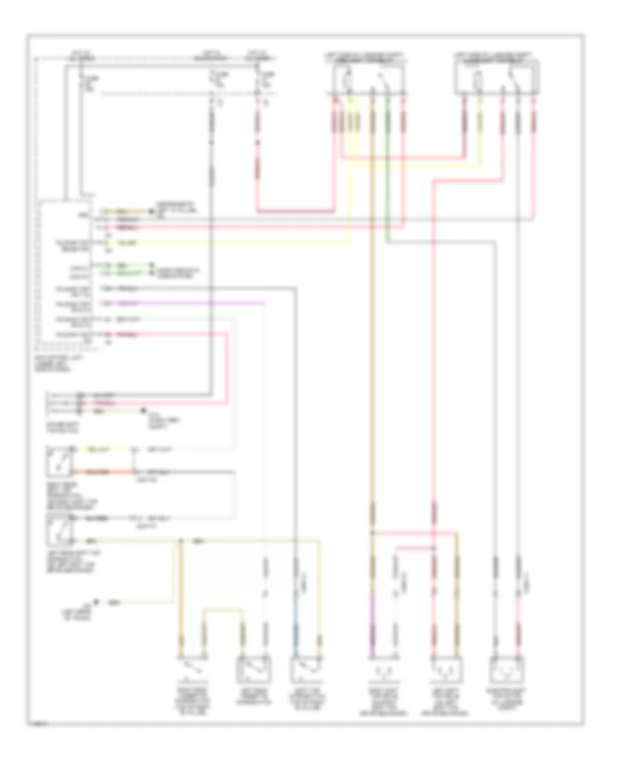
AIR CONDITIONING
1.0L
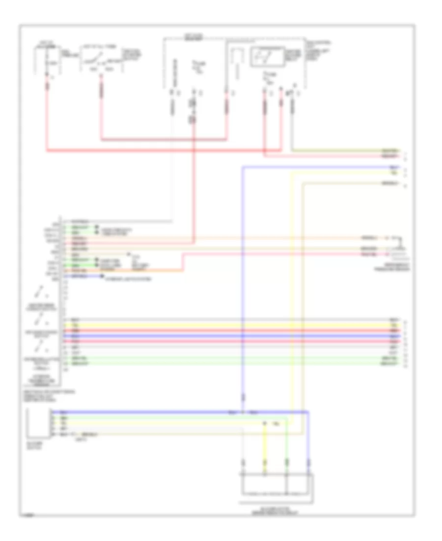
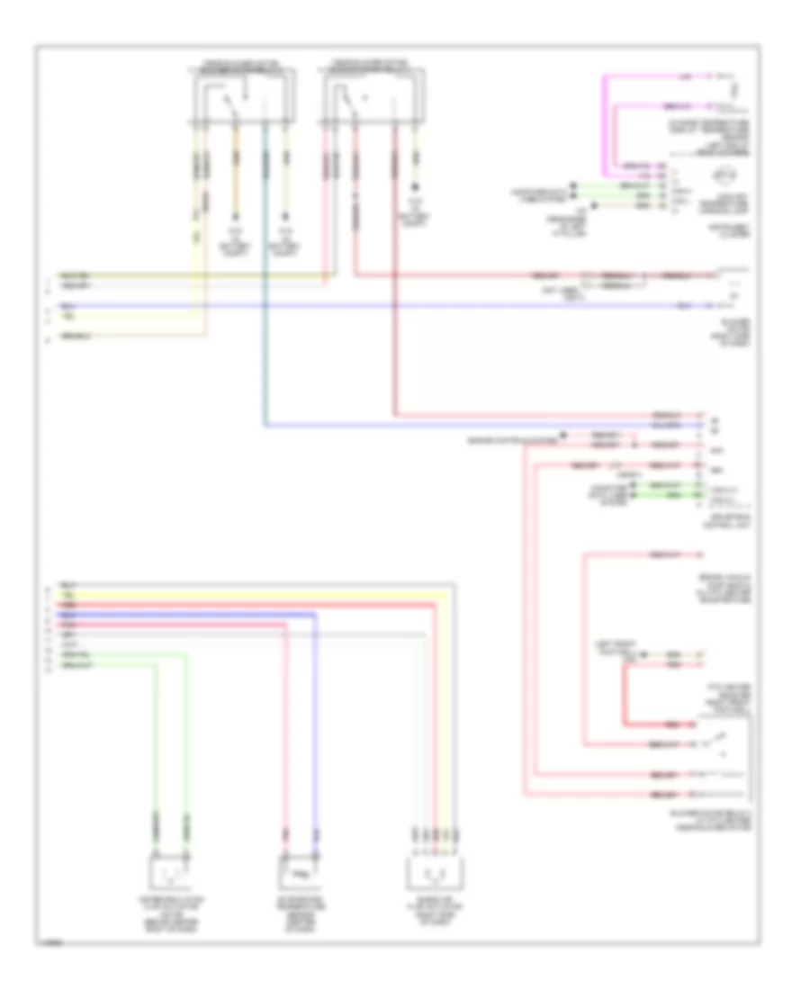
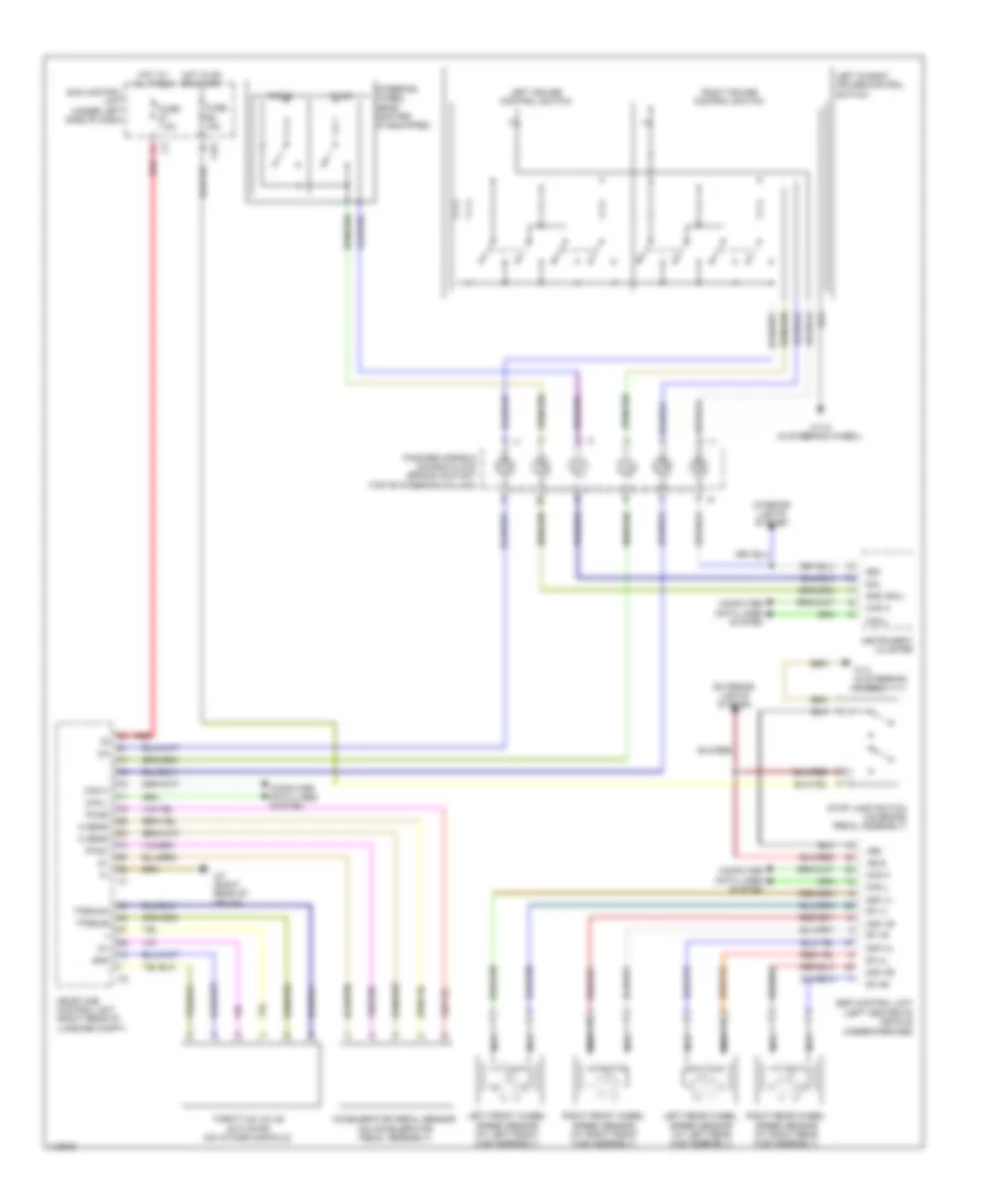
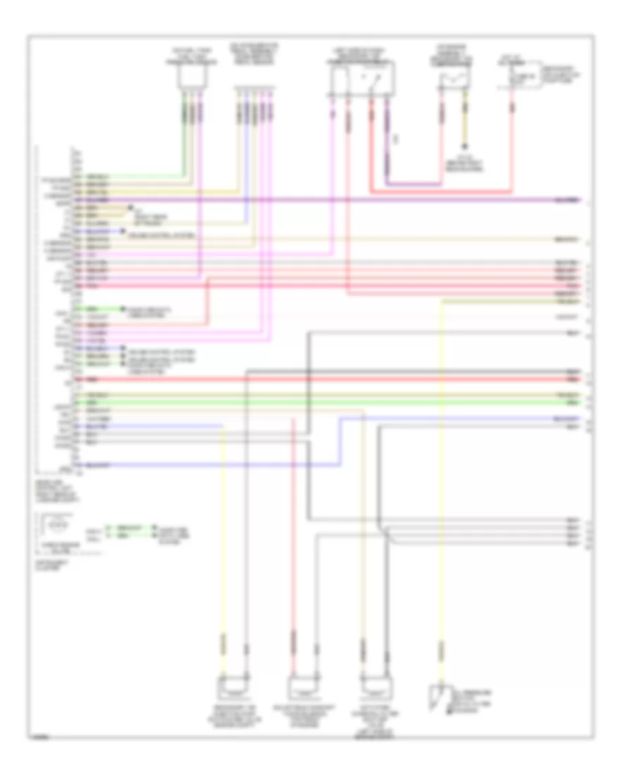
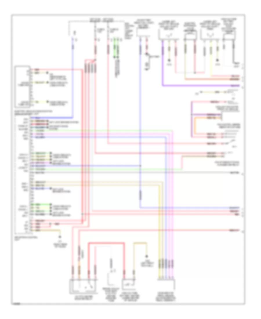
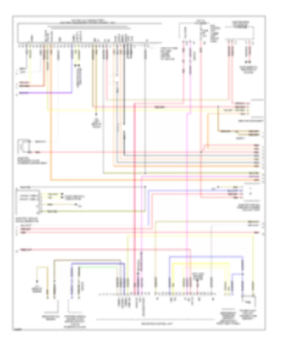
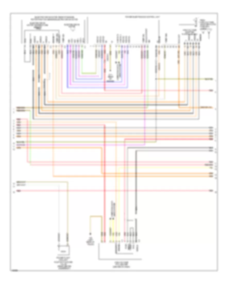
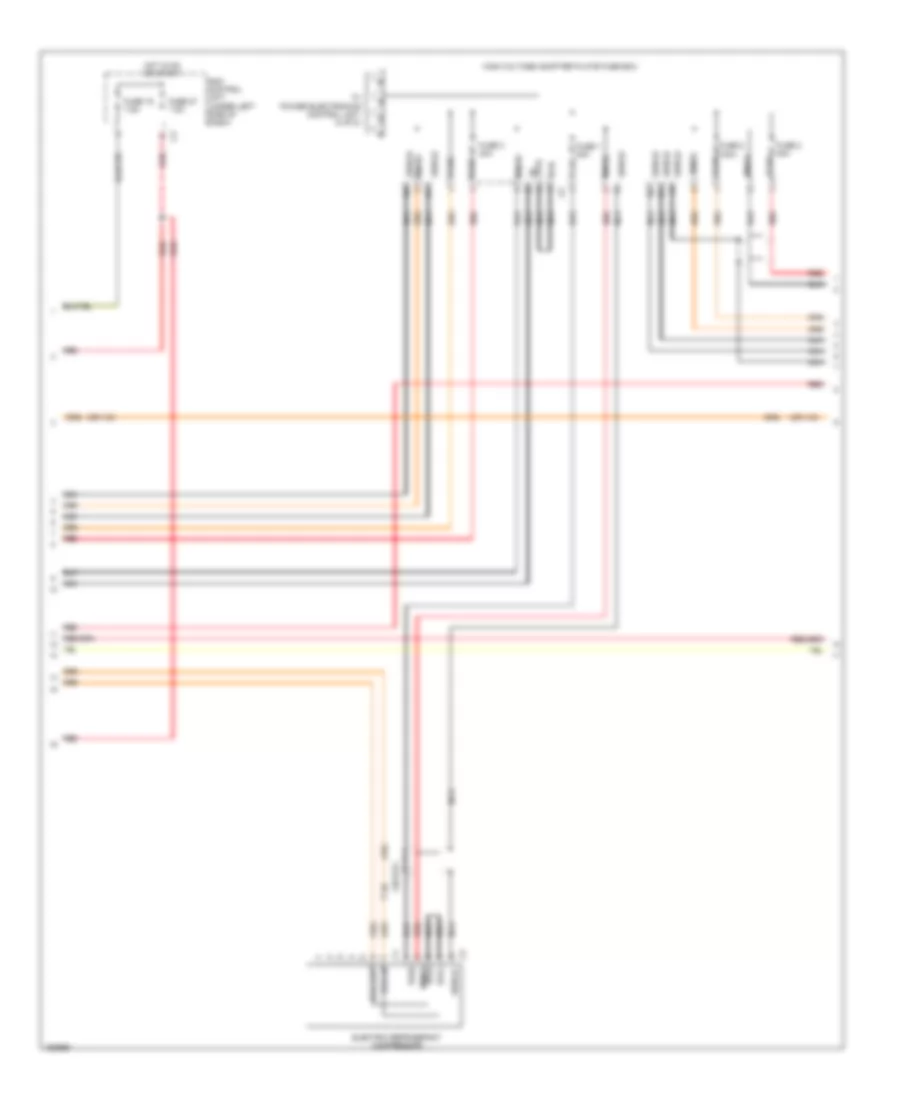
1.0L, Automatic A/C Wiring Diagram for Smart Fortwo Passion 2014
 https://portal-diagnostov.com/license.html
Automotive Electricians Portal FZCO
Automotive Electricians Portal FZCO
https://portal-diagnostov.com/license.html
https://portal-diagnostov.com/license.html
Automotive Electricians Portal FZCO
Automotive Electricians Portal FZCO
List of elements for 1.0L, Automatic A/C Wiring Diagram for Smart Fortwo Passion 2014:
- (+)
- (-)
- 100a
- 12v charge line prefuse (right front footwell along battery)
- 58d
- Acc
- Air conditioning switch
- Air recirculation flap actuator motor (behind center right of dash)
- Air recirculation switch
- Blend air flap actuator (right side of dash)
- Blower motor (right side of dash)
- Blower motor preresistor group (on blower motor)
- Blower switch
- C10
- Can e-h
- Can e-l
- Can h
- Can l
- Charge air fan motor & horn relay
- Charge air fan motor (on radiator assembly)
- Computer data lines system
- Coolant fan motor (front of vehicle)
- Coolant temperature sensor (rear of cylinder head)
- Coolant temperature warning lamp
- Dg +5v
- Dg sig
- Dgm
- Evaporator temperature sensor (center of dash)
- Fuse 10a
- Fuse 15a
- Fuse 25a
- Fuse 7.5a
- Heated rear window switch
- Heater blower relay
- Heating & air conditioning operating unit (center of dash)
- Hot at all times
- Hot in on or start
- Ignition starter switch
- Instrument cluster
- Interior lights system
- Interior temperature sensor
- Lock
- Me-sfi (me) control unit (right rear of luggage compt)
- Msens
- Outside temperature display temperature sensor (left end of front bumper)
- Pnk
- Red
- Refrigerant compressor (left front of engine)
- Refrigerant pressure sensor
- Run
- Rwh
- Sam control unit (under left side of dash)
- Start
- Tmot
- W10 (in battery compt)
- W26 (in battery compt)
- W43 (left side of service compt)
- W6 (left rear of trunk)
- W7 (right rear of trunk)
- W9 (near base of left "a" pillar)
- X26
- X85/10
ELECTRIC
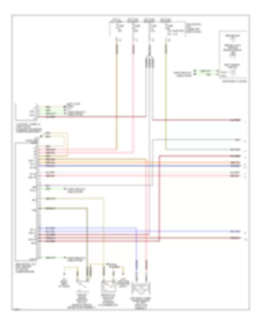
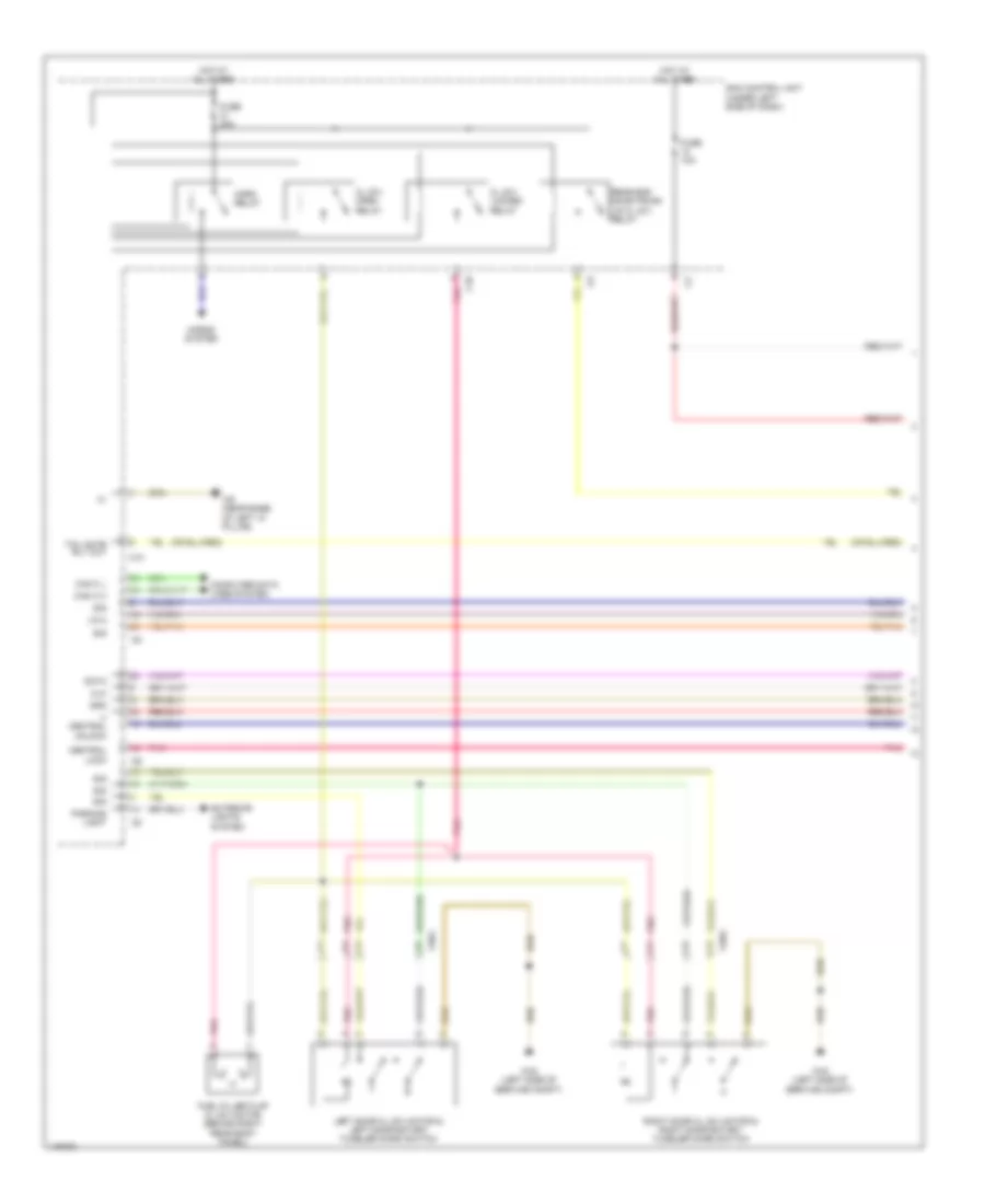
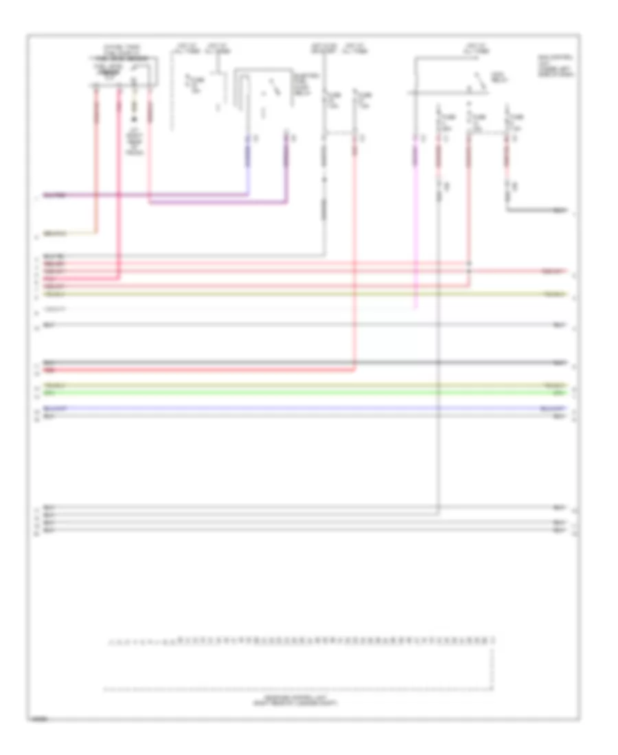
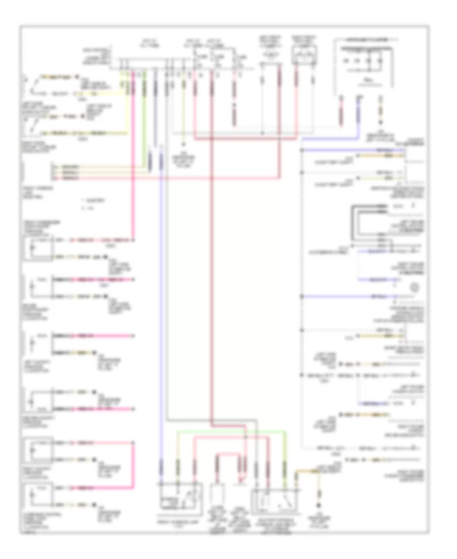
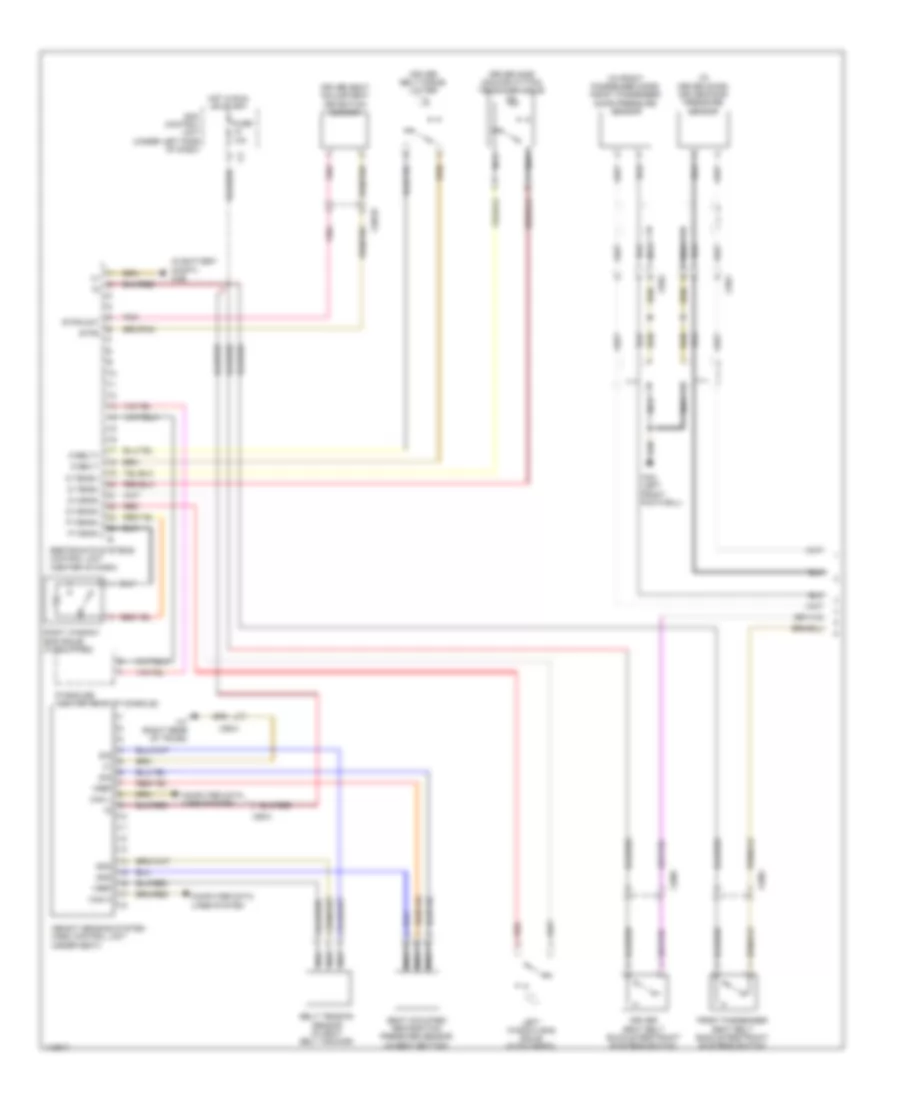
Electric, Automatic A/C Wiring Diagram (1 of 2) for Smart Fortwo Passion 2014
List of elements for Electric, Automatic A/C Wiring Diagram (1 of 2) for Smart Fortwo Passion 2014:
- 125a
- 58d
- Acc
- Air conditioning switch
- Air recirculation switch
- Blower motor series resistor group
- Blower switch
- Can c h
- Can c l
- Can h
- Can l
- Computer data lines system
- Dg +5v
- Dg sig
- Fuse 10a
- Fuse 25a
- Gnd
- Heated rear window switch
- Heater blower relay
- Heating & air conditioning operating unit (center of dash)
- Hot at all times
- Hot in on or start
- Ignition/ starter switch
- Interior lights system
- Interior temperature sensor
- Lock
- Pnk
- Red
- Refrigerant pressure sensor
- Run
- Rwh led sw in
- Sam control unit (under left side of dash)
- Sam prefuse
- Sig
- Start
- W10 (in battery compt)
- X85/10
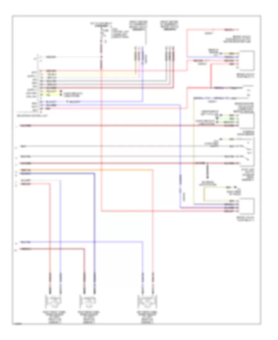
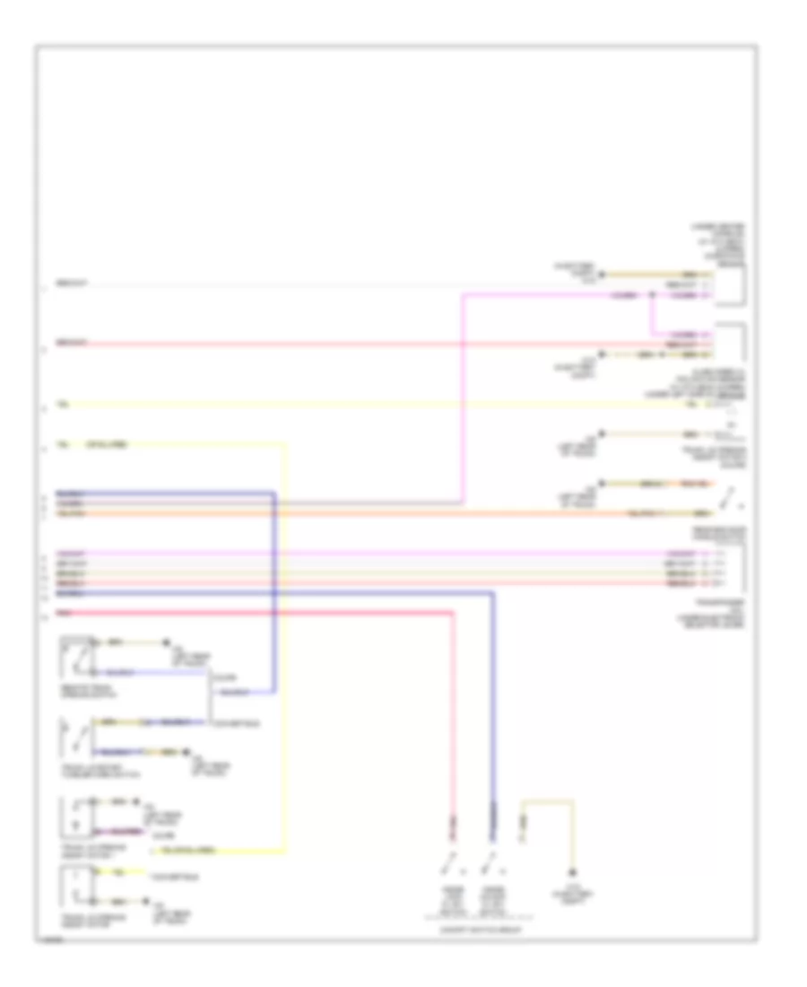
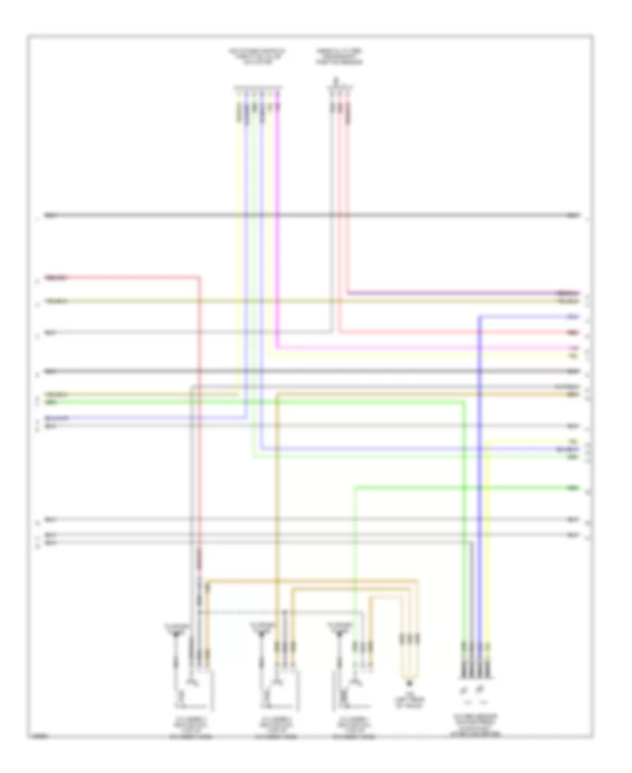
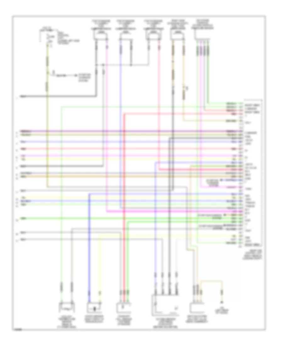
Electric, Automatic A/C Wiring Diagram (2 of 2) for Smart Fortwo Passion 2014
List of elements for Electric, Automatic A/C Wiring Diagram (2 of 2) for Smart Fortwo Passion 2014:
- (+)
- (-)
- (left front footwell) w83
- (near blower motor) blower motor relay 1
- (near blower motor) blower motor relay 2
- (not used)
- 64a
- 66a
- Air recirculation flap actuator motor (behind center right of dash)
- Blend air flap actuator (right side of dash)
- Blower motor (right side of dash)
- Blower motor relay 2 (w/ ptc heater) (near blower motor)
- Brake vacuum pump (bup) & 12v ptc heater booster fuse
- Can c h
- Can c l
- Can h
- Can l
- Computer data lines system
- Coolant temperature warning lamp
- Drivetrain control unit
- Engine controls system
- Evaporator temperature sensor (center of dash)
- Instrument cluster
- Outside temperature display temperature sensor (left end of front bumper)
- Pnk
- Ptc heater booster (right front footwell)
- Red
- W10 (in battery compt)
- W9 (near base of left "a" pillar)
- X26-ev1
- X85/10
ANTI-LOCK BRAKES
Anti-lock Brakes Wiring Diagram (1 of 2) for Smart Fortwo Passion 2014
List of elements for Anti-lock Brakes Wiring Diagram (1 of 2) for Smart Fortwo Passion 2014:
- (1.0l)
- (electric)
- (left floor panel) w14
- +bls
- +bs
- 15a
- Abs ind lamp
- Bfl
- Brake fluid & parking brake warning ind
- Brake fluid indicator switch (on brake fluid reservoir)
- Can h
- Can l
- Computer data
- Computer data lines system
- Df hl
- Df hr
- Df vl
- Df vr
- Esp control unit (left center of vehicle undercarriage)
- Esp warning lamp ind
- Fuse 10a
- Fuse 25a
- Fuse 40a
- Fuse r2 7.5a
- Has
- Hot at all times
- Hot in on or start
- Instrument cluster
- Left front wheel speed sensor (at left front hub assembly)
- Lines system
- Mdf hl
- Mdf hr
- Mdf vl
- Mdf vr
- Nca
- Parking brake indicator switch (base of parking brake lever assembly)
- Red/pnk
- Sam control unit (under left side of dash)
- Sound systems
- W10 (in battery compt)
- W43 (left side of service compt)
- W7 (right rear of trunk)
- Yaw rate, lateral & longitudinal acceleration sensor (under driver's seat)
Anti-lock Brakes Wiring Diagram (2 of 2) for Smart Fortwo Passion 2014
List of elements for Anti-lock Brakes Wiring Diagram (2 of 2) for Smart Fortwo Passion 2014:
- (front center of underbody) brake vacuum sensor 1
- (front center of underbody) brake vacuum sensor 2
- (near base of left "a" pillar) w9
- (rear of engine) w11
- Brake booster vacuum pump (under right rear of vehicle)
- Brake vacuum pump (bup) & 12v ptc heater booster fuse
- Brake vacuum pump relay (+)
- Brake vacuum pump relay (-)
- Can high
- Can low
- Computer data lines system
- Drivetrain control unit
- Evp
- Exterior lights system
- Fuse 7.5
- Gnd
- Hot w/ main relay energized
- Left rear wheel speed sensor (at left rear hub assembly)
- Nca
- Red
- Right front wheel speed sensor (at right front hub assembly)
- Right rear wheel speed sensor (at right rear hub assembly)
- Sam control unit (under left side of dash)
- Sig
- Steering angle sensor
- Stop lamp switch (on brake pedal assembly)
- W10 (in battery compt)
- W7 (right rear of trunk)
- X26-ev1
- X26-ev2
ANTI-THEFT
Anti-theft Wiring Diagram (1 of 2) for Smart Fortwo Passion 2014
List of elements for Anti-theft Wiring Diagram (1 of 2) for Smart Fortwo Passion 2014:
- C10
- Can c h
- Can c l
- Central
- Cl (zv) locked relay
- Cl (zv) open relay
- Clk
- Computer data lines system
- Data
- Exterior lights system
- Fuel filler flap cl (zv) motor (behind right rear body panel)
- Fuse 10a
- Fuse 20a
- Gnd
- Horn relay
- Horns system
- Hot at all times
- Left door cl (zv) motor & left door rotary tumbler micro switch
- Lin 2
- Lock
- Parking light
- Pnk
- Rear end door/trunk lid cl (zv) relay
- Right door cl (zv) motor & right door rotary tumbler micro switch
- Sam control unit (under left side of dash)
- Sig
- Tail gate rly out
- U central
- Unlock
- W43 (left side of service compt)
- W9 (near base of left "a" pillar)
- X35/1
- X35/2
Anti-theft Wiring Diagram (2 of 2) for Smart Fortwo Passion 2014
List of elements for Anti-theft Wiring Diagram (2 of 2) for Smart Fortwo Passion 2014:
- (in battery compt) w10
- (under center console) (w/ ata (edw) & siren) microwave sensor
- Alarm siren w/ inclination sensor (w/ ata (edw) & siren) (under left side of vehicle)
- Cockpit switch group
- Convertible
- Coupe
- Inside lock cl (zv) switch
- Inside unlock cl (zv) switch
- Pnk
- Rear end door handle switch
- Remote trunk opening switch
- Transponder coil (under electronic selector lever)
- Trunk lid opening assist motor
- Trunk lid opening assist motor 1
- Trunk lid opening assist motor 2 (coupe)
- Trunk lid rotary tumbler micro switch
- W10 (in battery compt)
- W6 (left rear of trunk)
BODY CONTROL MODULES
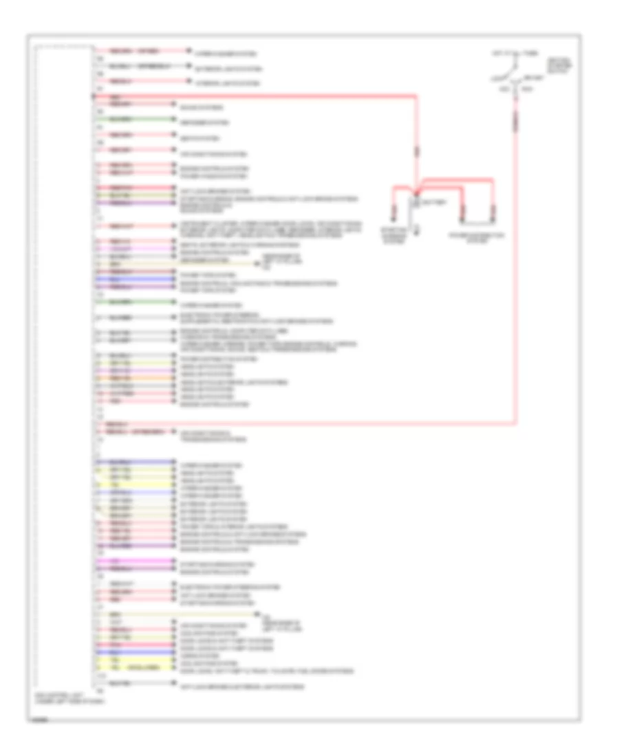
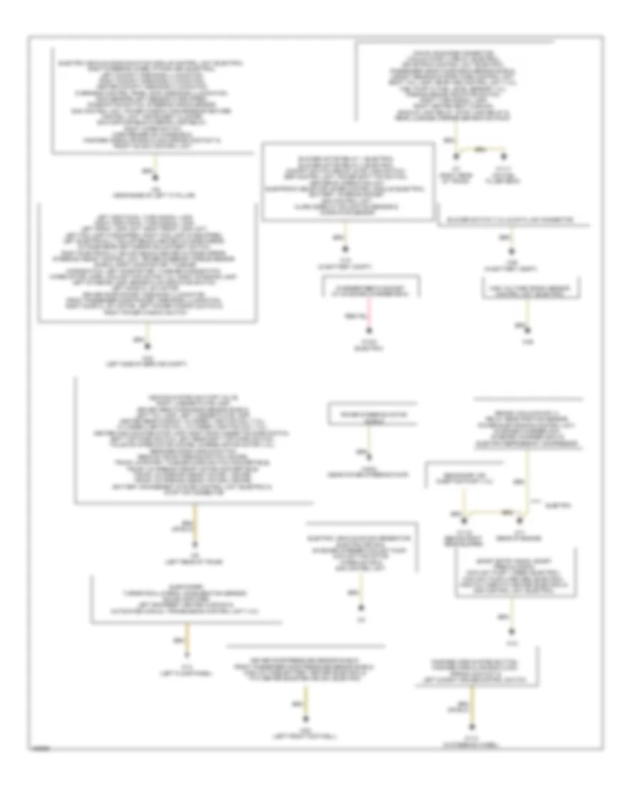
Body Control Modules Wiring Diagram (1 of 2) for Smart Fortwo Passion 2014
List of elements for Body Control Modules Wiring Diagram (1 of 2) for Smart Fortwo Passion 2014:
- (near base of left "a" pillar) w9
- (or red)
- Acc
- Air conditioning & transmissions systems
- Air conditioning system
- Anti-lock brakes & exterior lights systems
- Anti-lock brakes system
- Battery
- C10
- Cooling fans system
- Defogger system
- Door locks & anti-theft systems
- Door locks, anti-theft & trunk, tailgate, fuel doors systems
- Electronic power steering system
- Engine controls & anti-lock brakes systems
- Engine controls & transmissions systems
- Engine controls system
- Engine controls, computer data lines, warning & transmissions systems
- Engine controls, cooling fans & transmissions systems
- Exterior lights system
- Headlights & exterior lights systems
- Headlights system
- Horns system
- Hot at all times
- Ignition/ starter switch
- Instrument cluster, wiper/washer, door locks, air conditioning, exterior lights, computer data lines, defogger, interior lights, warning, anti-theft, headlights & transmissions systems
- Interior lights system
- Lock
- Pnk
- Power distribution system
- Power tops & interior lights systems
- Power tops system
- Power windows system
- Red
- Red/pnk
- Run
- Sam control unit (under left side of dash)
- Seats system
- Seats, exterior lights & warning systems
- Sound systems
- Start
- Starting/ charging system
- Starting/charging system
- Starting/charging, engine controls & anti-lock brake systems engine controls & sound systems
- W9 (near base of left "a" pillar)
- Wiper/washer system
- Wiper/washer, mirrors, power tops, engine controls, warning, air conditioning, sound, seats & transmissions systems
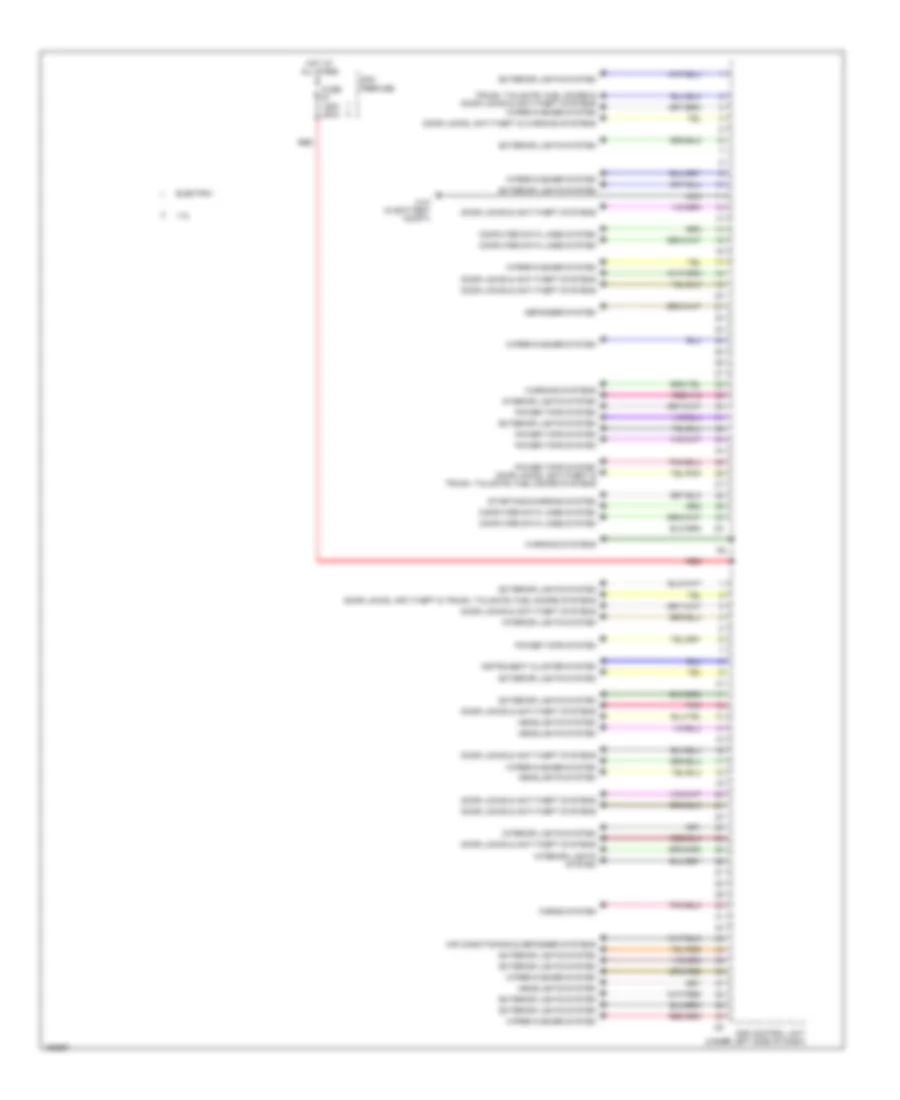
Body Control Modules Wiring Diagram (2 of 2) for Smart Fortwo Passion 2014
List of elements for Body Control Modules Wiring Diagram (2 of 2) for Smart Fortwo Passion 2014:
- 1.0l
- Air conditioning & defogger systems
- Computer data lines system
- Defogger system
- Door locks & anti-theft systems
- Door locks, anti-theft & trunk, tailgate, fuel doors systems
- Door locks, anti-theft & warning systems
- Electric
- Exterior lights system
- Fuse 125a 200a
- Headlights system
- Horns system
- Hot at all times
- Instrument cluster system
- Interior lights system
- Nca
- Pnk
- Power tops system
- Power tops system door locks, anti-theft & trunk, tailgate, fuel doors systems
- Red
- Sam control unit (under left side of dash)
- Sam prefuse
- Starting/charging system
- Trunk, tailgate, fuel doors & door locks & anti-theft systems wiper/washer system
- W10 (in battery compt)
- Warning systems
- Wiper/washer system
COMPUTER DATA LINES
1.0L
1.0L, Computer Data Lines Wiring Diagram for Smart Fortwo Passion 2014
List of elements for 1.0L, Computer Data Lines Wiring Diagram for Smart Fortwo Passion 2014:
- (in battery compt) w26
- Automated manual transmission control unit (under driver's seat)
- Can c h
- Can c l
- Can h
- Can l
- Card reader on windshield (if equipped)
- Data link connector (left side of dash)
- Electronic selector lever module control module (under center console)
- Esp control unit (left center of vehicle undercarriage)
- Fuse 10a
- Fuse 7.5a
- Heating & air conditioning operating unit (if equipped) (center of dash)
- Hot at all times
- Hot in on or start
- Instrument cluster
- Me-sfi (me) control unit (right rear of luggage compt)
- Restraints systems control unit (center of dash)
- Sam control unit (under left side of dash)
- Steering angle sensor
- Steering assist control unit (w/ power steering) (behind instrument cluster)
- Tpm (rdk) control unit (left side of dash)
- Turn rate & lateral acceleration sensor
- W/ power steering
- Weight sensing system (wss) control unit (under seat)
- X55/4
ELECTRIC
Electric, Computer Data Lines Wiring Diagram (1 of 2) for Smart Fortwo Passion 2014
List of elements for Electric, Computer Data Lines Wiring Diagram (1 of 2) for Smart Fortwo Passion 2014:
- (in battery compt) w26
- Battery management system control unit (on high voltage battery)
- C13
- Can c h
- Can c l
- Can ev bus node connector
- Can ev tube hi
- Can ev tube lo
- Can h
- Can l
- Data link connector (left side of dash)
- Drivetrain control unit
- Electric vehicle communication module control unit
- Electric vehicle sound generator
- Fuse 10a
- Fuse 7.5a
- High-voltage crash sensor control unit
- High-voltage ptc heater (center of dash)
- Hot at all times
- Hot in on or start
- Me-sfi (me) control unit (right rear of luggage compt)
- Onboard charger 22kw
- Onboard charger 3kw
- Power electronics control unit
- Sam control unit (under left side of dash)
- W7 (right rear of trunk)
Electric, Computer Data Lines Wiring Diagram (2 of 2) for Smart Fortwo Passion 2014
List of elements for Electric, Computer Data Lines Wiring Diagram (2 of 2) for Smart Fortwo Passion 2014:
- Automated manual transmission control unit (under driver's seat)
- Can c h
- Can c l
- Can h
- Can l
- Card reader on windshield (if equipped)
- Electronic selector lever module control unit (under center console)
- Esp control unit (left center of vehicle undercarriage)
- Heating & a/c operating unit (center of dash)
- Instrument cluster
- Restraints systems control unit (center of dash)
- Sensor
- Steering angle sensor
- Steering assist control unit (w/ power steering) (behind instrument cluster)
- Tpm (rdk) control unit (left side of dash)
- Turn rate & lateral acceleration
- W/ power steering
- Weight sensing system (wss) control unit (under seat)
- X55/4
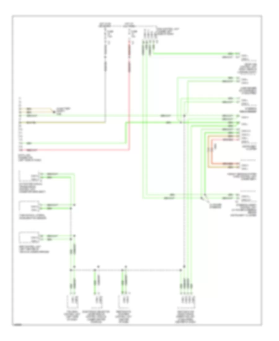
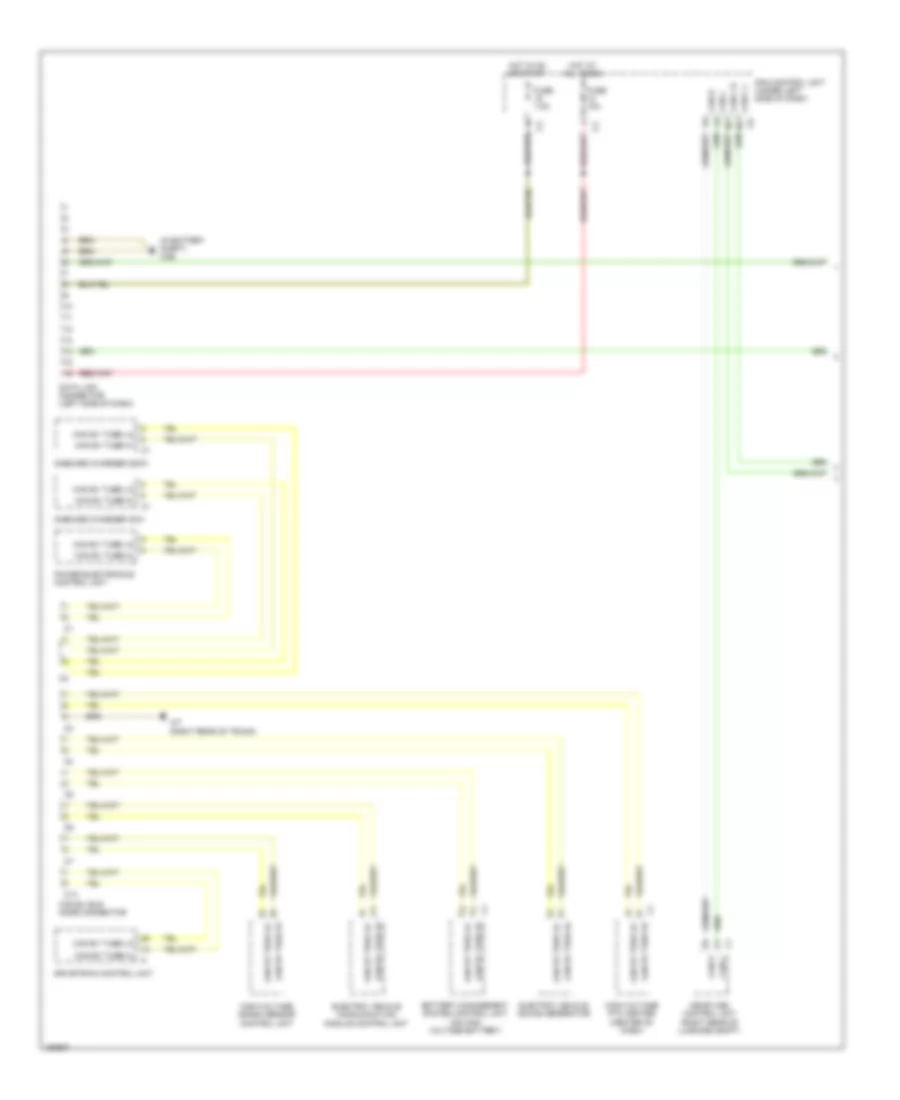
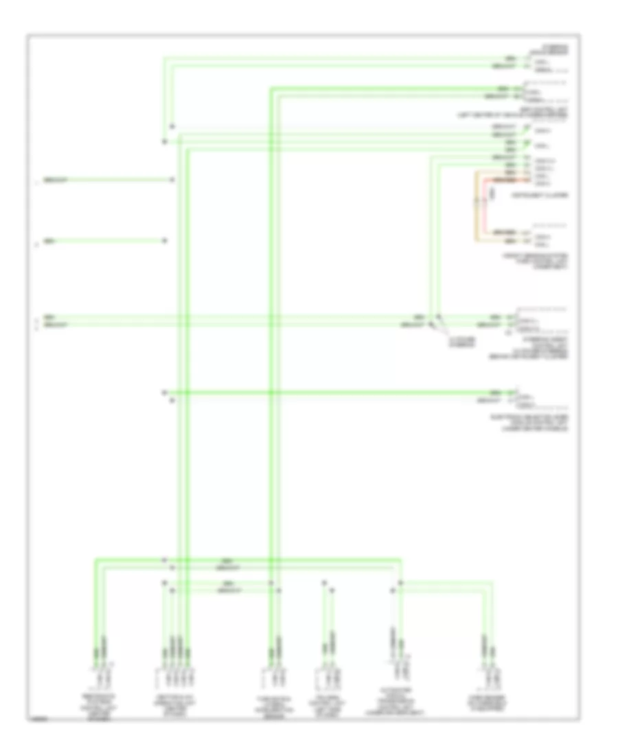
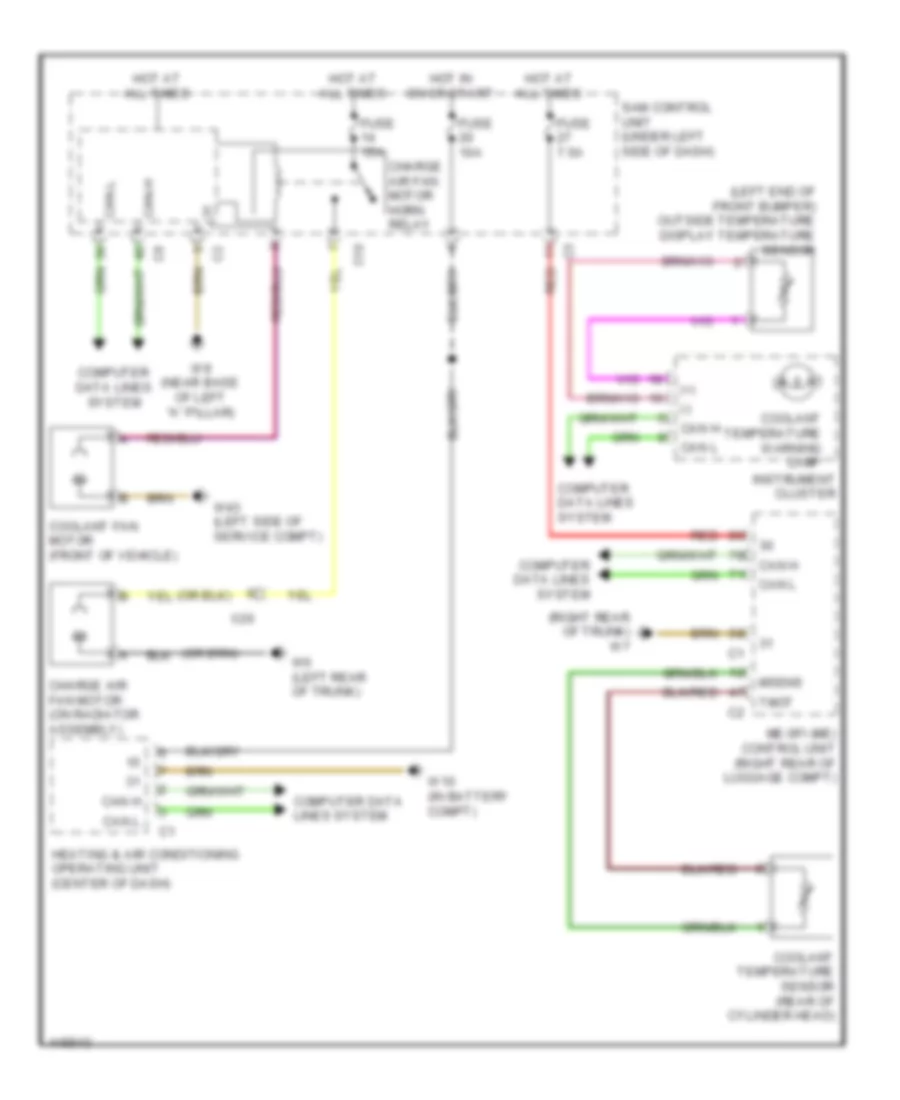
COOLING FAN
Cooling Fan Wiring Diagram for Smart Fortwo Passion 2014
List of elements for Cooling Fan Wiring Diagram for Smart Fortwo Passion 2014:
- (+)
- (-)
- (left end of front bumper) outside temperature display temperature sensor
- (right rear of trunk) w7
- C10
- Can h
- Can l
- Can-h
- Can-l
- Charge air fan motor (on radiator assembly)
- Charge air fan motor horn relay
- Computer data lines system
- Coolant fan motor (front of vehicle)
- Coolant temperature sensor (rear of cylinder head)
- Coolant temperature warning lamp
- Fuse 10a
- Fuse 15a
- Fuse 7.5a
- Heating & air conditioning operating unit (center of dash)
- Hot at all times
- Hot in on or start
- Instrument cluster
- Me-sfi (me) control unit (right rear of luggage compt)
- Msens
- Red
- Sam control unit (under left side of dash)
- Tmot
- W10 (in battery compt)
- W43 (left side of service compt)
- W6 (left rear of trunk)
- W9 (near base of left "a" pillar)
- X26
CRUISE CONTROL
Cruise Control Wiring Diagram for Smart Fortwo Passion 2014
List of elements for Cruise Control Wiring Diagram for Smart Fortwo Passion 2014:
- (left center of vehicle undercarriage)
- +bls
- +bs
- 58d
- Accelerator pedal sensor (on accelerator pedal assembly)
- Can h
- Can l
- Computer data lines system
- Cr2
- Df hl
- Df hr
- Df vl
- Df vr
- Esp control unit
- Exterior lights system
- Fanfare horns & air bag clock spring contact (top of steering column)
- Fuse 7.5a
- Fuse r2 15a
- Gnd
- Gnd (sal)
- Hot at all times
- Hot in on or start
- Instrument cluster
- Interior lights system
- Left & right cruise control switch
- Left cruise control switch
- Left front wheel speed sensor (at left front hub assembly)
- Left rear wheel speed sensor (at left rear hub assembly)
- M sens
- Mdf hl
- Mdf hr
- Mdf vl
- Mdf vr
- Me-sfi (me) control unit (right rear of luggage compt)
- Minus
- Nca
- Plus
- Pwg1
- Pwg2
- Red
- Right cruise control switch
- Right front wheel speed sensor (at right front hub assembly)
- Right rear wheel speed sensor (at right rear hub assembly)
- Sal
- Sam control unit (under left side of dash)
- Steering wheel gear shifter (if equipped)
- Stop lamp switch (on brake pedal assembly)
- Throttle valve actuator (on intake manifold)
- Tpsmain
- Tpssub
- W10 (in steering wheel)
- W110 (in steering wheel)
- W7 (right rear of trunk)
DEFOGGERS
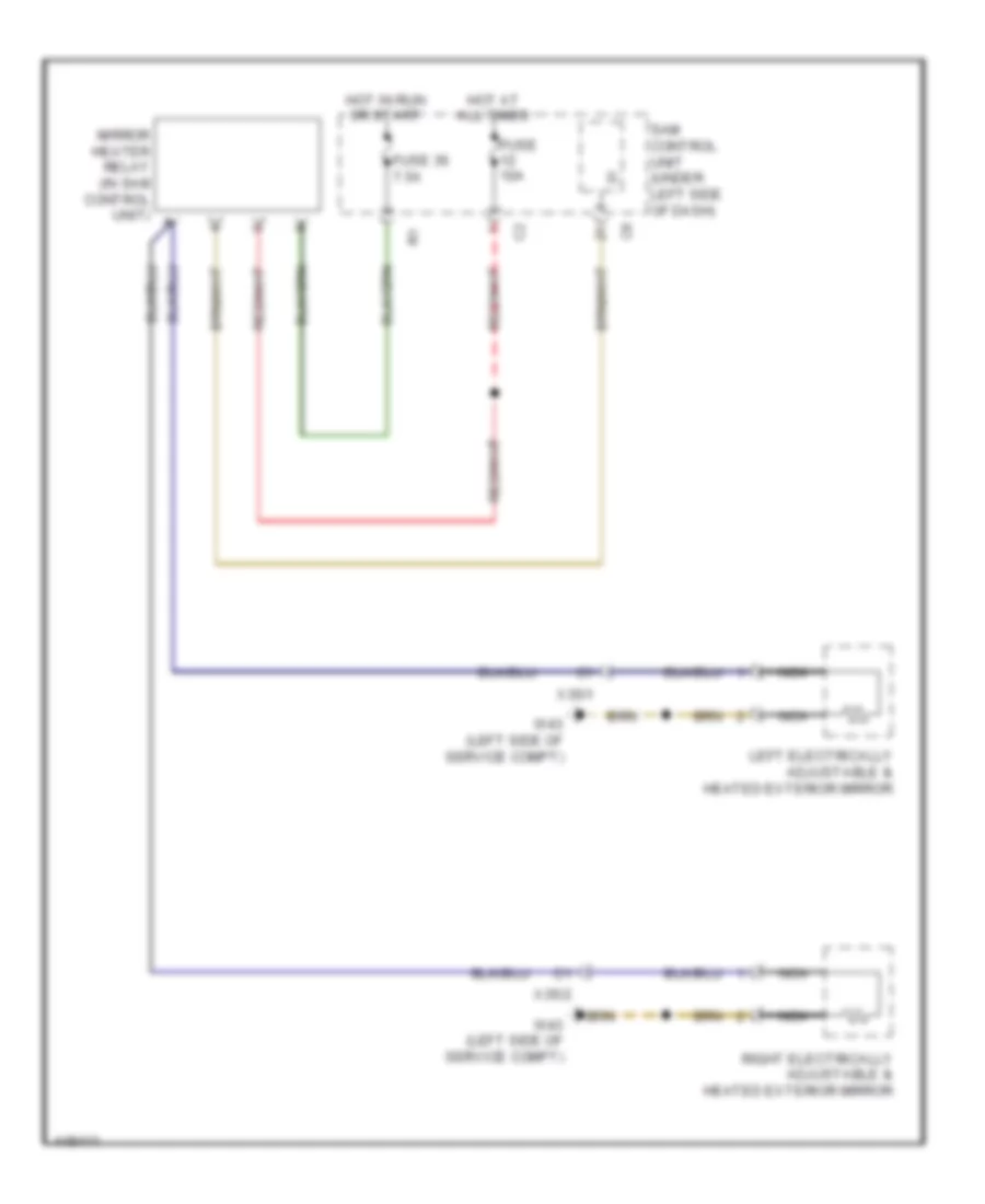
Heated Mirrors Wiring Diagram for Smart Fortwo Passion 2014
List of elements for Heated Mirrors Wiring Diagram for Smart Fortwo Passion 2014:
- Fuse 10a
- Fuse 36 7.5a
- Hot at all times
- Hot in run or start
- Left electrically adjustable & heated exterior mirror
- Mirror heater relay (in sam control unit)
- Nca
- Right electrically adjustable & heated exterior mirror
- Sam control unit (under left side of dash)
- W43 (left side of service compt)
- X35/1
- X35/2
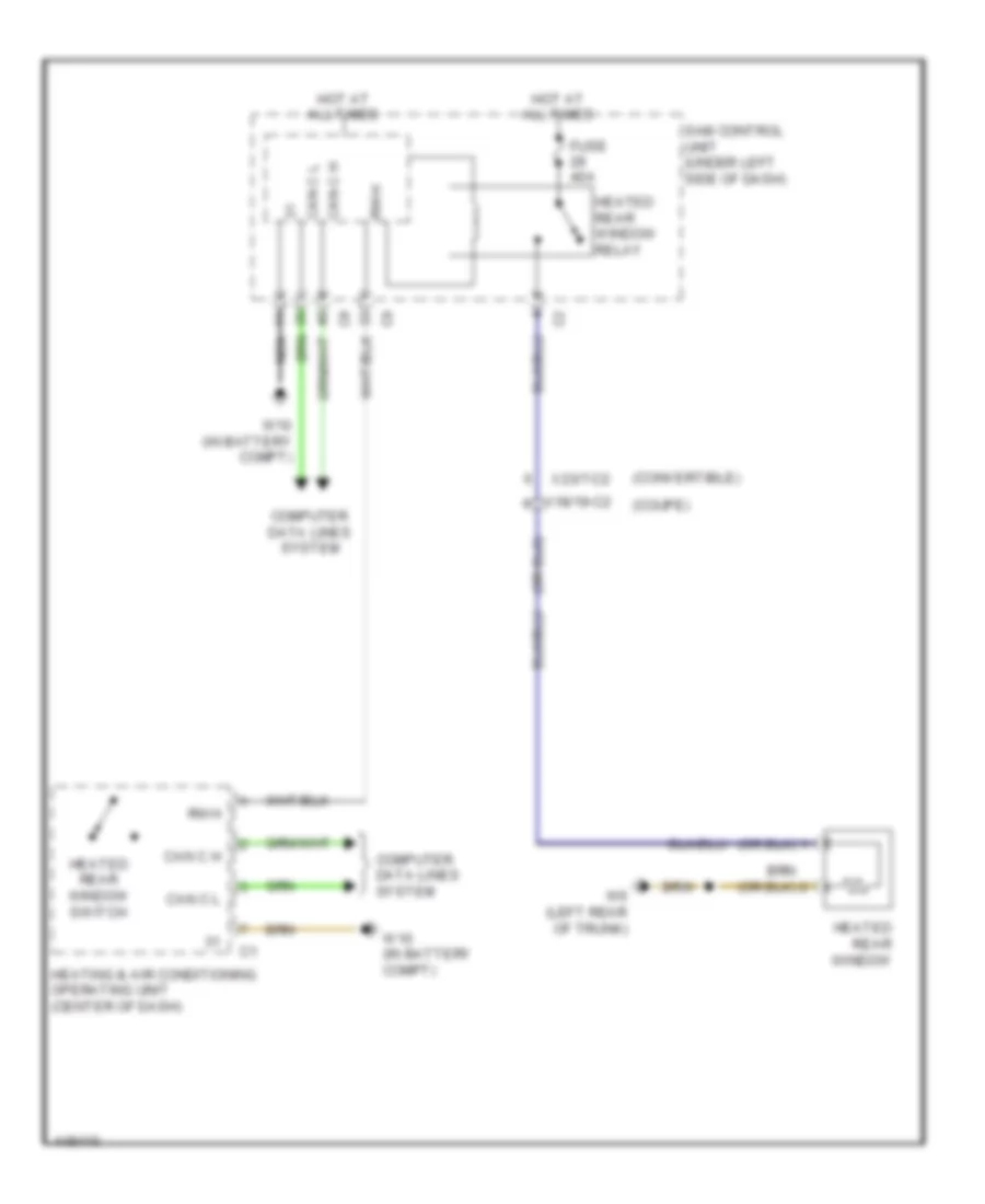
Rear Defogger Wiring Diagram for Smart Fortwo Passion 2014
List of elements for Rear Defogger Wiring Diagram for Smart Fortwo Passion 2014:
- (convertible)
- (coupe)
- Can c h
- Can c l
- Computer data lines system
- Fuse 40a
- Heated rear window
- Heated rear window relay
- Heated rear window switch
- Heating & air conditioning operating unit (center of dash)
- Hot at all times
- Nca
- Rwh
- Sam control unit (under left side of dash)
- W10 (in battery compt)
- W6 (left rear of trunk)
- X18/19-c2
- X23/7-c2
ELECTRONIC POWER STEERING
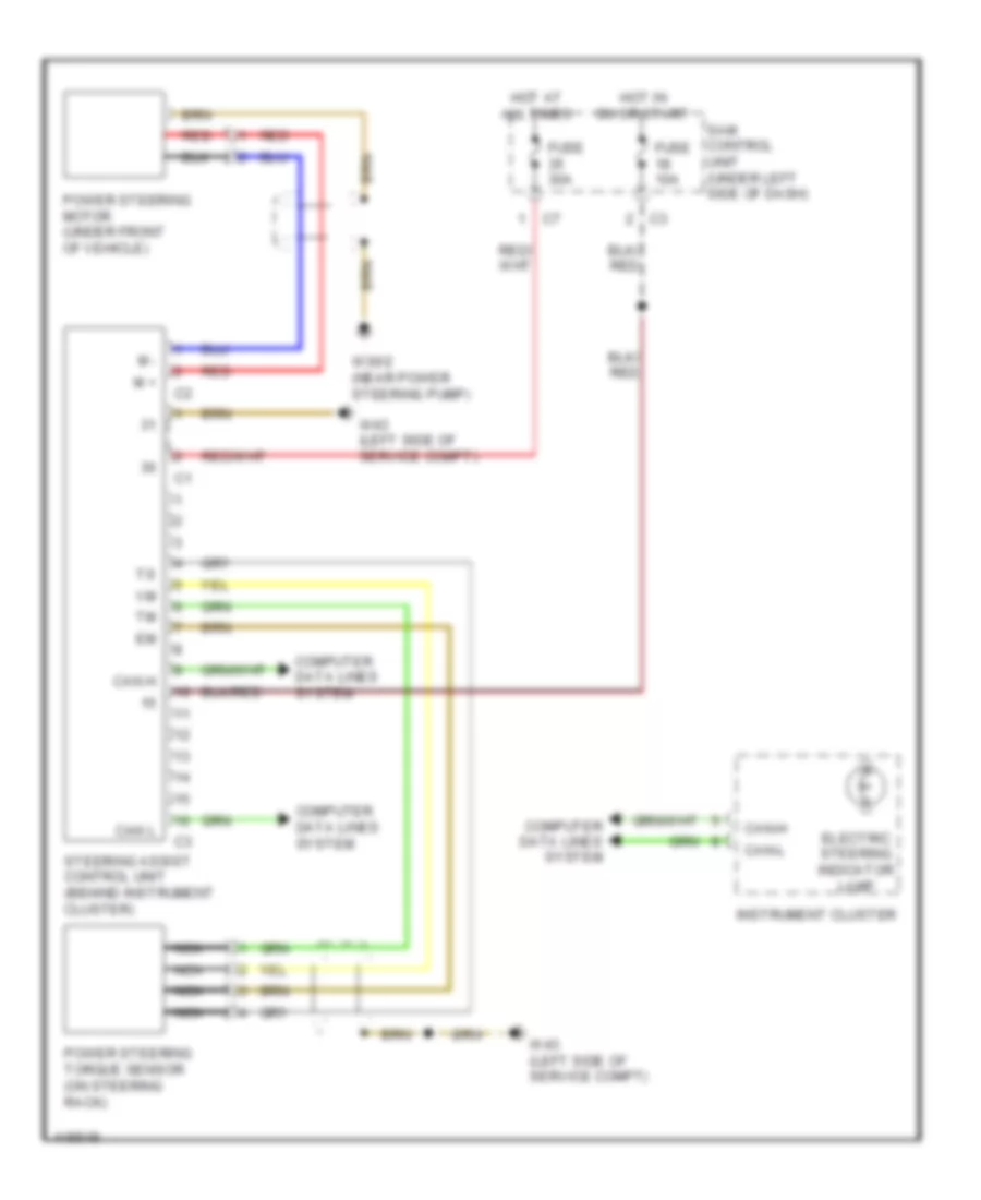
Electronic Power Steering Wiring Diagram for Smart Fortwo Passion 2014
List of elements for Electronic Power Steering Wiring Diagram for Smart Fortwo Passion 2014:
- Can h
- Can l
- Can-h
- Can-l
- Computer data lines system
- Electric steering indicator lamp
- Fuse 10a
- Fuse 30a
- Hot at all times
- Hot in on or start
- Instrument cluster
- M +
- M -
- Nca
- Power steering motor (under front of vehicle)
- Power steering torque sensor (on steering rack)
- Red
- Sam control unit (under left side of dash)
- Steering assist control unit (behind instrument cluster)
- W30/2 (near power steering pump)
- W43 (left side of service compt)
ENGINE PERFORMANCE
1.0L
1.0L, Engine Performance Wiring Diagram (1 of 4) for Smart Fortwo Passion 2014
List of elements for 1.0L, Engine Performance Wiring Diagram (1 of 4) for Smart Fortwo Passion 2014:
- (left side of dash) secondary air injection pump relay
- (on accelerator pedal assembly) accelerator pedal sensor
- (on engine assembly) secondary air injection pump
- (on fuel tank) fuel tank pressure sensor
- 87/1.1
- Activated charcoal filter shut-off valve (left side of engine compt)
- Adjustable camshaft timing solenoid (top front of engine)
- Air pump
- Can h
- Can l
- Check engine mil ind
- Computer data lines system
- Cruise control system
- Cruise control system computer data lines system
- Ekpr
- Euv
- Fuse 36 50a
- Gnd
- Hot at all times
- Instrument cluster
- Kwdg
- Lshhk
- M sensor
- Me-sfi (me) control unit (right rear of luggage compt)
- Nwdg
- Nws
- Oil pressure switch (on oil filter housing)
- Pnk
- Pwg1
- Pwg2
- Red
- Secondary air injection pump fuse
- Secondary air injection pump switchover valve (engine compt)
- Sig
- Tev
- Tp gnd
- Tp sig
- Tp source
- W11/5 (behind right rear bumper)
- W7 (right rear of trunk)
- X15
1.0L, Engine Performance Wiring Diagram (2 of 4) for Smart Fortwo Passion 2014
List of elements for 1.0L, Engine Performance Wiring Diagram (2 of 4) for Smart Fortwo Passion 2014:
- (in fuel tank) fuel pump w/ fuel level sensor
- Electric fuel pump relay
- Fuel level sensor
- Fuse 15a
- Fuse 25a
- Fuse 7.5a
- Hot at all times
- Hot in on or start
- Main relay
- Me-sfi(me) control unit (right rear of luggage compt)
- Pnk
- Red
- Sam control unit (under left side of dash)
- W7 (right rear of trunk)
- X26
1.0L, Engine Performance Wiring Diagram (3 of 4) for Smart Fortwo Passion 2014
List of elements for 1.0L, Engine Performance Wiring Diagram (3 of 4) for Smart Fortwo Passion 2014:
- (near oil filter) crankshaft position sensor
- (on intake manifold) throttle valve actuator
- Cylinder 1 ignition coil (top of cylinder head)
- Cylinder 2 ignition coil (top of cylinder head)
- Cylinder 3 ignition coil (top of cylinder head)
- Nca
- Oxygen sensor (downstream) (in exhaust, after converter)
- Red
- Sig
- To spark plugs
- W6 (left rear of trunk)
- X26
1.0L, Engine Performance Wiring Diagram (4 of 4) for Smart Fortwo Passion 2014
List of elements for 1.0L, Engine Performance Wiring Diagram (4 of 4) for Smart Fortwo Passion 2014:
- (+)
- (-)
- (on intake manifold) intake manifold pressure sensor
- (right side of engine compt) fuel tank vent valve
- (top of engine) cylinder 1 fuel injection valve
- (top of engine) cylinder 2 fuel injection valve
- (top of engine) cylinder 3 fuel injection valve
- Boost sens
- Camshaft hall sensor (top rear of engine)
- Charging
- Coolant temperature sensor (rear of cylinder head)
- Ev1
- Ev2
- Ev3
- Fuse 25a
- Heating system shutoff valve (rear underbody)
- Hm valve
- Hot at all times
- Knock sensor (right front of engine block)
- Ksa
- Ksb
- Lshk
- Lshm
- Lshvk
- Lsuvm
- Lsvk
- M sensor
- Me-sfi (me) control unit (right rear of luggage compt)
- Nca
- Oalv
- Oxygen sensor (upstream) (in exhaust, before converter)
- Pnk
- Poel
- Red
- Sam control unit (under left side of dash)
- Sig
- Starting/
- Starting/ charging system
- Starting/charging system
- System
- Tans
- Tmot
- Tpsmain
- Tpssub
- W6 (left rear of trunk)
- X26
- Zeu3
- Zue1
- Zue2
ELECTRIC
Electric, Engine Performance Wiring Diagram (1 of 5) for Smart Fortwo Passion 2014
List of elements for Electric, Engine Performance Wiring Diagram (1 of 5) for Smart Fortwo Passion 2014:
- (right rear of trunk)
- (under center of vehicle)
- (under left front of vehicle) coolant pump 1 (feed)
- (under left front of vehicle) coolant pump 2 (return)
- 12v ptc heater booster relay
- 30g
- 30z
- Accelerator pedal sensor (on accelerator pedal assembly)
- Air conditioning system
- Anti-lock
- Anti-lock brakes system
- Aps
- Battery
- Battery sensor
- Blower
- Brake vacuum pump (bvp) & 12v ptc heater booster fuse
- Brakes system
- Can c h
- Can c l
- Can ev h
- Can ev l
- Can ev tube high
- Can ev tube low
- Computer data lines system
- Coolant fan motor (front of vehicle)
- Drivetrain control unit
- Electric expansion valve (battery)
- Electric vehicle communication module control unit
- Evp
- Fan
- Fan control series resistor (2-stage)
- Fan stage switching changeover relay
- Fuse 30 40a
- Fuse 9 7.5a
- Gnd
- Gnd 1
- Gnd 2
- High-voltage battery coolant pump switchover valve
- High-voltage battery heater
- Hot in on or start
- Lin batt
- Red
- Red/pnk
- Sam control unit (under left side of dash)
- Sig
- Sig 2
- Sply
- W12
- W83 (left front footwell)
- W9 (near base of left "a" pillar)
- Wake up
- X26-ev1
Electric, Engine Performance Wiring Diagram (2 of 5) for Smart Fortwo Passion 2014
List of elements for Electric, Engine Performance Wiring Diagram (2 of 5) for Smart Fortwo Passion 2014:
- (center rear of console) pyrofuse
- (on high voltage battery) battery management system control unit
- 30c
- 87c
- Anti-lock brakes system
- Brakes system anti-lock
- C10
- Can ev h
- Can ev l
- Can ev tube hi
- Can ev tube lo
- Cdl open
- Computer data lines system
- Drivetrain control unit
- Electric drive & onboard charger coolant pump
- Electric expansion valve (interior compartment)
- Electric vehicle sound generator
- Evp
- Fanfare horns & air bag clock spring contact (top of steering column)
- Fuse r5 10a
- Gear position sensor
- Gearbox
- Gnd
- High-voltage battery (under center of vehicle)
- Hot at all times
- Hvil
- Hvil in a/c valve
- Hvil out
- Hvil shield
- Minus
- Nca
- Opl ls
- Plus
- Pnk
- Power plant coolant temperature sensor 1
- Pwm 1
- Pwm 2
- Red
- Refrigerant pressure sensor 2 (behind right front body panel)
- Release start
- Sam control unit (under left side of dash)
- Service disconnect
- Shield
- Sig
- Temp sig
- Tempm 1
- Tempm 2
- W11 (rear of engine)
- W6 (left rear of trunk)
- Wake up
- X26-ev1
- X26-ev2
Electric, Engine Performance Wiring Diagram (3 of 5) for Smart Fortwo Passion 2014
List of elements for Electric, Engine Performance Wiring Diagram (3 of 5) for Smart Fortwo Passion 2014:
- (electric drive motor: rear of engine)
- 30c
- Can ev h
- Can ev l
- Computer data lines system
- Cos +
- Cos -
- Electric drive motor
- Electric drive motor temperature sensor
- From high-voltage adapter plate fuse box (4 of 5)
- High-voltage adapter plate fuse box
- High-voltage ptc heater (center of dash)
- Hvil
- Hvil in
- Hvil out
- Lines system computer data
- Minus hvil
- Nca
- Plus
- Power electronics control unit
- Power plant coolant pump switchover valve (rear center underbody)
- Red
- Ref
- Relace start
- Res r1
- Res r2
- Res s1
- Res s2
- Res s3
- Res s4
- Rotor position sensor/electric drive motor
- Shield
- Sin +
- Sin -
- Sply
- Temp gnd
- Temp sig
- W11 (rear of engine)
- W6 (left rear of trunk)
- X26-ev1
- X26-ev2
Electric, Engine Performance Wiring Diagram (4 of 5) for Smart Fortwo Passion 2014
List of elements for Electric, Engine Performance Wiring Diagram (4 of 5) for Smart Fortwo Passion 2014:
- Electric refrigerant compressor
- Fuse 1 40a
- Fuse 19 7.5a
- Fuse 2 100a
- Fuse 2 40a
- Fuse 27 7.5a
- Fuse 3 40a
- High-voltage adapter plate fuse box
- Hot in on or start
- Hvil
- Hvil in
- Hvil out
- Hvil sc
- Minus
- Minus hvil
- Minus shield
- Nca
- Plus
- Red
- Sam control unit (under left side of dash)
- Shield
- T0 power electronics control unit (3 of 5)
- X26-ev2
Electric, Engine Performance Wiring Diagram (5 of 5) for Smart Fortwo Passion 2014
List of elements for Electric, Engine Performance Wiring Diagram (5 of 5) for Smart Fortwo Passion 2014:
- (or red)
- 1hv
- 22kw onboard charger
- 2hv
- 30c
- 3kw onboard charger
- 3kw/22kw onboard charger
- Can ev h
- Can ev l
- Charge socket flap cl (zv) motor
- Charger feed-in socket
- Computer data lines system
- Gnd
- Hvil
- Hvil at
- Hvil in
- Lck motor +
- Lck motor -
- Lck sw
- Led gn
- Led red
- Led white
- Minus
- Nca
- Plus
- Red
- Shield
- Temp sig
- W11 (rear of engine)
- W15/3
- X26-ev2
EXTERIOR LIGHTS
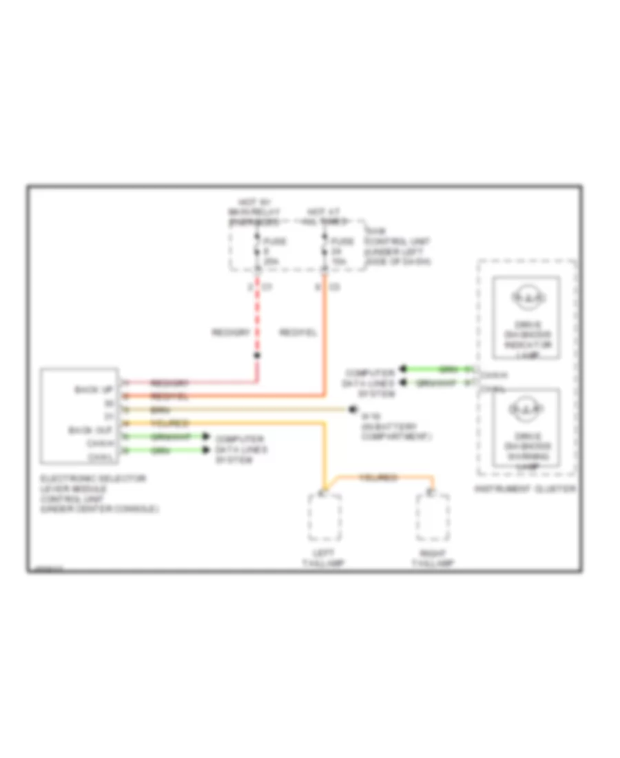
Backup Lamps Wiring Diagram for Smart Fortwo Passion 2014
List of elements for Backup Lamps Wiring Diagram for Smart Fortwo Passion 2014:
- (1.0l)
- (electric)
- (under center console) electronic selector lever module control unit
- 1.0l
- Automated manual transmission control unit (1.0l) (under driver's seat)
- Back
- Back out
- Back sup
- Backup
- Backup/ rear fog lamp
- Can h
- Can l
- Computer data lines system
- Electric
- Fuse 10a
- Fuse 25a
- Headlights system
- Hot at all times
- Hot w/ main relay energized
- Lamp
- Left taillamp
- Right taillamp
- Sam control unit (under left side of dash)
- W10 (in battery compt)
- W6 (left rear of trunk)
- W7 (right rear of trunk)
- X57/7
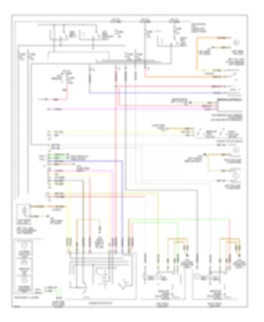
Exterior Lamps Wiring Diagram (1 of 2) for Smart Fortwo Passion 2014
List of elements for Exterior Lamps Wiring Diagram (1 of 2) for Smart Fortwo Passion 2014:
- (in battery compt) w10
- (near base of left "a" pillar) w9
- +bls
- +bs
- Can h
- Can l
- Center high mounted stop lamp
- Cockpit switch group
- Combination switch (on steering column)
- Computer data lines system
- Convertible
- Coupe
- Esp control unit (left center of vehicle undercarriage)
- Fuse 10a
- Fuse 125a
- Fuse 15a
- Fuse 7.5a
- Hazard warning flasher switch
- Headlights system
- Hot at all times
- Red
- Sam control unit (under left side of dash)
- Sam prefuse
- Standing lamps relay
- Stop lamp switch (on brake pedal assembly)
- W10 (in battery compt)
- W6 (left rear of trunk)
- X18/19-c1
- X23/7-c1
Exterior Lamps Wiring Diagram (2 of 2) for Smart Fortwo Passion 2014
List of elements for Exterior Lamps Wiring Diagram (2 of 2) for Smart Fortwo Passion 2014:
- (left rear of trunk) w6
- Backup lamp
- Backup lamps circuit
- Backup/rear fog lamp
- Can h
- Can l
- Computer data lines system
- Headlights system
- Instrument cluster
- Left additional turn signal lamp
- Left front lamp unit
- Left license plate lamp
- Left standing lamp
- Left taillamp
- Left turn signal indicator lamp
- Right additional turn signal lamp
- Right front lamp unit
- Right license plate lamp
- Right standing lamp
- Right taillamp
- Right turn signal indicator lamp
- Stop lamp
- Tail lamp
- Turn signal lamp
- W43 (left side of service compt)
- W6 (left rear of trunk)
- W7 (right rear of trunk)
- X57/7
GROUND DISTRIBUTION
Ground Distribution Wiring Diagram for Smart Fortwo Passion 2014
List of elements for Ground Distribution Wiring Diagram for Smart Fortwo Passion 2014:
- Blower motor relay 1 (electric), blower motor relay 2 (electric), cockpit switch group, stop lamp switch, esp control unit, power soft top switch, heater/ac operating unit electronic selector lever control module (electric), battery, interior socket sam control unit, alarm siren w/ inclination sensor & microwave sensor
- Blower switch (1.0l) & data link connector
- Brake vacuum pump (+), relay gear position sensor, power electronics control unit, on board charger 3kw, on board charger 22kw & electric refrigerant compressor
- Can ev bus node connector, vacuum pump (+) relay (electric), drivetrain control unit (electric), passenger head/thoraxbag sensor shield, weight sensing system (wss) control unit, right tail lamp, me-sfi (me) control unit (1.0l), fuel pump w/ fuel level sensor (1.0l), parking brake indicator switch, right turn signal lamp, right heated seat cushion, backup lamp relay, stop lamp relay & rear luggage carrier separation point
- Charger feed-in socket (w/ on board charger bkw)
- Driver door pressure sensor shield, front passenger door pressure sensor shield, high-voltage battery heater (electric) & ptc heater booster (hb (zh)) (electric)
- Electric
- Electric vehicle communication module control unit (electric), right steering wheel pitman arm (electric), left cockpit ambiance illumination, right cockpit ambiance illumination, center cockpit ambiance illumination, overhead control panel (ocp) ambiance illumination, rain sensor/light sensor (if equipped), combination switch, steering angle sensor, sam control unit, power window convenience feature control unit, instrument cluster, shutoff-capable interior lamp relay, right wiper switch, card reader on windshield, fanfare horn & air bag clock spring contact & front hs (sih) control unit
- Electric vehicle sound generator, electric drive & on board charger coolant pump, coolant fan motor wiper motor & sam control unit
- Fanfare horn system button, fanfare horn & air bag clock spring contact & left & right cruise control switch
- Heating system shutoff valve, right license plate lamp, driver head/thoraxbag sensor shield, left tail lamp, left license plate lamp, heated rear window, cylinder 1 ignition coil (1.0l), cylinder 2 ignition coil, cylinder 3 ignition coil (1.0l), center high mounted stop lamp, right roof cassette micro switch, soft top micro switch, left rear soft top micro switch, tailgate wiper motor (coupe), charge air fan motor (1.0l), rear end door handle switch, remote trunk opening switch (coupe), trunk lid rotary tumbler micro switch (convertible), trunk lid opening assist motor (convertible), trunk lid opening assist motor 1 (coupe), trunk lid opening assist motor 2 (coupe), battery management system control unit (electric) & stop top connector
- High voltage crash sensor control unit (electric)
- Left additional turn signal lamp, right additional turn signal lamp, left front lamp unit, right front lamp unit, left fog lamp (if equipped), right fog lamp (if equipped), left electrically adjustable & heated outside mirror, outside rearview mirror adjustment switch, right electrically adjustable & heated outside mirror, steering assist control unit, power steering torque sensor shield, right door rotary tumbler microswitch, left door rotary tumbler microswitch, wiper motor, horn, coolant fan motor (1.0l), right standing lamp, left standing lamp, brake fluid indicator switch, left door cl (zv) motor, driver door pocket ambiance illumination, front passenger door pocket ambiance illumination, right door cl (zv) motor, left power window switch & right power window switch
- Power steering motor shield
- Secondary air injection pump (1.0l)
- Smart entry radio, smart premium radio, coolant pump 1 (feed) (electric), coolant pump 2 (return) (electric), high-voltage ptc heater (electric) & sam control unit (electric)
- Subwoofer, turnrate & lateral acceleration sensor, sound amplifier, left backrest heated cushion & automated manual transmission control unit (1.0l)
- W10 (in battery compt)
- W11 (rear of engine)
- W11/5 (behind right rear bumper)
- W11/7 (on fuel filler neck)
- W110 (in steering wheel)
- W12
- W14 (left floor panel)
- W15/3 (electric)
- W26 (in battery compt)
- W30/2 (near power steering pump)
- W43 (left side of service compt)
- W49
- W6 (left rear of trunk)
- W7 (right rear of trunk)
- W83 (left front footwell)
- W9 (near base of left "a" pillar)
HEADLIGHTS
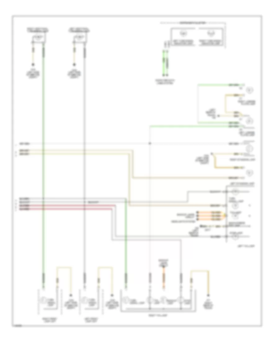
Headlights Wiring Diagram for Smart Fortwo Passion 2014
List of elements for Headlights Wiring Diagram for Smart Fortwo Passion 2014:
- (in battery compt) w10
- (near base of left "a" pillar) w9
- 125a
- Can h
- Can l
- Cockpit switch group
- Combination switch
- Computer data lines system
- Front fog lamp relay
- Front fog lamp switch
- Fuse
- Fuse 10a
- Fuse 15a
- Fuse 7.5a
- Headlamp range adjustment motor
- High beam
- High beam indicator lamp
- High beam relay
- Hot at all times
- Instrument cluster
- Left fog lamp (if equipped)
- Left front lamp unit
- Left rear fog lamp
- Left tail lamp (w/ rain sensor/ light sensor)
- Left tail lamp (w/o rain sensor/ light sensor)
- Low beam
- Low beam headlamp relay
- Low beam indicator lamp
- Rain sensor/light sensor (if equipped) (top center of windshield)
- Rear fog lamp ind
- Rear fog lamp relay
- Rear fog lamp switch
- Red
- Right fog lamp (if equipped)
- Right front lamp unit
- Sam control unit (under left side of dash)
- Sam prefuse
- W10 (in battery compt)
- W43 (left side of service compt)
- W6 (left rear of trunk)
- W9 (near base of left "a" pillar)
- X18/29-c1
HORN
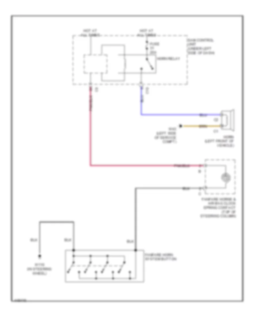
Horn Wiring Diagram for Smart Fortwo Passion 2014
List of elements for Horn Wiring Diagram for Smart Fortwo Passion 2014:
- C10
- Fanfare horn system button
- Fanfare horns & air bag clock spring contact (top of steering column)
- Fuse 20a
- Horn (left front of vehicle)
- Horn relay
- Hot at all times
- Sam control unit (under left side of dash)
- W110 (in steering wheel)
- W43 (left side of service compt)
INSTRUMENT CLUSTER
1.0L
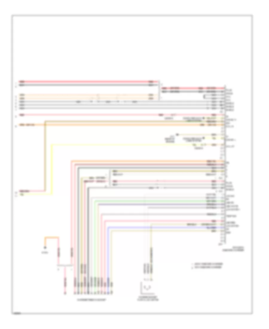
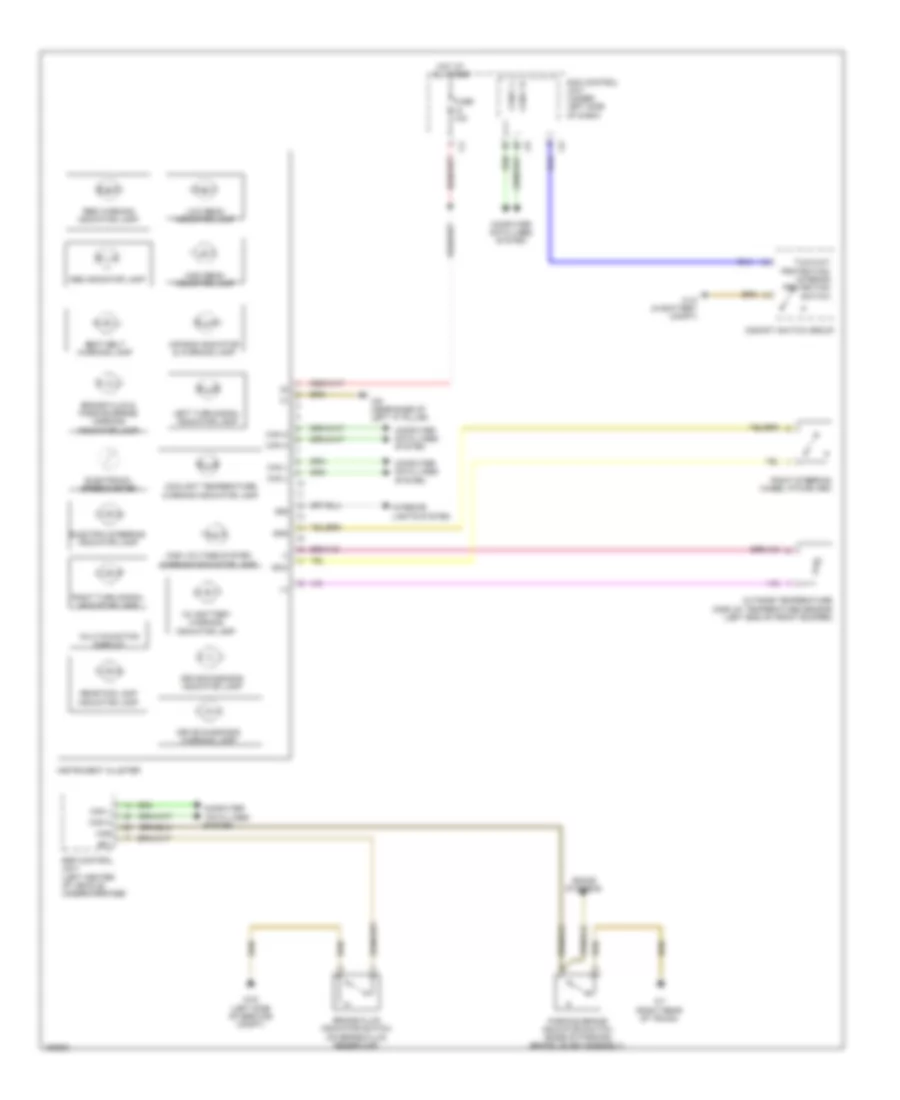
1.0L, Instrument Cluster Wiring Diagram for Smart Fortwo Passion 2014
List of elements for 1.0L, Instrument Cluster Wiring Diagram for Smart Fortwo Passion 2014:
- "check engine" mil indicator lamp
- (+)
- (-)
- -sal
- 58d
- Abs indicator lamp
- Ad/c
- Air bag indicator & warning lamp
- Alternator charge monitoring & warning indicator lamp
- Bfl
- Brake fluid & parking brake warning indicator lamp
- Brake fluid indicator switch (on brake fluid reservoir)
- Brightness sensor
- Can h
- Can l
- Can-c h
- Can-c l
- Cockpit switch group
- Computer
- Computer data lines system
- Coolant temperature warning indicator lamp
- Cruise control system
- Data lines
- Electric steering indicator lamp
- Electronic speedometer
- Engine controls system
- Esp control unit (left center of vehicle undercarriage)
- Esp warning indicator lamp
- Fuel pump w/ fuel level sensor (in fuel tank)
- Fuse 10a
- Gnd
- Gnd (sal)
- Has
- High beam indicator lamp
- Hot at all times
- Instrument cluster
- Instrument illumination
- Interior lights system
- Left turn signal indicator lamp
- Low beam indicator lamp
- M sens
- Me-sfi (me) control unit (right rear of luggage compt)
- Multi-function display
- Oil pressure warning lamp
- Outside temperature display temperature sensor (left end of front bumper)
- Parking brake indicator switch (base of parking brake lever assembly)
- Pnk
- Rear fog lamp indicator lamp
- Right turn signal indicator lamp
- Right wiper switch
- Sam control unit (under left side of dash)
- Seat belt warning lamp
- Sig
- Sound systems
- System
- Two-way protection/ interior protection switch
- W10 (in battery compt)
- W43 (left side of service compt)
- W7 (right rear of trunk)
- W9 (near base of left "a" pillar)
ELECTRIC
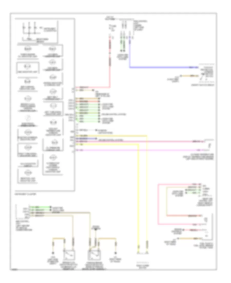
Electric, Instrument Cluster Wiring Diagram for Smart Fortwo Passion 2014
List of elements for Electric, Instrument Cluster Wiring Diagram for Smart Fortwo Passion 2014:
- (+)
- (-)
- 12v battery warning indicator lamp
- 58d
- Abs indicator lamp
- Ad/c
- Air bag indicator & warning lamp
- Bfl
- Brake fluid & parking brake warning indicator lamp
- Brake fluid indicator switch (on brake fluid reservoir)
- Can h
- Can l
- Can-c h
- Can-c l
- Cockpit switch group
- Computer
- Computer data lines system
- Coolant temperature warning indicator lamp
- Data lines
- Drive diagnosis indicator lamp
- Drive diagnosis warning lamp
- Electric steering indicator lamp
- Electronic speedometer
- Esp control unit (left center of vehicle undercarriage)
- Fuse 10a
- Gnd
- Has
- High beam indicator lamp
- High voltage system warning indicator lamp
- Hot at all times
- Instrument cluster
- Interior lights system
- Left turn signal indicator lamp
- Low beam indicator lamp
- Multi-function display
- Outside temperature display temperature sensor (left end of front bumper)
- Parking brake indicator switch (base of parking brake lever assembly)
- Rbs warning indicator lamp
- Rear fog lamp indicator lamp
- Right steering wheel pitman arm
- Right turn signal indicator lamp
- Sam control unit (under left side of dash)
- Seat belt warning lamp
- Sound systems
- System
- Two-way protection/ interior protection switch
- W10 (in battery compt)
- W43 (left side of service compt)
- W7 (right rear of trunk)
- W9 (near base of left "a" pillar)
INTERIOR LIGHTS
Interior Lights Wiring Diagram for Smart Fortwo Passion 2014
List of elements for Interior Lights Wiring Diagram for Smart Fortwo Passion 2014:
- (left side of service compt) w43
- 1.0l
- 58d
- C10
- Center cockpit ambiance illumination
- Close soft top relay (left side of luggage compt)
- Cockpit switch group
- Driver door pocket ambiance illumination
- Electric
- Fanfare horns & air bag clock spring contact (top of steering column)
- Front interior lamp (1.0l)
- Front interior lamp (electric)
- Front passenger door pocket ambiance illumination
- Fuse 10a
- Fuse 15a
- Fuse 5a
- Heating & air conditioning operating unit (center of dash)
- Hot at all times
- Instrument cluster
- Instrument illumination
- Interior lamp switch
- Left cockpit ambiance illumination
- Left cruise control switch (if equipped)
- Left door rotary tumbler micro switch
- Left front footwell lamp
- Left power window switch
- Nca
- Open soft top relay (left side of luggage compt)
- Overhead control panel (ocp) ambiance illumination
- Right cockpit ambiance illumination
- Right cruise control switch (if equipped)
- Right door rotary tumbler micro switch
- Right front footwell lamp
- Right power window driver side switch
- Right power window passenger side switch
- Sam control unit (under left side of dash)
- Shutoff-capable interior lamp relay (w/ interior light package)
- Smart entry radio/ premium radio
- W10 (in battery compt)
- W110 (in steering wheel)
- W12
- W43 (left side of service compt)
- W9 (near base of left "a" pillar)
- X35/1
- X35/2
NAVIGATION
Navigation Wiring Diagram, with Amplifier for Smart Fortwo Passion 2014
List of elements for Navigation Wiring Diagram, with Amplifier for Smart Fortwo Passion 2014:
- (+)
- (-)
- (not used)
- (under driver's seat) automated manual transmission control unit
- (w/ external audio source)
- 1.0l
- 58d
- Ant
- Electric
- Esp control unit (left center of vehicle undercarriage)
- Ev2
- External audio source separation point (if equipped)
- Fuse 10a
- Fuse 15a
- Fuse r6 40a
- Gps antenna (center of dash)
- Has
- Hot at all times
- Hot in on or start
- Interior lights system
- Interior/engine connector (electric)
- Left door sound system tweeter
- Left door sound system woofer
- Left rear speaker
- Left tweeter
- Lin gnd
- Lin in
- Nca
- Park sw
- Parking brake indicator switch (base of parking brake lever assembly)
- Pnk
- Radio antenna
- Red
- Right door sound system tweeter
- Right door sound system woofer
- Right rear speaker
- Right tweeter
- Sam control unit (under left side of dash)
- Shield
- Sig
- Smart premium radio
- Sound amplifier (right end of dash)
- Subwoofer
- Sw out ant
- Transmissions system
- Usb +
- Usb -
- Usb bus
- Usb connection connector
- Usb gnd
- W/ ece
- W/o ece & interior/engine connector
- W/o ece w/ interior/engine connector
- W12
- W14 (left floor panel)
- W7 (right rear of trunk)
- X134/1
- X134/2
- X26/8
- X35/1
- X35/2
Navigation Wiring Diagram, without Amplifier for Smart Fortwo Passion 2014
List of elements for Navigation Wiring Diagram, without Amplifier for Smart Fortwo Passion 2014:
- (+)
- (-)
- (under driver's seat) automated manual transmission control unit
- (w/ external audio source)
- 1.0l
- 58d
- Ant
- Electric
- Esp control unit (left center of vehicle undercarriage)
- Ev2
- External audio source separation point (if equipped)
- Fuse 10a
- Fuse 15a
- Fuse r6 40a
- Gps antenna (center of dash)
- Has
- Hot at all times
- Hot in on or start
- Interior lights system
- Interior/engine connector (electric)
- Left door sound system tweeter
- Left door sound system woofer
- Left rear speaker
- Left tweeter
- Lin gnd
- Lin in
- Nca
- Park sw
- Parking brake indicator switch (base of parking brake lever assembly)
- Pnk
- Radio antenna
- Red
- Right door sound system tweeter
- Right door sound system woofer
- Right rear speaker
- Right tweeter
- Sam control unit (under left side of dash)
- Shield
- Sig
- Smart premium radio
- Subwoofer
- Transmissions system
- Usb +
- Usb -
- Usb bus
- Usb connection connector
- Usb gnd
- W/ ece
- W/o ece & interior/engine connector
- W/o ece w/ interior/engine connector
- W12
- W14 (left floor panel)
- W7 (right rear of trunk)
- X134/1
- X134/2
- X26/8
- X35/1
- X35/2
POWER DISTRIBUTION
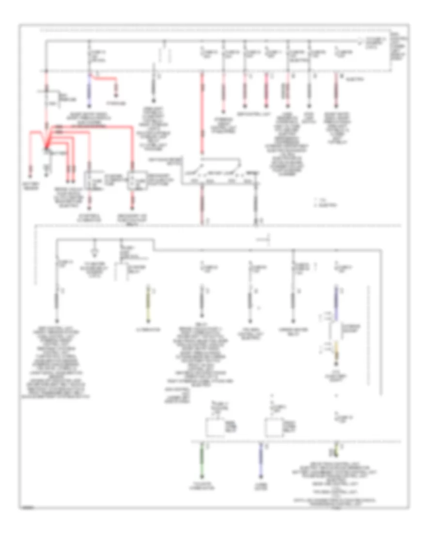
Power Distribution Wiring Diagram (1 of 2) for Smart Fortwo Passion 2014
List of elements for Power Distribution Wiring Diagram (1 of 2) for Smart Fortwo Passion 2014:
- (in battery compt)
- 1.0l
- 125a
- Acc
- Alternator
- Battery
- Battery sensor
- Brake vacuum pump (bvp) & 12v ptc heater booster fuse (electric)
- Card reader on windshield, high voltage ptc heater, electric refrigerant compressor, interior compartment electric expansion valve & electric drive motor on board charger coolant pump on board charger
- Drive train control unit, electric vehicle sound generator, battery management system control unit, power electronics control unit, (electric) me-sfi (me) control unit, (1.0l) tpm (rdk) control unit, (1.0l) data link connector & automated manual transmission control unit (1.0l)
- Electric
- Esp control unit
- Esp control unit, weight sensing system (wss) control unit, steering assist control unit, restraint systems control unit, turn rate & lateral acceleration sensor, steering angle sensor, yaw rate, lateral & longitudinal acceleration sensor, air bag off indicator lamp, driver side seat belt buckle restraint systems switch & front passenger seat belt buckle restraint systems switch
- Front wiper relay
- Fuse 1 25a (or 15 a)
- Fuse 11 25a
- Fuse 15 15a (or 40a)
- Fuse 17 (coupe) 15a
- Fuse 18 10a
- Fuse 19 7.5a
- Fuse 2 25a
- Fuse 20 10a
- Fuse 200a
- Fuse 21 15a
- Fuse 33 50a
- Fuse 34 40a
- Fuse 35 30a
- Fuse 50a
- Fuse r1 fuse 36 7.5a
- Fuse r2 7.5a
- Fuse r4 7.5a
- Fuse r5 10a (electric)
- Fuse r6 40a
- Ignition/starter switch
- Interior socket
- Lock
- Mirror heater relay
- Open soft top relay, close soft top relay, front interior lamp & shutoff-capable interior lamp relay (w/ inter light package)
- Pyrofuse
- Rear wiper relay
- Red
- Red/pnk
- Relay brake vacuum pump (-), right wiper switch, power soft top switch, electronic selector lever module control module, smart entry radio, smart premium radio, outside rearview mirror adjustment switch, front hs (sih) control unit, heater & air conditioning operating unit & right steering wheel pitman arm (electric)
- Run
- Sam control unit (under left side of dash)
- Sam prefuse
- Secondary air injection pump fuse
- Secondary air injection pump relay
- Smart entry radio smart premium radio & sub woofer (w/ sound system)
- Smart entry radio, smart premium radio open soft top relay & closed soft top relay
- Start
- Starter & alternator
- Starter relay
- Starter/ alternator fuse
- Steering assist control unit (if equipped)
- Stop lamp switch
- Tailgate wiper motor
- To fuse 12 (diagram 2 of 2)
- To heater blower relay (diagram 2 of 2)
- Tpm (rdk) control unit (electric)
- W10
- Wiper motor
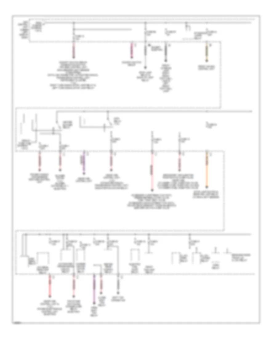
Power Distribution Wiring Diagram (2 of 2) for Smart Fortwo Passion 2014
List of elements for Power Distribution Wiring Diagram (2 of 2) for Smart Fortwo Passion 2014:
- Automated transmission manual relay
- Blower motor (1.0l) blower motor relay 1 (electric)
- Charge air fan motor relay
- Cl (zv) locked relay
- Cl (zv) open relay
- Close soft top relay
- Cockpit switch group
- Cockpit switch group, combination switch, tpm (rdk) control unit, rain sensor/light sensor (if equipped), data link connector, automated manual transmission control unit, instrument cluster, (1.0l) right turn signal/stop lamp relay & left turn signal/stop lamp relay
- Electric fuel pump relay
- Except electric
- Fan stage switching change over relay (electric)
- From a fuse r6 (diagram 1 of 2)
- From fuse 18 b (diagram 1 of 2)
- Front fog lamp relay
- Front hs (sih) control unit
- Front interior lamp, right front foot well lamp & left front foot well lamp,
- Fuse 10 15a
- Fuse 12 10a
- Fuse 14 15a
- Fuse 16 15a
- Fuse 24 15a
- Fuse 27 7.5a
- Fuse 28 40a
- Fuse 29 30a
- Fuse 3 20a
- Fuse 30 40a
- Fuse 31 20a
- Fuse 4 25a
- Fuse 44 25a
- Fuse 5 10a
- Fuse 8 25a
- Fuse 9 7.5a
- Fuse r6 15a
- Fuse r7 5a
- Heated rear window relay
- Heater blower relay
- High beam relay
- Horn relay
- Low beam headlamp relay
- Main relay (1.0l)
- Me-sfi (me) control unit
- Me-sfi (me) control unit & (1.0l) power electronics control unit (electric)
- Me-sfi (me) control unit, (1.0l) automated manual transmission control unit, radiator fan motor relay,
- O2 sensor 1(upstream twc (fat)), pressure regulator valve, fuel tank vent valve, o2 sensor 2 (down stream twc (kat)), adjustable camshaft timing solenoid & egr (arf) switch over valve
- Open soft top relay
- Power window convenience feature control unit
- Rear end door/ trunk lid cl (zv) relay
- Red
- Sam control unit (under left side of dash)
- Secondary air injection pump switch over valve, me-sfi (me), cylinder 1 fuel injection valve, cylinder 2 fuel injection valve & cylinder 3 fuel injection valve
- Soft top connector
- Standing lamps relay
- Stop lamp relay & back up lamp relay
- Stop lamp switch & rear fog lamp relay (w/ rain/light sensor)
POWER DOOR LOCKS
Power Door Locks Wiring Diagram (1 of 2) for Smart Fortwo Passion 2014
List of elements for Power Door Locks Wiring Diagram (1 of 2) for Smart Fortwo Passion 2014:
- C10
- Can c h
- Can c l
- Central
- Cl (zv) locked relay
- Cl (zv) open relay
- Clk
- Computer data lines system
- Data
- Exterior lights system
- Fuel filler flap cl (zv) motor (behind right rear body panel)
- Fuse 10a
- Fuse 20a
- Gnd
- Horn relay
- Horns system
- Hot at all times
- Left door cl (zv) motor & left door rotary tumbler micro switch
- Lin 2
- Lock
- Parking light
- Pnk
- Rear end door/trunk lid cl (zv) relay
- Right door cl (zv) motor & right door rotary tumbler micro switch
- Sam control unit (under left side of dash)
- Sig
- Tail gate rly out
- U central
- Unlock
- W43 (left side of service compt)
- W9 (near base of left "a" pillar)
- X35/1
- X35/2
Power Door Locks Wiring Diagram (2 of 2) for Smart Fortwo Passion 2014
List of elements for Power Door Locks Wiring Diagram (2 of 2) for Smart Fortwo Passion 2014:
- (in battery compt) w10
- (under center console) (w/ ata (edw) & siren) microwave sensor
- Alarm siren w/ inclination sensor (w/ ata (edw) & siren) (under left side of vehicle)
- Cockpit switch group
- Convertible
- Coupe
- Inside lock cl (zv) switch
- Inside unlock cl (zv) switch
- Pnk
- Rear end door handle switch
- Remote trunk opening switch
- Transponder coil (under electronic selector lever)
- Trunk lid opening assist motor
- Trunk lid opening assist motor 1
- Trunk lid opening assist motor 2 (coupe)
- Trunk lid rotary tumbler micro switch
- W10 (in battery compt)
- W6 (left rear of trunk)
POWER MIRRORS
Power Mirrors Wiring Diagram for Smart Fortwo Passion 2014
List of elements for Power Mirrors Wiring Diagram for Smart Fortwo Passion 2014:
- Adjustment motor
- Defogger system
- Fuse 10a
- Hot in on or start
- Left electrically adjustable & heated outside mirror
- Mirror heater
- Mirror in/out m
- Mirror up/down adjustment motor
- Nca
- Outside rearview mirror adjustment switch
- Right electrically adjustable & heated outside mirror
- Sam control unit (under left side of dash)
- W43 (left side of service compt)
- X35/1
- X35/2
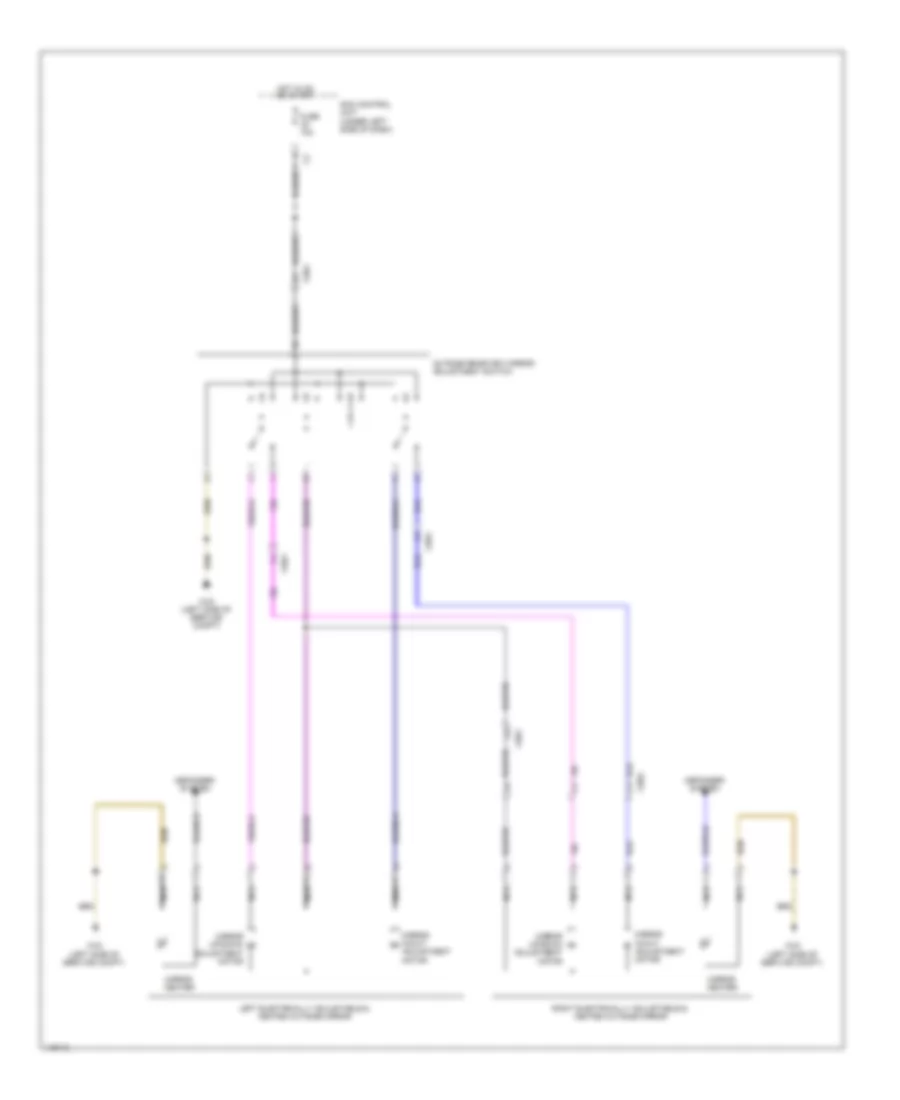
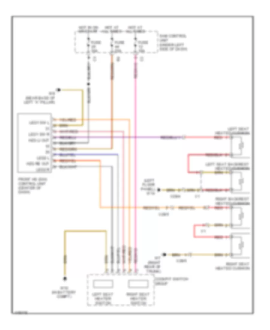
POWER SEATS
Power Seats Wiring Diagram for Smart Fortwo Passion 2014
List of elements for Power Seats Wiring Diagram for Smart Fortwo Passion 2014:
- (left floor panel) w14
- Cockpit switch group
- Front hs (sih) control unit (center of dash)
- Fuse 10a
- Fuse 25a
- Hot at all times
- Hot in on or start
- Hzg li out
- Hzg re out
- Led1 sw l
- Led1 sw r
- Led2 l
- Led2 r
- Left seat backrest heated cushion
- Left seat heated cushion
- Left seat heater switch
- Red
- Right backrest heated cushion
- Right seat heated cushion
- Right seat heater switch
- Sam control unit (under left side of dash)
- W10 (in battery compt)
- W7 (right rear of trunk)
- W9 (near base of left "a" pillar)
- X28/4
- X28/5
POWER TOP/SUNROOF
Power Top/Sunroof Wiring Diagram for Smart Fortwo Passion 2014
List of elements for Power Top/Sunroof Wiring Diagram for Smart Fortwo Passion 2014:
- (left side of luggage compt) close soft top relay
- (left side of luggage compt) open soft top relay
- (near base of left "a" pillar) w9
- Can ch
- Can cl
- Computer data lines system
- Electric soft top motor (in luggage compt)
- Folding top in
- Folding top selector
- Folding top sw1 in
- Folding top sw2 in
- Folding top sw3 in
- Fuse 10a
- Fuse 15a
- Fuse 30a
- Gnd
- Hot at all times
- Hot in on or start
- Left rear soft top microswitch (on left soft top drive mechanism)
- Left roof cassette microswitch
- Left soft top drive (on left soft top drive mechanism)
- Power soft top switch
- Right rear soft top microswitch (on right soft top drive mechanism)
- Right roof cassette microswitch (top of right "b" pillar)
- Right soft top drive (on right soft top drive mechanism)
- Sam control unit (under left side of dash)
- Soft top microswitch (top of right "b" pillar)
- W10 (in battery compt)
- W6 (left rear of trunk)
- X23/7-c1
- X23/7-c2
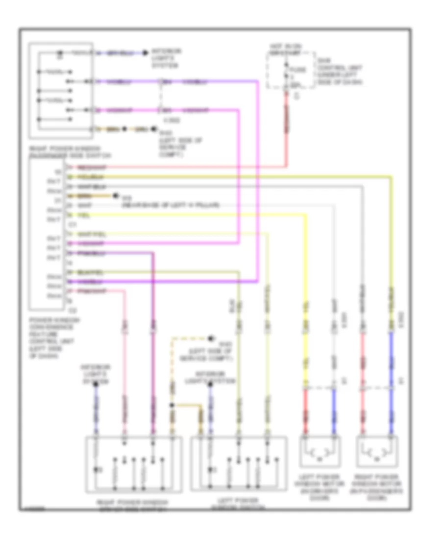
POWER WINDOWS
Power Windows Wiring Diagram for Smart Fortwo Passion 2014
List of elements for Power Windows Wiring Diagram for Smart Fortwo Passion 2014:
- Fh h
- Fh t
- Fuse 20a
- Hot in on or start
- Interior lights system
- Left power window motor (in driver's door)
- Left power window switch
- Power window convenience feature control unit (left side of dash)
- Red
- Right power window driver side switch
- Right power window motor (in passenger's door)
- Right power window passenger side switch
- Sam control unit (under left side of dash)
- W43 (left side of service compt)
- W9 (near base of left 'a' pillar)
- X35/1
- X35/2
RADIO
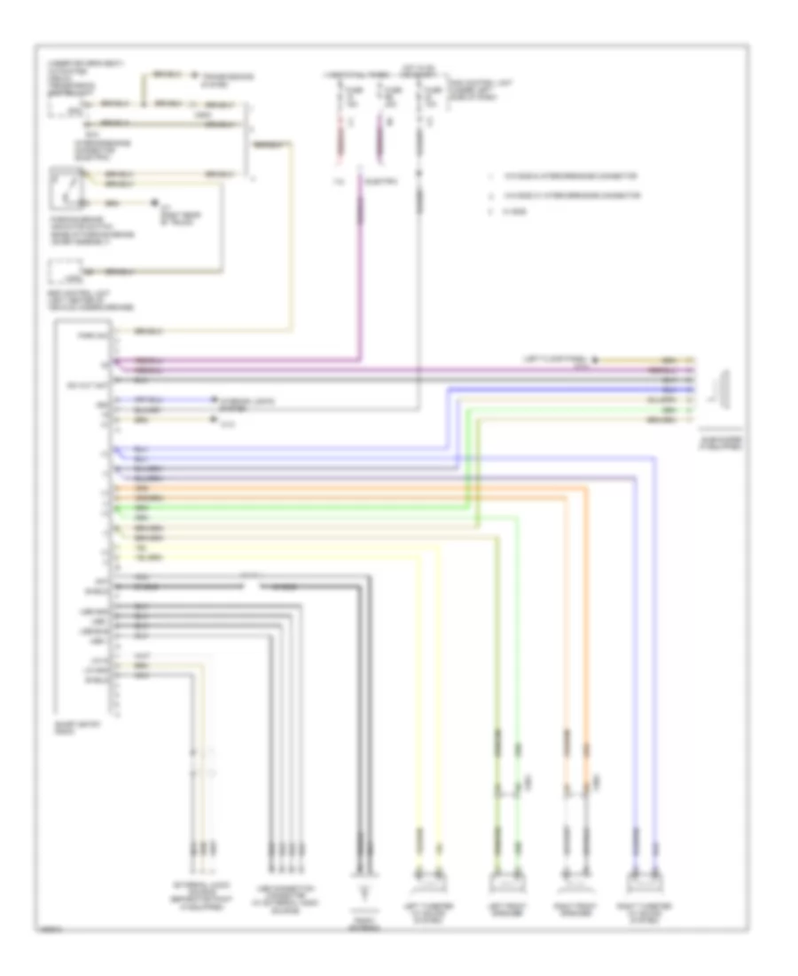
Base Radio Wiring Diagram for Smart Fortwo Passion 2014
List of elements for Base Radio Wiring Diagram for Smart Fortwo Passion 2014:
- (+)
- (-)
- (left floor panel) w14
- (under driver's seat) automated manual transmission control unit
- 1.0l
- 58d
- Ant
- Electric
- Esp control unit (left center of vehicle undercarriage)
- Ev2
- External audio source separation point (if equipped)
- Fuse 10a
- Fuse 15a
- Fuse r6 40a
- Has
- Hot at all times
- Hot in on or start
- Interior lights system
- Interior/engine connector (electric)
- Left front speaker
- Left tweeter (w/ sound system)
- Lin gnd
- Lin in
- Nca
- Park sw
- Parking brake indicator switch (base of parking brake lever assembly)
- Radio antenna
- Right front speaker
- Right tweeter (w/ sound system)
- Sam control unit (under left side of dash)
- Shield
- Sig
- Smart entry radio
- Subwoofer (if equipped)
- Sw out ant
- Transmissions system
- Usb +
- Usb -
- Usb bus
- Usb connection connector (w/ external audio source)
- Usb gnd
- W/ ece
- W/o ece & interior/engine connector
- W/o ece w/ interior/engine connector
- W12
- W7 (right rear of trunk)
- X26/8
- X35/1
- X35/2
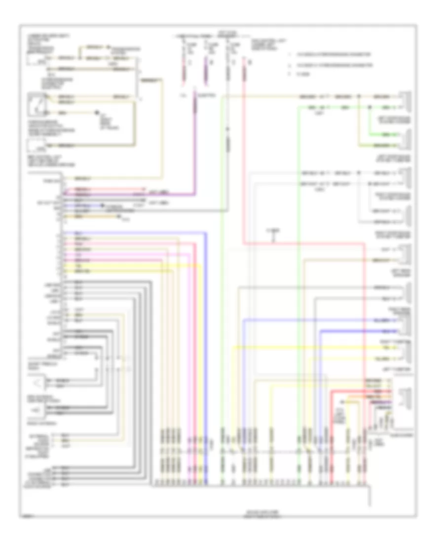
Premium Radio Wiring Diagram, with Amplifier for Smart Fortwo Passion 2014
List of elements for Premium Radio Wiring Diagram, with Amplifier for Smart Fortwo Passion 2014:
- (+)
- (-)
- (not used)
- (under driver's seat) automated manual transmission control unit
- (w/ external audio source)
- 1.0l
- 58d
- Ant
- Electric
- Esp control unit (left center of vehicle undercarriage)
- Ev2
- External audio source separation point (if equipped)
- Fuse 10a
- Fuse 15a
- Fuse r6 40a
- Gps antenna (center of dash)
- Has
- Hot at all times
- Hot in on or start
- Interior lights system
- Interior/engine connector (electric)
- Left door sound system tweeter
- Left door sound system woofer
- Left rear speaker
- Left tweeter
- Lin gnd
- Lin in
- Nca
- Park sw
- Parking brake indicator switch (base of parking brake lever assembly)
- Pnk
- Radio antenna
- Red
- Right door sound system tweeter
- Right door sound system woofer
- Right rear speaker
- Right tweeter
- Sam control unit (under left side of dash)
- Shield
- Sig
- Smart premium radio
- Sound amplifier (right end of dash)
- Subwoofer
- Sw out ant
- Transmissions system
- Usb +
- Usb -
- Usb bus
- Usb connection connector
- Usb gnd
- W/ ece
- W/o ece & interior/engine connector
- W/o ece w/ interior/engine connector
- W12
- W14 (left floor panel)
- W7 (right rear of trunk)
- X134/1
- X134/2
- X26/8
- X35/1
- X35/2
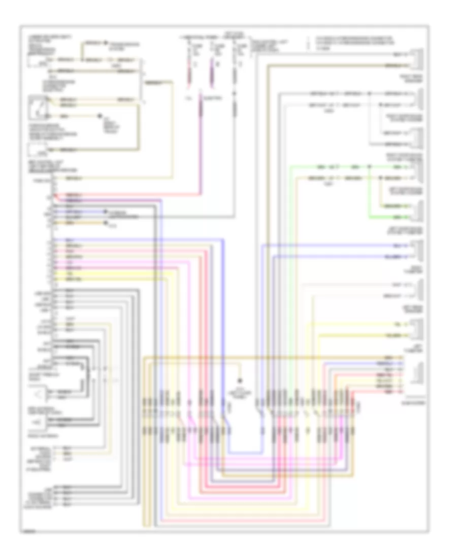
Premium Radio Wiring Diagram, without Amplifier for Smart Fortwo Passion 2014
List of elements for Premium Radio Wiring Diagram, without Amplifier for Smart Fortwo Passion 2014:
- (+)
- (-)
- (under driver's seat) automated manual transmission control unit
- (w/ external audio source)
- 1.0l
- 58d
- Ant
- Electric
- Esp control unit (left center of vehicle undercarriage)
- Ev2
- External audio source separation point (if equipped)
- Fuse 10a
- Fuse 15a
- Fuse r6 40a
- Gps antenna (center of dash)
- Has
- Hot at all times
- Hot in on or start
- Interior lights system
- Interior/engine connector (electric)
- Left door sound system tweeter
- Left door sound system woofer
- Left rear speaker
- Left tweeter
- Lin gnd
- Lin in
- Nca
- Park sw
- Parking brake indicator switch (base of parking brake lever assembly)
- Pnk
- Radio antenna
- Red
- Right door sound system tweeter
- Right door sound system woofer
- Right rear speaker
- Right tweeter
- Sam control unit (under left side of dash)
- Shield
- Sig
- Smart premium radio
- Subwoofer
- Transmissions system
- Usb +
- Usb -
- Usb bus
- Usb connection connector
- Usb gnd
- W/ ece
- W/o ece & interior/engine connector
- W/o ece w/ interior/engine connector
- W12
- W14 (left floor panel)
- W7 (right rear of trunk)
- X134/1
- X134/2
- X26/8
- X35/1
- X35/2
STARTING/CHARGING
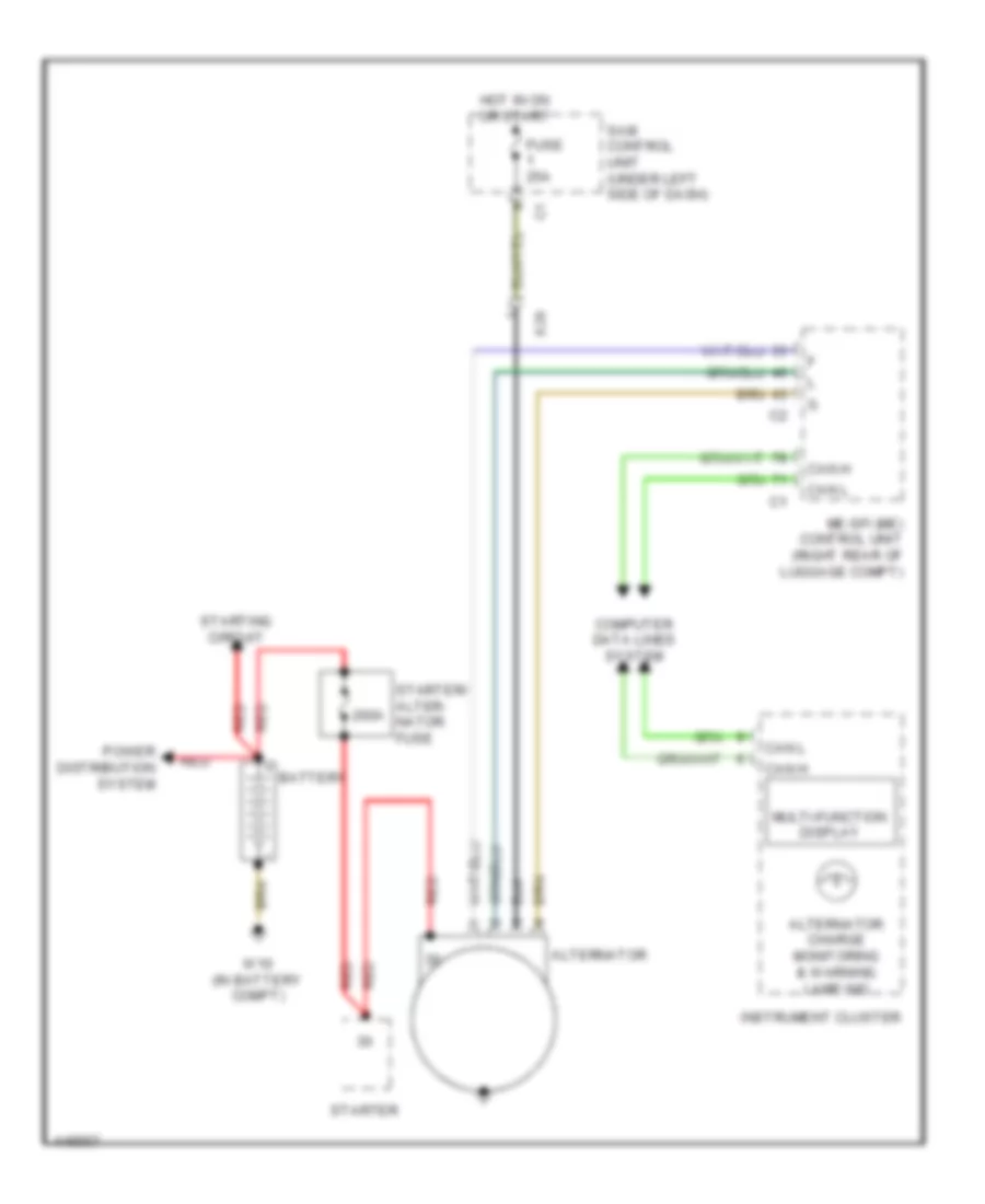
Charging Wiring Diagram for Smart Fortwo Passion 2014
List of elements for Charging Wiring Diagram for Smart Fortwo Passion 2014:
- 200a
- Alternator
- Alternator charge monitoring & warning lamp ind
- Battery
- Can h
- Can l
- Computer data lines system
- Fuse 25a
- Hot in on or start
- Instrument cluster
- Me-sfi (me) control unit (right rear of luggage compt)
- Multi-function display
- Power distribution system
- Red
- Sam control unit (under left side of dash)
- Starter
- Starter/ alter- nator fuse
- Starting circuit
- W10 (in battery compt)
- X26
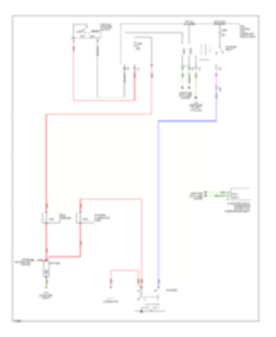
Starting Wiring Diagram for Smart Fortwo Passion 2014
List of elements for Starting Wiring Diagram for Smart Fortwo Passion 2014:
- 125a
- 200a
- Acc
- Alternator
- Automated manual transmission control unit (under driver's seat)
- Battery
- Can h
- Can l
- Can-h
- Can-l
- Computer data lines system
- Fuse 25a
- Fuse 50a
- Hot at all times
- Hot in on or start
- Ignition/ starter switch
- Lock
- Power distribution system
- Red
- Run
- Sam control unit (under left side of dash)
- Sam prefuse
- Start
- Starter
- Starter relay
- Starter/ alternator fuse
- W10 (in battery compt)
- W9 (near base of left "a" pillar)
- X26
SUPPLEMENTAL RESTRAINTS
Supplemental Restraints Wiring Diagram (1 of 2) for Smart Fortwo Passion 2014
List of elements for Supplemental Restraints Wiring Diagram (1 of 2) for Smart Fortwo Passion 2014:
- (in battery compt) w26
- (in driver door) driver door pressure sensor
- (in front passenger door) front passenger door pressure sensor
- Belt tension sensor (in seat belt anchor)
- Can h
- Can l
- Computer data lines system
- D belt+
- D belt-
- D tensi+
- D tensi-
- D wbag+
- D wbag-
- Driver belt force limiter
- Driver seat adjustment detection sensor
- Driver seat belt buckle restraint systems switch
- Driver side anchor fitting tensioner squib
- Front passenger seat belt buckle restraint systems switch
- Fuse 10a
- Gnd
- Hot in run or start
- Left window bag squib (if equipped)
- Nca
- P wbag+
- P wbag-
- Pnk
- Pyrofuse (center rear of console)
- Red
- Restraints systems control unit (center of dash)
- Right window bag squib (if equipped)
- Sam control unit (under left side of dash)
- Seat occupied recognition pressure sensor (in seat bottom)
- Sig
- Stps
- Stps dat
- Vref
- W7 (right rear of trunk)
- W83 (left front footwell)
- Weight sensing system (wss) control unit (under seat)
- X28/10
- X28/8
- X28/9
- X35/1
- X35/2
- X55/4
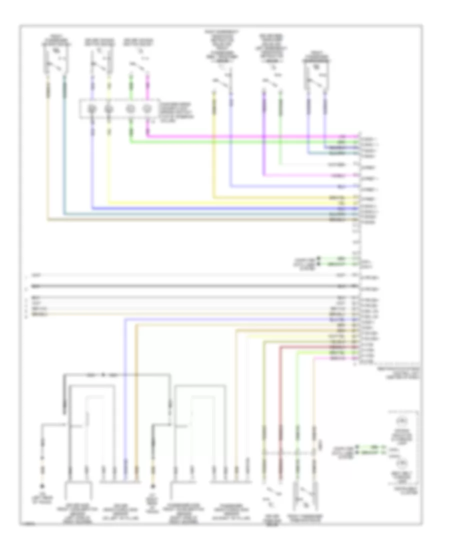
Supplemental Restraints Wiring Diagram (2 of 2) for Smart Fortwo Passion 2014
List of elements for Supplemental Restraints Wiring Diagram (2 of 2) for Smart Fortwo Passion 2014:
- Air bag indicator & warning lamp
- Can h
- Can l
- Can-h
- Can-l
- Computer data lines system
- D bag 1 +
- D bag 1 -
- D bag 2 +
- D bag 2 -
- D bkl on
- D pr dsi+
- D-ds1+
- D-ds1-
- D-pret +
- D-pret-
- Driver air bag ignition squib 1
- Driver air bag ignition squib 2
- Driver head/thorax bag sensor (on left "b" pillar)
- Driver knee bag squib
- Driver reel tensioner squib (or) left emergency tensioning retractor squib
- Driver side front acceleration sensor (left side of front bumper)
- Fanfare horns/ air bag clock spring contact (top of steering column)
- Front passenger air bag squib 1
- Front passenger air bag squib 2
- Front passenger knee bag squib
- Instrument cluster
- Nca
- P bag1+
- P bag1-
- P bag2+
- P bag2-
- P bkl on
- P htb+
- P htb-
- P pr dsi+
- P pr dsi-
- P sa dsi+
- P sa dsi-
- P-pret +
- P-pret -
- Passenger head/thorax bag sensor (on right "b" pillar)
- Passenger side front acceleration sensor (right side of front bumper)
- Restraints systems control unit (center of dash)
- Right emergency tensioning retractor squib (or) front passenger reel tensioner squib
- Seat belt warning lamp
- W6 (left rear of trunk)
- W7 (right rear of trunk)
- X99/17
TRANSMISSION
1.0L
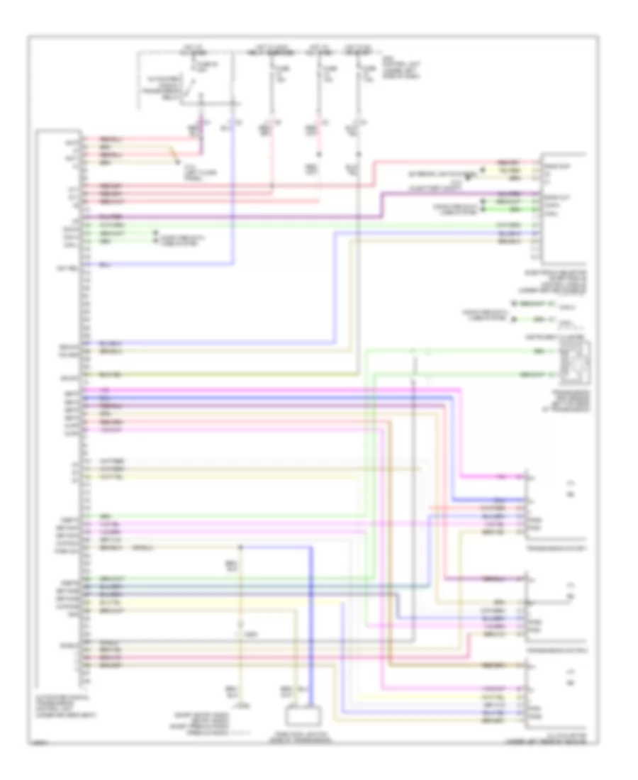
1.0L, Transmission Wiring Diagram for Smart Fortwo Passion 2014
List of elements for 1.0L, Transmission Wiring Diagram for Smart Fortwo Passion 2014:
- (-)
- (under driver's seat)
- 87/1
- Amt rel
- Amt1
- Amt2
- Automated manual transmission
- Automated manual transmission control unit
- Back out
- Back sup
- Can h
- Can l
- Clutch motor (under left rear of vehicle)
- Computer data lines system
- Down
- Electronic selector lever module control module (under center console)
- Eswma
- Exterior lights system
- Fuse 10a
- Fuse 15a
- Fuse 30 40a
- Fuse 7.5a
- Getinka
- Getinkb
- Getm
- Getp
- Gnd
- Hot at all times
- Hot in on or start
- Hot w/ main relay energized
- Ign sw
- Instrument cluster
- Kupinka
- Kupinkb
- Kupm
- Kupp
- Ngeta
- Ngetb
- Park pawl switch (side of transmission)
- Park sw
- Pos1
- Pos2
- Relay
- Sam control unit (under left side of dash)
- Shield
- Smart entry radio (entry radio) smart premium radio (premium radio)
- Transmission motor 1
- Transmission motor 2
- Transmission rpm sensor (bottom rear of transmission)
- W10 (in battery compt)
- W14 (left floor panel)
- Ws gnd
- X26/8
ELECTRIC
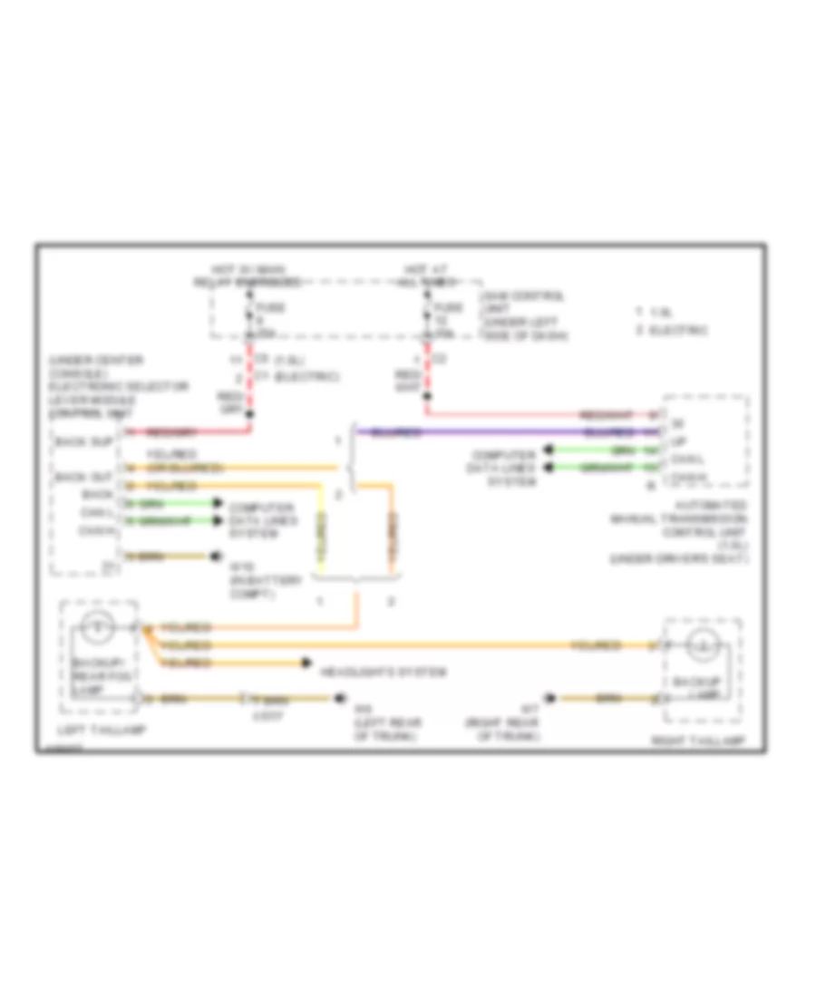
Electric, Transmission Wiring Diagram for Smart Fortwo Passion 2014
List of elements for Electric, Transmission Wiring Diagram for Smart Fortwo Passion 2014:
- Back out
- Back up
- Can h
- Can l
- Computer data lines system
- Drive diagnosis indicator lamp
- Drive diagnosis warning lamp
- Electronic selector lever module control unit (under center console)
- Fuse 15a
- Fuse 25a
- Hot at all times
- Hot w/ main relay energized
- Instrument cluster
- Left taillamp
- Right taillamp
- Sam control unit (under left side of dash)
- W10 (in battery compartment)
TRUNK, TAILGATE, FUEL DOOR
1.0L
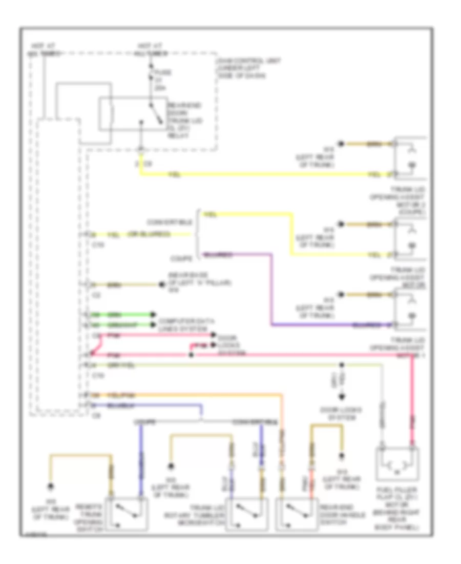
1.0L, Trunk & Fuel Door Release Wiring Diagram for Smart Fortwo Passion 2014
List of elements for 1.0L, Trunk & Fuel Door Release Wiring Diagram for Smart Fortwo Passion 2014:
- (near base of left "a" pillar) w9
- C10
- Computer data lines system
- Convertible
- Coupe
- Door locks system
- Fuel filler flap cl (zv) motor (behind right rear body panel)
- Fuse 20a
- Hot at all times
- Pnk
- Rear-end door handle switch
- Rear-end door/ trunk lid cl (zv) relay
- Remote trunk opening switch
- Sam control unit (under left side of dash)
- Trunk lid opening assist motor
- Trunk lid opening assist motor 1
- Trunk lid opening assist motor 2 (coupe)
- Trunk lid rotary tumbler microswitch
- W6 (left rear of trunk)
ELECTRIC
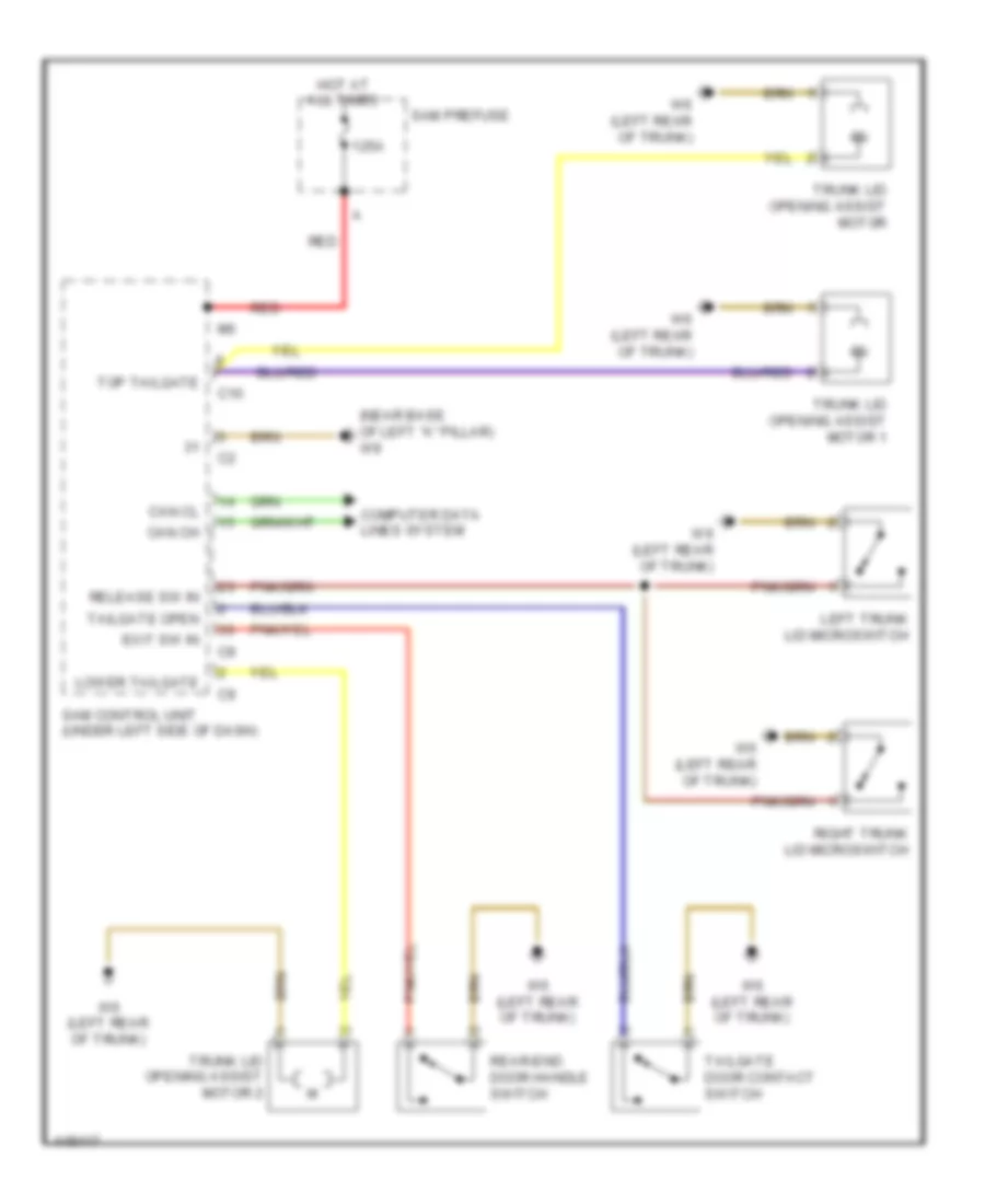
Electric, Trunk Release Wiring Diagram for Smart Fortwo Passion 2014
List of elements for Electric, Trunk Release Wiring Diagram for Smart Fortwo Passion 2014:
- (near base of left "a" pillar) w9
- 125a
- C10
- Can ch
- Can cl
- Computer data lines system
- Exit sw in
- Hot at all times
- Left trunk lid microswitch
- Lower tailgate
- Rear-end door handle switch
- Red
- Release sw in
- Right trunk lid microswitch
- Sam control unit (under left side of dash)
- Sam prefuse
- Tailgate door contact switch
- Tailgate open
- Top tailgate
- Trunk lid opening assist motor
- Trunk lid opening assist motor 1
- Trunk lid opening assist motor 2
- W6 (left rear of trunk)
WARNING SYSTEMS
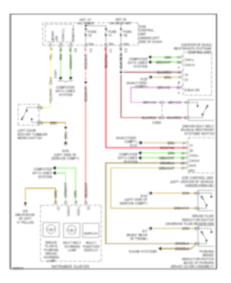
Seat Belt Warning Wiring Diagram for Smart Fortwo Passion 2014
List of elements for Seat Belt Warning Wiring Diagram for Smart Fortwo Passion 2014:
- (center of dash) restraints systems control unit
- (in battery compt) w10
- 10a
- 25a
- Bfl
- Brake fluid & parking brake warning lamp
- Brake fluid indicator switch (on brake fluid reservoir)
- Can h
- Can l
- Can-c h
- Can-c l
- Computer data lines system
- Display
- Driver seat belt buckle restraint systems switch
- Esp control unit (left center of vehicle undercarriage)
- Fuse
- Has
- Hot at all times
- Hot in on or start
- Instrument cluster
- Left door rotary tumbler micro switch
- Multi- function display
- Parking brake indicator switch (base of parking brake lever assembly)
- Red/pnk
- Sam control unit (under left side of dash)
- Seat belt warning lamp
- Sound systems
- Sw micro
- W26 (in battery compt)
- W43 (left side of service compt)
- W7 (right rear of trunk)
- W9 (near base of left "a" pillar)
- X28/8
- X35/1
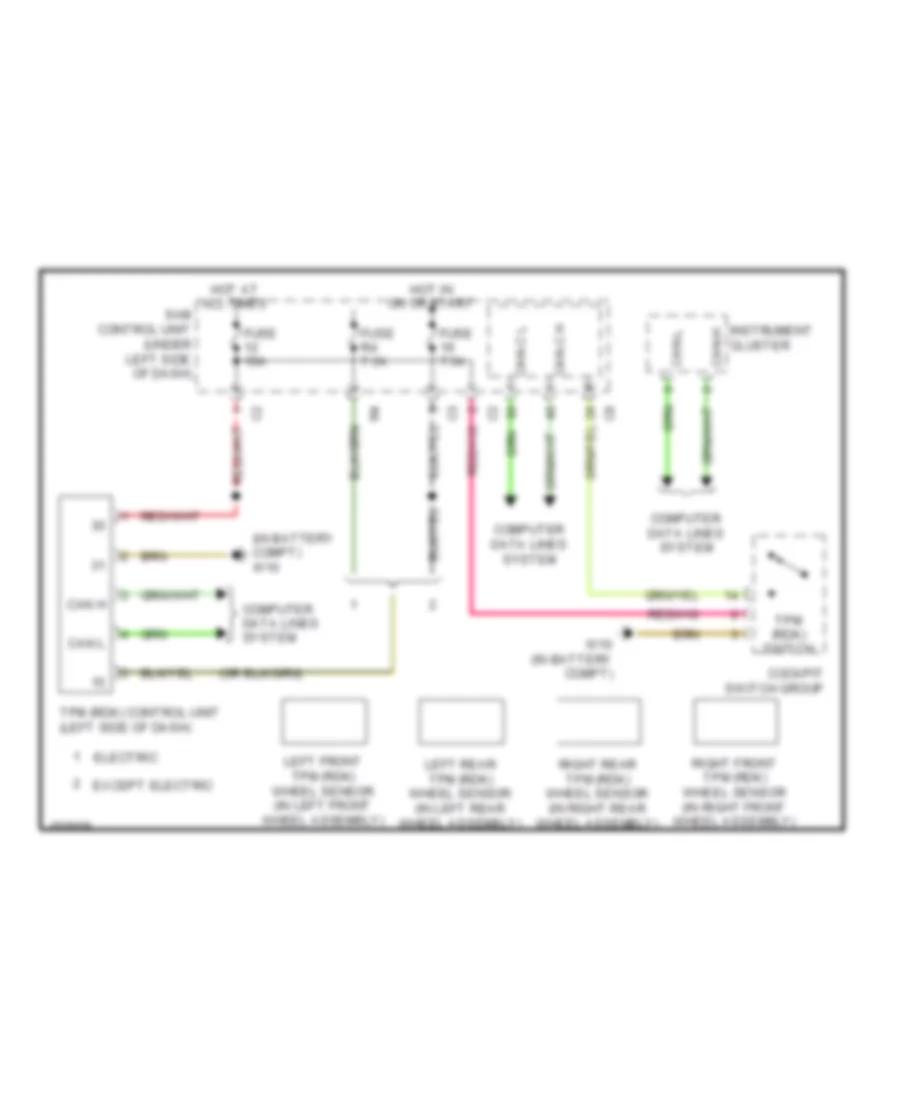
Tire Pressure Monitoring Wiring Diagram for Smart Fortwo Passion 2014
List of elements for Tire Pressure Monitoring Wiring Diagram for Smart Fortwo Passion 2014:
- (in battery compt) w10
- Can h
- Can l
- Can-c h
- Can-c l
- Can-h
- Can-l
- Cockpit switch group
- Computer data lines system
- Electric
- Except electric
- Fuse 10a
- Fuse 7.5a
- Fuse r4 7.5a
- Hot at all times
- Hot in on or start
- Instrument cluster
- Left front tpm (rdk) wheel sensor (in left front wheel assembly)
- Left rear tpm (rdk) wheel sensor (in left rear wheel assembly)
- Right front tpm (rdk) wheel sensor (in right front wheel assembly)
- Right rear tpm (rdk) wheel sensor (in right rear wheel assembly)
- Sam control unit (under left side of dash)
- Tpm (rdk) control unit (left side of dash)
- Tpm (rdk) switch
- W10 (in battery compt)
WIPER/WASHER
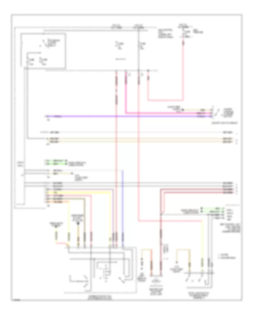
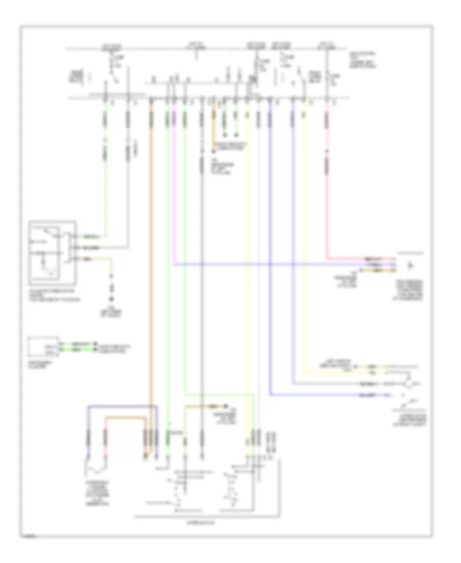
Wiper/Washer Wiring Diagram for Smart Fortwo Passion 2014
List of elements for Wiper/Washer Wiring Diagram for Smart Fortwo Passion 2014:
- (left side of service compt) w43
- (not used)
- 53l
- C10
- Can c h
- Can c l
- Can h
- Can l
- Computer data lines system
- Coupe
- Front wiper relay
- Fuse 10a
- Fuse 15a
- Fuse 25a
- Hot at all times
- Hot in on or start
- Instrument cluster
- Int 53b
- Lin 1
- Rain sensor/ light sensor (if equipped) (top center of windshield)
- Rear wiper relay
- Sam control unit (under left side of dash)
- Tailgate wiper motor (coupe) (top center of tailgate)
- W6 (left rear of trunk)
- W9 (near base of left "a" pillar)
- Windshield washer fluid pump (on washer fluid reservoir)
- Wiper motor (center rear of front compt)
- Wiper switch
- X18/19-c1

 Čeština
 Dansk
Dansk Deutsch
 Ελληνικά
 English
 English
 Español
 Suomi
Suomi Français
 Français
 עברית
עברית Hrvatski
 Magyar
 Italiano
 日本語
日本語 한국어
한국어 Nederlands
 Polski
 Português
 Português
 Română
 Русский
 Slovenčina
 Slovenščina
 Türkçe
 中文 (中国)