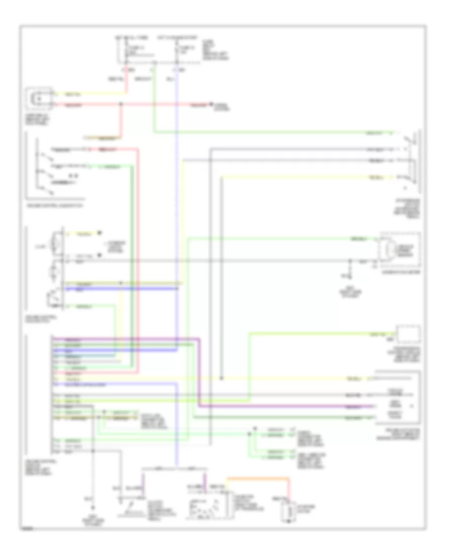
AIR CONDITIONING
A/C Wiring Diagram for Subaru Impreza Brighton 1997
 https://portal-diagnostov.com/license.html
Automotive Electricians Portal FZCO
Automotive Electricians Portal FZCO
https://portal-diagnostov.com/license.html
https://portal-diagnostov.com/license.html
Automotive Electricians Portal FZCO
Automotive Electricians Portal FZCO
List of elements for A/C Wiring Diagram for Subaru Impreza Brighton 1997:
- (left side of engine compartment)
- (right radiator support)
- (right side
- A/c relay holder
- A/c switch
- Acc
- Air conditioner fuse 10a
- Air conditioning cut relay (right side of firewall)
- Air conditioning relay (in a/c relay holder)
- Blower motor
- Blower motor relay (behind left side of dash)
- Blower motor resistor (behind right side of dash)
- Clutch
- Compressor
- Diode (a/c) (behind left side of dash)
- E11
- Engine control module (under passenger floorboard)
- Evaporation thermoswitch (behind right side of dash)
- F27
- Fan switch
- Fuse 10a
- Fuse 20 15a
- Fuse 20a
- Fuse 21 15a
- Fuse and relay box
- G109
- G201
- Hot at all times
- Hot in on or start
- I17
- I30
- Ignition switch
- Interior lights system
- Main fan motor
- Main fan relay
- Mode control panel
- Nca
- Of dash)
- Off
- Pressure switch
- Run
- Start
- Sub fan motor
- Sub-fan relay (in a/c relay holder)
- Thermal protector
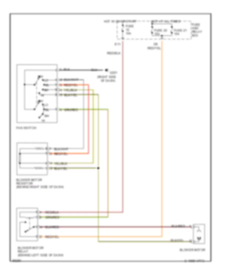
Heater Wiring Diagram for Subaru Impreza Brighton 1997
List of elements for Heater Wiring Diagram for Subaru Impreza Brighton 1997:
- (right side
- Blower motor
- Blower motor relay (behind left side of dash)
- Blower motor resistor (behind right side of dash)
- C 1995 vftc
- E11
- Fan switch
- Fuse 10a
- Fuse 20 15a
- Fuse 21 15a
- Fuse and relay box
- G201
- Hot at all times
- Hot in on or start
- Of dash)
- Off
ANTI-LOCK BRAKES
Anti-lock Brake Wiring Diagrams (1 of 2) for Subaru Impreza Brighton 1997
List of elements for Anti-lock Brake Wiring Diagrams (1 of 2) for Subaru Impreza Brighton 1997:
- Abs control module (left side of engine compartment)
- Abs diagnosis connector (behind left side of dash)
- B51
- B56
- Check connector (behind left side of dash)
- Data link connector (under left side of dash)
- F34
- F42
- F49
- Fuse & relay box (left side of dash)
- Fuse 12 20a
- Fuse 15 10a
- Fuse 18
- Fuse 19 20a
- G102 (left strut tower)
- Hot at all times
- Hot in run or start
- Left front wheel sensor
- Left rear wheel sensor
- Main fuse box (left side of engine compartment)
- Nca
- Obd ii service connector (below left side of dash)
- Pnk
- Red
- Right front wheel sensor
- Right rear wheel sensor
- Sbf-6 fuse 45a
- Shield joint connector (left side of engine compartment)
- Stoplight switch (top of brake pedal bracket)
- Transmission control module (behind left side of dash)
Anti-lock Brake Wiring Diagrams (2 of 2) for Subaru Impreza Brighton 1997
List of elements for Anti-lock Brake Wiring Diagrams (2 of 2) for Subaru Impreza Brighton 1997:
- Abs control module (left side of engine compartment)
- Abs g sensor (left rear of engine compartment)
- Abs hydraulic module (right front of engine compartment)
- Abs ind
- Abs pump motor
- Abs1
- Abs2
- F49
- G201 (right side of dash)
- I10
- I12
- Instrument cluster
- Left front solenoids
- Left rear solenoids
- Motor relay
- Nca
- Pnk
- Red
- Relay box (right front of engine compt)
- Right front solenoids
- Right rear solenoids
- Valve relay
COMPUTER DATA LINES
Computer Data Lines for Subaru Impreza Brighton 1997
List of elements for Computer Data Lines for Subaru Impreza Brighton 1997:
- (behind dash, right of steeering column)
- Abs check connector
- Abs control module
- Airbag control module
- Airbag ind
- B115
- B125
- B126
- B40
- B52
- B56
- B75
- B76
- B78
- B79
- B81
- B82
- B84
- B94
- C12
- C13
- Check connector (behind left side of dash)
- Combination meter
- Cruise control module (behind left side of dash)
- Data link connector (behind dash, near steering column)
- Diagnosis connector
- Diagnosis terminal
- E11
- Engine control module (behind right side of dash)
- F37
- F49
- Fuse & relay box (behind left side of dash)
- Fuse 15 10a
- Fuse sbf2 30a
- G201 (right side of dash)
- Hot at all times
- Hot in on or start
- I13
- Main fuse box (left side of engine compt)
- Main relay (behind left side of dash)
- Nca
- Neutral position switch (m/t) (left side of transmission)
- Obd ii service connector (below left side of dash)
- Test mode connector (behind dash, right of steering column)
- Test mode connector (right kick panel)
- Transmission control module (behind left side of dash)
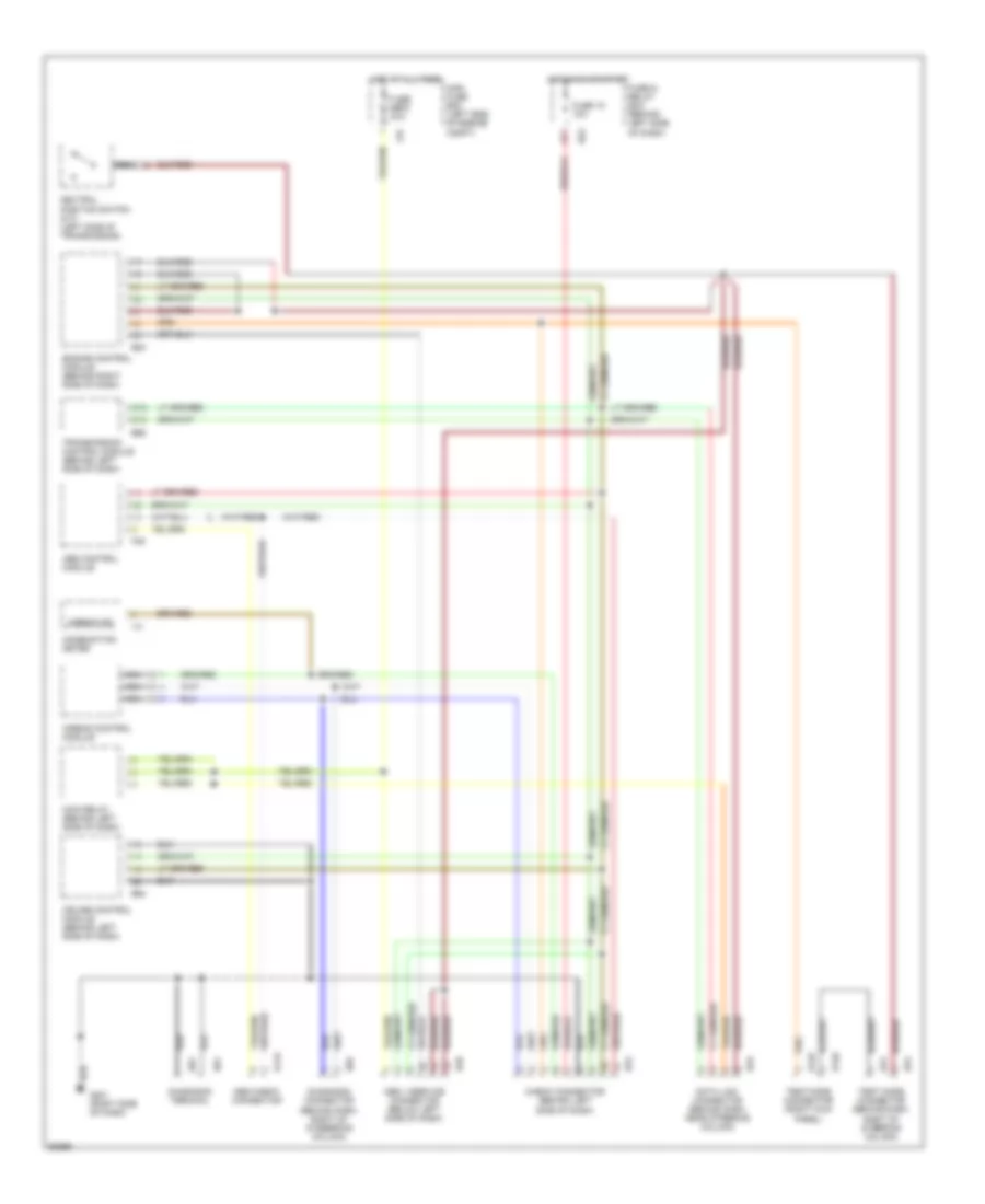
COOLING FAN
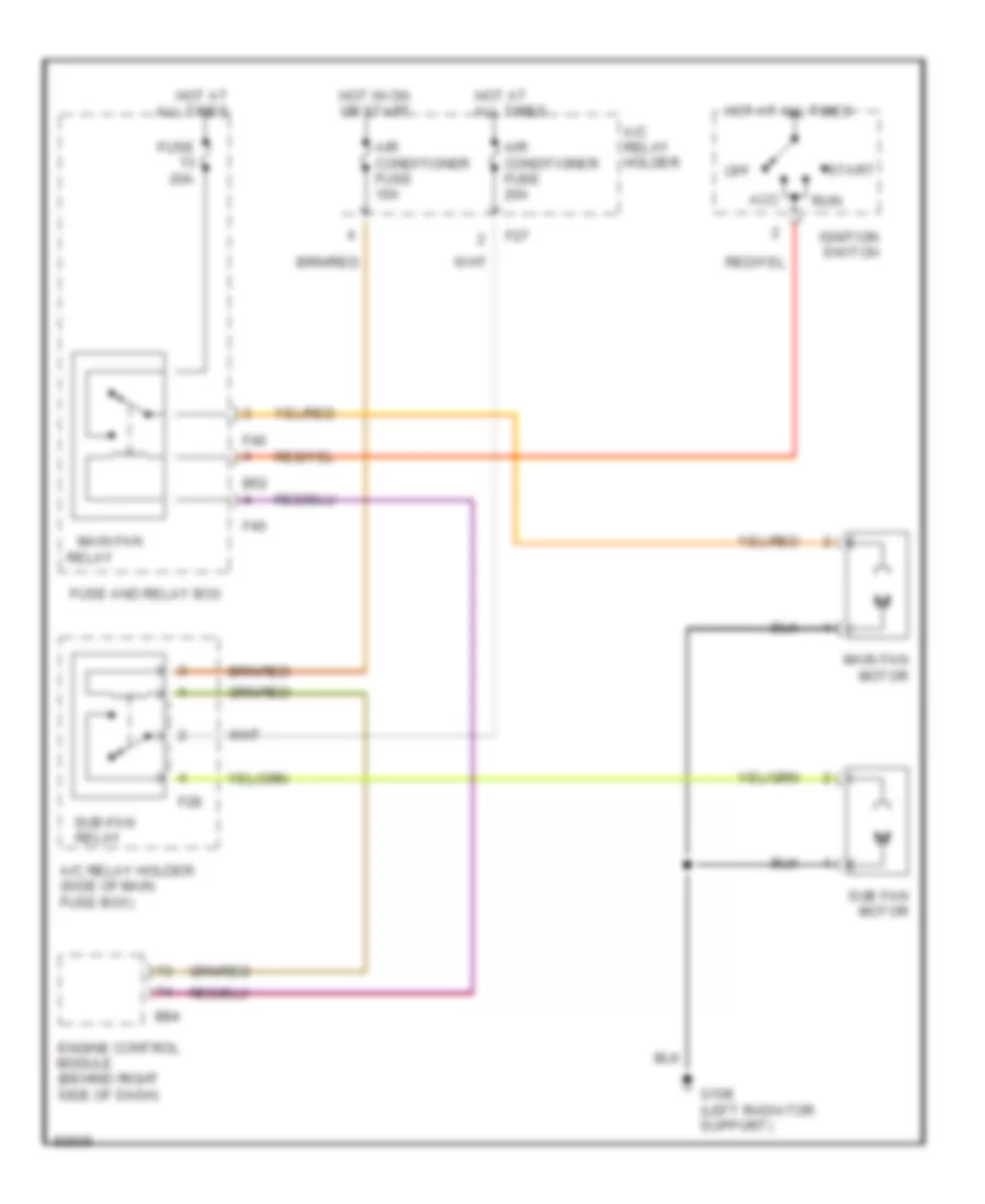
Cooling Fan Wiring Diagram, with A/C for Subaru Impreza Brighton 1997
List of elements for Cooling Fan Wiring Diagram, with A/C for Subaru Impreza Brighton 1997:
- A/c relay holder
- A/c relay holder (side of main fuse box)
- Acc
- Air conditioner fuse 10a
- Air conditioner fuse 20a
- B52
- B84
- Engine control module (behind right side of dash)
- F27
- F28
- F40
- Fuse 20a
- Fuse and relay box
- G108 (left radiator support)
- Hot at all times
- Hot in on or start
- Ignition switch
- Main fan
- Main fan motor
- Off
- Relay
- Relay
- Run
- Start
- Sub fan motor
- Sub-fan
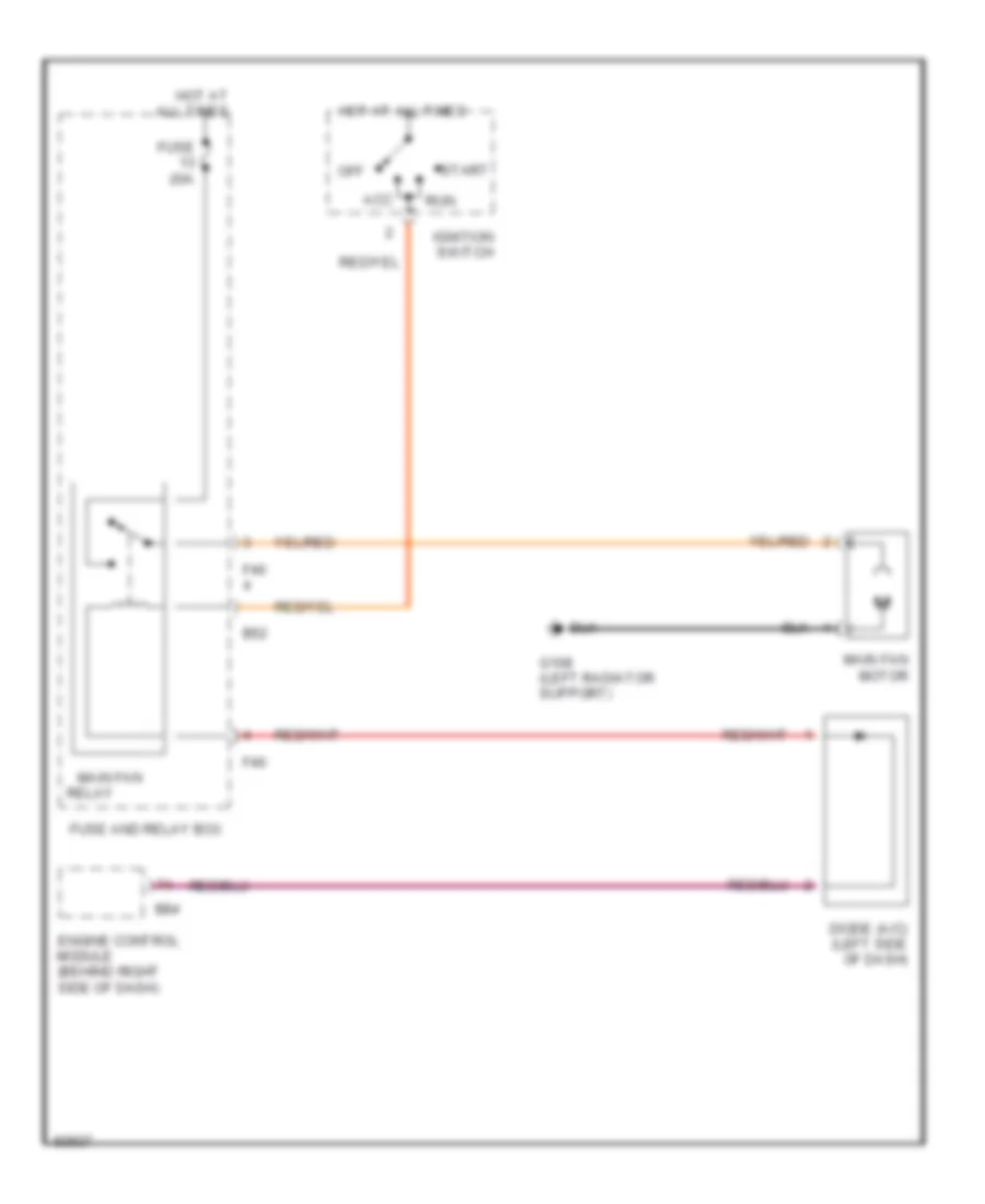
Cooling Fan Wiring Diagram, without A/C for Subaru Impreza Brighton 1997
List of elements for Cooling Fan Wiring Diagram, without A/C for Subaru Impreza Brighton 1997:
- Acc
- B52
- B84
- Diode (a/c) (left side of dash)
- Engine control module (behind right side of dash)
- F40
- Fuse 20a
- Fuse and relay box
- G108 (left radiator support)
- Hot at all times
- Ignition switch
- Main fan
- Main fan motor
- Off
- Relay
- Run
- Start
CRUISE CONTROL
Cruise Control Wiring Diagram for Subaru Impreza Brighton 1997
List of elements for Cruise Control Wiring Diagram for Subaru Impreza Brighton 1997:
- A/t
- B51
- B52
- B56
- Cancel
- Check connector (behind left side of dash)
- Clutch switch (on bracket above clutch pedal)
- Combination meter
- Cruise actuator (right rear of engine compartment)
- Cruise control main switch
- Cruise control module (behind left side of dash)
- Cruise control sub switch
- Data link connector (below left side of dash)
- Fuse 12 20a
- Fuse 18 10a
- Fuse/ relay box (behind left side of dash)
- G201 (right side of dash)
- Horn relay (behind left kick panel)
- Horns system
- Hot at all times
- Hot in on and start
- I12
- Illum
- Inhibitor switch (right side of transaxle)
- Interior lights system
- M/t
- Obd ii service connector (below left side of dash)
- Off
- Resume
- Safety valve
- Set
- Starter motor
- Stop/brake switch (on bracket above brake pedal)
- Transmission control module (behind left side of dash)
- Vacuum valve
- Vehicle speed sensor
- Vent valve
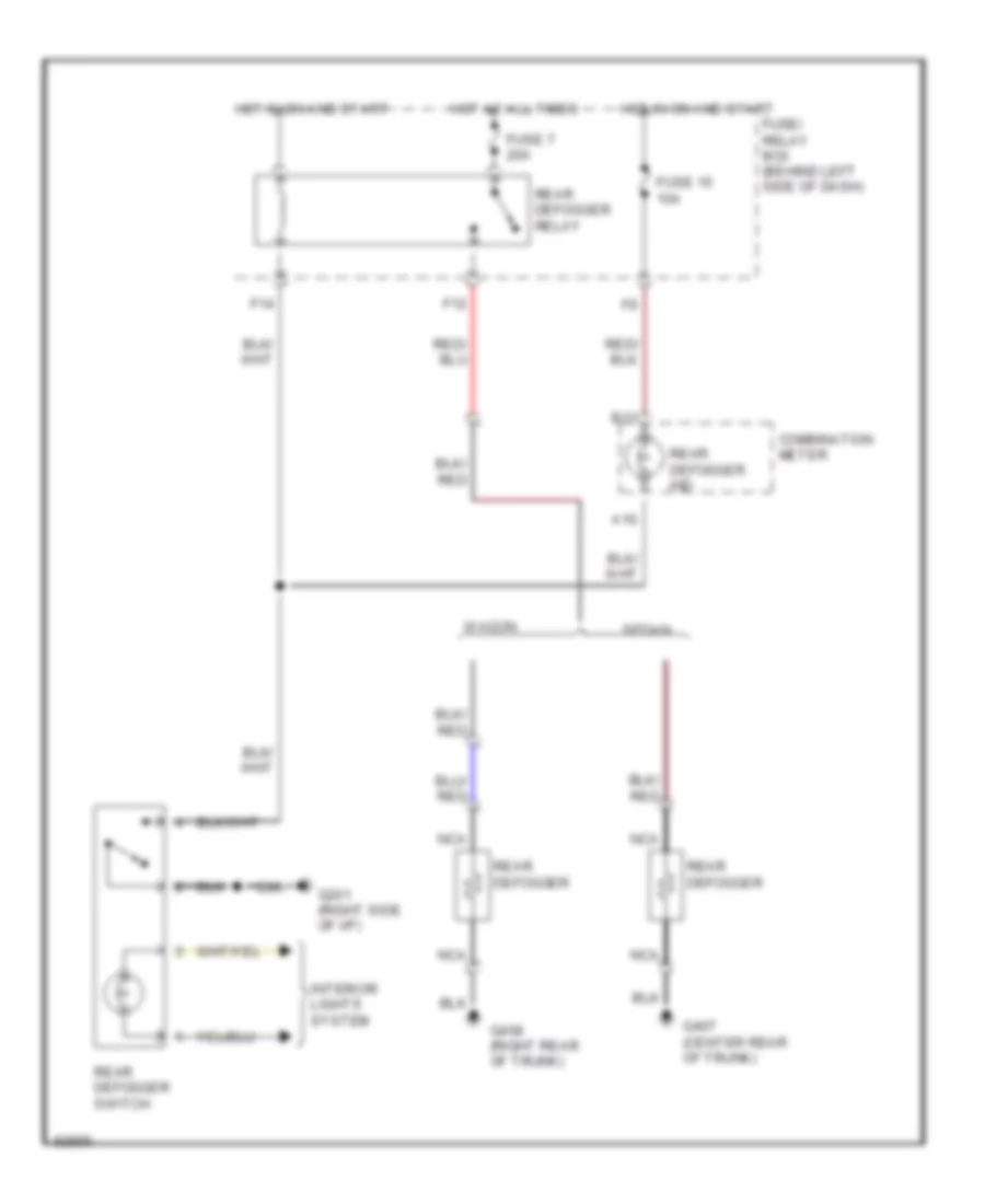
DEFOGGERS
Defogger Wiring Diagram for Subaru Impreza Brighton 1997
List of elements for Defogger Wiring Diagram for Subaru Impreza Brighton 1997:
- A10
- B13
- Combination meter
- F12
- F14
- Fuse 15 10a
- Fuse 7 20a
- Fuse/ relay box (behind left side of dash)
- G201 (right side of i/p)
- G407 (center rear of trunk)
- G408 (right rear of trunk)
- Hot at all times
- Hot in on and start
- Interior lights system
- Nca
- Rear defogger
- Rear defogger ind
- Rear defogger relay
- Rear defogger switch
- Sedan
- Wagon
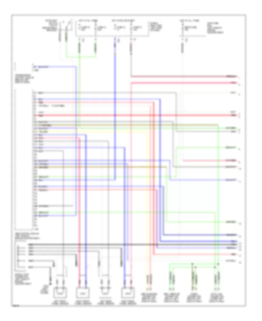
ENGINE PERFORMANCE
1.8L
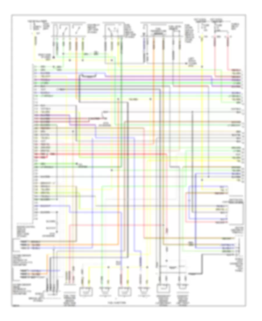
1.8L, Engine Performance Wiring Diagrams (1 of 2) for Subaru Impreza Brighton 1997
List of elements for 1.8L, Engine Performance Wiring Diagrams (1 of 2) for Subaru Impreza Brighton 1997:
- (left shock tower) g102
- (on engine)
- (right side of dash) g201
- A/c system
- B52
- Camshaft position sensor (left front of eng)
- Crankshaft position sensor (lower front of eng)
- Engine control module (behind right side of dash)
- F37
- F40
- Fuel gauge module (below rear of vehicle, in fuel tank)
- Fuel injectors
- Fuel level sensor
- Fuel pump relay (behind left side of dash)
- Fuel tank pressure sensor (right side of trunk)
- Fuel temperature sensor
- Fuse & relay box
- Fuse 10a
- Fuse 15a
- G133
- G133 (on engine)
- Hot at all times
- Hot in run
- Ignition coil (top front of eng)
- Ignitor (center of firewall)
- Main fuse box
- Main relay (behind left side of dash)
- Nca
- Or start
- Oxygen sensor (front) (on front of front catalytic converter)
- Oxygen sensor (rear) (on rear of rear catalytic converter)
- Red
- Sbf-2 30a
- Shield j/c (brhind left of dash)
- Shield joint connector (right kick panel)
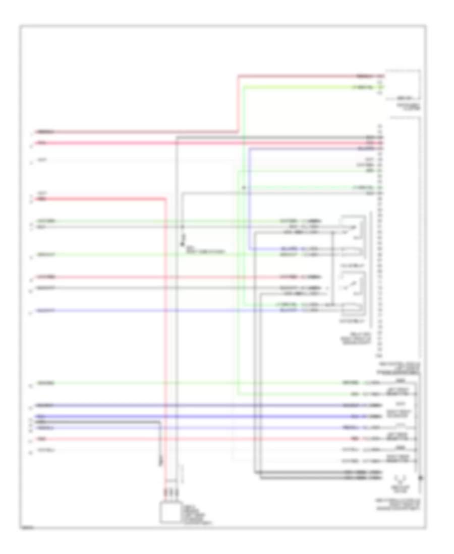
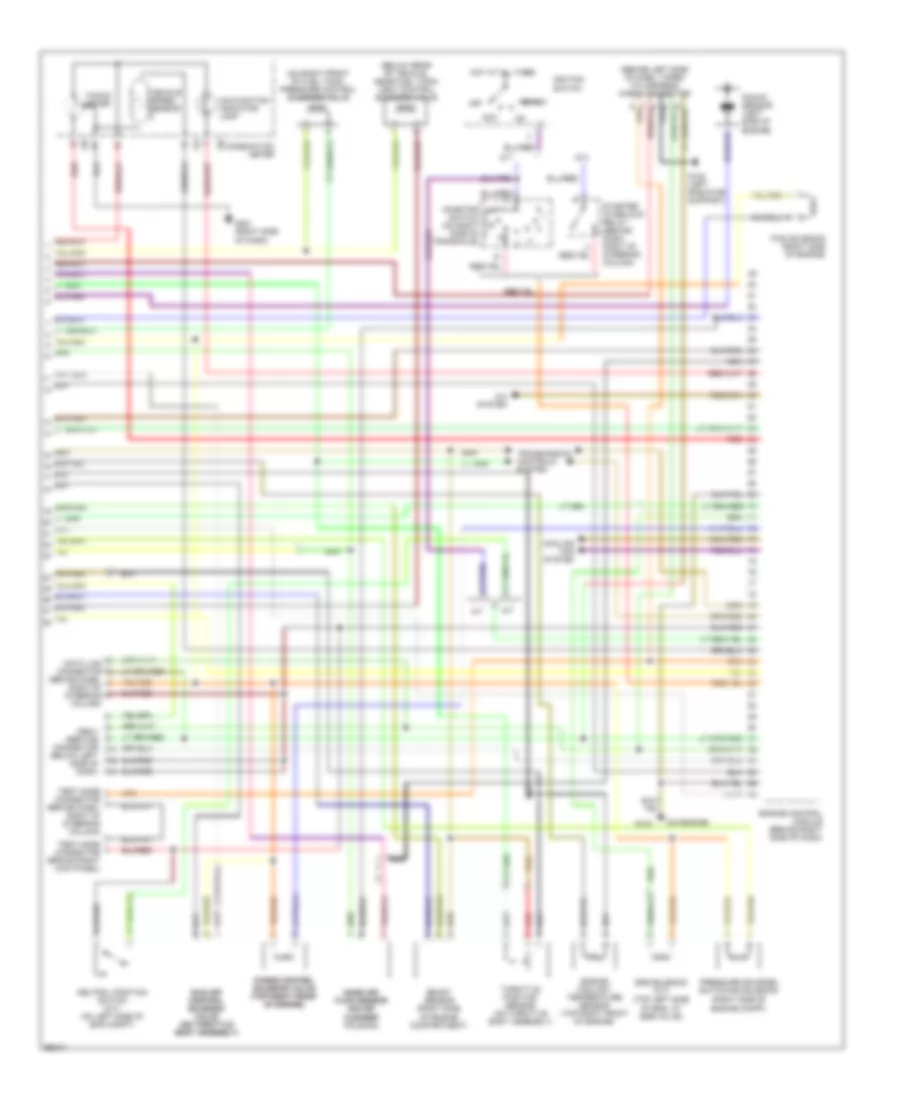
1.8L, Engine Performance Wiring Diagrams (2 of 2) for Subaru Impreza Brighton 1997
List of elements for 1.8L, Engine Performance Wiring Diagrams (2 of 2) for Subaru Impreza Brighton 1997:
- (behind dash, right of steering column)
- (behind left side of dash, taped to harness) check connector
- (below rear of vehicle, near fuel tank) vent control solenoid valve
- (on air (on air cleaner cleaner housing)
- (on engine)
- (on right front of fuel tank) pressure control solenoid valve
- (right side of engine compartment)
- (right side of engine compt)
- (top left side of eng, at egr valve)
- A/c system
- A/t
- Acc
- Boost sensor
- Combination meter
- Cooling fan system
- Data link connector
- Egr solenoid (a/t)
- Engine control module (behind right side of dash)
- Engine coolant temperature sensor (top right front of engine)
- Ficd solenoid (right side of engine)
- G108 (left radiator support)
- G133
- G201 (right side of dash)
- Hot at all times
- I10
- I12
- Idle air idle air control control solenoid solenoid valve valve (on throttle (on throttle body assembly) body assembly)
- Ignition switch
- Inhibitor switch (on right side of transaxle)
- Knock sensor (left side of engine)
- M/t
- Malfunction indicator lamp
- Mass air mass air flow sensor flow sensor
- Nca
- Neutral position switch (m/t) (on left side of eng compt)
- Obd-ii service connector (below left side of dash)
- Off
- Pressure sources switching solenoid
- Purge control purge control solenoid valve solenoid valve (top right front (top right front of engine) of engine)
- Red
- Start
- Starter interlock relay (behind dash, right of steering column)
- Tacho- meter
- Test mode connector (behind dash, right of steering column)
- Test mode connector (brhind right kick panel)
- Throttle position sensor (on throttle body assembly)
- Transmission controls system
- Vehicle speed sensor
2.2L
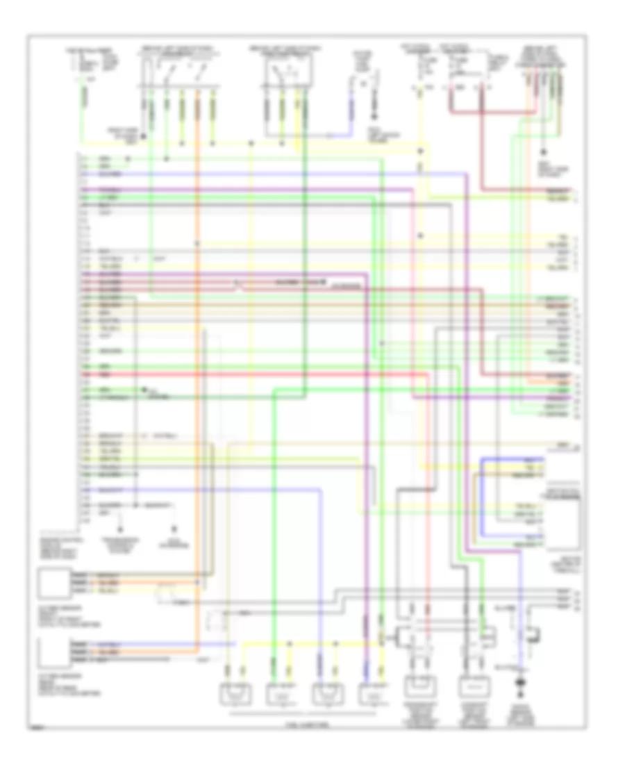
2.2L, Engine Performance Wiring Diagrams (1 of 2) for Subaru Impreza Brighton 1997
List of elements for 2.2L, Engine Performance Wiring Diagrams (1 of 2) for Subaru Impreza Brighton 1997:
- (behind left side of dash) fuel pump relay
- (behind left side of dash) main relay
- (behind left side of dash, taped to harn) check connector
- (in fuel tank) fuel pump
- (on engine)
- (right side of dash) g201
- A/c system
- B52
- Camshaft position sensor (left front of engine)
- Crankshaft position sensor (lower front of engine)
- Engine control module (behind right side of dash)
- F37
- F40
- Fuel injectors
- Fuse & relay box
- Fuse 10a
- Fuse 15a
- G102 (left shock tower)
- G133
- G133 (on engine)
- G201 (right side of dash)
- Hot at all times
- Hot in run
- Ignition coil (top of engine)
- Ignitor (center of firewall)
- Knock sensor (left side of engine)
- Main fuse box
- Nca
- Or start
- Oxygen sensor (front) (front of front catalytic converter)
- Oxygen sensor (rear) (rear of rear catalytic converter)
- Red
- Sbf-2 30a
- Transmission controls system
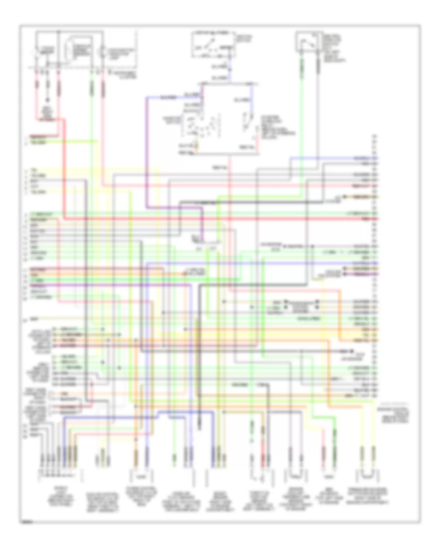
2.2L, Engine Performance Wiring Diagrams (2 of 2) for Subaru Impreza Brighton 1997
List of elements for 2.2L, Engine Performance Wiring Diagrams (2 of 2) for Subaru Impreza Brighton 1997:
- (on engine)
- (part of air intake assembly, neat to air cleaner box)
- (right side of engine compartment)
- (top left side of engine)
- A/c system
- A/t
- Acc
- Boost sensor
- Cooling fan system
- Data link connector (on dash,
- Egr solenoid
- Engine control module (behind right (side of dash)
- Engine coolant temperature sensor (top right front of engine)
- G133
- G201 (right side of dash)
- Hot at all times
- I10
- I12
- Idle air control solenoid valve (on top of eng, near throttle body assembly)
- Ignition switch
- Inhibitor switch
- Instrument cluster
- Left of steering column)
- M/t
- Malfunction indicator lamp
- Mass air flow sensor
- Nca
- Neutral position switch (m/t) (on left side of eng compt)
- Obd-ii service connector (left side of dash)
- Off
- Pressure sources switching solenoid
- Purge control solenoid valve (on top right front of eng)
- Red
- Shield joint connector (behind right kick panel)
- Start
- Starter interlock relay (behind dash, left of steering column)
- Tacho- meter
- Test mode connector (left side of dash)
- Test mode connector (right of dash)
- Throttle position sensor (on throttle body assembly)
- Transmission control system
- Vehicle speed sensor
EXTERIOR LIGHTS
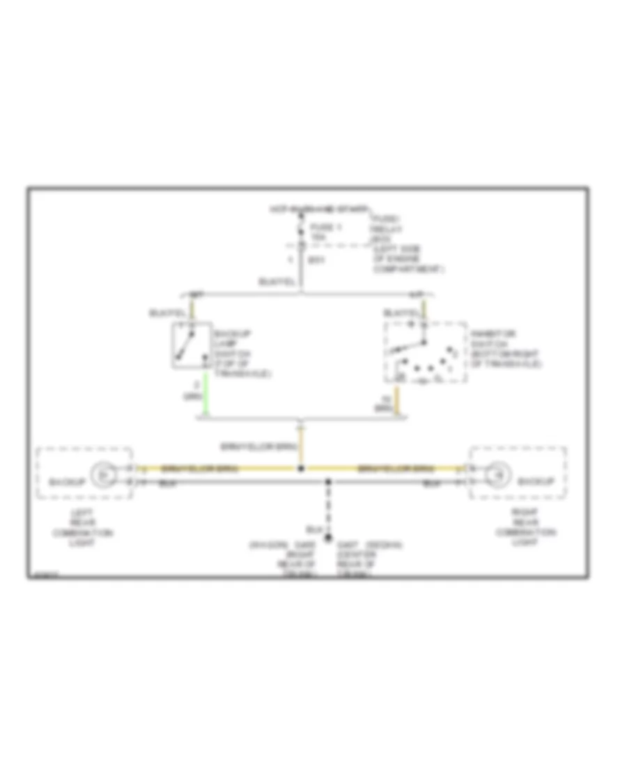
Back-up Lamps Wiring Diagram for Subaru Impreza Brighton 1997
List of elements for Back-up Lamps Wiring Diagram for Subaru Impreza Brighton 1997:
- (sedan)
- (wagon)
- A/t
- B51
- Backup
- Backup lamp switch (top of transaxle)
- Fuse 1 15a
- Fuse/ relay box (left side of engine compartment)
- G405 (right rear of trunk)
- G407 (center rear of trunk)
- Hot in on and start
- Inhibitor switch (bottom right of transaxle)
- Left rear combination light
- M/t
- Right rear combination light
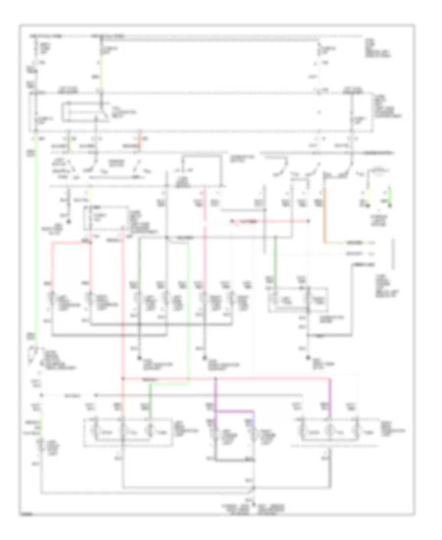
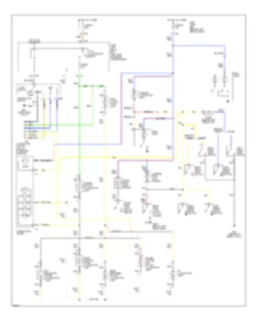
Exterior Lamps Wiring Diagram for Subaru Impreza Brighton 1997
List of elements for Exterior Lamps Wiring Diagram for Subaru Impreza Brighton 1997:
- (or
- (right side
- (sedan)
- (wagon)
- A11
- B15
- B35
- B51
- B52
- B57
- Combination meter
- Combination switch
- F35
- F36
- F40
- F42
- Fuse 1 15a
- Fuse 12 20a
- Fuse 22 15a
- Fuse 23 20a
- Fuse 5 10a
- Fuse/ relay box (left side of engine compartment)
- G108 (left radiator support)
- G109 (right radiator support)
- G201
- G201 (right side of i/p)
- G405 (right rear of trunk)
- G407 (center rear of trunk)
- Hazard switch
- Head
- High mount stop light
- Hot at all times
- Hot in on and start
- Interior lights system
- Left front clearance light
- Left front turn light
- Left license plate light
- Left rear combination lamp
- Left side turn light
- Left turn
- Light switch
- Main fuse box (behind left side of dash)
- Of i/p)
- Off
- Park
- Parking switch
- Red
- Right front clearance light
- Right front turn light
- Right license plate light
- Right rear combination lamp
- Right side turn light
- Right turn
- Sbf-3 fuse 45a
- Stop
- Stop/ brake switch (on brake pedal bracket)
- Tail
- Tail/ illumination relay
- Turn
- Turn signal switch
- Turn signal/ hazard unit (below left side of i/p)
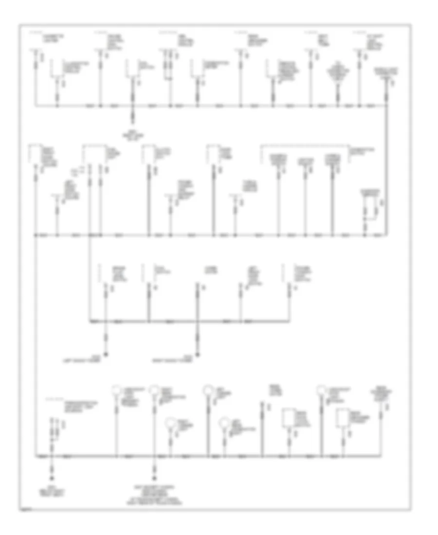
GROUND DISTRIBUTION
Ground Distribution Wiring Diagram (1 of 2) for Subaru Impreza Brighton 1997
List of elements for Ground Distribution Wiring Diagram (1 of 2) for Subaru Impreza Brighton 1997:
- 1.8l
- 2.2l
- A/t shift lock control module
- Abs control module
- B106
- B119
- B16
- B177
- B32
- B42
- B43
- B44
- B57
- B69
- B70
- B71
- B81
- B92
- Brake fluid level switch
- Cigarette lighter
- Clutch switch (m/t)
- Combination meter
- Combination switch
- Cruise control main switch
- D39
- D43
- D46
- D48
- Diagnosis terminal
- Dimmer & passing switch
- Door lock timer
- F48
- F49
- Fan switch
- Fuel gauge unit
- Fwd switch
- G102 (left shock tower)
- G103 (right shock tower)
- G201 (right side of i/p)
- G301 (below right front seat)
- G407 (except wagon) g405 (wagon) (center rear of trunk-except wagon, right rear of trunk-wagon)
- High-mount stop light (except wagon)
- High-mount stop light (wagon)
- I12
- I15
- I18
- I19
- Illumination control module
- Left front door lock switch
- Left front door switch (coupe)
- Left license light
- Left rear combination light
- Lighting switch
- Parking position and shift lock solenoid
- Power window and sunroof relay
- Power window main switch
- R12
- R19
- R26
- R28
- R33
- R58
- R76
- R77
- Rear defogger (wagon)
- Rear defogger switch
- Rear gate latch switch
- Rear wiper motor
- Remote control rearview mirror switch
- Right front door switch (coupe)
- Right license light
- Right rear combination light
- Seat belt timer
- Shield joint connector (a.b.s.)
- To check connector (diagram 2 of 2)
- Turn & hazard module
- Wiper & washer switch
- Wiper motor
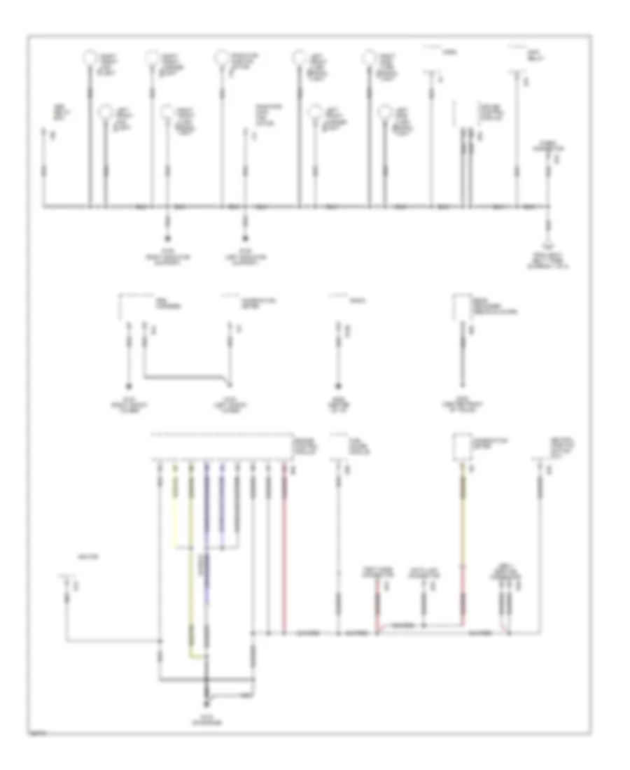
Ground Distribution Wiring Diagram (2 of 2) for Subaru Impreza Brighton 1997
List of elements for Ground Distribution Wiring Diagram (2 of 2) for Subaru Impreza Brighton 1997:
- Abs relay box
- B120
- B13
- B25
- B31
- B40
- B47
- B76
- B78
- B79
- B84
- B94
- Check connector
- Combination meter
- Cruise control module
- Data link connector
- Engine control module
- F16
- F17
- F19
- F21
- F50
- F51
- F52
- F53
- F54
- From seat belt timer (diagram 1 of 2)
- Fuel gauge module
- G102 (left shock tower)
- G103 (right shock tower)
- G108 (left radiator support)
- G109 (right radiator support)
- G133 (on engine)
- G206 (center of i/p)
- G408 (center front of trunk)
- Horn
- I10
- I13
- Ignitor
- Left front fog light
- Left front marker light
- Left front turn signal light
- Left side turn signal light
- Main relay
- Nca
- Neutral position switch (m/t)
- Obd ii service connector
- R58
- R65
- Radiator main fan motor
- Radiator sub fan motor
- Radio
- Rear defogger (sedan & coupe)
- Right front fog light
- Right front marker light
- Right front turn signal light
- Right side turn signal light
- Srs harness
- Test mode connector
HEADLIGHTS
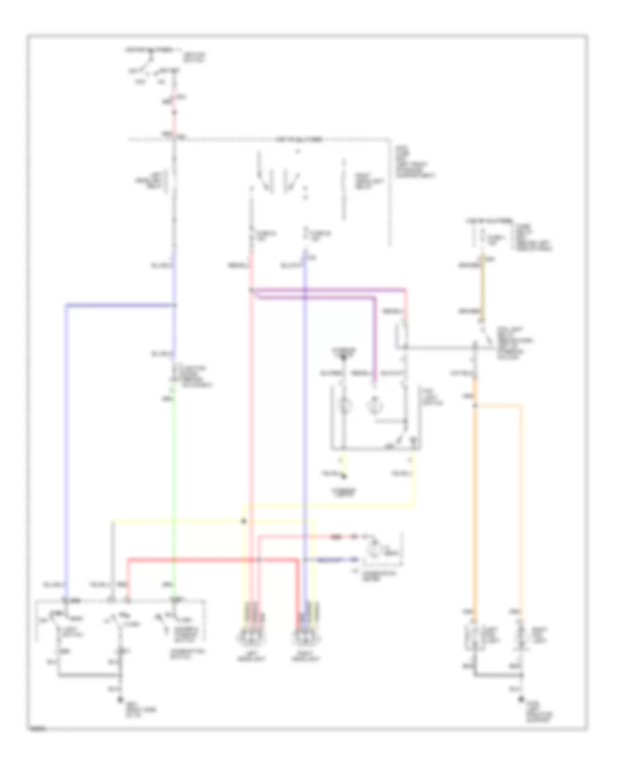
Headlight Wiring Diagram for Subaru Impreza Brighton 1997
List of elements for Headlight Wiring Diagram for Subaru Impreza Brighton 1997:
- Acc
- B48
- B69
- B71
- B72 red
- Combination meter
- Combination switch
- Dimmer & passing switch
- Flash
- Fog light relay (behind dash, left of steering column)
- Fog light switch
- Fuse 24 15a
- Fuse 26 15a
- Fuse 4 15a
- Fuse/ relay box (behind left side of dash)
- G109 (left radiator support
- G201 (right side of i/p)
- Head
- Hi beam
- Hot at all times
- I12
- Ignition switch
- Interior lights
- Left fog light
- Left headlight
- Left headlight relay
- Light switch
- Lighting diode (behind glove box)
- Main fuse box (left front of engine compartment)
- Off
- Park
- Red
- Red f39
- Right fog light
- Right headlight
- Right headlight relay
- Start
HORN
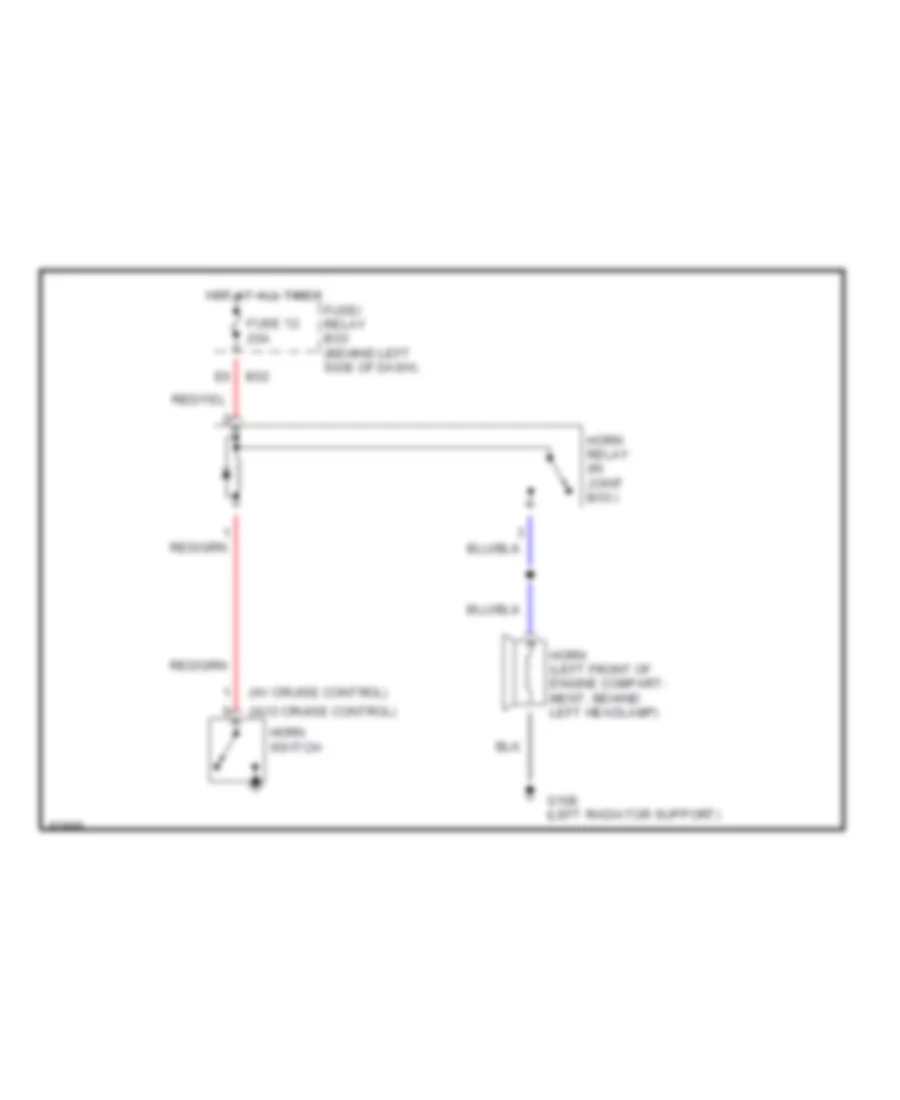
Horn Wiring Diagram for Subaru Impreza Brighton 1997
List of elements for Horn Wiring Diagram for Subaru Impreza Brighton 1997:
- (w/ cruise control)
- (w/o cruise control)
- B52
- Fuse 12 20a
- Fuse/ relay box (behind left side of dash)
- G108 (left radiator support)
- Horn (left front of engine compart- ment, behind left headlamp)
- Horn relay (in joint box)
- Horn switch
- Hot at all times
INSTRUMENT CLUSTER
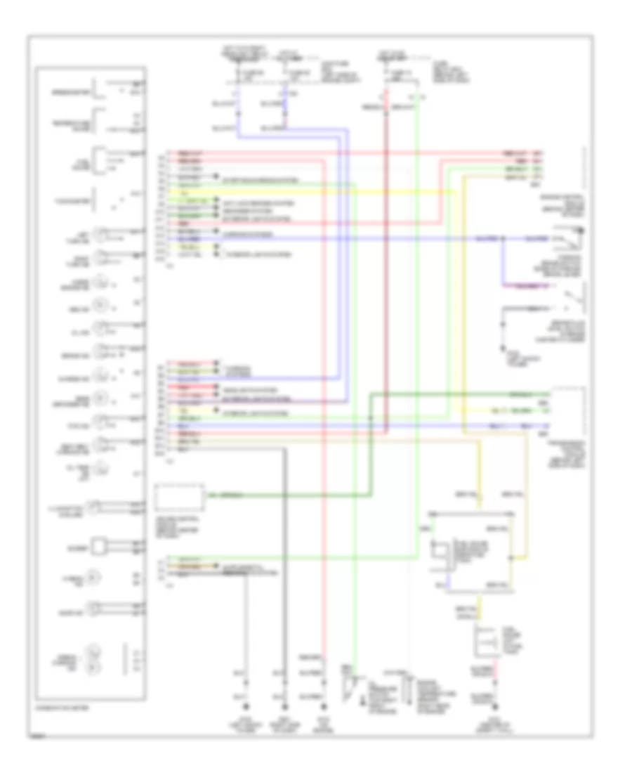
Instrument Cluster Wiring Diagram for Subaru Impreza Brighton 1997
List of elements for Instrument Cluster Wiring Diagram for Subaru Impreza Brighton 1997:
- 1.8l
- 2.2l
- A10
- A11
- A12
- A13
- A14
- A15
- A16
- Abs ind
- Airbag warning ind
- Anti-lock brakes system
- B12
- B13
- B14
- B15
- B55
- B56
- B84
- Brake fluid level switch (in brake master cylinder)
- Brake ind
- Buzzer
- Charge ind
- Check engine ind
- Combination meter
- Cruise control module (behind center of dash)
- Defogger system
- Door ind
- Engine control module (behind center of dash)
- Engine coolant temperature sensor (right rear of engine)
- Exterior lights system
- F35
- Fuel gauge
- Fuel gauge sub module (near fuel tank)
- Fuel gauge unit (in fuel tank)
- Fuse 15 15a
- Fuse 25 10a
- Fuse 26 15a
- Fuse/ relay box (behind left side of dash)
- Fwd ind
- G102 (left shock tower)
- G121 (center of safety wall)
- G133 (on engine)
- G201 (right side of dash)
- Headlights system
- Hi beam ind
- Hot at all times
- Hot in on and start
- Hot with right headlight relay energized
- I10
- I12
- I13
- Illumination (5 bulbs)
- Interior lights system
- Left turn ind
- Main fuse box (left side of engine compt)
- Oil ind
- Oil pressure switch (top right front of engine)
- Oil temp ind (a/t)
- Parking brake switch (base of parking brake lever)
- Rear defogger ind
- Red
- Right turn ind
- Seat belt warning ind
- Speedometer
- Starting/charging system
- Tachometer
- Temperature gauge
- Transmission control module (behind left side of dash)
- Warning systems
INTERIOR LIGHTS
Interior Light Wiring Diagram for Subaru Impreza Brighton 1997
List of elements for Interior Light Wiring Diagram for Subaru Impreza Brighton 1997:
- A/t selector lever illumination light
- A15
- A16
- B69
- Cd illumination light
- Combination meter
- Combination switch
- Coupe
- Cruise control main switch illumination light
- D10
- Diode (behind left side of i/p)
- Door
- F35
- F40
- Fuse 23 20a
- Fuse 25 10a
- Fuse 9 10a
- Fuse and relay box (left side of engine compartment)
- Fuse box illumination light
- G121 (center of safety wall)
- G201 (right side of i/p)
- G300 (below left front seat)
- Hazard switch illumination light
- Head
- Hot at all times
- Hot in on and start
- I10
- I12
- I20
- Illumination control module (in center console)
- Left front door switch
- Left rear door switch
- Light switch
- Luggage room light (wagon)
- Main fuse box (behind left side of dash)
- Mode control panel illumination light
- Nca
- Off
- Park
- Radio illumin- ation light
- Rear defogger switch illumination light
- Rear gate latch switch (wagon)
- Right front door switch
- Right rear door switch
- Room light
- Sedan & wagon
- Spot light
- Tail/ illumination relay
- Trunk room light (sedan)
- Trunk room light switch (sedan)
POWER DISTRIBUTION
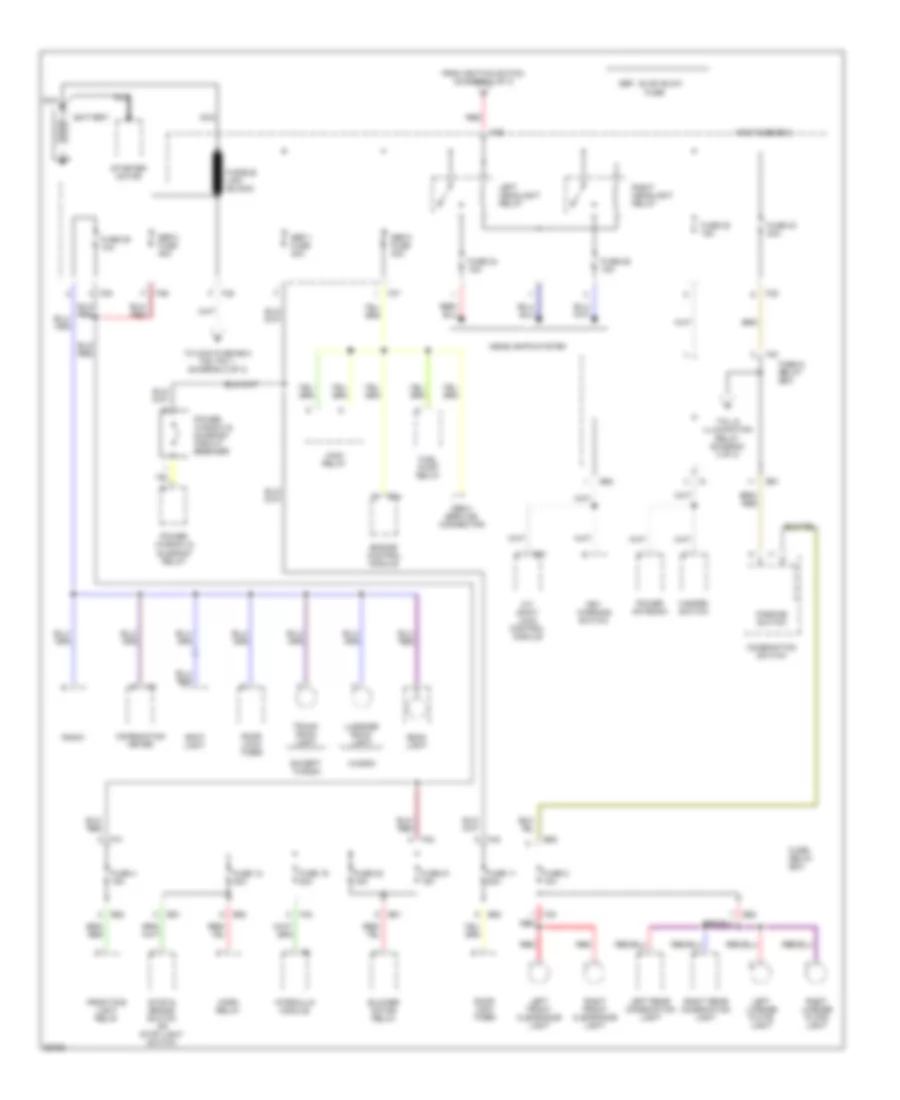
Power Distribution Wiring Diagram (1 of 3) for Subaru Impreza Brighton 1997
List of elements for Power Distribution Wiring Diagram (1 of 3) for Subaru Impreza Brighton 1997:
- A/t shift lock control module
- B51
- B52
- B57
- B84
- Battery
- Blower motor relay
- Combination meter
- Combination switch
- Door lock timer
- Engine control module
- Except wagon
- F35
- F36
- F37
- F38
- F39
- F40
- F41
- F42
- From ignition switch (diagram 2 of 3)
- Front fog light relay
- Fuel pump relay
- Fuse
- Fuse & relay box
- Fuse 11 20a
- Fuse 12 20a
- Fuse 19 20a
- Fuse 20 15a
- Fuse 21 15a
- Fuse 22 15a
- Fuse 23 20a
- Fuse 24 15a
- Fuse 25 10a
- Fuse 26 15a
- Fuse 4 15a
- Fuse 5 10a
- Fuse/ relay box
- Fusible link (black)
- Hazard switch
- Headlights system
- Horn relay
- Hydraulic module
- I12
- Key warning switch
- Left front clearance light
- Left headlight relay
- Left license plate light
- Left rear combination light
- Luggage room light
- Main fuse box
- Main relay
- Nca
- Obd-ii service connector
- Parking switch
- Power antenna
- Power window & sunroof circuit breaker
- Power window & sunroof relay
- Radio
- Red
- Right front clearance light
- Right headlight relay
- Right license plate light
- Right rear combination light
- Room light
- Sbf-1 fuse 30a
- Sbf-2 fuse 30a
- Sbf-3 fuse 45a
- Sbf: slow blow
- Spot light
- Starter motor
- Stop & brake switch or stop light switch
- Tail & illumination relay (diagram 3 of 3)
- To main fuse box f38, pin 1 (diagram 2 of 3)
- Trunk room light
- Wagon
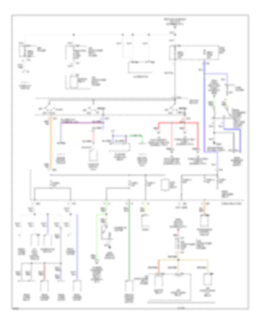
Power Distribution Wiring Diagram (2 of 3) for Subaru Impreza Brighton 1997
List of elements for Power Distribution Wiring Diagram (2 of 3) for Subaru Impreza Brighton 1997:
- (not used)
- 20a
- A/t
- A/t shift lock control module
- Acc
- Air conditioner fuse 10a
- Air conditioner relay holder
- Air conditioning cut relay
- Air conditioning relay
- Alternator
- B26
- B51
- B52
- B56
- B57
- B72
- B84
- Center front of pass. compt.)
- Cigarette lighter
- Combination switch
- Engine control module
- F25
- F26
- F27
- F28
- F31
- F34
- F35
- F36
- F38
- F40
- From fuse & relay box fuse 3 (diagram 2 of 3)
- From ignition switch (diagram 2 of 3)
- From main fuse box f38, pin 2 (diagram 1 of 3)
- Front washer motor
- Front wiper motor
- Fuse & relay box
- Fuse 13 20a
- Fuse 14 10a
- Fuse 17 15a
- Fuse 2 20a
- Fuse 3 15a
- Fuse 7 20a
- Fuse holder
- G206
- G206 (behind console)
- Hydraulic module
- Ignition switch
- Inhibitor switch (2.2l)
- M/t
- Main fan relay
- Main fuse box
- Neutral position switch (2.2l)
- Off
- Radiator fan fuse 20a
- Radio
- Rear defogger relay
- Rear washer motor
- Rear wiper motor
- Rear wiper relay
- Red
- Remote control mirror switch
- Sbf holder
- Sbf-4 fuse 45a
- Sbf-5 fuse 45a
- Sbf-6 fuse 45a
- Start
- Starter interlock relay
- Sub fan relay
- Sub-fan relay
- To fuse & relay box fuse 1 (diagram 3 of 3)
- To fuse & relay box fuse 18 (diagram 3 of 3)
- To main fuse box a/c fuse (10a) (diagram 2 of 3)
- To main fuse box headlight relays (diagram 1 of 3)
- Transmission control module
- W/ a/c
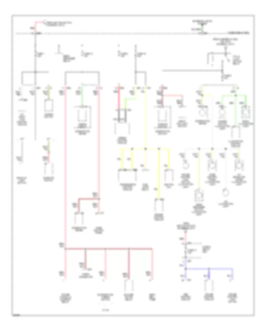
Power Distribution Wiring Diagram (3 of 3) for Subaru Impreza Brighton 1997
List of elements for Power Distribution Wiring Diagram (3 of 3) for Subaru Impreza Brighton 1997:
- A/t
- A/t selector lever illumination light
- A/t shift lock control module
- Abs control module
- Airbag circuit
- Airbag control module
- B31
- B51
- B52
- B54
- B55
- B57
- B79
- B84
- Back-up light switch
- Blower motor relay
- Cd illumination light
- Check connector
- Combination meter
- Combination switch
- Cruise control main switch
- Cruise control main switch illumination light
- Cruise control module
- Engine control module
- Evaporation thermo switch
- Exterior lights system
- F40
- F42
- F49
- From fuse/relay box f40, pin 2 (diagram 1 of 3)
- From ignition switch (diagram 2 of 3)
- Front fog light switch
- Fuel pump relay
- Fuse & relay box
- Fuse 1 15a
- Fuse 15 10a
- Fuse 16 15a
- Fuse 18 10a
- Fuse 8 15a
- Fuse 9 10a
- Hazard switch
- Hazard switch illumination light
- I10
- I12
- I13
- I17
- Ignition coil
- Illumination control module
- Inhibitor switch
- M/t
- Mode control panel
- Mode control panel illumination light
- Nca
- Parking switch
- Power window & sunroof relay
- Radio illumination light
- Rear defogger relay
- Rear defogger switch illumination light
- Red
- Seat belt timer
- Tail & illum- ination relay
- Transmission control module
- W/ a/c
POWER DOOR LOCKS
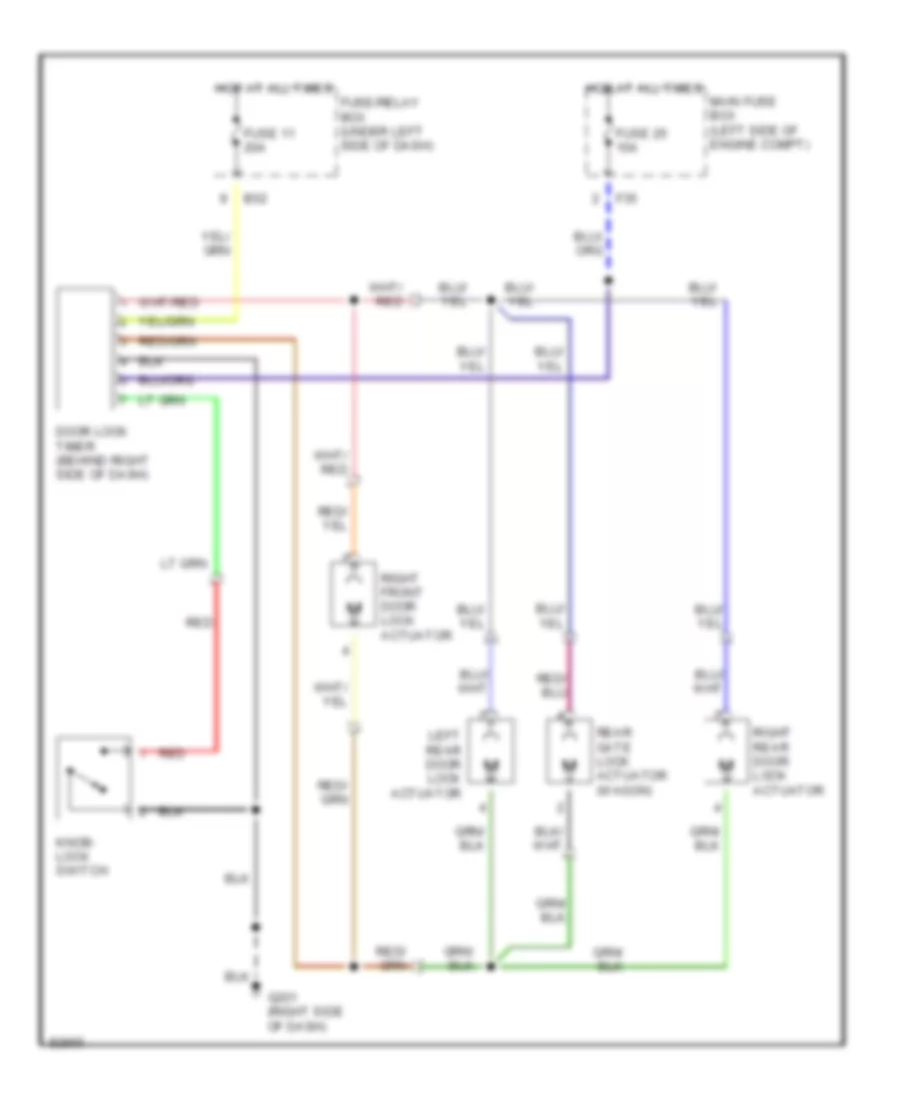
Power Door Lock Wiring Diagram for Subaru Impreza Brighton 1997
List of elements for Power Door Lock Wiring Diagram for Subaru Impreza Brighton 1997:
- B52
- Door lock timer (behind right side of dash)
- F35
- Fuse 11 20a
- Fuse 25 10a
- Fuse/relay box (under left side of dash)
- G201 (right side of dash)
- Hot at all times
- Knob- lock switch
- Left rear door lock actuator
- Main fuse box (left side of engine compt)
- Rear gate lock actuator (wagon)
- Red
- Right front door lock actuator
- Right rear door lock actuator
POWER MIRRORS
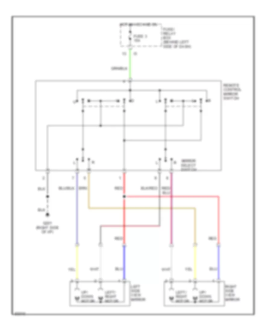
Power Mirror Wiring Diagram for Subaru Impreza Brighton 1997
List of elements for Power Mirror Wiring Diagram for Subaru Impreza Brighton 1997:
- Fuse 3 15a
- Fuse/ relay box (behind left side of dash)
- G201 (right side of i/p)
- Hot in acc and on
- Left side view mirror
- Left/ right m
- Mirror select switch
- Motor
- Red
- Remote control mirror switch
- Right side view mirror
- Up/ down m
POWER TOP/SUNROOF
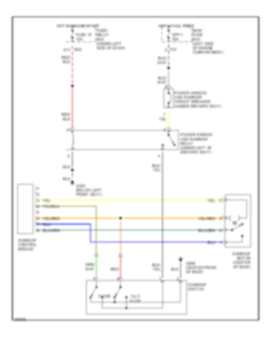
Sunroof Wiring Diagram for Subaru Impreza Brighton 1997
List of elements for Sunroof Wiring Diagram for Subaru Impreza Brighton 1997:
- B52 e11
- Close
- F37
- Fuse 15 10a
- Fuse/ relay box (under left side of dash)
- G300 (below left front seat)
- G908 (center front of roof)
- Hot at all times
- Hot in on and start
- Main fuse box (left side of engine compartment)
- Power window and sunroof circuit breaker (under driver's seat)
- Power window and sunroof relay (under left of driver's seat)
- Red
- Spf-1 30a
- Sunroof control module
- Sunroof motor (center of roof)
- Sunroof switch
- Tilt/ slide
POWER WINDOWS
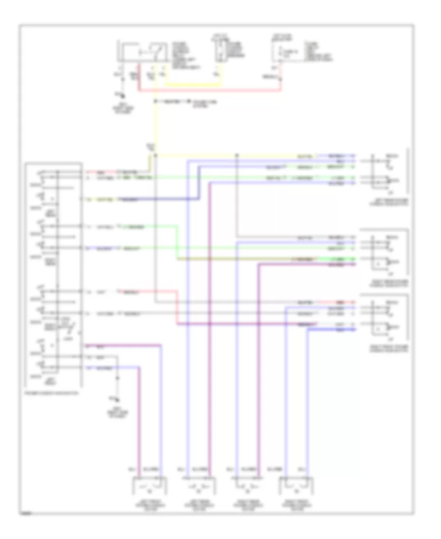
Power Window Wiring Diagram for Subaru Impreza Brighton 1997
List of elements for Power Window Wiring Diagram for Subaru Impreza Brighton 1997:
- Down
- E11
- Fuse 15 10a
- Fuse/ relay box (behind left side of dash)
- G201 (right side of dash)
- Hot at all times
- Hot in on and start
- Left front
- Left front power window motor
- Left rear
- Left rear power window motor
- Left rear power window sub switch
- Lock
- Lock- out switch
- Power tops system
- Power window circuit breaker
- Power window main switch
- Power window/ sunroof relay (under left side of driver's seat)
- Red
- Right front
- Right front power window motor
- Right front power window sub switch
- Right rear
- Right rear power window motor
- Right rear power window sub switch
RADIO
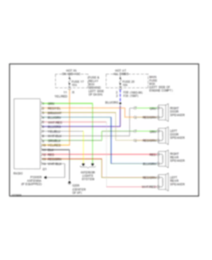
Radio Wiring Diagrams for Subaru Impreza Brighton 1997
List of elements for Radio Wiring Diagrams for Subaru Impreza Brighton 1997:
- (center of i/p)
- F28 (1993-96) f35 (1997)
- Fuse & relay box (behind left side of dash)
- Fuse 17 15a
- Fuse 25 10a
- G206
- Hot at all times
- Hot in on and acc
- I21
- Interior lights system
- Left door speaker
- Left rear speaker
- Main fuse box (left side of engine compt)
- Power antenna (if equipped)
- Radio
- Red
- Right door speaker
- Right rear speaker
SHIFT INTERLOCKS
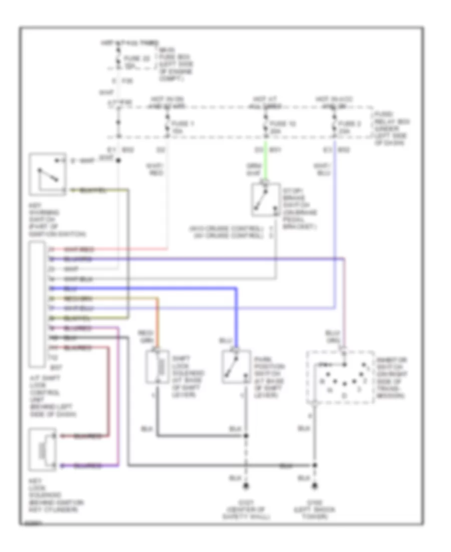
Shift Interlock Wiring Diagram for Subaru Impreza Brighton 1997
List of elements for Shift Interlock Wiring Diagram for Subaru Impreza Brighton 1997:
- (w/o cruise control) (w/ cruise control)
- A/t shift lock control unit (behind left side of dash)
- B51 d3
- B52 e3
- B57
- F35
- F40 a7
- Fuse 1 15a
- Fuse 12 20a
- Fuse 2 20a
- Fuse 22 15a
- Fuse/ relay box (under left side of dash)
- G102 (left shock tower)
- G121 (center of safety wall)
- Hot at all times
- Hot in acc and on
- Hot in on and start
- Inhbitor switch (on right side of trans- mission)
- Key lock solenoid (behind ignition key cylinder)
- Key warning switch (part of ignition switch)
- Main fuse box (left side of engine compt)
- Park position switch (at base of shift lever)
- Shift lock solenoid (at base of shift lever)
- Stop/ brake switch (on brake pedal bracket)
STARTING/CHARGING
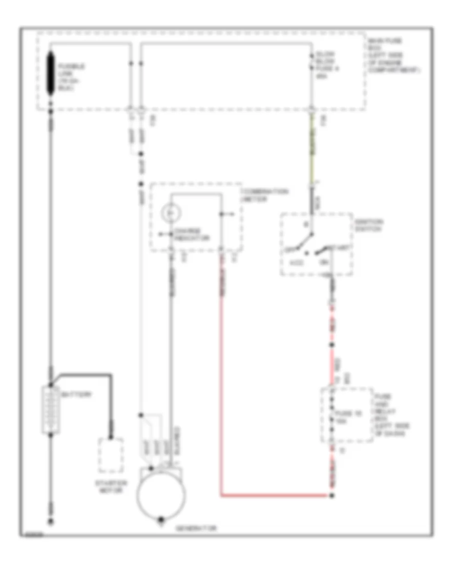
Charging Wiring Diagram for Subaru Impreza Brighton 1997
List of elements for Charging Wiring Diagram for Subaru Impreza Brighton 1997:
- Acc
- B52
- Battery
- Charge indicator
- Combination meter
- F36
- F38
- Fuse 15 10a
- Fuse and relay box (left side of dash)
- Generator
- I10
- I12
- Ignition switch
- Main fuse box (left side of engine compartment)
- Nca
- Nca b
- Off
- Red
- Slow blow fuse 4 45a
- Start
- Starter motor
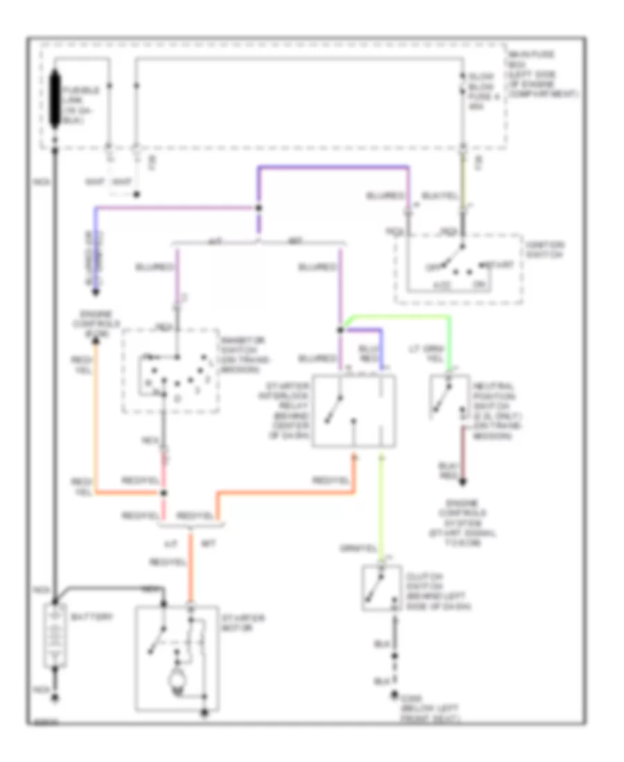
Starting Wiring Diagram for Subaru Impreza Brighton 1997
List of elements for Starting Wiring Diagram for Subaru Impreza Brighton 1997:
- A/t
- Acc
- Battery
- Clutch switch (behind left side of dash)
- Engine controls (ecm)
- Engine controls system (start signal to ecm)
- F36
- F38
- G300 (below left front seat)
- Ignition switch
- Inhibitor switch (on trans- mission)
- M/t
- Main fuse box (left side of engine compartment)
- Nca
- Neutral position switch (2.2l only) (on trans- mission)
- Off
- Slow blow fuse 4 45a
- Start
- Starter interlock relay (behind center of dash)
- Starter motor
SUPPLEMENTAL RESTRAINTS
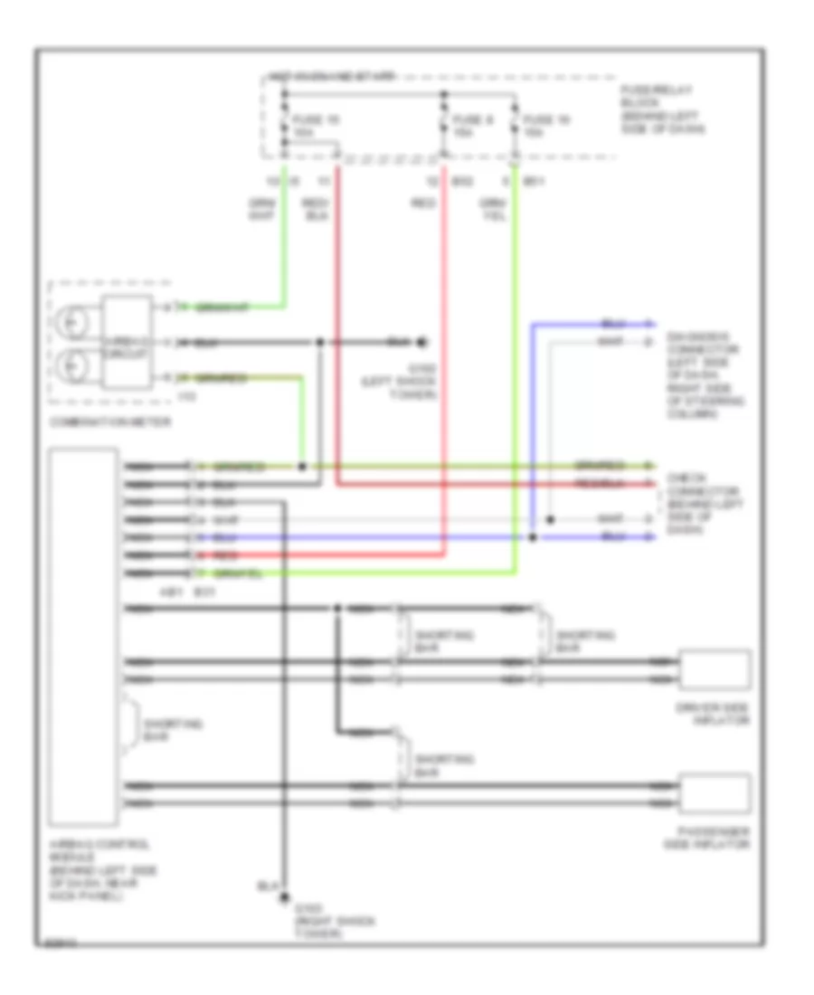
Supplemental Restraint Wiring Diagram for Subaru Impreza Brighton 1997
List of elements for Supplemental Restraint Wiring Diagram for Subaru Impreza Brighton 1997:
- Airbag circuit
- Airbag control module (behind left side of dash, near kick panel)
- B31 ab1
- B51
- B52
- Check connector (behind left side of dash)
- Combination meter
- Diagnosis connector (left side of dash, right side of steering column)
- Driver side inflator
- Fuse 15 10a
- Fuse 16 15a
- Fuse 8 15a
- Fuse/relay block (behind left side of dash)
- G102 (left shock tower)
- G103 (right shock tower)
- Hot in on and start
- I13
- Nca
- Passenger side inflator
- Red
- Shorting bar
TRANSMISSION
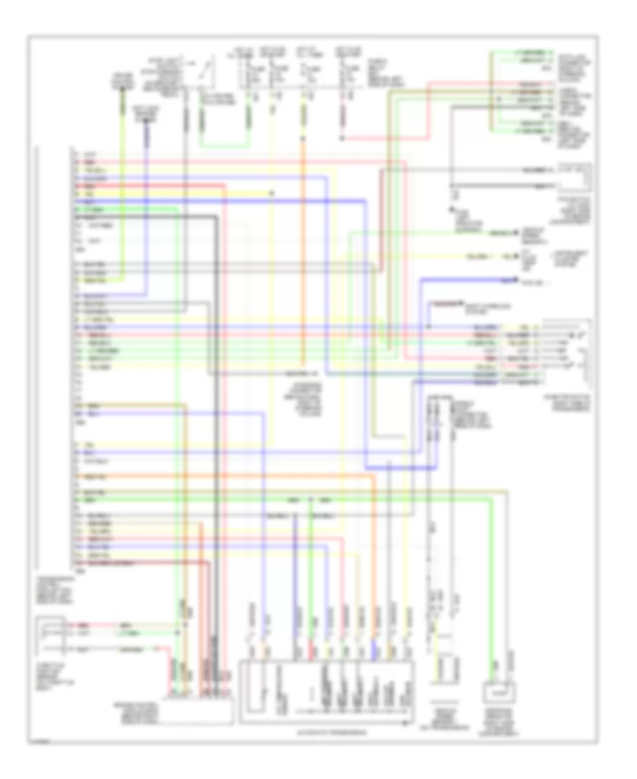
A/T Wiring Diagram for Subaru Impreza Brighton 1997
List of elements for A/T Wiring Diagram for Subaru Impreza Brighton 1997:
- (right side of engine compartment)
- (right side of transmission)
- (w/ cruise)
- (w/o cruise)
- A/t fluid temp ind
- Anti-lock brakes system
- Atf temperature sensor
- Automatic transmission
- Awd solenoid
- B40
- B51
- B52
- B54
- B55
- B56
- B78
- B79
- Check connector (behind left side of dash)
- Connector (left side of dash)
- Cruise control system
- Data link connector (right of steering column)
- Diagnosis connector (behind dash, right of steering column)
- Dropping resistor
- Engine control module (ecm) (behind right side of dash)
- F40
- Fuse & relay box (behind left side of dash)
- Fuse 10a
- Fuse 15a
- Fuse 20a
- Fwd ind
- Fwd switch (w/ awd) (right side of engine compartment)
- G108 (left radiator support)
- Hot at all times
- Hot in on hot at all times
- Hot in on or start
- Inhibitor switch
- Instrument cluster system
- Lock-up solenoid
- Nca
- Obd ii
- Or start
- Red
- Service
- Shield joint connector (behind left side of dash)
- Shift interlock system
- Shift solenoid 1
- Shift solenoid 3
- Solenoid 2 shift
- Solenoid line pressure
- Stop light switch/ stop & brake switch (on bracket above brake pedal)
- Throttle position sensor (on throttle body)
- Transmission control module (tcm) (behind left side of dash)
- Vehicle speed sensor 1 (on transmission)
- Vehicle speed sensor 2
WARNING SYSTEMS
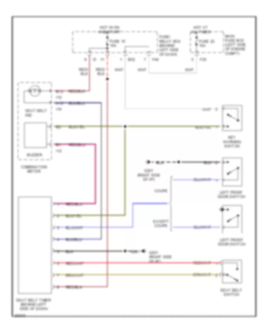
Warning System Wiring Diagrams for Subaru Impreza Brighton 1997
List of elements for Warning System Wiring Diagrams for Subaru Impreza Brighton 1997:
- A13
- B13
- B52
- Buzzer
- Combination meter
- Coupe
- Except coupe
- F35
- F40
- Fuse 15 10a
- Fuse 22 15a
- Fuse/ relay box (behind left side of dash)
- G201 (right side of i/p)
- Hot at all times
- Hot in on and start
- I10
- I12
- Key warning switch
- Left front door switch
- Main fuse box (left side of engine compt)
- Seat belt ind
- Seat belt switch
- Seat belt timer (behind left side of dash)
WIPER/WASHER
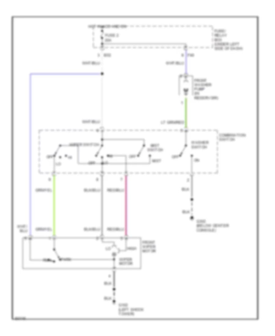
2-Speed Wiper/Washer Wiring Diagram for Subaru Impreza Brighton 1997
List of elements for 2-Speed Wiper/Washer Wiring Diagram for Subaru Impreza Brighton 1997:
- B52
- Combination switch
- F40
- Front washer pump (in reservoir)
- Front wiper motor
- Fuse 2 20a
- Fuse/ relay box (under left side of dash)
- G102 (left shock tower)
- G302 (below center console)
- High
- Hot in acc and on
- Mist
- Mist switch
- Off
- Park
- Run
- Washer switch
- Wiper motor
- Wiper switch
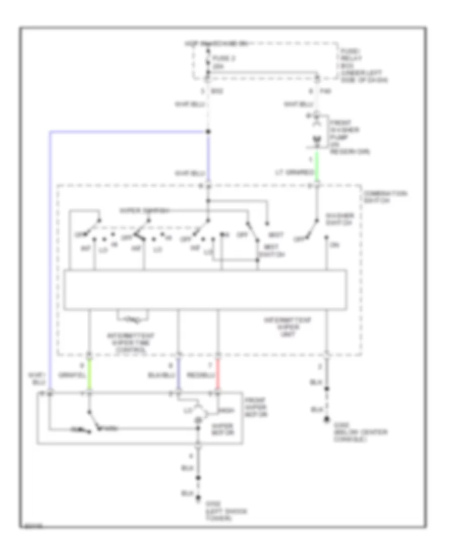
Interval Wiper/Washer Wiring Diagram for Subaru Impreza Brighton 1997
List of elements for Interval Wiper/Washer Wiring Diagram for Subaru Impreza Brighton 1997:
- B52
- Combination switch
- F40
- Front washer pump (in reservoir)
- Front wiper motor
- Fuse 2 20a
- Fuse/ relay box (under left side of dash)
- G102 (left shock tower)
- G302 (below center console)
- High
- Hot in acc and on
- Int
- Intermittent wiper time control
- Intermittent wiper unit
- Mist
- Mist switch
- Off
- Park
- Run
- Washer switch
- Wiper motor
- Wiper switch
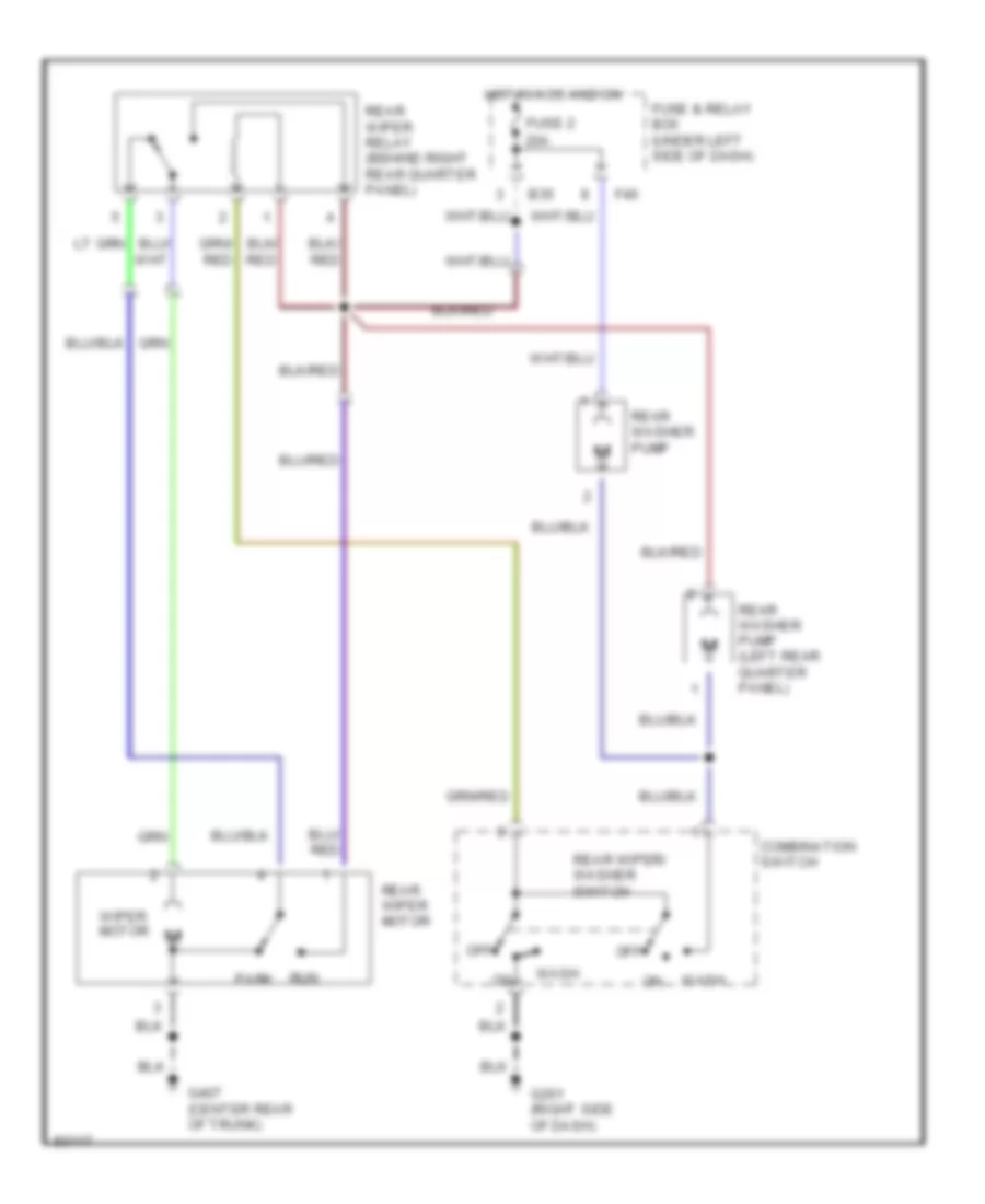
Rear Washer/Wiper Wiring Diagram for Subaru Impreza Brighton 1997
List of elements for Rear Washer/Wiper Wiring Diagram for Subaru Impreza Brighton 1997:
- B35
- Combination switch
- F40
- Fuse & relay box (under left side of dash)
- Fuse 2 20a
- G201 (right side of dash)
- G407 (center rear of trunk)
- Hot in acc and on
- Off
- Park
- Rear washer pump
- Rear washer pump (left rear quarter panel)
- Rear wiper motor
- Rear wiper relay (behind right rear quarter panel)
- Rear wiper/ washer switch
- Run
- Wash
- Wiper motor

 Čeština
 Dansk
Dansk Deutsch
 Ελληνικά
 English
 English
 Español
 Suomi
Suomi Français
 Français
 עברית
עברית Hrvatski
 Magyar
 Italiano
 日本語
日本語 한국어
한국어 Nederlands
 Polski
 Português
 Português
 Română
 Русский
 Slovenčina
 Slovenščina
 Türkçe
 中文 (中国)