AIR CONDITIONING
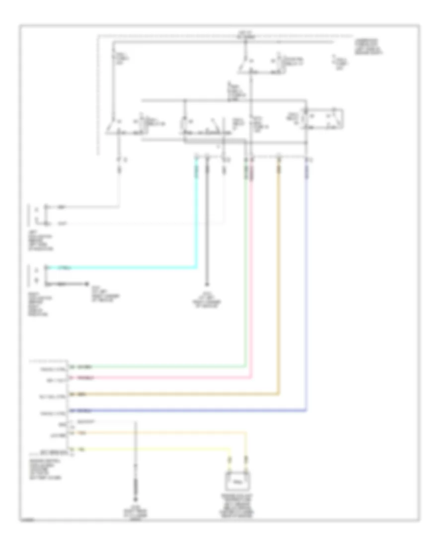
Automatic A/C Wiring Diagram (1 of 2) for Suzuki XL7 Luxury 2009
 https://portal-diagnostov.com/license.html
Automotive Electricians Portal FZCO
Automotive Electricians Portal FZCO
https://portal-diagnostov.com/license.html
https://portal-diagnostov.com/license.html
Automotive Electricians Portal FZCO
Automotive Electricians Portal FZCO
List of elements for Automatic A/C Wiring Diagram (1 of 2) for Suzuki XL7 Luxury 2009:
- (left side of dash) inside air temperature sensor
- (on hvac module)
- (on left side of hvac assembly)
- 5-volt ref
- Air bag display fuse 25 10a
- Air temperature actuator (in hvac assembly)
- Ambient air temperature sensor (below lf headlight, on bumper bar)
- Ambient light sensor (upper left dash trim panel)
- Batt pos volt
- Body control module (bcm) (center of dash, behind hvac control module)
- Computer data lines system
- Ctrl sply vol
- Def rly ctrl
- Defogger system
- Dimming sig
- Dimming sply
- Dr ctrl
- Dr pos sig
- Drv sens sig
- Evaporator temperature sensor (in engine compt, next to expansion valve block)
- G201 (behind right front kick panel)
- G203 (lower center of dash, on i/p fuse block)
- Gnd
- Hot at all times
- Hot w/ ign 1 relay 31 energized
- Hvac control module (at center of dash)
- Hvac/rfa fuse 15 10a
- I/p fuse block (center of dash, beneath right side of radio)
- Ign volt
- Interior lights system
- Low ref
- Low spd lan
- Lower air temperature sensor (on lower right side of temperature actuator)
- Mode actuator
- Mode dr ctrl
- Mode dr sig
- Mode mtr ctrl
- Mtr spd ctrl
- Pass sens sig
- Pnk
- Pos sig
- Re-circulation dr ctrl
- Rear a/c circuit
- Recirculation actuator
- Sens sig
- Tan
- Temp ctrl
- Temp dr ctrl
- Temp mtr
- Temp mtr ctrl
- Temp sens sig
- Temp sw sig
- Underhood fuse block (left side of engine compt)
- Upper air temperature sensor (on upper right side of temperature actuator)
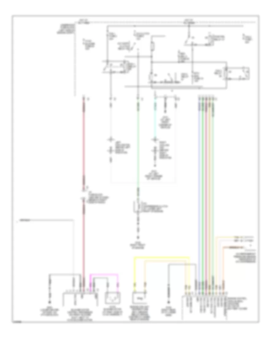
Automatic A/C Wiring Diagram (2 of 2) for Suzuki XL7 Luxury 2009
List of elements for Automatic A/C Wiring Diagram (2 of 2) for Suzuki XL7 Luxury 2009:
- 87a
- A/c clutch fuse 8 10a
- A/c comp/ clutch relay 46
- A/c compressor clutch (at lower left front of engine)
- A/c refrigerant pressure sensor (near back of a/c compressor)
- Blower motor control processor (on front blower duct, next to hvac blower motor)
- Clutch rly ctrl
- Ect sens sig
- Emm dev 2 fuse 20 15a
- Engine control module (ecm) (mounted on top of battery cover)
- Engine coolant temperature (ect) sensor (below brake master cylinder, rear of engine)
- Etc/ ecm fuse 16 15a
- Fan 1 fuse 2 30a
- Fan 1 relay
- Fan 2 fuse 1 30a
- Fan 2 relay
- Fan 3 relay
- Fan rly ctrl
- G101 (at left front corner of vehicle)
- G108 (right front of engine)
- G109 (right rear of cylinder head)
- G203 (lower center of dash, on i/p fuse block)
- Gnd
- Hot at all times
- Hvac blower fuse 54 40a
- Hvac blower motor (at right side of hvac assembly)
- I/p fuse block (center of dash, beneath right side of radio)
- Ign volt
- Left cooling fan (behind left side of radiator)
- Low ref
- Press sens sig
- Pwr/trn relay 47
- Right cooling fan (behind right side of radiator)
- Rly coil ctrl
- Spd ctrl
- Tan
- Underhood fuse block (left side of engine compt)
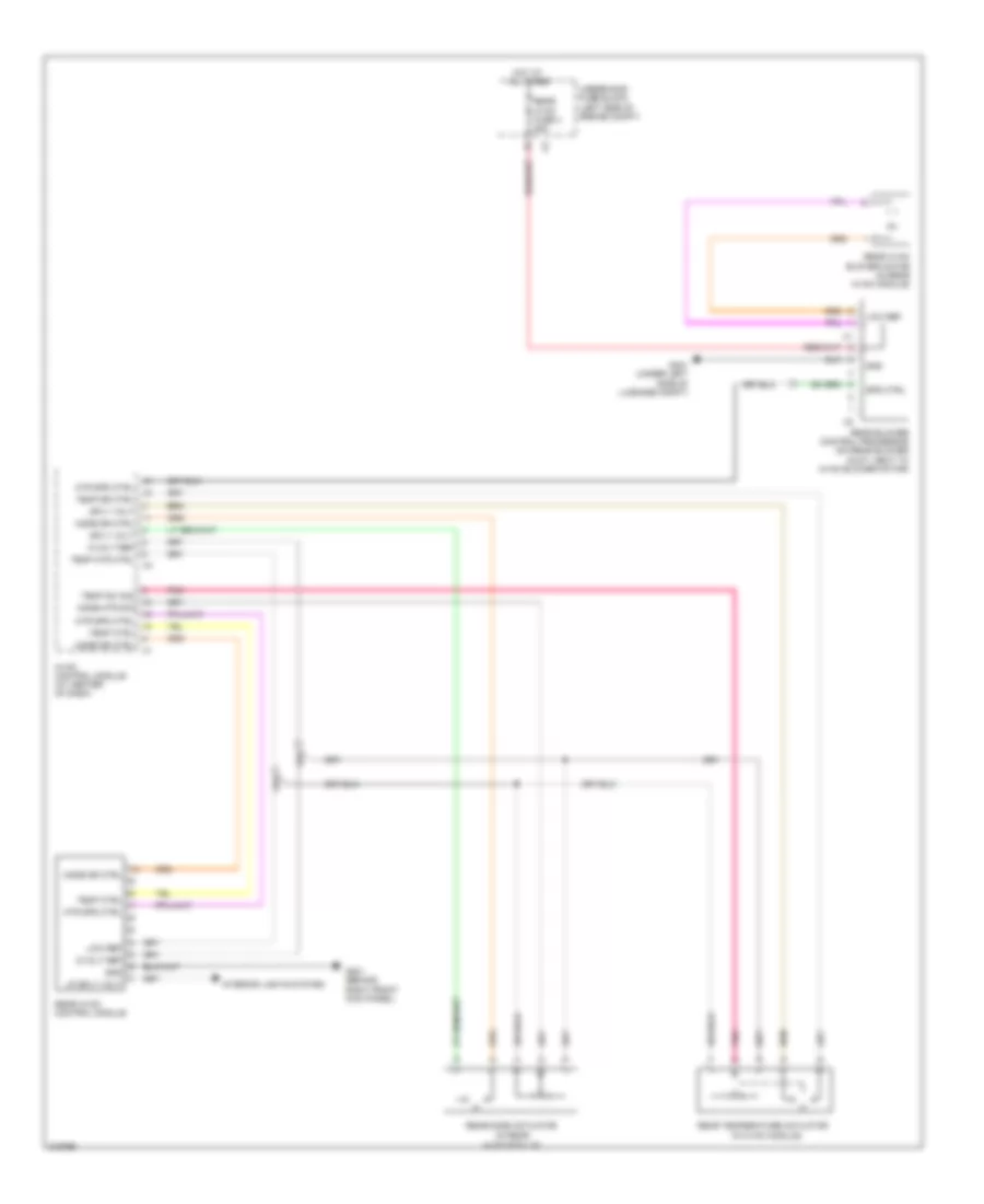
Rear A/C Wiring Diagram for Suzuki XL7 Luxury 2009
List of elements for Rear A/C Wiring Diagram for Suzuki XL7 Luxury 2009:
- (in hvac module)
- (in rear
- 5-volt ref
- G201 (behind right front kick panel)
- G401 (under left side of luggage compt)
- Gnd
- Hot at all times
- Hvac control module (at center of dash)
- Hvac module)
- Interior lights system
- Low ref
- Lp sply volt
- Mode dr ctrl
- Mode mtr sig
- Mtr spd ctrl
- Pnk
- Rear blower control processor (on rear blower duct, next to hvac blower motor)
- Rear hvac blower motor (in rear hvac module)
- Rear hvac control module
- Rear hvac fuse 4 25a
- Rear mode actuator
- Rear temperature actuator
- Spd ctrl
- Sply volt
- Temp ctrl
- Temp dr ctrl
- Temp mtr ctrl
- Temp sw sig
- Underhood fuse block (left side of engine compt)
ANTI-LOCK BRAKES
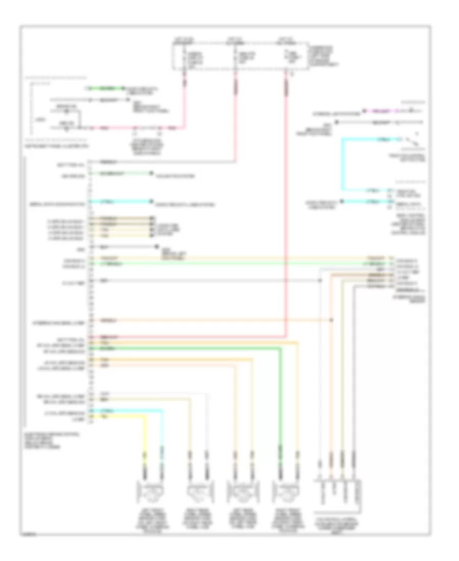
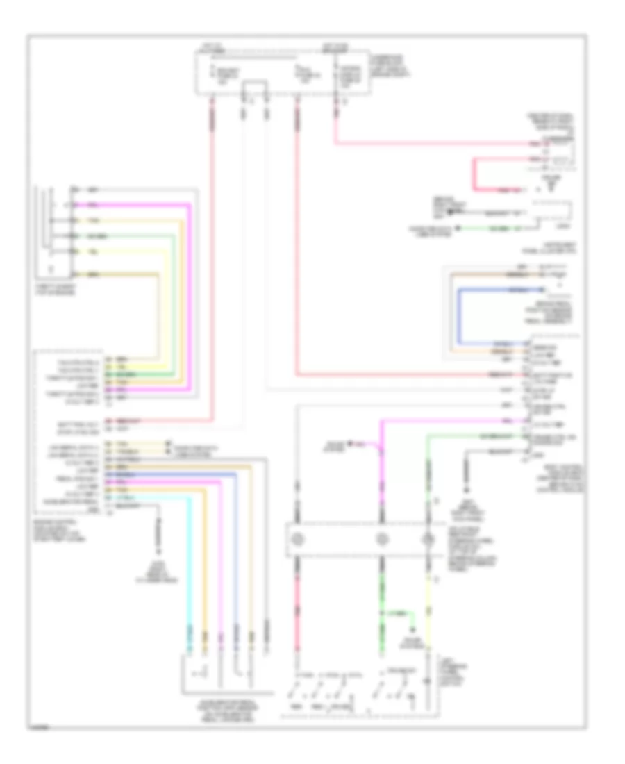
Anti-lock Brakes Wiring Diagram for Suzuki XL7 Luxury 2009
List of elements for Anti-lock Brakes Wiring Diagram for Suzuki XL7 Luxury 2009:
- 12 volt ref
- Abs fuse 7 25a
- Abs ind
- Abs mtr fuse 49 40a
- Airbag display fuse 25 10a
- Batt pos vol
- Body control module (bcm) (center of dash, behind hvac control module)
- Brake ind
- Can bus hi
- Can bus lo
- Computer data
- Computer data lines system
- Electronic brake control module (ebcm) (below brake master cylinder)
- G201 (behind right front kick panel)
- G205 (behind left kick panel)
- Gnd
- Hi spd gmlan bus +
- Hi spd gmlan bus -
- Hot at all times
- Hot in on or start
- I/p fuse block (center of dash, beneath right side of radio)
- Instrument panel cluster (ipc)
- Interior lights system
- Left front wheel speed sensor (wss) (on left front wheel steering knuckle)
- Left rear wheel speed sensor (wss) (on left rear wheel hub)
- Lf whl spd sens sig
- Lines system
- Lo ref
- Logic
- Lr whl spd sens lo ref
- Lr whl spd sens sig
- Navigation system
- Nca
- Pnk
- Rf whl spd sens lo ref
- Rf whl spd sens sig
- Right front wheel speed sensor (wss) (on right front wheel steering knuckle)
- Right rear wheel speed sensor (wss) (on right rear wheel hub)
- Rr whl spd sens lo ref
- Rr whl spd sens sig
- Serial data
- Serial data communication
- Steering ang sens lo ref
- Steering angle sensor
- Tan
- Traction control switch (tcs)
- Traction ctrl sw sig
- Underhood fuse block (left side of engine compartment)
- Veh spd sig
- Yaw rate & lateral accelerator sensor (under passenger seat)
ANTI-THEFT
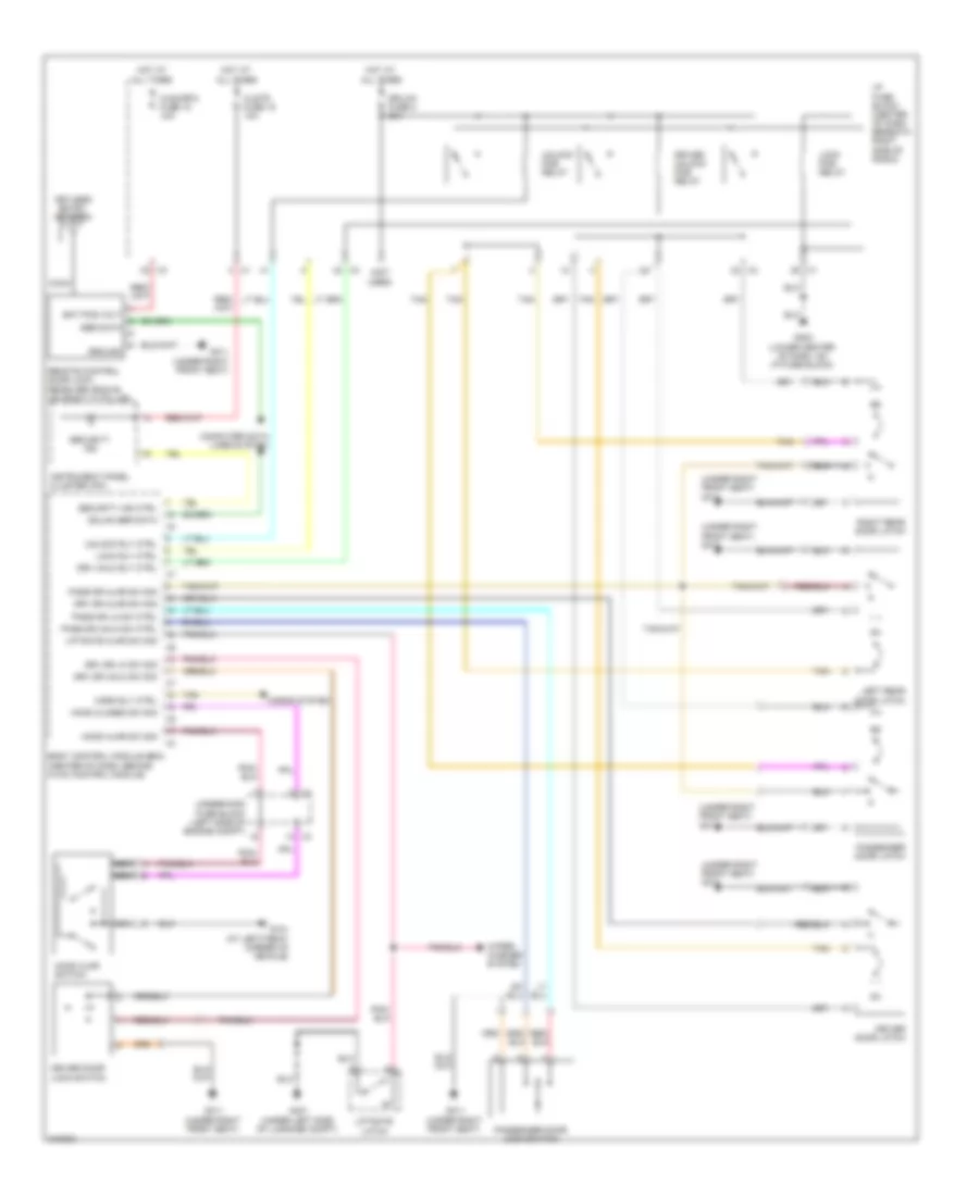
Forced Entry Wiring Diagram for Suzuki XL7 Luxury 2009
List of elements for Forced Entry Wiring Diagram for Suzuki XL7 Luxury 2009:
- (not used)
- (under right front seat) g311
- Bat pos volt
- Body control module (bcm) (center of dash, behind hvac control module)
- Clstr fuse 18 10a
- Coax
- Computer data lines system
- Dr/lck fuse 8 25a
- Driver door latch
- Driver door lock switch
- Driver unlock pcb relay
- Drv dr ajar sw sig
- Drv dr lk sw sig
- Drv dr unlk sw sig
- Drv unlk rly ctrl
- G101 (at left front corner of vehicle)
- G203 (lower center of dash, on i/p fuse block)
- G311 (under right front seat)
- G401 (under left side of luggage compt)
- Gmlan ser data
- Ground
- Hood ajar sw sig
- Hood ajar switch
- Hood closed sw sig
- Horn rly ctrl
- Horns system
- Hot at all times
- Hvac/rfa fuse 15 10a
- I/p fuse block (center of dash, beneath right side of radio)
- Instrument panel cluster (ipc)
- Keyless entry antenna
- Left rear door latch
- Liftgate ajar sw sig
- Liftgate latch
- Lock pcb relay
- Lock rly ctrl
- Nca
- Pass dr ajar sw sig
- Pass dr lk sw ctrl
- Pass dr unlk sw ctrl
- Passenger door latch
- Passenger door lock switch
- Remote control door lock receiver (rcdlr) (on right "c" pillar)
- Right rear door latch
- Security ind
- Security ind ctrl
- Ser data
- Tan
- Underhood fuse block (left side of engine compt)
- Unlock pcb relay
- Unlock rly ctrl
- Wiper/ washer system
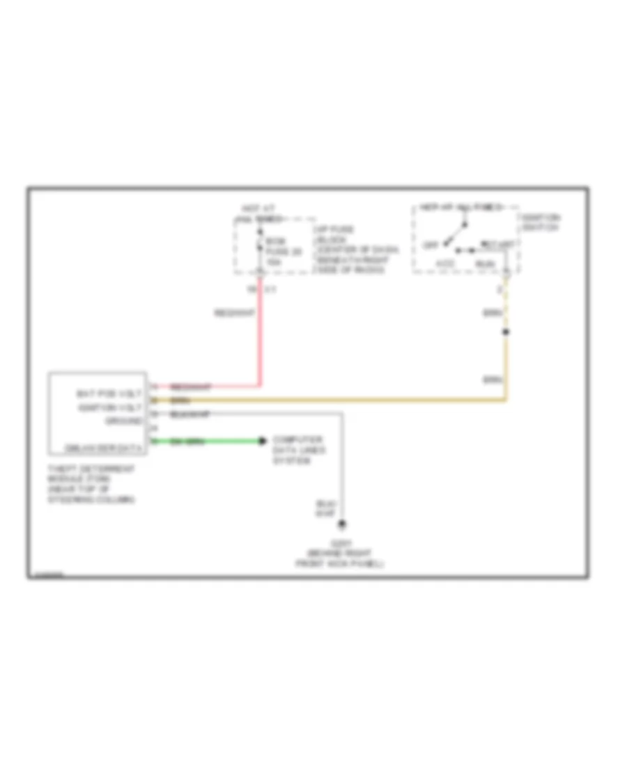
Immobilizer Wiring Diagram for Suzuki XL7 Luxury 2009
List of elements for Immobilizer Wiring Diagram for Suzuki XL7 Luxury 2009:
- Acc
- Bat pos volt
- Bcm fuse 20 10a
- Computer data lines system
- G201 (behind right front kick panel)
- Gmlan ser data
- Ground
- Hot at all times
- I/p fuse block (center of dash, beneath right side of radio)
- Ignition switch
- Ignition volt
- Off
- Run
- Start
- Theft deterrent module (tdm) (near top of steering column)
BODY CONTROL MODULES
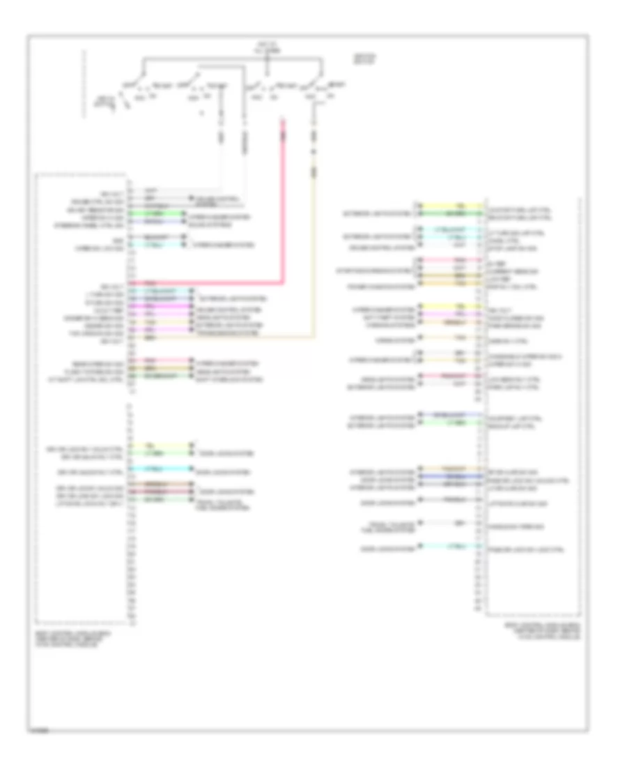
Body Control Modules Wiring Diagram (1 of 2) for Suzuki XL7 Luxury 2009
List of elements for Body Control Modules Wiring Diagram (1 of 2) for Suzuki XL7 Luxury 2009:
- 12volt ref
- 5v ref
- A/t shift lck ctrl sol ctrl
- Acc
- Anti-theft system
- Backup lmp ctrl
- Body control module (bcm) (center of dash, behind hvac control module)
- Chmsl ctrl
- Courtesy lmp ctrl
- Cruise control system
- Cruise ctrl sw sig
- Current sens sig
- Dimmer sw hi beam sig
- Door locks system
- Drv dr lck sw unlck sig
- Drv dr lock rly unlck ctrl
- Drv dr lock sw lock sig
- Drv dr unlck rly ctrl
- Drv dr unlock rly ctrl
- Exterior lights system
- Flash to pass sw sig
- Gnd
- Handle sw open sig
- Hazard sw sig
- Headlights system
- Hood closed sw sig
- Horn rly ctrl
- Horns system
- Hot at all times
- Ign key resistor sig
- Ign volt
- Ignition switch
- Interior lights system
- Key-in switch
- L turn sw sig
- Lf dr ajar sw sig
- Lf turn sig lmp ctrl
- Liftgate ajar sw sig
- Liftgate latch rly sply
- Low beam rly ctrl
- Low ref
- Lr stop/turn lmp ctrl
- Off
- Park brake sw sig
- Park lmp rly ctrl
- Pass dr lock sw lock ctrl
- Pass dr lock sw unlock ctrl
- Pnk
- Power windows system
- R turn sw sig
- Rap rly coil ctrl
- Rear wiper sw sig
- Rf dr ajar sw sig
- Rr stop/turn lmp ctrl
- Shift interlock system
- Sound systems
- Start
- Starting/charging system
- Steering wheel ctrl sig
- Stop lamp sw sig
- Tan
- Tap up/down sw sig
- Transmissions system
- Trunk, tailgate, fuel doors system
- Warning systems
- Windshield wiper sw sig 2
- Wiper sw hi sig
- Wiper sw low sig
- Wiper/washer system
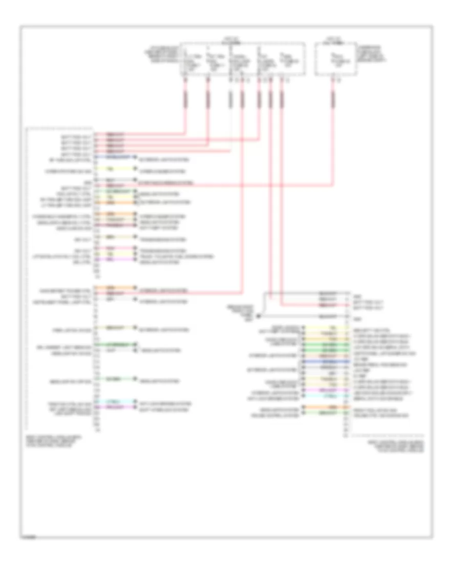
Body Control Modules Wiring Diagram (2 of 2) for Suzuki XL7 Luxury 2009
List of elements for Body Control Modules Wiring Diagram (2 of 2) for Suzuki XL7 Luxury 2009:
- (behind right front kick panel) g201
- 12v ref
- 5v ref
- Anti-lock brakes system
- Anti-theft system
- Batt pos volt
- Bcm fuse 20 10a
- Body control module (bcm) (center of dash, behind hvac control module)
- Brake pedal pos sens sig
- Chmsl/ dim lamp fuse 22 15a
- Computer data lines system
- Cruise control system
- Cruise ctrl ind dimming sig
- Door locks & anti-theft systems
- Drl ambient light sens sig
- Drl ctrl
- Exterior lights system
- Fog lmp rly ctrl
- Front fog lmp sw sig
- Gnd
- Headlamp hi beam rly ctrl
- Headlamp sw off sig
- Headlamp sw on sig
- Headlights system
- Hi spd gmlan ser data bus +
- Hi spd gmlan ser data bus -
- Hood ajar sw sig
- Hot at all times
- I/p fuse block (center of dash, beneath right side of radio)
- Ign volt
- Inadvertent power ctrl
- Instr panel lmp dimmer sw sig
- Instrument panel lamp ctrl
- Int lamps fuse 23 10a
- Interior lights system
- Key capture/column lock shift pos sig
- Led dimm sig/led dimming sply
- Lh trailer turn sig lamp
- Liftgate latch rly coil ctrl
- Low ref
- Low spd gmlan serial data
- Lt trn/ sig fuse 7 15a
- Park lmp sw on sig
- Pnk
- Rf turn sig lmp ctrl
- Rh trailer turn sig lamp
- Rt trn/ sig fuse 11 15a
- Rvc fuse 42 10a
- Security ind ctrl
- Serial data com enable
- Shift interlock system
- Starting/charging system
- Tan
- Traction ctrl sw sig
- Transmissions system
- Trunk, tailgate, fuel doors system
- Underhood fuse block (left side of engine compt)
- Windshield washer rly ctrl
- Wiper mtr park sw sig
- Wiper/washer system
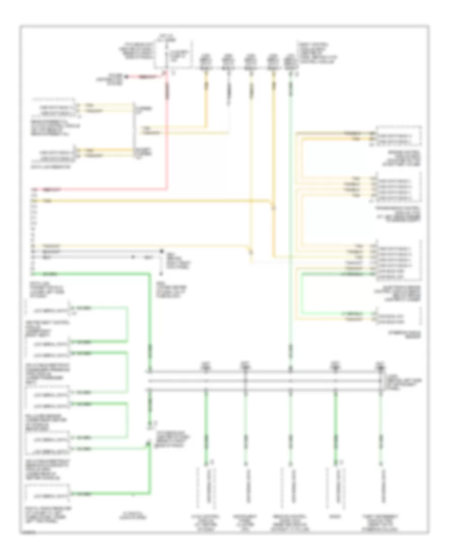
COMPUTER DATA LINES
Computer Data Lines Wiring Diagram for Suzuki XL7 Luxury 2009
List of elements for Computer Data Lines Wiring Diagram for Suzuki XL7 Luxury 2009:
- (not used) b
- (not used) c
- (not used) e
- (not used) j
- 6 speed a/t
- A high data bus (+)
- B high data bus (-)
- Body control module (bcm) (center of dash, behind hvac control module)
- Can bus high
- Can bus low
- Data link connector (dlc) (lower left side of dash)
- Data link resistor
- Digital radio receiver (attached to left wheelhouse, under left trim panel)
- Electronic brake control module (ebcm) (below brake master cylinder)
- Engine control module (ecm) (mounted on top of battery cover)
- Except 6 speed a/t
- G201 (behind right front kick panel)
- G203 (lower center of dash, on i/p fuse block)
- Heated seat control module (under right front seat)
- High data bus (+)
- High data bus (-)
- High serial data bus (+)
- High serial data bus (-)
- Hot at all times
- Hvac control module (at center of dash)
- Hvac/rfa fuse 15 10a
- I/p fuse block (center of dash, beneath right side of radio)
- I/p fuse block (center of dash, beneath right side of radio) x3
- Inflatable restraint passenger presence (pps) module (under passenger seat)
- Inflatable restraint sensing & diagnostic module (sdm) (under rear of center console)
- Instrument panel cluster (ipc)
- Jx200 (behind left side of instrument panel)
- Low serial data
- Low serial serial data
- Power distribution system
- Radio
- Rear differential clutch control module (on top rear of rear differential)
- Remote control door lock receiver (rcdlr) (on right "c" pillar)
- Rollover sensor (under rear center of console, behind sdm)
- Steering angle sensor
- Tan
- Theft deterrent module (tdm) (near top of steering column)
- Transmission control module (tcm) (at left rear corner of engine compt)
- W/ digital audio system
COOLING FAN
Cooling Fan Wiring Diagram for Suzuki XL7 Luxury 2009
List of elements for Cooling Fan Wiring Diagram for Suzuki XL7 Luxury 2009:
- 87a
- Ect sens sig
- Emm dev 2 fuse 20 15a
- Engine control module (ecm) (mounted on top of battery cover)
- Engine coolant temperature (ect) sensor (below brake master cylinder, rear of engine)
- Etc/ ecm fuse 16 15a
- Fan 1 fuse 2 30a
- Fan 1 relay 56
- Fan 2 fuse 1 30a
- Fan 2 relay
- Fan 3 relay
- Fan rly ctrl
- G101 (at left front corner of vehicle)
- G109 (right rear of cylinder head)
- Gnd
- Hot at all times
- Ign 1 volt
- Left cooling fan (behind left side of radiator)
- Low ref
- Pwr/trn relay 47
- Right cooling fan (behind right side of radiator)
- Rly coil ctrl
- Tan
- Underhood fuse block (left side of engine compt)
CRUISE CONTROL
Cruise Control Wiring Diagram for Suzuki XL7 Luxury 2009
List of elements for Cruise Control Wiring Diagram for Suzuki XL7 Luxury 2009:
- (behind right front kick panel) g201
- (center of dash, beneath right side of radio) i/p fuse block
- 12 volt ref
- 5-volt ref
- 5-volt ref 2
- 5-volt ref 3
- Accelerator pedal
- Accelerator pedal position (app) sensor (on accelerator pedal linkage arm)
- Air bag display fuse 25 10a
- Batt pos volt
- Batt positive voltage x4
- Body control module (bcm) (center of dash, behind hvac control module)
- Brake pedal position sensor (on brake pedal assembly)
- Computer data lines system
- Cruise
- Cruise ctrl ind dimming sig
- Cruise ctrl sw sig
- Cruise ind
- Cruise sw
- Ecm bat fuse 33 15a
- Engine control module (ecm) (mounted on top of battery cover)
- G109 (right rear of cylinder head)
- G201 (behind right front kick panel)
- Gnd
- Hot at all times
- Hot in on or start
- Inflatable restraint steering wheel module coil (at top of steering column, behind steering wheel)
- Instrument panel cluster (ipc)
- Lan serial data (+)
- Lan serial data (-)
- Left steering wheel control switch
- Logic
- Low ref
- Nca
- Pedal pos sig 1
- Pnk
- Res +
- Res-
- Rvc fuse 42 10a
- Sens sig
- Sound system
- Sound systems
- Stop lp sw sig
- Stop lp sw sig x5
- Tac mtr ctrl-1
- Tac mtr ctrl-2
- Tan
- Throttle body (top of engine)
- Throttle pos sig 1
- Throttle pos sig 2
- Underhood fuse block (left side of engine compt)
DEFOGGERS
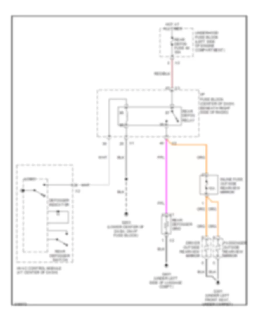
Defoggers Wiring Diagram for Suzuki XL7 Luxury 2009
List of elements for Defoggers Wiring Diagram for Suzuki XL7 Luxury 2009:
- 10a
- Defogger indicator
- Driver outside rearview mirror
- Fuse block (center of dash, beneath right side of radio)
- G203 (lower center of dash, on i/p fuse block)
- G301 (under left front seat, under carpet)
- G401 (under left side of luggage compt)
- Hot at all times
- Hvac control module (at center of dash)
- I/p
- Inline fuse outside rearview mirror
- Logic
- Passenger outside rearview mirror
- Rear defog
- Rear defog fuse 48 30a
- Rear defogger grid
- Rear defogger switch
- Relay
- Underhood fuse block (left side of engine compartment)
ENGINE PERFORMANCE
3.6L
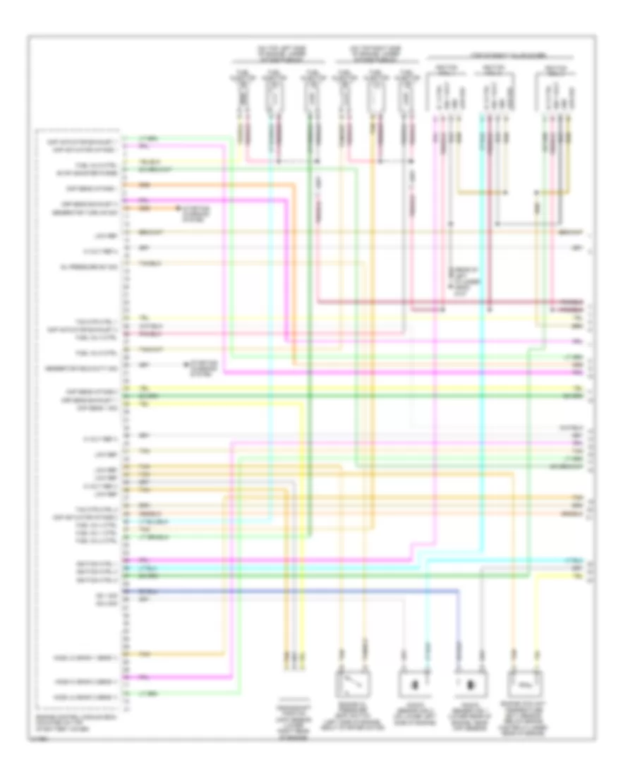
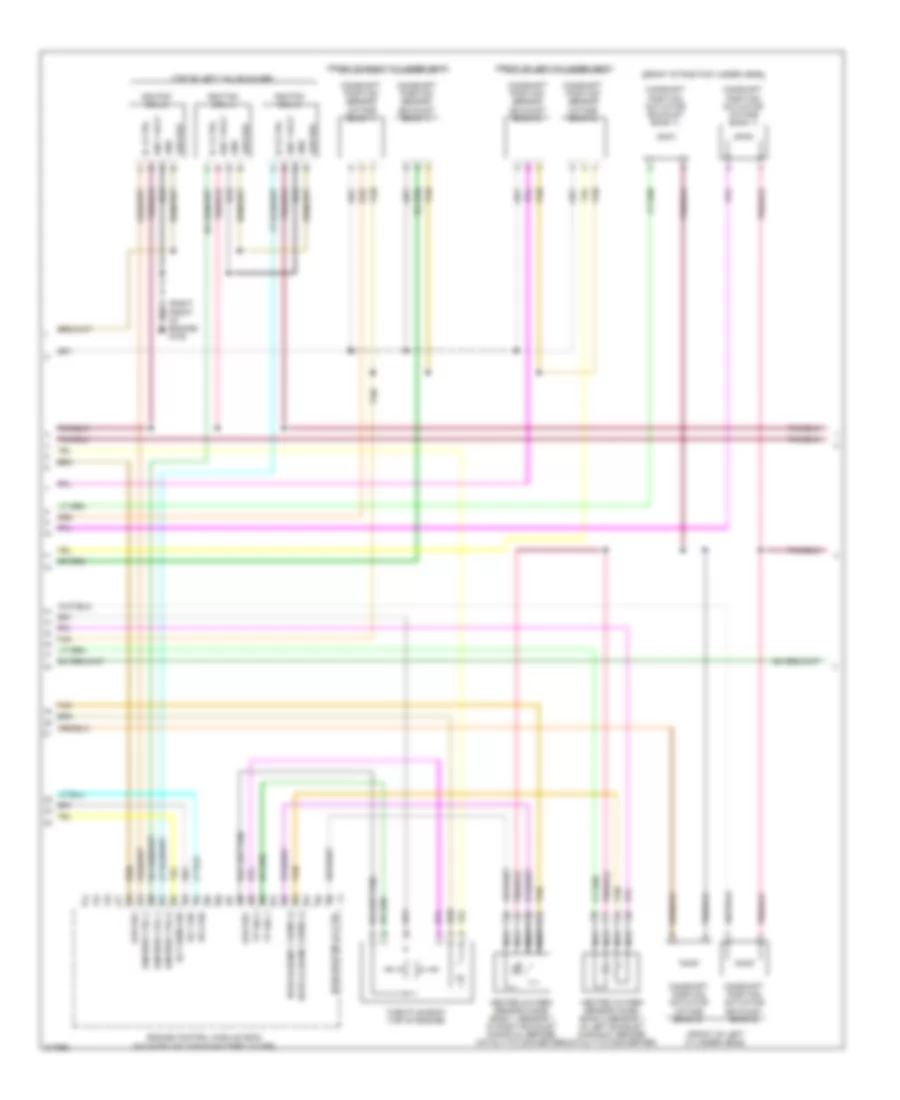
3.6L, Engine Performance Wiring Diagram (1 of 4) for Suzuki XL7 Luxury 2009
List of elements for 3.6L, Engine Performance Wiring Diagram (1 of 4) for Suzuki XL7 Luxury 2009:
- (on top left side of engine, under intake plenum)
- (on top right side of engine, under intake plenum)
- (top of right valve cover)
- 5 volt ref 2
- 5 volt ref 3
- Ckp sens 1 sig
- Cmp actuator exhaust 1
- Cmp actuator exhaust 2
- Cmp actuator intake 1
- Cmp actuator intake 2
- Cmp sens exhaust 1
- Cmp sens exhaust 2
- Cmp sens intake 1
- Cmp sens intake 2
- Crankshaft position (ckp) sensor (lower right rear of engine)
- Engine control module (ecm) (mounted on top of battery cover)
- Engine coolant temperature (ect) sensor (below brake master cylinder, rear of engine)
- Engine oil pressure (eop) switch (left side of engine, about starter motor)
- Evap canister purge
- Fuel inj 1 ctrl
- Fuel inj 2 ctrl
- Fuel inj 3 ctrl
- Fuel inj 4 ctrl
- Fuel inj 5 ctrl
- Fuel inj 6 ctrl
- Fuel injector
- Generator field duty sig
- Generator turn on sig
- Gnd
- Ho2s hi (bank 2 sens 1)
- Ho2s lo (bank 1 sens 1)
- Ho2s lo (bank 2 sens 1)
- Ic 1 ctrl
- Ic 3 ctrl
- Ic 5 ctrl
- Ign 1 volt
- Ignition coil 1
- Ignition coil 3
- Ignition coil 5
- Ignition ctrl 1
- Ignition ctrl 3
- Ignition ctrl 5
- Knock sensor (ks) 1 (lower rear of engine, near ckp sensor)
- Knock sensor (ks) 2 (on lower left side of engine)
- Ks 1 sig
- Ks 2 sig
- Low ref
- Oil pressure sw sig
- Starting/ charging system
- Tac mtr ctrl 1
- Tac mtr ctrl 2
- Tan
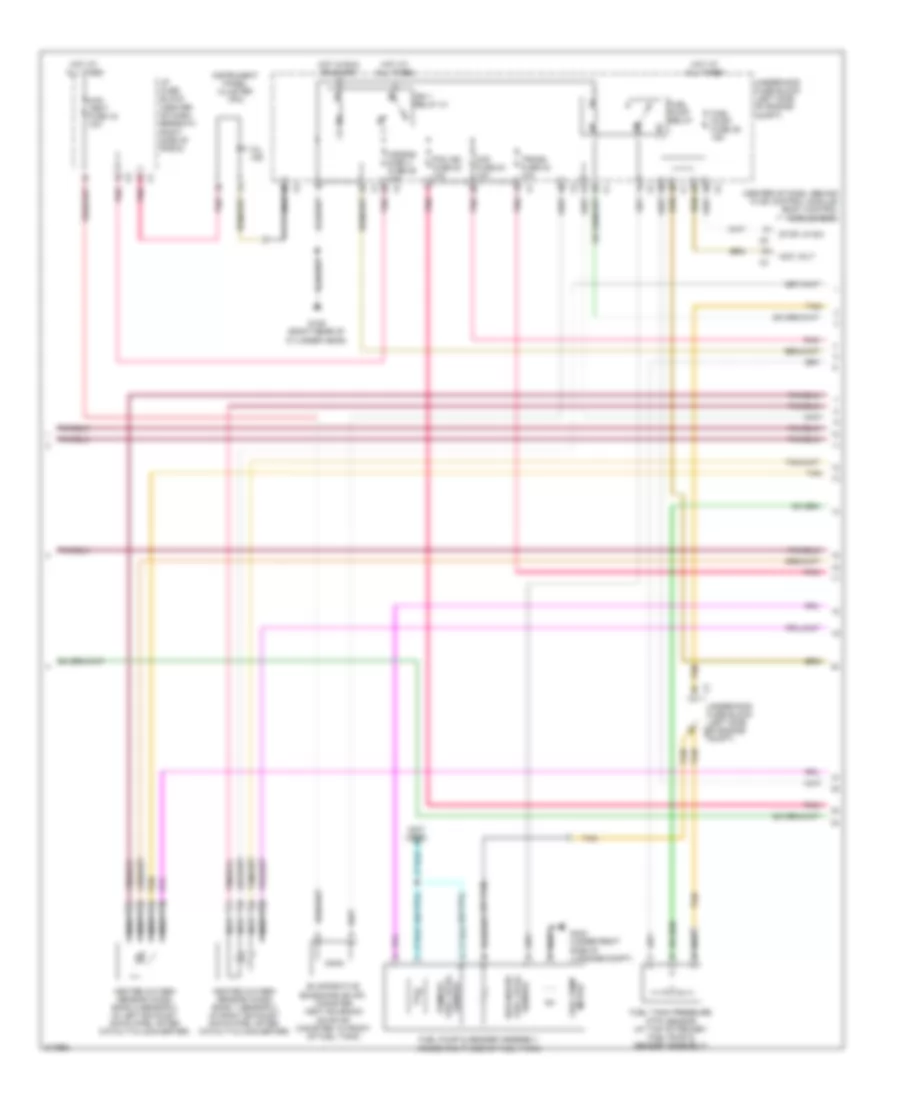
3.6L, Engine Performance Wiring Diagram (2 of 4) for Suzuki XL7 Luxury 2009
List of elements for 3.6L, Engine Performance Wiring Diagram (2 of 4) for Suzuki XL7 Luxury 2009:
- (front of left cylinder head)
- (front of right cylinder head)
- (or tan)
- (right front of engine) g108
- (top of left valve cover)
- Camshaft position actuator (exhaust bank 1)
- Camshaft position actuator (exhaust bank 2)
- Camshaft position actuator (intake bank 1)
- Camshaft position actuator (intake bank 2)
- Camshaft position sensor (exhaust bank 1)
- Camshaft position sensor (exhaust bank 2)
- Camshaft position sensor (intake bank 1)
- Camshaft position sensor (intake bank 2)
- Ect sens sig
- Engine control module (ecm) (mounted on top of battery cover)
- Gnd
- Heated oxygen sensor (ho2s) bank 1 sensor 1 (in right exhaust manifold, before catalytic converter)
- Heated oxygen sensor (ho2s) bank 2 sensor 1 (in left exhaust manifold, before catalytic converter)
- Ho2s heater lo ctrl
- Ho2s hi (bank 1 sens 1)
- Ho2s lo (bank 2 sens 1)
- Ic 2 ctrl
- Ic 4 ctrl
- Ic 6 ctrl
- Ign 1 volt
- Ignition coil 2
- Ignition coil 4
- Ignition coil 6
- Ignition ctrl 2
- Ignition ctrl 4
- Ignition ctrl 6
- Ks 1 sig
- Ks 2 sig
- Low ref
- Nca
- Tan
- Throttle body (top of engine)
- Tp sig 1
- Tp sig 2
3.6L, Engine Performance Wiring Diagram (3 of 4) for Suzuki XL7 Luxury 2009
List of elements for 3.6L, Engine Performance Wiring Diagram (3 of 4) for Suzuki XL7 Luxury 2009:
- (center of dash, behind hvac control module) body control module (bcm)
- (not used)
- (or tan)
- Acc volt
- Air bag disply fuse 25 10a
- Can vent fuse 16 10a
- Evaporative emissions (evap) canister vent solenoid (on evap canister, in front of fuel tank)
- Fuel level sensor
- Fuel pump & sender assembly (inside right side of fuel tank)
- Fuel pump fuse 39 15a
- Fuel pump motor
- Fuel pump relay
- Fuel tank pressure (ftp) sensor (at top of primary fuel pump & sender assembly)
- G109 (right rear of cylinder head)
- G403 (under right side of luggage compt)
- Heated oxygen sensor (ho2s) bank 1 sensor 2 (in right exhaust down pipe, after catalytic converter)
- Heated oxygen sensor (ho2s) bank 2 sensor 2 (in left exhaust down pipe, after catalytic converter)
- Hot at all times
- Hot in run or start
- I/p fuse block (center of dash, beneath right side of radio)
- Ign 1 relay 31
- Instrument panel cluster (ipc)
- Maf fuse 24 10a
- Mil ind
- Nca
- Pcm ign fuse 22 10a
- Pnk
- Secondary
- Sensor fuel level primary
- Stop lp sw
- Tan
- Trans fuse 23 10a
- Underhood fuse block (left side of engine compt)
- Underhood fuse block (left side of engine x2 compt)
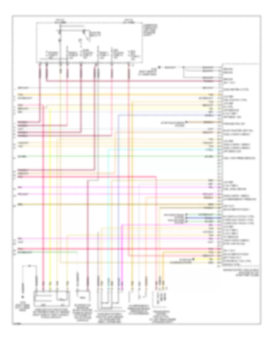
3.6L, Engine Performance Wiring Diagram (4 of 4) for Suzuki XL7 Luxury 2009
List of elements for 3.6L, Engine Performance Wiring Diagram (4 of 4) for Suzuki XL7 Luxury 2009:
- (at left rear corner of engine compt)
- 5 volt ref 1
- 5 volt ref 2
- 5 volt ref 3
- A/c comp clutch rly ctrl
- A/c refrigerant press sig
- A/c refrigerant pressure sensor (near back of a/c compressor)
- Acc volt
- Accelerator pedal position (app) sensor (on accelerator pedal linkage arm)
- Air conditioning system
- App sens 1 sig
- App sens 2 sig
- Batt pos volt
- Cooling fans system
- Ecm bat fuse 33 15a
- Emiso 1 fuse 17 15a
- Emiso 2 fuse 20 15a
- Engine control module (ecm) (mounted on top of battery cover)
- Etc/ecm fuse 16 15a
- Evap canister vent sol
- Evaporative emissions (evap) canister purge solenoid (attached to top of intake manifold)
- Even coils/inj fuse 18 15a
- Fuel level sen sig
- Fuel pump rly ctrl
- Fuel tank press sens sig
- G109 (right rear of cylinder head)
- Gmlan +
- Gmlan -
- Gmlan ser data bus +
- Gmlan ser data bus -
- Ground
- Hi spd cool fan rly ctrl
- Ho2s heater lo ctrl
- Ho2s hi bank 1 sens 2
- Ho2s hi bank 2 sens 2
- Ho2s lo bank 1 sens 2
- Ho2s lo bank 2 sens 2
- Hot at all times
- Iat
- Iat sens sig
- Ign 1 volt
- Lo spd cool fan rly ctrl
- Low ref
- Maf
- Maf sens sig
- Main rly ctrl
- Mass air flow (maf)/intake air temperature (iat) sensor (right side of throttle body, in cold air duct)
- Mil ctrl
- Odd coils/inj fuse 19 15a
- Park/neutral sw
- Pnk
- Pwr/trn relay 47
- Starter rly coil ctrl
- Starting/ charging system
- Starting/charging system
- Stop lamp sw sig
- Tan
- Transmission control module (tcm)
- Underhood fuse block (left side of engine compt)
EXTERIOR LIGHTS
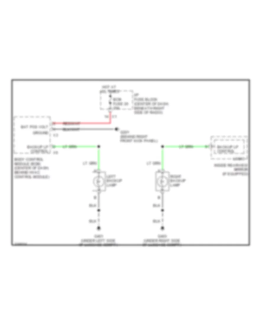
Backup Lamps Wiring Diagram for Suzuki XL7 Luxury 2009
List of elements for Backup Lamps Wiring Diagram for Suzuki XL7 Luxury 2009:
- Backup lp control
- Bat pos volt
- Bcm fuse 20 10a
- Body control module (bcm) (center of dash, behind hvac control module)
- G201 (behind right front kick panel)
- G401 (under left side of luggage compt)
- G403 (under right side of luggage compt)
- Ground
- Hot at all times
- I/p fuse block (center of dash, beneath right side of radio)
- Inside rearview mirror (if equipped)
- Left backup lamp
- Logic
- Right backup lamp
Exterior Lamps Wiring Diagram for Suzuki XL7 Luxury 2009
List of elements for Exterior Lamps Wiring Diagram for Suzuki XL7 Luxury 2009:
- (behind right front kick panel) g201
- (not used)
- (under left side of luggage compt)
- 5-v reference
- Auto
- Bat pos volt
- Body control module (bcm) (center of dash, behind hvac control module)
- Brake pedal position sensor (on brake pedal assembly)
- Center high mounted stop lamp (chmsl)
- Chmsl control
- Chmsl/ dm lamp fuse 22 15a
- Clstr fuse 18 10a
- Computer data lines system
- G101 (at left front corner of vehicle)
- G201 (behind right front kick panel)
- G401
- G401 (under left side of luggage compt)
- G403 (under right side of luggage compt)
- Hazard sw sig
- Hazard switch
- Head
- Headlights system
- Hot at all times
- I/p fuse block (center of dash, beneath right side of radio)
- Instrument panel cluster (ipc)
- Interior lights system
- Lamp ctrl sig
- Left
- Left front marker lamp
- Left front park lamp
- Left front park/ turn signal lamp
- Left license lamp
- Left rear park/ turn signal lamp
- Left tail/ stop lamp
- Left turn ind
- Lh prk/lp fuse 14 10a
- Lh turn sw sig
- Light switch
- Logic
- Low reference
- Lt trn/ sig fuse 7 10a
- Maj
- Min
- Off
- Park
- Park lamp pcb relay
- Park lp control
- Ped pos sens sig
- Prk lp sw sig
- Prk/ lp trlr fuse 10a
- Rh prk/lp fuse 12 10a
- Rh turn sw sig
- Right
- Right front marker lamp
- Right front park lamp
- Right front park/ turn signal lamp
- Right license lamp
- Right rear park/turn signal lamp
- Right tail/ stop lamp
- Right turn ind
- Rt trn/ sig fuse 11 15a
- Sig lp control
- Stop lamp fuse 27 15a
- Stop lamp pcb relay
- Stop lp control
- Tan
- Trailer connector adapter (in left luggage compt, near spare tire)
- Turn signal switch
- Turn signal/ multi-function switch
- Underhood fuse block (left side of engine compt)
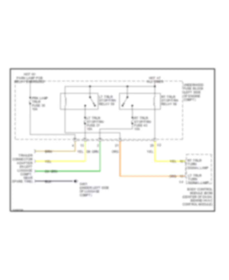
Trailer Tow Wiring Diagram for Suzuki XL7 Luxury 2009
List of elements for Trailer Tow Wiring Diagram for Suzuki XL7 Luxury 2009:
- Body control module (bcm) (center of dash, behind hvac control module)
- G401 (under left side of luggage compt)
- Hot at all times
- Hot w/ park lamp pcb relay energized
- Lt trlr stop/trn fuse 37 10a
- Lt trlr stop/trn relay 59
- Lt trlr turn signal lamp
- Prk lamp trlr fuse 35 10a
- Rt trlr stop/trn fuse 43 10a
- Rt trlr stop/trn relay 58
- Rt trlr turn signal lamp
- Trailer connector adapter (in left luggage compt, near spare tire)
- Underhood fuse block (left side of engine compt)
GROUND DISTRIBUTION
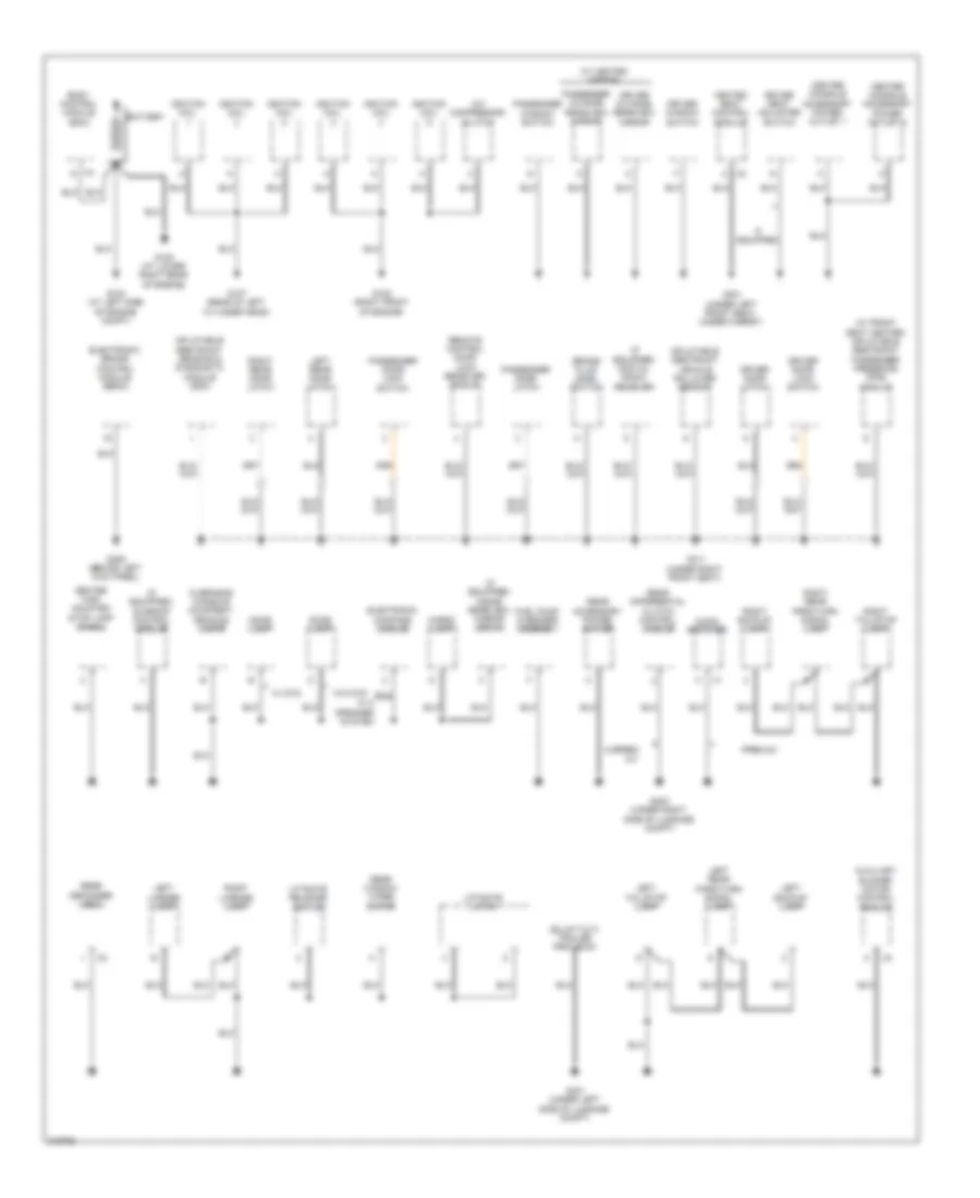
Ground Distribution Wiring Diagram (1 of 2) for Suzuki XL7 Luxury 2009
List of elements for Ground Distribution Wiring Diagram (1 of 2) for Suzuki XL7 Luxury 2009:
- (if equipped) digital radio receiver
- (if equipped) inside rearview mirror (isrvm)
- (if equipped) sunroof control module
- (w/ front seat heater) inflatable restraint passenger presence (pps) module
- (w/ heated mirror)
- 6 speed a/t
- A/c compressor clutch
- Audio amplifier
- Auxiliary blower motor control module
- Battery
- Body control module (bcm)
- Brake fluid level switch
- Cargo lamp
- Center console accessory power outlet 1
- Center console accessory power outlet 2
- Center high mounted stop lamp (chmsl)
- Dome lamp
- Driver door latch
- Driver door lock switch
- Driver outside rearview mirror
- Driver seat adjuster switch
- Driver window switch
- Electronic brake control module (ebcm)
- Electronic compass module
- Fuel pump & sender assembly
- G103 (at left side of engine compt)
- G105 (at lower right rear of engine)
- G107 (rear of left cylinder head)
- G108 (right front of engine)
- G205 (behind left kick panel)
- G301 (under left front seat, under carpet)
- G311 (under right front seat)
- G401 (under left side of luggage compt)
- G403 (under right side of luggage compt)
- Heated seat control module
- If equipped
- Ignition coil
- Inflatable restraint sensing & diagnostic module (sdm)
- Inflatable restraint vehicle rollover sensor
- Left backup lamp
- Left license lamp
- Left rear door latch
- Left rear park/turn signal lamp
- Left tail/stop lamp
- Liftgate latch
- Liftgate release switch
- Overhead console courtesy/ reading lamps
- Passenger door latch
- Passenger door lock switch
- Passenger outside rearview mirror
- Passenger window switch
- Premium
- Rear accessory power outlet
- Rear defogger grid
- Rear differential clutch control module
- Rear window wiper motor
- Remote control door lock receiver (rcdlr)
- Right backup lamp
- Right license lamp
- Right rear door latch
- Right rear park/turn signal lamp
- Right tail/stop lamp
- W/ 8 speaker system
- W/ dvd
- W/o dvd
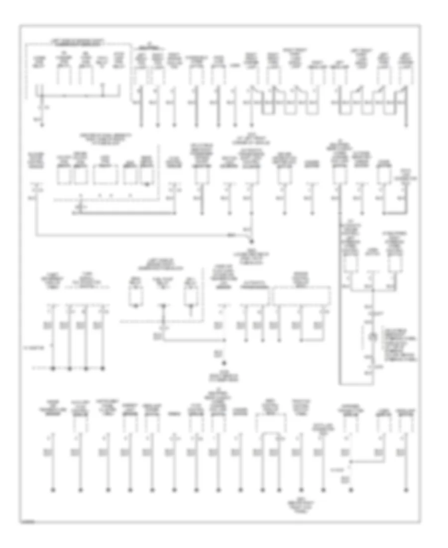
Ground Distribution Wiring Diagram (2 of 2) for Suzuki XL7 Luxury 2009
List of elements for Ground Distribution Wiring Diagram (2 of 2) for Suzuki XL7 Luxury 2009:
- (center of dash, beneath right side of radio) i/p fuse block
- (if equipped)
- (if equipped) rear window wiper/ washer fog lamp switch
- (if equipped) right steering wheel control switch
- (left side of engine compt) underhood fuse block
- (w/ automatic cruise control) left steering wheel control switch
- Ambient light sensor
- Automatic transmission
- Automatic transmission shift lock control solenoid
- Auxiliary hvac control/ module
- Blower motor control module
- Body control module (bcm)
- Cigar lighter
- Crnk relay
- Data link connector (dlc)
- Driver information center (dic) switch
- Driver unlock pcb relay
- Engine control module (ecm)
- F x2
- Fan 2 relay
- Fr washer pcb relay
- Fuel pump relay
- G101 (at left front corner of vehicle)
- G109 (right rear of cylinder head)
- G201 (behind right front kick panel)
- G203 (lower center of dash, on i/p fuse block)
- Hazard switch
- Headlamp dimmer switch
- Headlamp switch
- Hood ajar switch
- Horn
- Horn switch
- Hvac control module
- Ign 1 relay
- Ignition lock solenoid
- Inflatable restraint passenger air bag on/off indicator
- Inflatable restraint steering wheel module coil (at top of steering column, behind steering wheel)
- Infrared transmitter module
- Inside air temperature sensor
- Instrument panel cluster (ipc)
- K x276
- K x277
- Left front fog lamp
- Left front marker lamp
- Left front park lamp
- Left front park/ turn signal lamp
- Left headlamp
- Lock pcb relay
- Mass air flow (maf)/ intake air temperature (iat) sensor
- Nca
- Outside rearview mirror switch
- Radio
- Rap relay
- Rear defog relay
- Right engine cooling fan
- Right front fog lamp
- Right front marker lamp
- Right front park lamp
- Right front park/ turn signal lamp
- Right headlamp
- Rr wash pcb relay
- Stop lamp pcb relay
- Theft deterrent module (tdm)
- Traction control switch (tcs)
- Turn signal/ multifunction switch
- Unlock pcb relay
- Video display
- W/ dvd
- W/ onstar
- Windshield wiper motor
- Wiper pcb relay
HEADLIGHTS
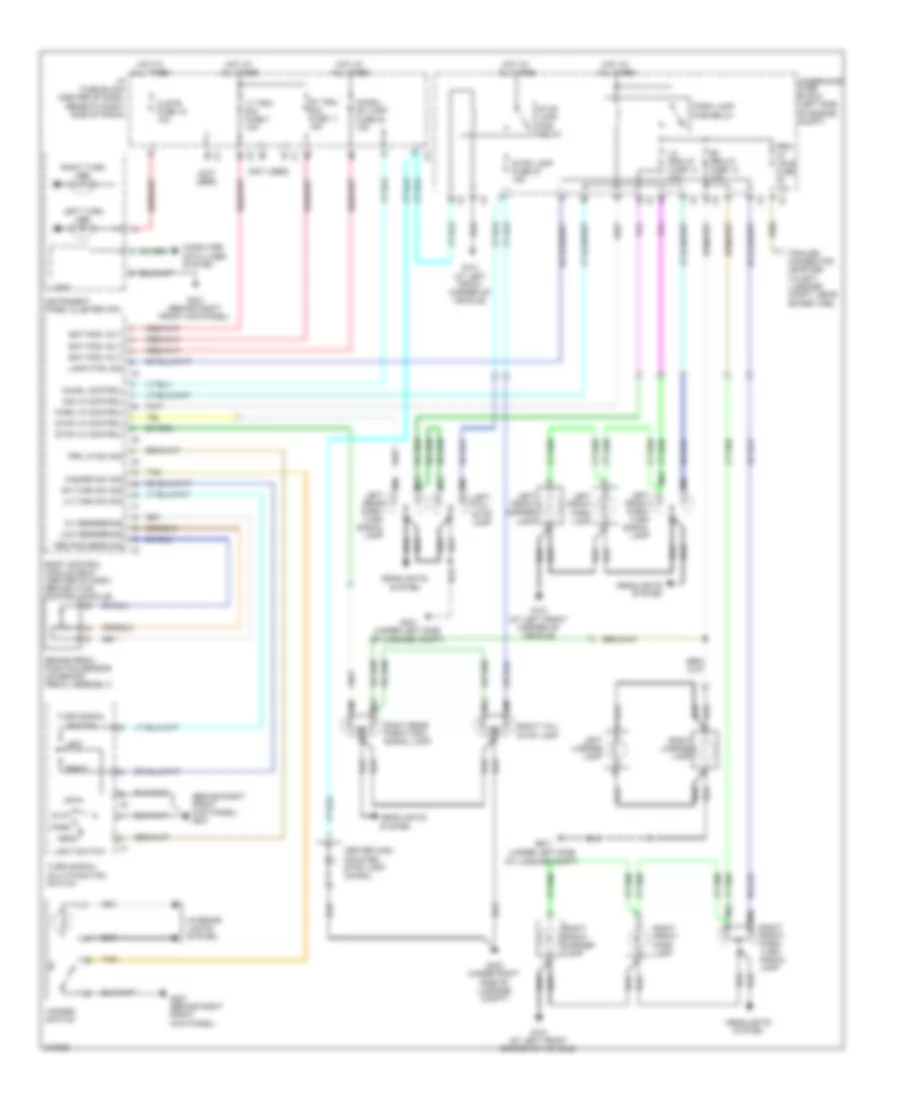
Headlights Wiring Diagram for Suzuki XL7 Luxury 2009
List of elements for Headlights Wiring Diagram for Suzuki XL7 Luxury 2009:
- (at left
- (center of dash,
- Air bag display fuse 25 10a
- Ambient light sensor (upper left dash trim panel)
- Auto
- Behind hvac
- Body control module (bcm)
- Computer data lines system
- Control module)
- Drl 1 fuse 52 15a
- Drl 2 fuse 10 15a
- Drl ambient light sens sig
- Drl pcb relay
- Drl rly ctrl
- Fog lamp fuse 53 15a
- Fog lamp pcb relay
- Fog lamp rly ctrl
- Fr fog lamp sw sig
- Front corner
- Front fog lamp ind
- Ftp
- Ftp sw sig
- G101
- G201 (behind right front kick panel)
- G203 (lower center of dash, on i/p fuse block)
- Hdlp dim sw hi beam sig
- Hdlp hi beam rly ctrl
- Hdlp low beam rly ctrl
- Hdlp sw hdlps off sig
- Hdlp sw on sig
- Head
- High
- High beam ind
- High beam pcb relay
- Hot at all times
- Hot w/ ign 1 relay 31 energized
- I/p fuse block (center of dash, beneath right side of radio) x1
- Instrument panel cluster (ipc)
- Interior lights system
- Left front fog lamp
- Left headlamp
- Light control switch
- Logic
- Low
- Low beam pcb relay
- Low spd gmlan ser data
- Lt hi beam fuse 29 10a
- Lt low beam fuse 9 10a
- Of vehicle)
- Off
- Park
- Park brake switch (at base of park brake lever)
- Park brake switch signal
- Pnk
- Rear window wiper/washer/ fog lamp switch
- Right front fog lamp
- Right headlamp
- Rt hi beam fuse 11 10a
- Rt low beam fuse 25 10a
- Turn signal/ multi-function switch
- Underhood fuse block (left side of engine compt)
HORN
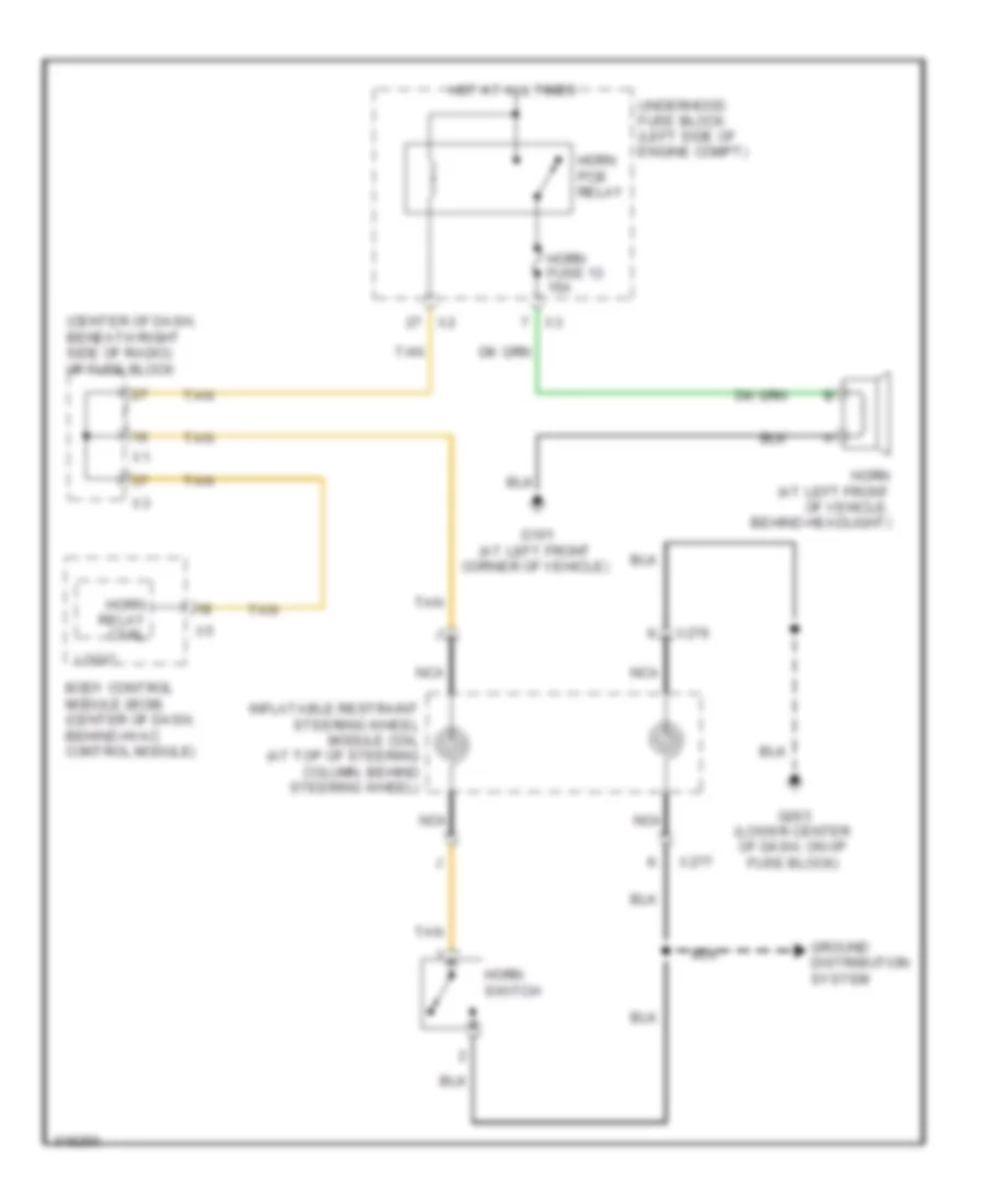
Horn Wiring Diagram for Suzuki XL7 Luxury 2009
List of elements for Horn Wiring Diagram for Suzuki XL7 Luxury 2009:
- (center of dash, beneath right side of radio) i/p fuse block
- Body control module (bcm) (center of dash, behind hvac control module)
- G101 (at left front corner of vehicle)
- G203 (lower center of dash, on i/p fuse block)
- Ground distribution system
- Horn (at left front of vehicle, behind headlight)
- Horn fuse 13 15a
- Horn pcb relay
- Horn relay ctrl
- Horn switch
- Hot at all times
- Inflatable restraint steering wheel module coil (at top of steering column, behind steering wheel)
- Logic
- Nca
- Tan
- Underhood fuse block (left side of engine compt)
- X276
- X277
INSTRUMENT CLUSTER
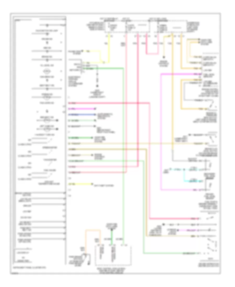
Instrument Cluster Wiring Diagram for Suzuki XL7 Luxury 2009
List of elements for Instrument Cluster Wiring Diagram for Suzuki XL7 Luxury 2009:
- (not used)
- 000000 trip
- Abs ind
- Air bag ind
- Airbag display fuse 25 10a
- Anti-theft system
- Body control module (bcm) (center of dash, behind hvac control module)
- Brake fluid level switch (on master brake cylinder reservoir)
- Brake ind
- Brake warning ind ctrl
- Class 2 (pcm)
- Clstr fuse 18 10a
- Computer data lines system
- Coolant temperature gauge
- Cruise ind
- Dic select menu sw sig
- Dic sw sig
- Driver information center (dic) switch
- Electronic compass module (w/ 8 speaker system)
- Engine control module (ecm) (mounted on top of battery cover)
- Engine controls system
- Engine oil pressure (eop) switch (left side of engine, about starter motor)
- Fog lamps ind
- Fuel gauge
- Fuel level sens sig
- Fuel pump & sender assembly (inside right side of fuel tank)
- G201 (behind right front kick panel)
- G203 (lower center of dash, on i/p fuse block)
- G311 (under right front seat)
- G403 (under right side of luggage compt)
- Gnd
- Ground
- Hi spd gmlan ser data +
- Hi spd gmlan ser data -
- High beam ind
- Hot at all times
- Hot w/ ign 1 main relay 31 energized
- Hot w/ rap relay energized
- I/p fuse block (center of dash, beneath right side of radio)
- Ign
- Ignvol
- Instrument panel cluster (ipc)
- Interior lights system
- Lcd display
- Left turn ind
- Logic
- Low gmlan serial data
- Low ref
- Low ref oil pressure sw sig
- Low spd gmlan serial data
- Malfunction ind lamp
- Network 3
- Oil level ind
- Park brake switch (at base of park brake lever)
- Pass air bag off ind ctrl
- Pass air bag on ind ctrl
- Pass seat belt ind
- Pnk
- Power tops system
- Primary fuel level sensor
- Right turn ind
- S/roof fuse 1 10a
- Seat belt ind
- Secondary fuel level sensor
- Security ind
- Speedometer
- Sw sig park brake
- Tachometer
- Tan
- Underhood fuse block (left side of engine compt)
INTERIOR LIGHTS
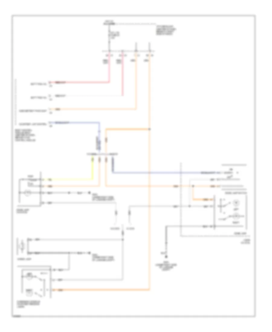
Courtesy Lamps Wiring Diagram for Suzuki XL7 Luxury 2009
List of elements for Courtesy Lamps Wiring Diagram for Suzuki XL7 Luxury 2009:
- Batt pos vol
- Body control module (bcm) (center of dash, behind hvac control module)
- Cargo lamp
- Courtesy lmp control
- Dome lamp
- Dome lamp (w/o dvd)
- Dome lamp switch
- Door
- G403 (under right side of luggage compt)
- Hot at all times
- I/p fuse block (center of dash, beneath right side of radio)
- Inadvertent pwr cont
- Int lts fuse 23 10a
- Left
- Off
- Overhead console courtesy/reading lamps
- Right
- Visor (w/ dvd)
- W/ dvd
- W/o dvd
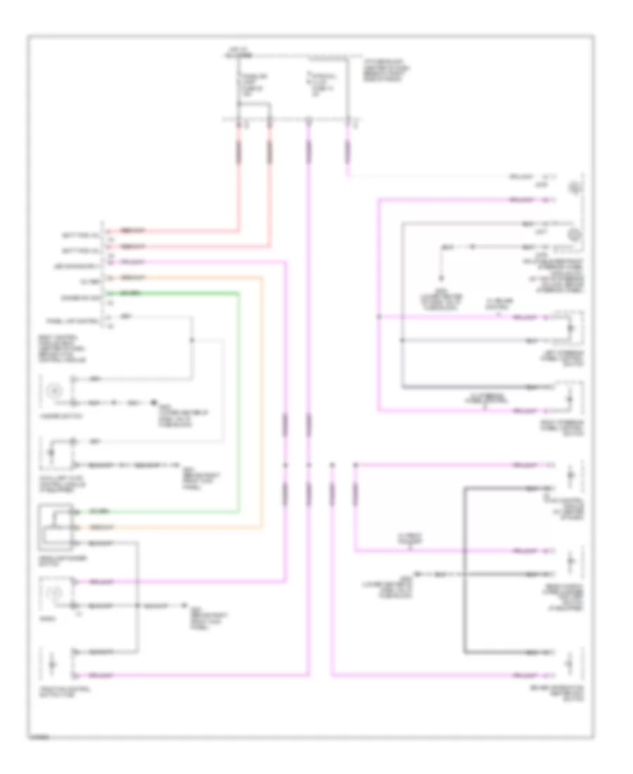
Instrument Illumination Wiring Diagram for Suzuki XL7 Luxury 2009
List of elements for Instrument Illumination Wiring Diagram for Suzuki XL7 Luxury 2009:
- 12v ref
- Auxillary hvac control module (if equipped)
- Batt pos vol
- Body control module (bcm) (center of dash, behind hvac control module)
- Chmsl/dm lamp fuse 22 15a
- Control
- Dimmer sw sig
- Driver information center (dic) switch
- G201 (behind right front kick panel)
- G203 (lower center of dash, on i/p fuse block)
- Hazard switch
- Headlamp dimmer switch
- Hot at all times
- Hvac control module (at center of dash)
- I/p fuse block (center of dash, beneath right side of radio)
- Inflatable restraint steering wheel module coil (at top of steering column, behind steering wheel)
- Led dimming sply
- Left steering wheel control switch
- Panel lmp control
- Radio
- Rear window wiper washer fog lamp switch (if equipped)
- Right steering wheel control switch
- Str/whl/ illum fuse 13 2a
- Traction control switch (tcs)
- W/ cruise
- W/ front fog lamp
- W/ steering wheel control
- X276
- X277
POWER DISTRIBUTION
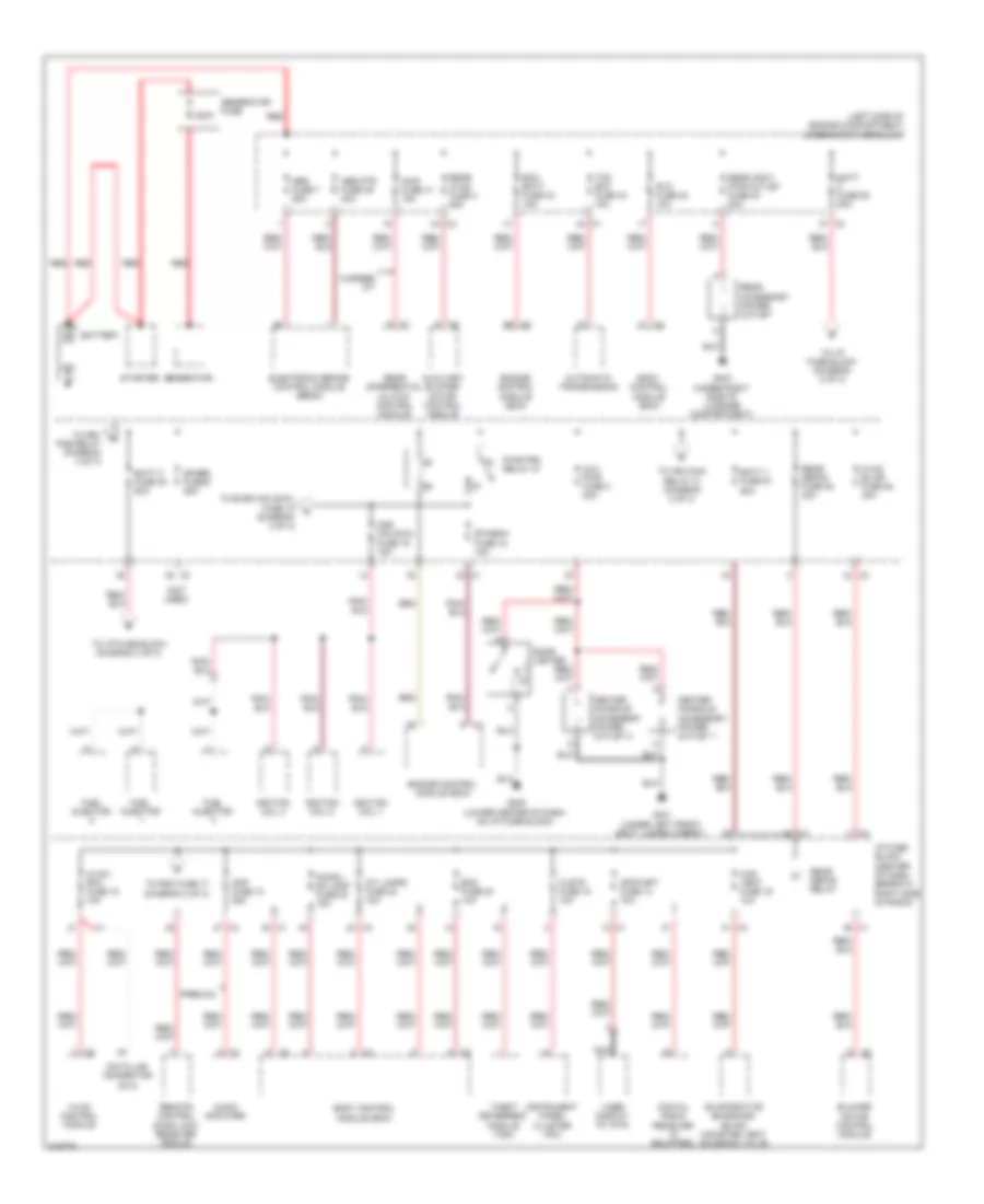
Power Distribution Wiring Diagram (1 of 3) for Suzuki XL7 Luxury 2009
List of elements for Power Distribution Wiring Diagram (1 of 3) for Suzuki XL7 Luxury 2009:
- (left side of engine compartment) underhood fuse block
- (not used)
- 200a
- 6 speed a/t
- Abs fuse 7 25a
- Abs mtr fuse 49 40a
- Amp fuse 12 25a
- Audio amplifier
- Automatic transmission
- Aux pwr fuse 3 20a
- Auxiliary blower motor control module
- Awd fuse 41 15a
- Batt 1 fuse 57 50a
- Batt 3 fuse 30 50a
- Batt fuse 50 50a
- Battery
- Bcm fuse 20 10a
- Blower motor control module
- Body control module (bcm)
- Can vent fuse 16 10a
- Center console accessory power outlet 1
- Center console accessory power outlet 2
- Chmsl/ dm lamp fuse 22 15a
- Cigar lighter
- Clstr fuse 18 10a
- Data link connector (dlc)
- Digital radio receiver (if equipped)
- Ecm batt fuse 33 15a
- Electronic brake control module (ebcm)
- Engine control module (ecm)
- Etc/ecm fuse 16 15a
- Evaporative emissions (evap) canister vent solenoid valve
- Fuel injector
- G203 (lower center of dash, on i/p fuse block)
- G301 (under left front seat, under carpet)
- G403 (under right side of luggage compartment)
- Generator
- Generator fuse
- Hvac blwr fuse 54 40a
- Hvac control module
- Hvac/ rfa fuse 15 10a
- I/p fuse block (center of dash, beneath right side of radio)
- Ignition coil 1
- Ignition coil 3
- Ignition coil 5
- Infotmnt fuse 14 10a
- Instrument panel cluster (ipc)
- Int lamps fuse 23 10a
- Nca
- Odd coils/inj fuse 19 15a
- Premium
- Pwr/trn relay 47
- Rear accessory power outlet
- Rear accy pwr outlet fuse 40 20a
- Rear defog fuse 48 30a
- Rear defog relay
- Rear differential clutch control module
- Rear hvac fuse 4 25a
- Red
- Remote control door lock receiver (rcdlr)
- Rvc fuse 42 10a
- Spare fuse 6 25a
- Starter
- Tcm bat fuse 34 15a
- Theft deterrent module (tdm)
- To drl pcb relay (diagram 3 of 3)
- To even coils/inj fuse 18 (diagram 2 of 3)
- To i/p fuse block (diagram 2 of 3)
- To i/p fuse block (diagram 3 of 3)
- To ign main relay 31 (diagram 2 of 3)
- To rdo fuse 17 (diagram 2 of 3)
- Video display (w/ dvd)
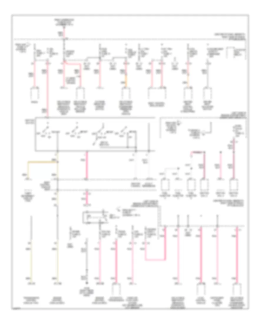
Power Distribution Wiring Diagram (2 of 3) for Suzuki XL7 Luxury 2009
List of elements for Power Distribution Wiring Diagram (2 of 3) for Suzuki XL7 Luxury 2009:
- (center of dash, beneath right side of radio) i/p fuse block
- (left side of engine compartment) underhood fuse block
- (not used)
- 5-volt reference
- Acc
- Air bag disply fuse 25 10a
- Air bag fuse 5 10a
- Aos module fuse 9 10a
- Automatic transmission
- Body control module (bcm)
- Driver seat adjuster switch
- Engine control module (ecm)
- Even coils/ inj fuse 18 15a
- From amp f fuse 12 (diagram 1 of 3)
- From batt 1 fuse 57 (diagram 1 of 3)
- From odd c coils/inj fuse 19 (diagram 1 of 3)
- From underhood fuse block (diagram 1 of 3)
- Fuel injector
- G109 (right rear of cylinder head)
- Heated seat control module (if equipped)
- Htd/ seats fuse 6 20a
- Hvac control module
- Ign 1 relay 31
- Ign sw fuse 19 2a
- Ignition 0 signal
- Ignition coil 2
- Ignition coil 4
- Ignition coil 6
- Ignition switch
- Inflatable restraint passenger air bag on/off indicator
- Inflatable restraint passenger presence (pps) module
- Inflatable restraint sensing & diagnostic module (sdm)
- Inflatable restraint vehicle rollover sensor
- Instrument panel cluster (ipc)
- Key-in switch
- Liftgate pcb relay
- Lt trn/ sig fuse 7 15a
- Maf fuse 24 10a
- Mass air flow (maf)/ intake air temperature (iat) sensor
- Off
- Outside rearview mirror switch
- Pcm ign fuse 22 10a
- Pnk
- Power seat circuit breaker 25a
- Pwr mirs fuse 10 2a
- Radio
- Rdo fuse 17 25a
- Rt trn/ sig fuse 11 15a
- Spare fuse 21 15a
- Start
- Theft deterrent module (tdm)
- To emiso 2 fuse 20 (diagram 3 of 3)
- Trans fuse 23 10a
- Transmission control module (tcm)
- W/ head curtain air bag
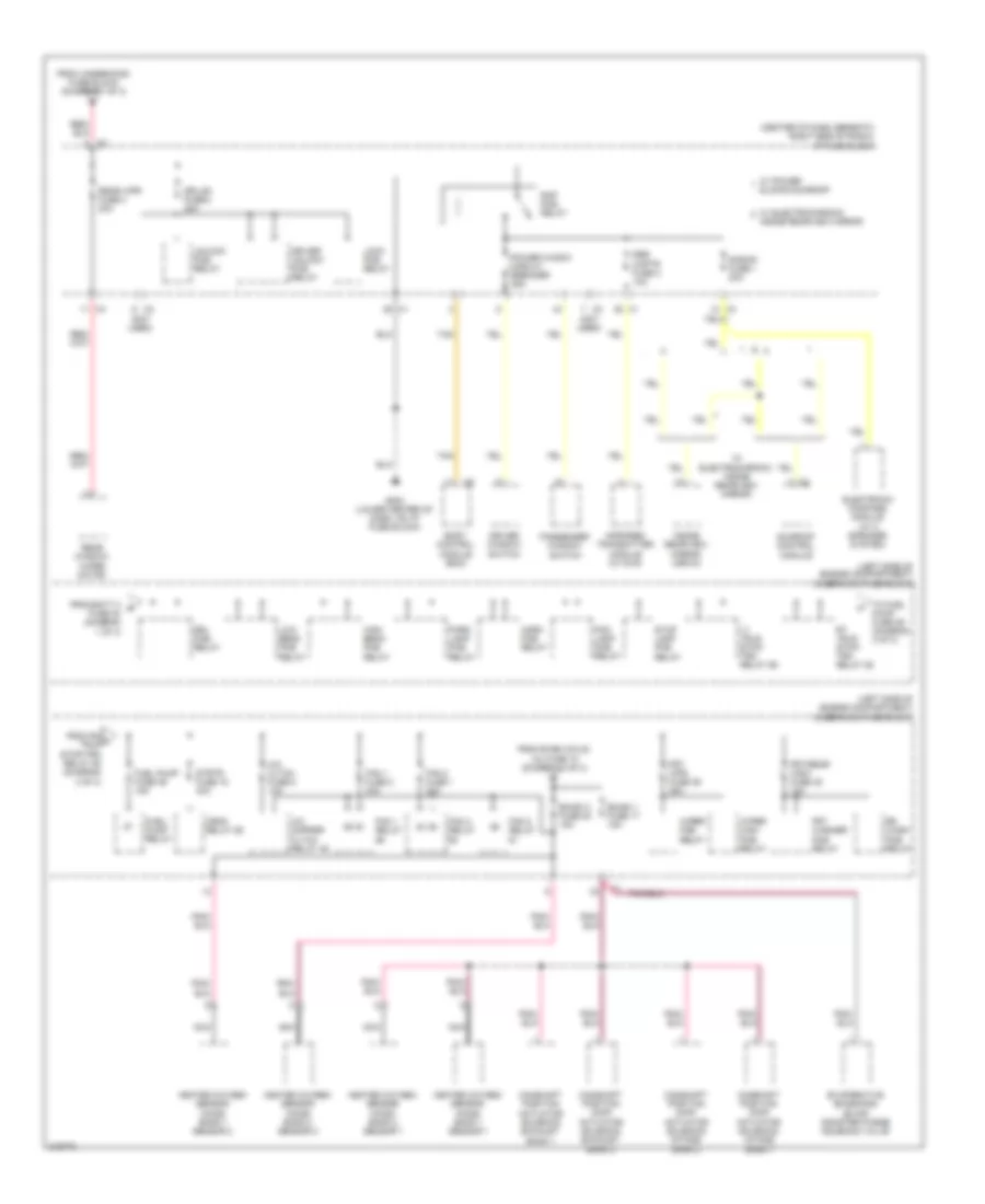
Power Distribution Wiring Diagram (3 of 3) for Suzuki XL7 Luxury 2009
List of elements for Power Distribution Wiring Diagram (3 of 3) for Suzuki XL7 Luxury 2009:
- (center of dash, beneath right side of radio) i/p fuse block
- (left side of engine compartment) underhood fuse block
- (not used)
- A/c cltch fuse 8 10a
- A/c cmprsr cltch relay 46
- Body control module (bcm)
- Camshaft position (cmp) actuator solenoid exhaust bank 2
- Camshaft position (cmp) actuator solenoid intake bank 1
- Camshaft position (cmp) actuator solenoid intake bank 2
- Camshaft position actuator solenoid exhaust bank 1
- Crnk relay 55
- Dr/lck fuse 8 25a
- Driver unlock pcb relay
- Driver window switch
- Drl pcb relay
- Electronic compass module (w/ 8 speaker system)
- Emiso 1 fuse 17 15a
- Emiso 2 fuse 20 15a
- Evaporative emissions (evap) canister purge solenoid valve
- Fan 1 fuse 2 30a
- Fan 1 relay
- Fan 2 fuse 1 30a
- Fan 2 relay
- Fan 3 relay
- Fog lamp pcb relay
- From batt 3 b fuse 30 (diagram 1 of 3)
- From even coils/ inj fuse 18 (diagram 2 of 3)
- From rh h trlr stop/trn relay 58 (diagram 3 of 3)
- From underhood fuse block (diagram 1 of 3)
- Frt washer pcb relay
- Frt wpr fuse 36 25a
- Frt/rear wsw fuse 45 10a
- Fuel pump fuse 39 15a
- Fuel/ pump relay
- G203 (lower center of dash, on i/p fuse block)
- Heated oxygen sensor (ho2s) bank 1 sensor 1
- Heated oxygen sensor (ho2s) bank 1 sensor 2
- Heated oxygen sensor (ho2s) bank 2 sensor 1
- Heated oxygen sensor (ho2s) bank 2 sensor 2
- High beam pcb relay
- Horn pcb relay
- Infrared transmitter module (w/ dvd)
- Inside rearview mirror
- Inside rearview mirror (isrvm)
- Lock pcb relay
- Low beam pcb relay
- Lt trlr stop/ trn relay 59
- Nca
- Park lamp pcb relay
- Passenger window switch
- Power windw circuit breaker 25a
- Rap pcb relay
- Rear window wiper motor
- Rear wpr fuse 3 20a
- Rr wash pcb relay
- Rse captr fuse 2 10a
- Rt trlr stop/ trn relay 58
- S/roof fuse 1 20a
- Stop lamp pcb relay
- Strtr fuse 15 40a
- Sunroof control module
- Tan
- To fuel pump fuse 39 (diagram 3 of 3)
- Unlock pcb relay
- W/ electrochromic
- W/ electrochromic inside rearview mirror
- W/ power sliding sunroof
- Wiper high pcb relay
- Wiper pcb relay
POWER DOOR LOCKS
Power Door Locks Wiring Diagram for Suzuki XL7 Luxury 2009
List of elements for Power Door Locks Wiring Diagram for Suzuki XL7 Luxury 2009:
- (not used)
- (under right front seat) g311
- Bat pos volt
- Body control module (bcm) (center of dash, behind hvac control module)
- Clstr fuse 18 10a
- Coax
- Computer data lines system
- Dr/lck fuse 8 25a
- Driver door latch
- Driver door lock switch
- Driver unlock pcb relay
- Drv dr ajar sw sig
- Drv dr lk sw sig
- Drv dr unlk sw sig
- Drv unlk rly ctrl
- G101 (at left front corner of vehicle)
- G203 (lower center of dash, on i/p fuse block)
- G311 (under right front seat)
- G401 (under left side of luggage compt)
- Gmlan ser data
- Ground
- Hood ajar sw sig
- Hood ajar switch
- Hood closed sw sig
- Horn rly ctrl
- Horns system
- Hot at all times
- Hvac/rfa fuse 15 10a
- I/p fuse block (center of dash, beneath right side of radio)
- Instrument panel cluster (ipc)
- Keyless entry antenna
- Left rear door latch
- Liftgate ajar sw sig
- Liftgate latch
- Lock pcb relay
- Lock rly ctrl
- Nca
- Pass dr ajar sw sig
- Pass dr lk sw ctrl
- Pass dr unlk sw ctrl
- Passenger door latch
- Passenger door lock switch
- Remote control door lock receiver (rcdlr) (on right "c" pillar)
- Right rear door latch
- Security ind
- Security ind ctrl
- Ser data
- Tan
- Underhood fuse block (left side of engine compt)
- Unlock pcb relay
- Unlock rly ctrl
- Wiper/ washer system
POWER MIRRORS
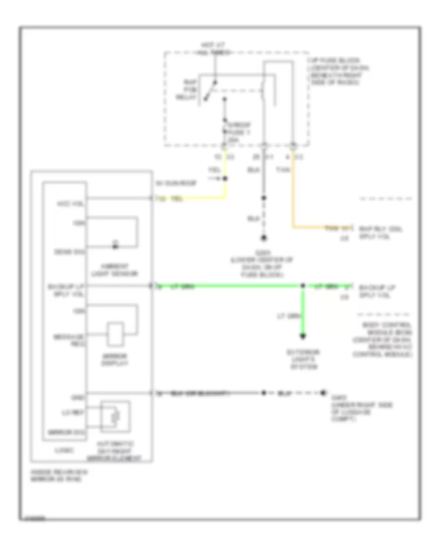
Automatic Day/Night Mirror Wiring Diagram for Suzuki XL7 Luxury 2009
List of elements for Automatic Day/Night Mirror Wiring Diagram for Suzuki XL7 Luxury 2009:
- Acc vol
- Ambient light sensor
- Automatic day/night mirror element
- Backup lp sply vol
- Body control module (bcm) (center of dash, behind hvac control module)
- Exterior lights system
- G203 (lower center of dash, on i/p fuse block)
- G403 (under right side of luggage compt)
- Gnd
- Hot at all times
- I/p fuse block (center of dash, beneath right side of radio)
- Ign
- Inside rearview mirror (is rvm)
- Lo ref
- Logic
- Message req
- Mirror display
- Mirror sig
- Rap pcb relay
- Rap rly coil sply vol
- S/roof fuse 1 20a
- Sens sig
- Tan
- W/ sun roof
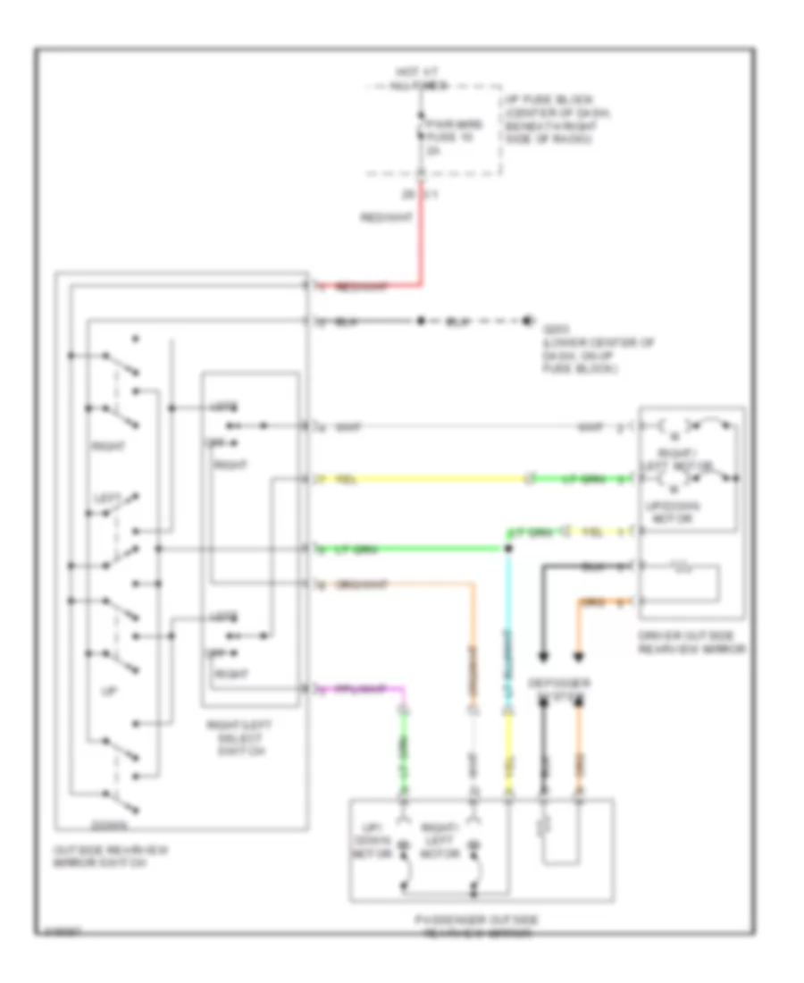
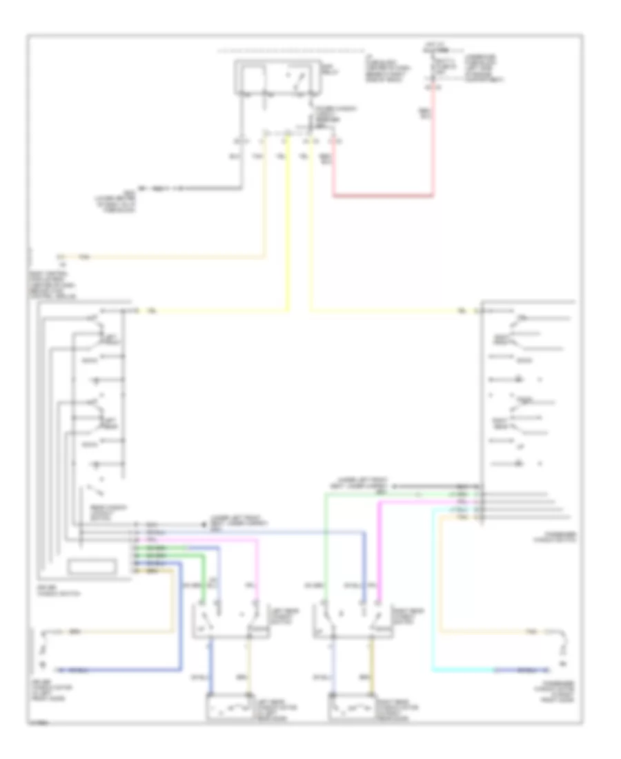
Power Mirror Wiring Diagram, with Heated Mirrors for Suzuki XL7 Luxury 2009
List of elements for Power Mirror Wiring Diagram, with Heated Mirrors for Suzuki XL7 Luxury 2009:
- Defogger system
- Down
- Driver outside rearview mirror
- G203 (lower center of dash, on i/p fuse block)
- Hot at all times
- I/p fuse block (center of dash, beneath right side of radio)
- Left
- Off
- Outside rearview mirror switch
- Passenger outside rearview mirror
- Pwr mirs fuse 10 2a
- Right
- Right/ left motor
- Right/left select switch
- Up/ down motor
- Up/down motor
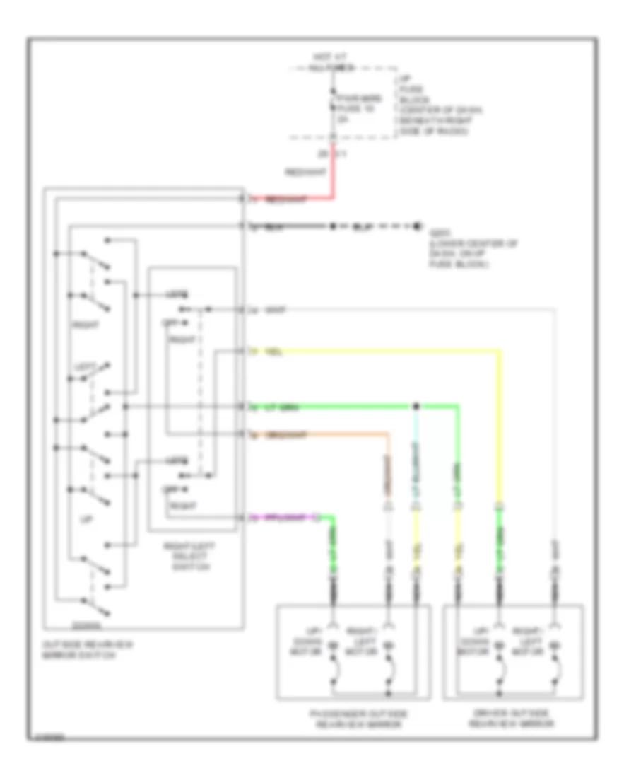
Power Mirror Wiring Diagram, without Heated Mirrors for Suzuki XL7 Luxury 2009
List of elements for Power Mirror Wiring Diagram, without Heated Mirrors for Suzuki XL7 Luxury 2009:
- Down
- Driver outside rearview mirror
- G203 (lower center of dash, on i/p fuse block)
- Hot at all times
- I/p fuse block (center of dash, beneath right side of radio)
- Left
- Motor
- Nca
- Off
- Outside rearview mirror switch
- Passenger outside rearview mirror
- Pwr mirs fuse 10 2a
- Right
- Right/ left motor
- Right/left select switch
- Up/ down m
- Up/ down motor
POWER SEATS
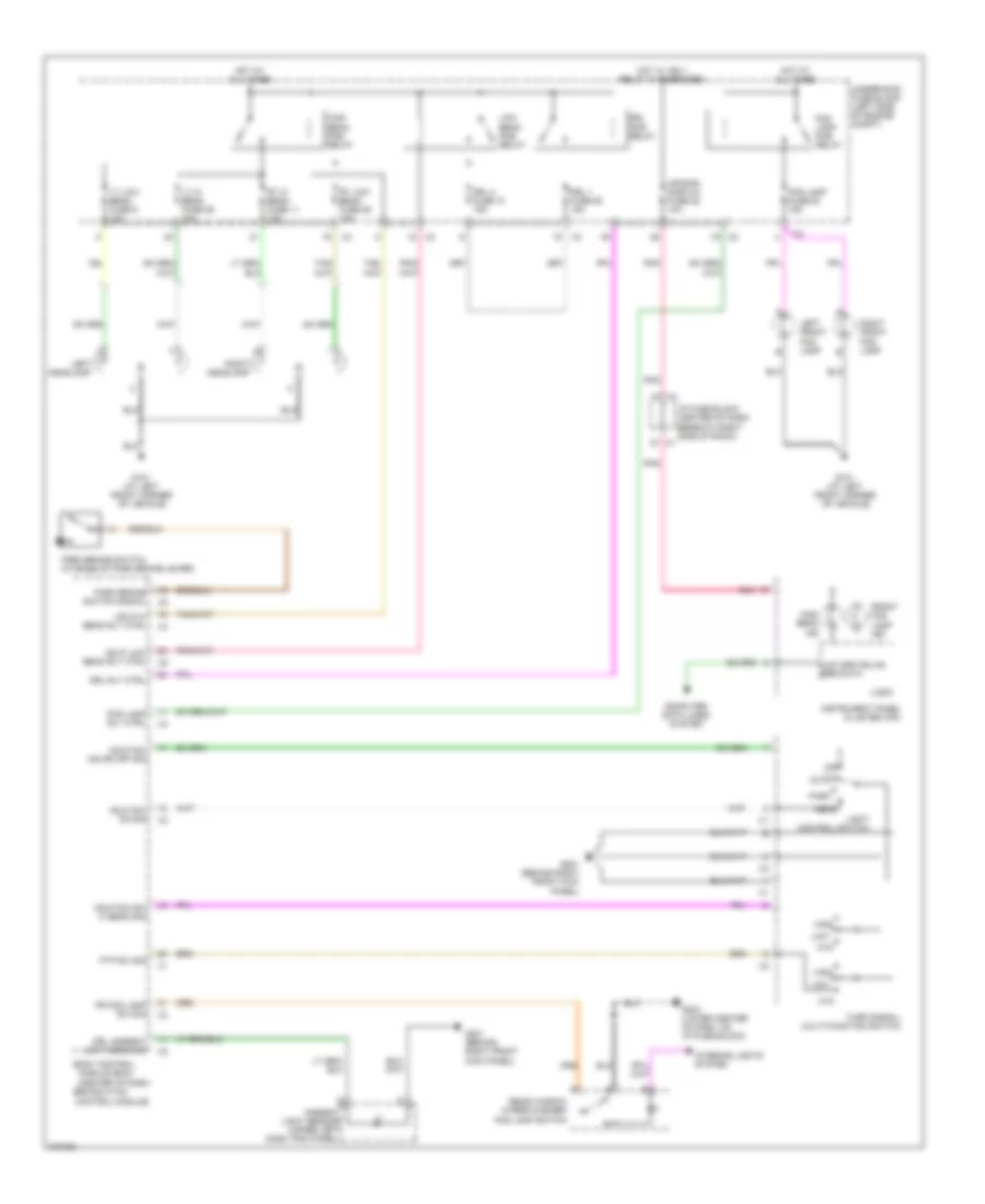
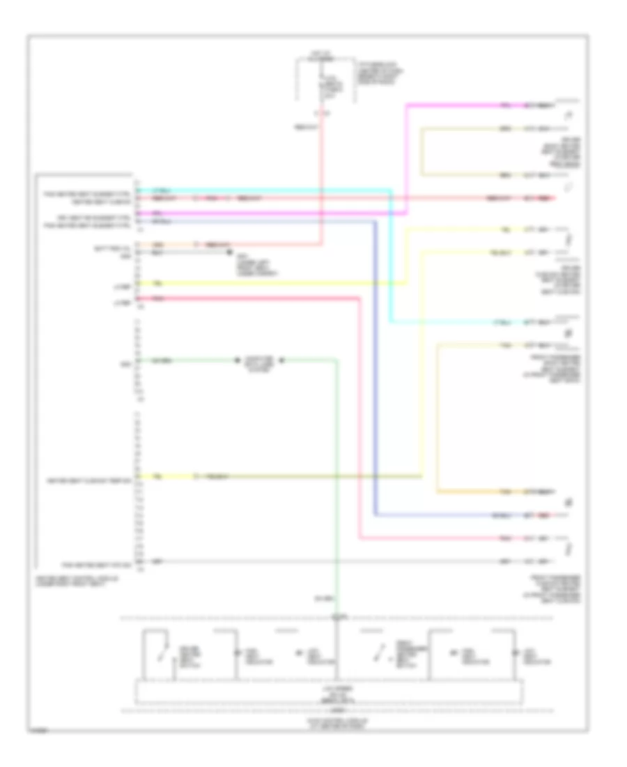
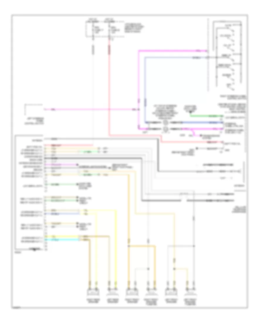
Climate Control Seats Wiring Diagram for Suzuki XL7 Luxury 2009
List of elements for Climate Control Seats Wiring Diagram for Suzuki XL7 Luxury 2009:
- A x3
- Batt pos vol
- Computer data lines system
- Driver back heated seat element (in driver seat back)
- Driver cushion heated seat element (in driver seat cushion)
- Driver heated seat switch
- Drv seat bk element ctrl
- Front passenger back heated seat element (in front passenger seat back)
- Front passenger cushion heated seat element (in front passenger seat cushion)
- Front passenger heated seat switch
- G301 (under left front seat, under carpet)
- Gnd
- Heated seat control module (under right front seat)
- Heated seat cushion
- Heated seat cushion temp sig
- High heat indicator
- Hot at all times
- Htd/ seats fuse 6 20a
- Hvac control module (at center of dash)
- I/p fuse block (center of dash, beneath right side of radio)
- Lo ref
- Logic
- Low heat indicator
- Low speed gmlan serial data
- Pas heated seat element ctrl
- Pas heated seat ntc sig
- Pnk
- Red
- Tan
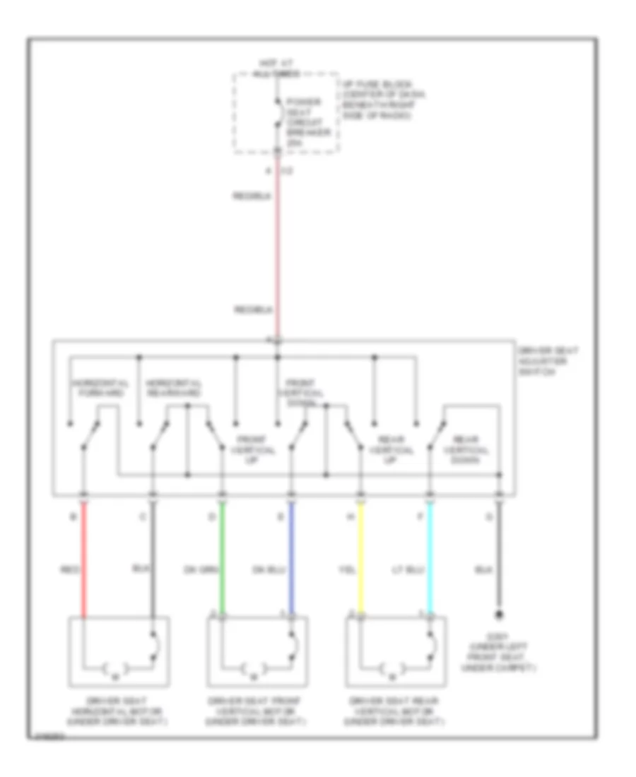
Driver Seat Wiring Diagram for Suzuki XL7 Luxury 2009
List of elements for Driver Seat Wiring Diagram for Suzuki XL7 Luxury 2009:
- (under left front seat,
- Down
- Driver seat adjuster switch
- Driver seat front vertical motor (under driver seat)
- Driver seat horizontal motor (under driver seat)
- Driver seat rear vertical motor (under driver seat)
- Front
- Front vertical down
- G301
- Horizontal forward
- Horizontal rearward
- Hot at all times
- I/p fuse block (center of dash, beneath right side of radio)
- Power seat circuit breaker 25a
- Rear
- Red
- Under carpet)
- Vertical
POWER TOP/SUNROOF
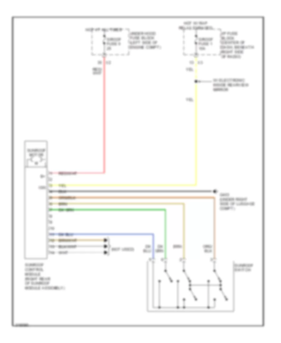
Power Top/Sunroof Wiring Diagram for Suzuki XL7 Luxury 2009
List of elements for Power Top/Sunroof Wiring Diagram for Suzuki XL7 Luxury 2009:
- (not used)
- G403 (under right side of luggage compt)
- Hot at all times
- Hot w/ rap relay enraged
- I/p fuse block (center of dash, beneath right side of radio)
- Ign
- S/roof fuse 1 10a
- S/roof fuse 6
- Sunroof control module (right rear of sunroof module assembly)
- Sunroof motor
- Sunroof switch
- Under hood fuse block (left side of engine compt)
- W/ electronic inside rearview mirror
POWER WINDOWS
Power Windows Wiring Diagram for Suzuki XL7 Luxury 2009
List of elements for Power Windows Wiring Diagram for Suzuki XL7 Luxury 2009:
- (under left front seat, under carpet) g301
- Batt 3 fuse 30 50a
- Body control module (bcm) (center of dash, behind hvac control module)
- Down
- Driver window motor (in left front door)
- Driver window switch
- G203 (lower center of dash, on i/p fuse block)
- Hot at all times
- I/p fuse block (center of dash, beneath right side of radio)
- Left front
- Left rear
- Left rear window motor (in left rear door)
- Left rear window switch
- Passenger window motor (in right front door)
- Passenger window switch
- Power window circuit breaker 25a
- Rap relay
- Rear window lockout switch
- Right front
- Right rear
- Right rear window motor (in right rear door)
- Right rear window switch
- Tan
- Underhood fuse block (left side of engine compartment)
RADIO
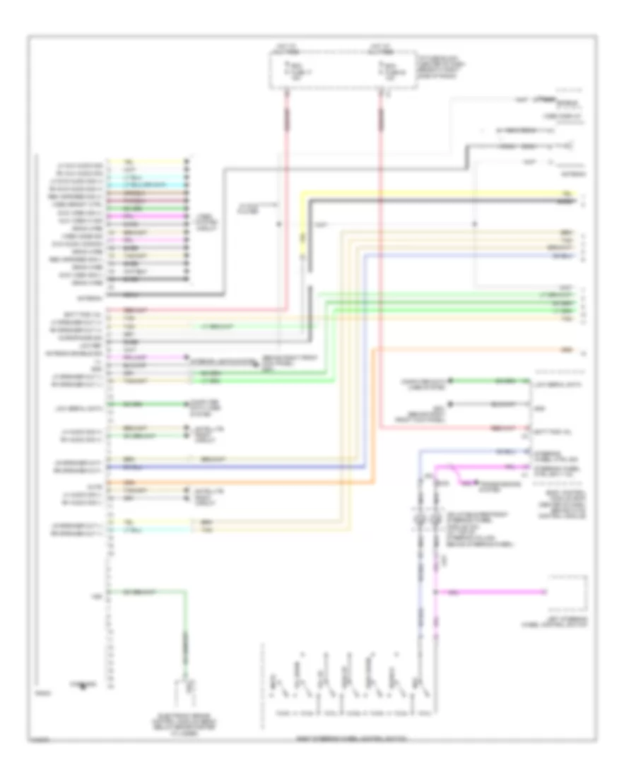
Radio Wiring Diagram, Base for Suzuki XL7 Luxury 2009
List of elements for Radio Wiring Diagram, Base for Suzuki XL7 Luxury 2009:
- (at top of steering column, behind steering wheel) inflatable restraint steering wheel module coil
- (behind right front kick panel) g201
- (center of dash, behind hvac control module) body control module (bcm)
- Antenna
- Antenna enable sig
- Bare
- Batt pos vol
- Bcm fuse 20 10a
- Case gnd
- Cellular telephone microphone
- Coax
- Computer data lines system
- Drain wire
- G201 (behind right front kick panel)
- Gnd
- Ground
- Hot at all times
- I/p fuse block (center of dash, beneath right side of radio)
- Info
- Interior lights system
- Led dimming sdly
- Left front speaker
- Left front speaker tweeter
- Left rear speaker
- Left steering wheel control switch
- Lf speaker out (+)
- Lf speaker out (-)
- Low serial data
- Lr speaker out (+)
- Lr speaker out (-)
- Microphone sig
- Mute
- Nca
- Radio
- Rdo fuse 17 15a
- Rem lt audio sig (+)
- Rem lt audio sig (-)
- Rem rt audio sig (+)
- Rem rt audio sig (-)
- Rf speaker out (+)
- Rf speaker out (-)
- Right front speaker
- Right front speaker tweeter
- Right rear speaker
- Right steering wheel control switch
- Rr speaker out (+)
- Rr speaker out (-)
- Satellite radio circuit
- Seek down
- Seek up
- Source
- Steering wheel ctrl sig
- Steering wheel ctrl sply vol
- Tan
- Transmissions system
- Vol down
- Vol up
- X276
- X277
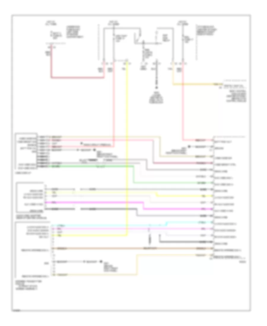
Radio Wiring Diagram, Premium (1 of 2) for Suzuki XL7 Luxury 2009
List of elements for Radio Wiring Diagram, Premium (1 of 2) for Suzuki XL7 Luxury 2009:
- (behind right front kick panel) g201
- Antenna
- Antenna enable sig
- Aux video hi sig
- Bare
- Batt pos vol
- Bcm fuse 20 10a
- Body control module (bcm) (center of dash, behind hvac control module)
- Case gnd
- Coax
- Computer data lines system
- Drain wire
- Dvd audio common
- Dvd video sig (+)
- Dvd video sig (-)
- Electronic brake control module (ebcm) (below brake master cylinder)
- G201 (behind right front kick panel)
- Gnd
- Hot at all times
- I/p fuse block (center of dash, beneath right side of radio)
- Ill
- Inflatable restraint steering wheel module coil (at top of steering column, behind steering wheel)
- Info
- Interior lights system
- Left steering wheel control switch
- Lf speaker out (+)
- Lf speaker out (-)
- Lh audio sig (+)
- Lh audio sig (-)
- Lh aux audio sig
- Lh dvd audio sig (+)
- Low ref
- Low serial data
- Lr speaker out (-)
- Lr speaker out+
- Microphone sig
- Mute
- Nca
- Nca enable
- Radio
- Rdo fuse 17 15a
- Rem infrared sig (+)
- Rem infrared sig (-)
- Rf speaker out (+)
- Rf speaker out (-)
- Rh audio sig (+)
- Rh audio sig (-)
- Rh aux audio sig
- Rh dvd audio sig (+)
- Right steering wheel control switch
- Rr speaker out (-)
- Rr speaker out+
- Satellite radio circuit
- Seek down
- Seek up
- Source
- Steering wheel ctrl sig
- Steering wheel ctrl sply vol
- Tan
- Transmissions system
- Video bright ctrl
- Video display
- Video mode sig
- Video system circuit
- Vol down
- Vol up
- Vss
- W/ dvd player
- X276 c
- X277
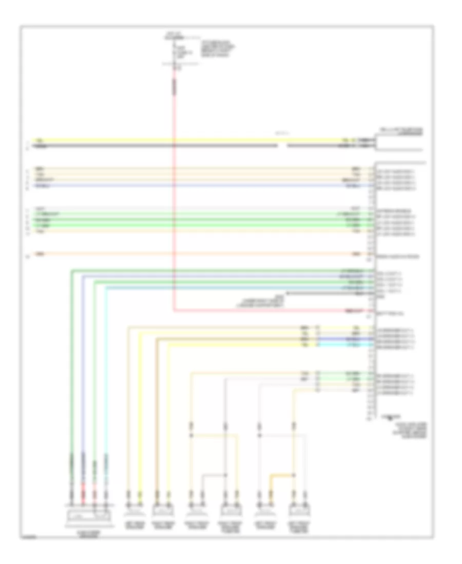
Radio Wiring Diagram, Premium (2 of 2) for Suzuki XL7 Luxury 2009
List of elements for Radio Wiring Diagram, Premium (2 of 2) for Suzuki XL7 Luxury 2009:
- Amp fuse 12 25a
- Antenna enable
- Audio amplifier (in right rear quarter, behind subwoofer)
- Bare
- Batt pos vol
- Case gnd
- Cellular telephone microphone
- Coil 1 out (+)
- Coil 1 out (-)
- Coil 2 out (+)
- Coil 2 out (-)
- G403 (under right side of luggage compartment)
- Gnd
- Hot at all times
- I/p fuse block (center of dash, beneath right side of radio)
- Left front speaker
- Left front speaker tweeter
- Left rear speaker
- Lf low audio sig (+)
- Lf low audio sig (-)
- Lf speaker out (+)
- Lf speaker out (-)
- Lr low audio sig (+)
- Lr low audio sig (-)
- Lr speaker out (+)
- Lr speaker out (-)
- Nca
- Radio audio mute sig
- Red
- Rf low audio sig (+)
- Rf low audio sig (-)
- Rf speaker out (+)
- Rf speaker out (-)
- Right front speaker
- Right front speaker tweeter
- Right rear speaker
- Rr low audio sig (+)
- Rr low audio sig (-)
- Rr speaker out (+)
- Rr speaker out (-)
- Subwoofer speaker
- Tan
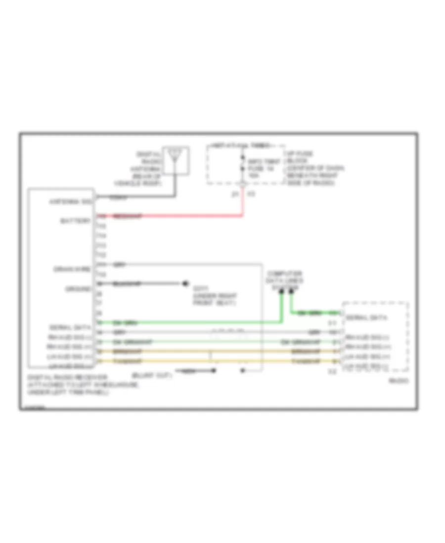
Satellite Radio Wiring Diagram for Suzuki XL7 Luxury 2009
List of elements for Satellite Radio Wiring Diagram for Suzuki XL7 Luxury 2009:
- Antenna sig
- Battery
- Coax
- Computer data lines system
- Digital radio antenna (rear of vehicle roof)
- Digital radio receiver (attached to left wheelhouse, under left trim panel)
- Drain wire
- G311 (under right front seat)
- Ground
- Hot at all times
- I/p fuse block (center of dash, beneath right side of radio)
- Info tmnt fuse 14 10a
- Lh aud sig (+)
- Lh aud sig (-)
- Nca
- Radio
- Rh aud sig (+)
- Rh aud sig (-)
- Serial data
Video System Wiring Diagram for Suzuki XL7 Luxury 2009
List of elements for Video System Wiring Diagram for Suzuki XL7 Luxury 2009:
- (in front of dvd screen assembly)
- (not used)
- Audio/video adapter (rear of center console)
- Aux video hi sig
- Bare
- Batt 3 fuse 30 50a
- Batt pos vol
- Batt pos volt
- Body control module (bcm) (center of dash, behind hvac control module)
- Drain wire
- Dvd audio common
- Dvd video sig (+)
- Dvd video sig (-)
- Dvd video sig(+)
- Dvd video sig(-)
- Enable
- G201 (behind right front kick panel)
- G203 (lower center of dash, on i/p fuse block)
- Gnd
- Ground
- Hot at all times
- I/p fuse block (center of dash, beneath right side of radio)
- Ign volt
- Info tmnt fuse 14 10a
- Infrared transmitter
- Lh aux audio sig
- Lh dvd audio sig (+)
- Module
- Nca
- Radio
- Radio circuit (premium)
- Rap pcb relay
- Rap rly sup vol
- Rdo fuse 17 15a
- Remote infrared sig (+)
- Remote infrared sig (-)
- Remote infrared sig (-) x3
- Rh aux audio sig
- Rh dvd audio sig (+)
- Rh dvd audio sig(+)
- Rse captr fuse 2 10a
- Tan
- Underhood fuse block (left side of engine compartment)
- Video bright ctrl
- Video bright sig
- Video display
- Video mode sig
SHIFT INTERLOCK
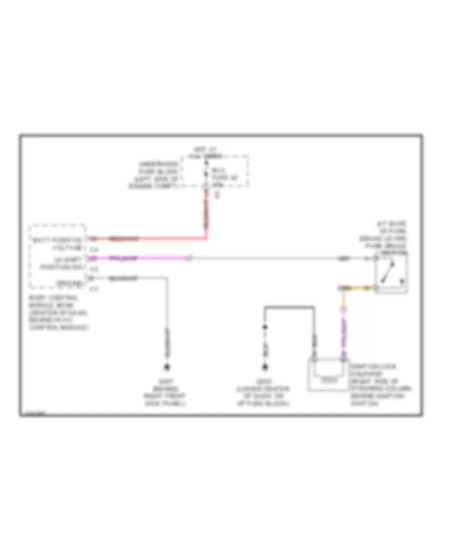
Ignition Lock Solenoid Wiring Diagram for Suzuki XL7 Luxury 2009
List of elements for Ignition Lock Solenoid Wiring Diagram for Suzuki XL7 Luxury 2009:
- (at base of park brake lever) park brake switch
- Batt positive voltage x4
- Body control module (bcm) (center of dash, behind hvac control module)
- G201 (behind right front kick panel)
- G203 (lower center of dash, on i/p fuse block)
- Ground
- Hot at all times
- Ignition lock solenoid (right side of steering column, behind ignition switch)
- Lk shift position sig x2
- Rvc fuse 42 10a
- Underhood fuse block (left side of engine compt)
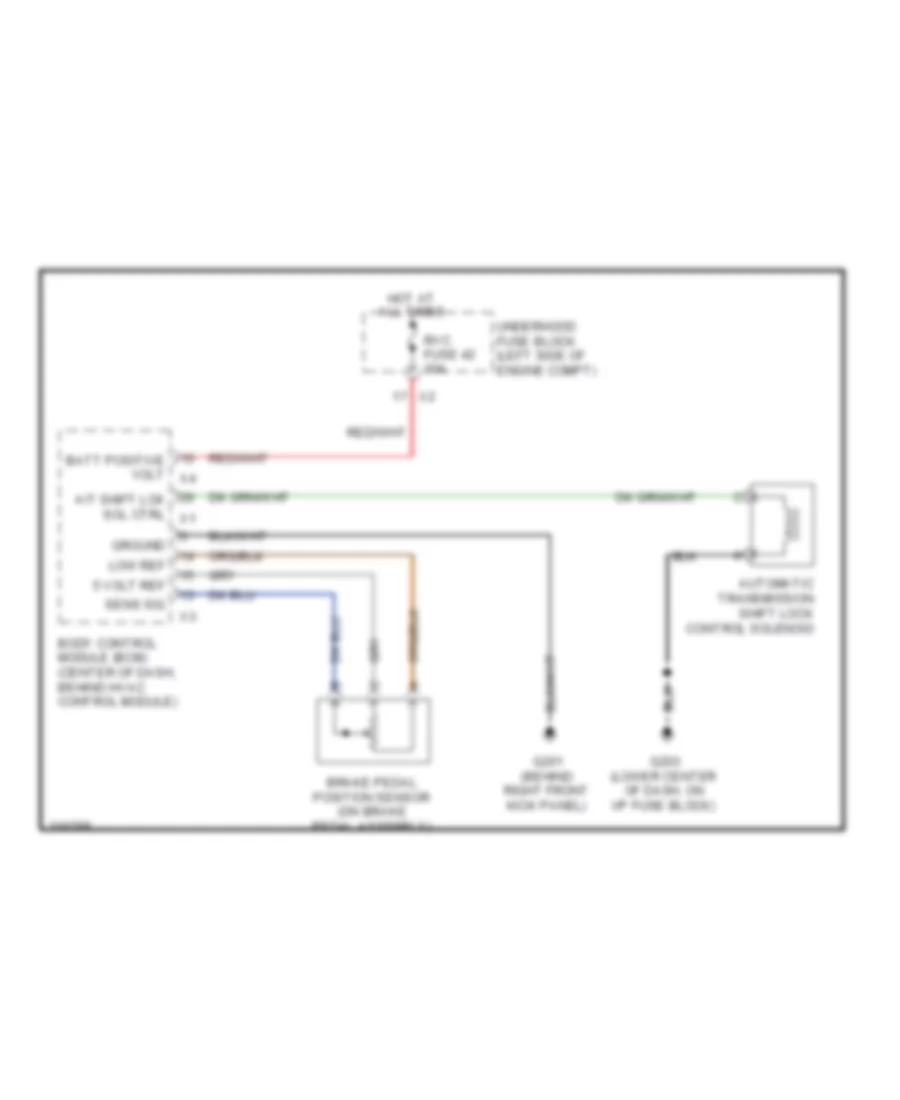
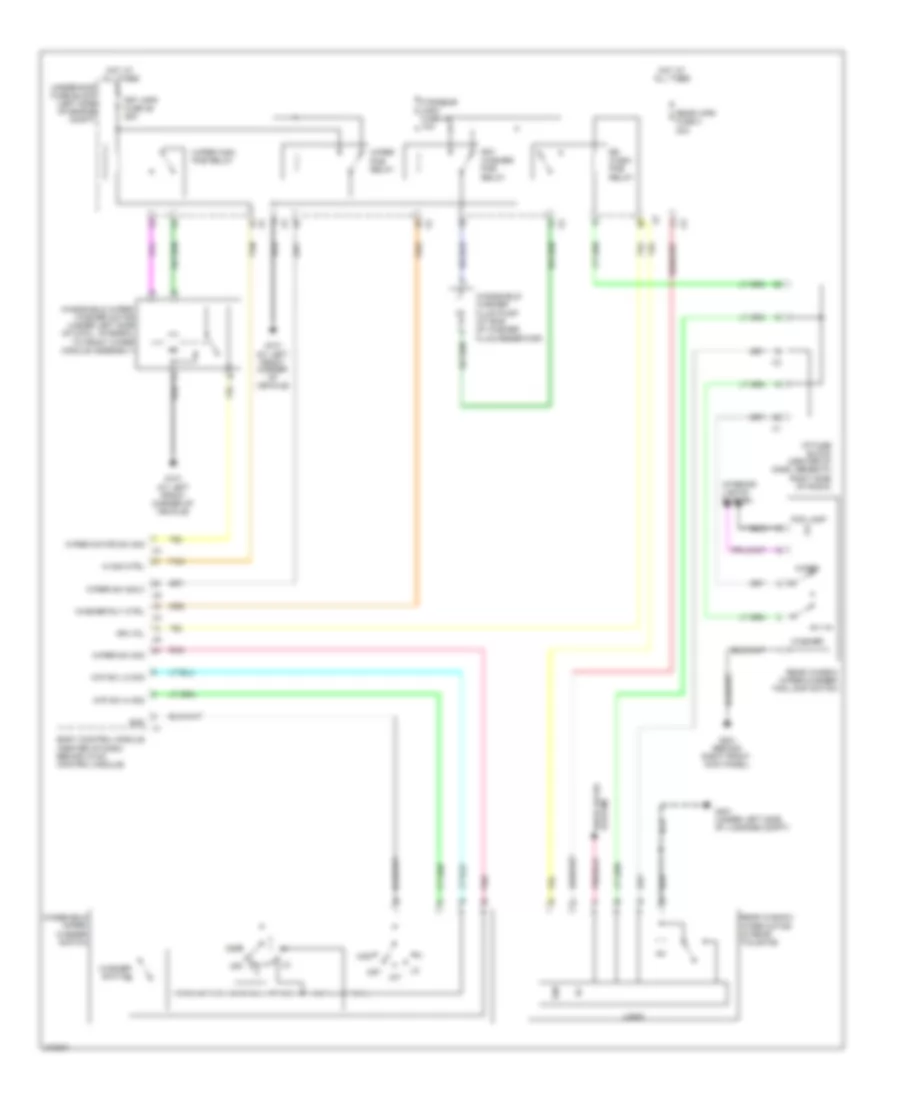
Shift Interlock Wiring Diagram for Suzuki XL7 Luxury 2009
List of elements for Shift Interlock Wiring Diagram for Suzuki XL7 Luxury 2009:
- 5 volt ref
- A/t shift lck sol ctrl x1
- Automatic transmission shift lock control solenoid
- Batt positive volt x4
- Body control module (bcm) (center of dash, behind hvac control module)
- Brake pedal position sensor (on brake pedal assembly)
- G201 (behind right front kick panel)
- G203 (lower center of dash, on i/p fuse block)
- Ground
- Hot at all times
- Low ref
- Rvc fuse 42 10a
- Sens sig
- Underhood fuse block (left side of engine compt)
STARTING/CHARGING
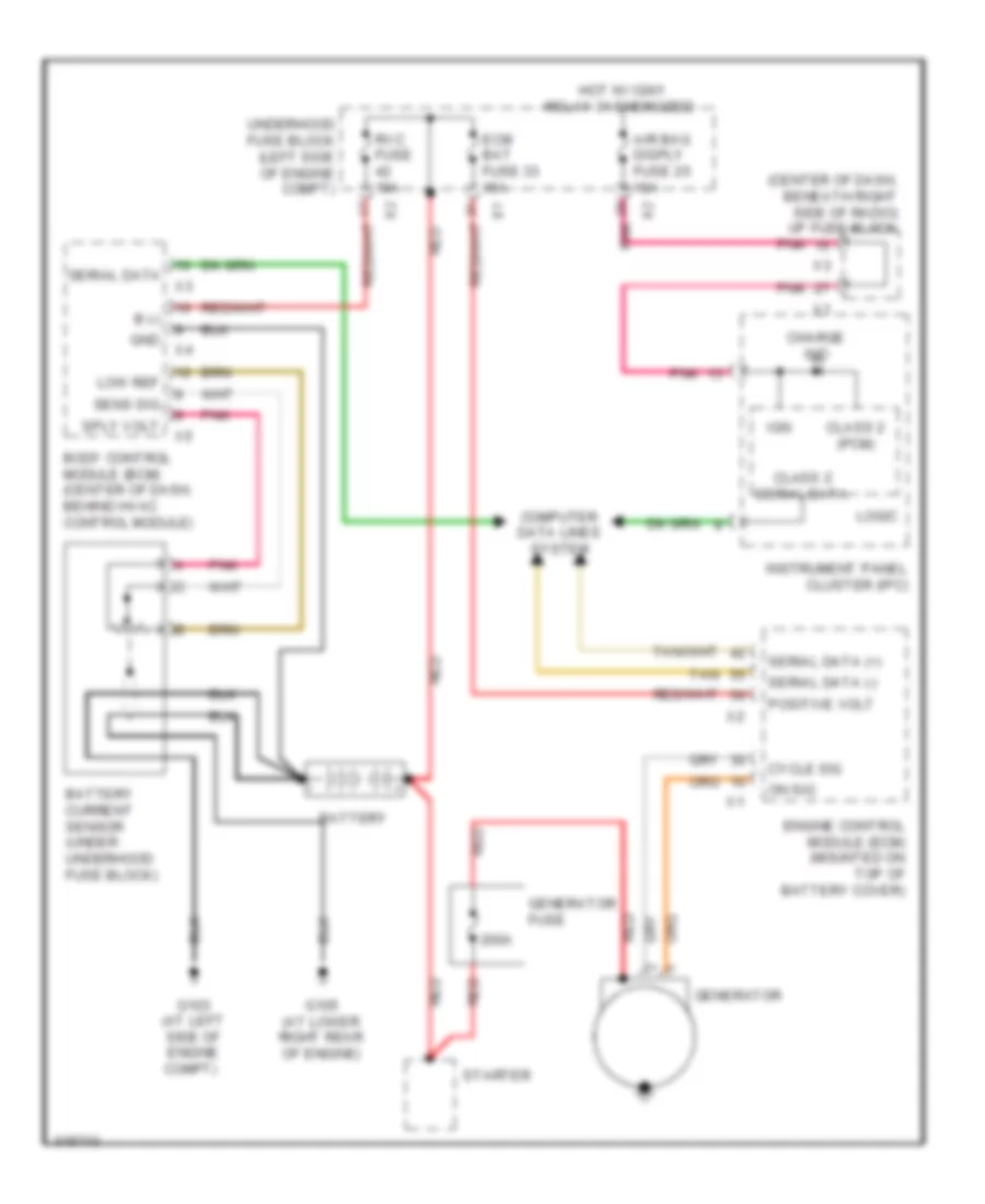
Charging Wiring Diagram for Suzuki XL7 Luxury 2009
List of elements for Charging Wiring Diagram for Suzuki XL7 Luxury 2009:
- (center of dash, beneath right side of radio) i/p fuse block
- 200a
- Air bag disply fuse 25 10a
- B (-)
- Battery
- Battery current sensor (under underhood fuse block)
- Body control module (bcm) (center of dash, behind hvac control module)
- Charge ind
- Class 2 (pcm)
- Class 2 serial data
- Computer data lines system
- Cycle sig
- Ecm bat fuse 33 15a
- Engine control module (ecm) (mounted on top of battery cover)
- G103 (at left side of engine compt)
- G105 (at lower right rear of engine)
- Generator
- Generator fuse
- Gnd
- Hot w/ ign1 relay 31 energized
- Ign
- Instrument panel cluster (ipc)
- Logic
- Low ref
- On sig
- Pnk
- Positive volt
- Red
- Rvc fuse 10a
- Sens sig
- Serial data
- Serial data (+)
- Serial data (-)
- Sply volt
- Starter
- Tan
- Underhood fuse block (left side of engine compt)
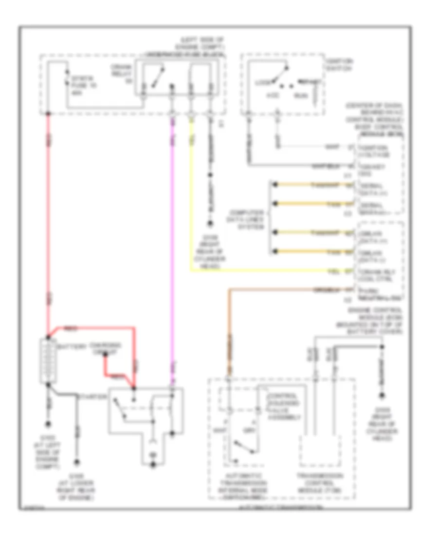
Starting Wiring Diagram for Suzuki XL7 Luxury 2009
List of elements for Starting Wiring Diagram for Suzuki XL7 Luxury 2009:
- (center of dash, behind hvac control module) body control module (bcm)
- (left side of engine compt) underhood fuse block
- Acc
- Automatic transmission
- Automatic transmission internal mode switch (ims)
- Battery
- Charging circuit
- Computer data lines system
- Control solenoid valve assembly
- Crank relay
- Crank rly coil ctrl
- Engine control module (ecm) (mounted on top of battery cover)
- G103 (at left side of engine compt)
- G105 (at lower right rear of engine)
- G109 (right rear of cylinder head)
- Gmlan data (+)
- Gmlan data (-)
- Ign key sig
- Ignition switch
- Ignition voltage
- Lock
- Park/ neutral sig
- Red
- Run
- Serial data (+)
- Serial data (-)
- Start
- Starter
- Strtr fuse 15 40a
- Tan
- Transmission control module (tcm)
SUPPLEMENTAL RESTRAINTS
Supplemental Restraints Wiring Diagram (1 of 2) for Suzuki XL7 Luxury 2009
List of elements for Supplemental Restraints Wiring Diagram (1 of 2) for Suzuki XL7 Luxury 2009:
- (under rear of center console) inflatable restraint sensing & diagnostic module (sdm)
- (under right front seat) g311
- 10a
- Air bag disply fuse 25 10a
- Air bag fuse 5 10a
- Air bag ind
- Aos mdl fuse 9
- Batt positive voltage
- Case ground
- Class 2 (sdm)
- Class 2 serial data
- Computer data lines system
- G203 (lower center of dash, on i/p fuse block)
- Ground
- High control
- Hot at all times
- Hot w/ ign main relay 31 energized
- I/p fuse block (center of dash, beneath right side of radio)
- I/p stage 1 high
- I/p stage 1 low
- I/p stage 2 high
- I/p stage 2 low
- Ign
- Ignition 1 voltage
- Inflatable restraint front end sensor (left) (attached to radiator core left support)
- Inflatable restraint front end sensor (right) (attached to radiator core right support)
- Inflatable restraint passenger air bag on/off indicator
- Instrument panel cluster (ipc)
- L side impact sig
- Left inflatable restraint roof rail module (w/ roof side air bag) (behind left headliner, above left doors)
- Left inflatable restraint side impact sensor (sis) (w/ roof side air bag) (at base of left center door pillar)
- Left signal
- Lf side impact mod high
- Lf side impact mod low
- Logic
- Low control
- Low reference
- Off ind (domestic)
- On ind (domestic)
- Pass air bag off ind
- Pass air bag on ind
- Passenger seat belt ind
- Pnk
- R side impact sig
- Rf side impact mod high
- Rf side impact mod low
- Right inflatable restraint roof rail module (w/ roof side air bag) (behind right headliner, above right doors)
- Right inflatable restraint side impact sensor (sis) (w/ roof side air bag) (at base of right center door pillar)
- Right signal
- Rollover sensor
- Seat belt ind
- Serial data
- Shorting bar
- Steer whl stage 1 high
- Steer whl stage 1 low
- Steer whl stage 2 high
- Steer whl stage 2 low
- Tan
- Underhood fuse block (left side of engine compt)
- W/ rear seat
- W/o rear seat
Supplemental Restraints Wiring Diagram (2 of 2) for Suzuki XL7 Luxury 2009
List of elements for Supplemental Restraints Wiring Diagram (2 of 2) for Suzuki XL7 Luxury 2009:
- (left side near seat belt retractor) left seat belt pre-tensioner
- (right side near seat belt retractor) right seat belt pre-tensioner
- (right side of dash) inflatable restraint i/p module
- Batt +
- Computer data lines system
- Driver seat belt switch (in driver's seat belt buckle)
- G311 (under right front seat)
- Ground
- Inflatable restraint passenger presence (pps) module (under passenger seat)
- Inflatable restraint steering wheel module (in center of steering wheel)
- Inflatable restraint steering wheel module coil (at top of steering column, behind steering wheel)
- Inflatable restraint vehicle rollover sensor (under rear center of console, behind sdm)
- Nca
- Passenger seat belt switch (in passenger's seat belt buckle)
- Pnk
- Pnk a
- Red b
- Serial data
- Shorting bar
- Stage 1
- Stage 2
- Tan
- W/ driver power seat
- W/ rear seat
- W/ roof side air bag
- W/o driver power seat & w/o rear seat
- W/o roof side air bag
TRANSMISSION
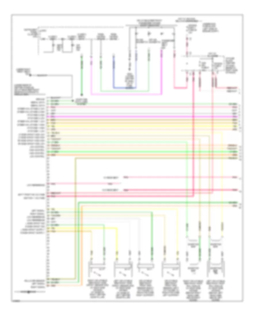
A/T Wiring Diagram (1 of 2) for Suzuki XL7 Luxury 2009
List of elements for A/T Wiring Diagram (1 of 2) for Suzuki XL7 Luxury 2009:
- (pc) solenoid valve 1
- (pc) solenoid valve 2
- (pc) solenoid valve 3
- (pc) solenoid valve 4
- (pc) solenoid valve 5
- 12 volt ref
- Acc
- Automatic transmission
- Automatic transmission fluid temperature (tft) sensor
- Body control module (bcm) (center of dash, behind hvac control module)
- Computer data lines system
- Control solenoid valve assembly
- G109 (right rear of cylinder head)
- Ground
- Hi spd gmlan srl data bus+
- Hi spd gmlan srl data bus-
- Hot at all times
- Hot w/ ign relay energized
- Ign
- Ign voltage
- Ignition switch
- Ignition voltage
- Off
- Pc/tcc solenoid valve
- Pnk
- Pressure control (pc) solenoid valve 1
- Pressure control (pc) solenoid valve 2
- Pressure control (pc) solenoid valve 3
- Pressure control (pc) solenoid valve 4
- Pressure control (pc) solenoid valve 5
- Shift solenoid (ss) valve 1
- Shift solenoid (ss) valve 2
- Start
- Stop lamp switch signal
- Tan
- Tap up/tap down sw sig
- Tcm batt fuse 15a
- Torque converter clutch (tcc) pressure control (pc) solenoid valve
- Trans fuse 10a
- Transmission control module (tcm)
- Underhood fuse block (left side of engine compt)
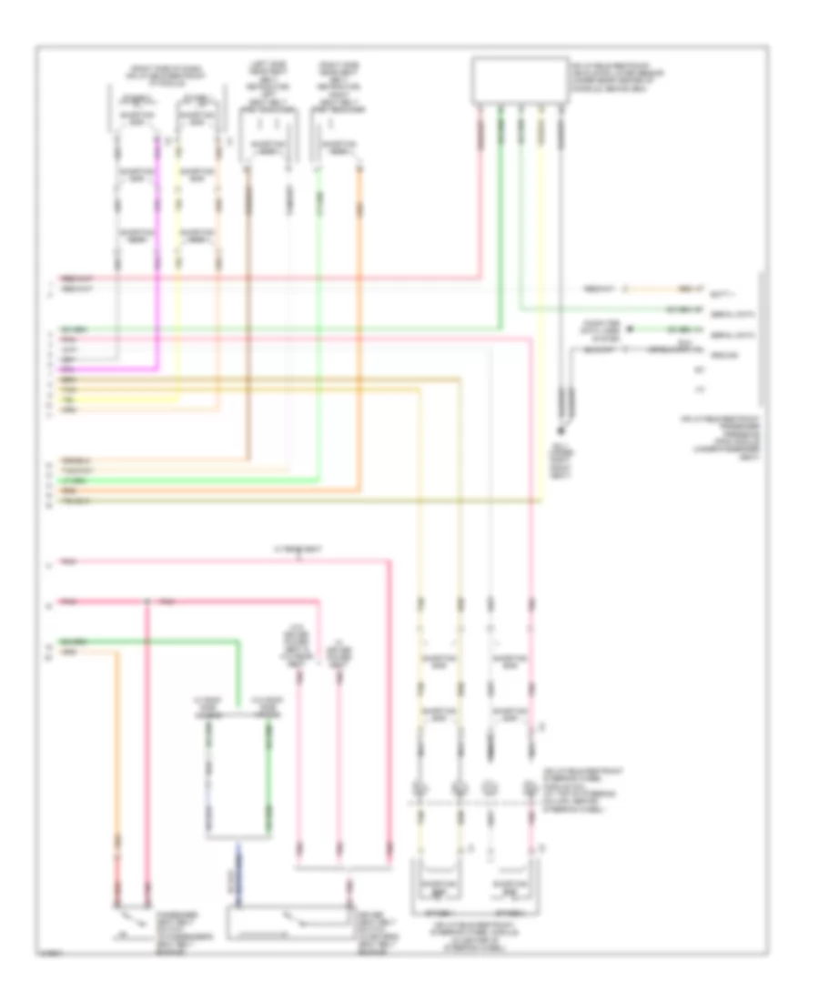
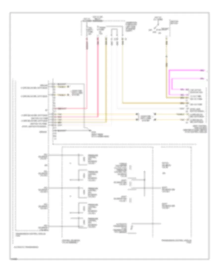
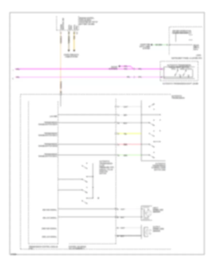
A/T Wiring Diagram (2 of 2) for Suzuki XL7 Luxury 2009
List of elements for A/T Wiring Diagram (2 of 2) for Suzuki XL7 Luxury 2009:
- Automatic transmission
- Automatic transmission fluid pressure (tfp) manual valve position switch
- Automatic transmission internal mode switch (ims)
- Automatic transmission manual shift switch
- Automatic transmission shift lever
- Bus+ data
- Computer data lines system
- Control solenoid valve assembly
- Data bus-
- Driver information center (dic) display
- Engine control module (ecm) (mounted on top of battery cover)
- Gmlan serial data
- Input speed (iss) sensor
- Instrument panel cluster (ipc)
- Iss high signal
- Iss low signal
- Logic
- Low ref
- Oss high signal
- Oss low signal
- Output speed (oss) sensor
- Park/ neutral sig
- Red
- Sound systems
- Tan
- Transmission control module (tcm)
- Transmission range switch sig a
- Transmission range switch sig b
- Transmission range switch sig c
- Transmission range switch sig p
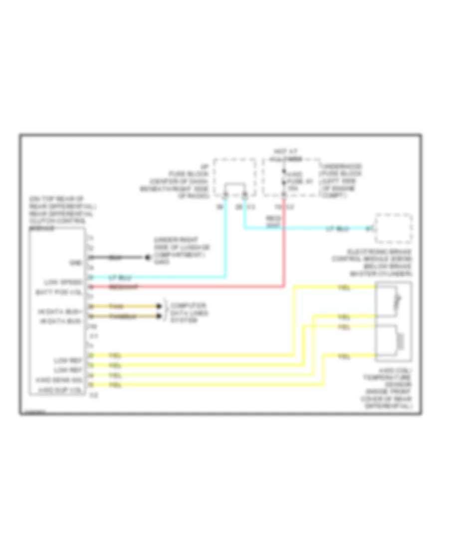
AWD Wiring Diagram for Suzuki XL7 Luxury 2009
List of elements for AWD Wiring Diagram for Suzuki XL7 Luxury 2009:
- (on top rear of rear differential) rear differential clutch control module
- (under right side of luggage compartment) g403
- Awd coil/ temperature sensor (inside front cover of rear differential)
- Awd fuse 41 15a
- Awd sens sig
- Awd sup vol
- Batt pos vol
- Computer data lines system
- Electronic brake control module (ebcm) (below brake master cylinder)
- Gnd
- Hi data bus+
- Hi data bus-
- Hot at all times
- I/p fuse block (center of dash, beneath right side of radio)
- Low ref
- Low speed
- Tan
- Underhood fuse block (left side of engine compt)
TRUNK, TAILGATE, FUEL DOOR
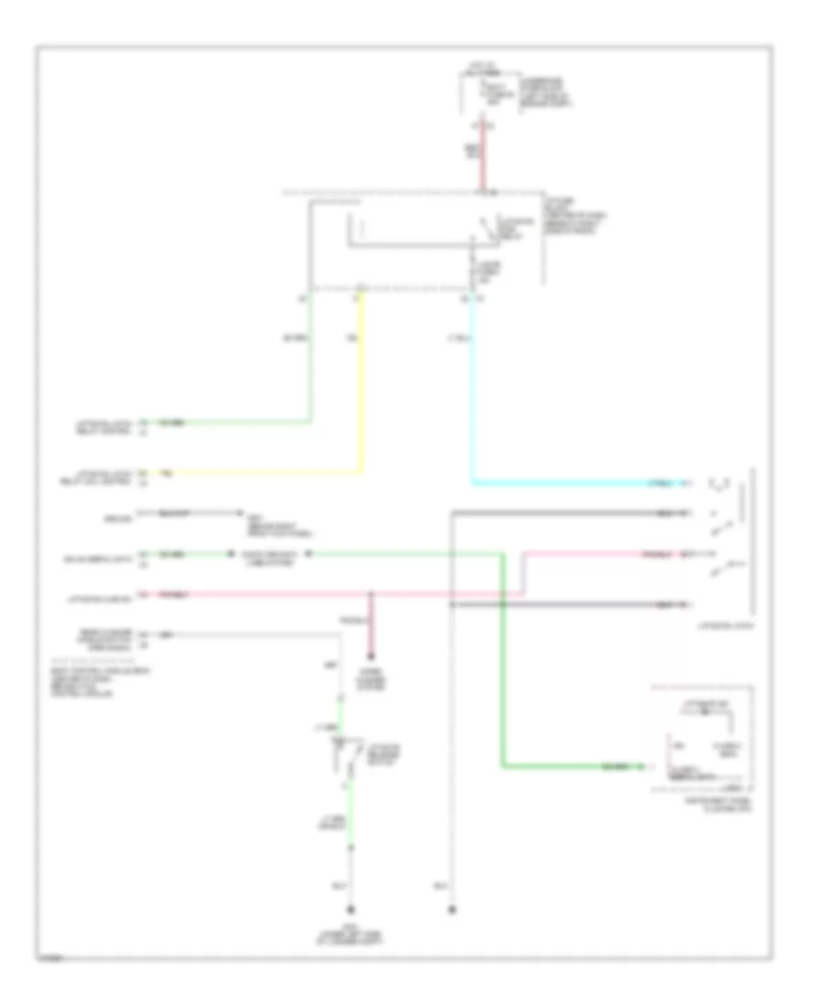
Liftgate Release Wiring Diagram for Suzuki XL7 Luxury 2009
List of elements for Liftgate Release Wiring Diagram for Suzuki XL7 Luxury 2009:
- (bcm)
- Batt fuse 50 50a
- Body control module (bcm) (center of dash, behind hvac control module)
- Class 2
- Class 2 serial data
- Computer data lines system
- G201 (behind right front kick panel)
- G401 (under left side of luggage compt)
- Gmlan serial data
- Ground
- Hot at all times
- I/p fuse block (center of dash, beneath right side of radio)
- Ign
- Instrument panel cluster (ipc)
- L/gate fuse 4 15a
- Liftgate ajar sw
- Liftgate ind
- Liftgate latch
- Liftgate latch relay coil control x4
- Liftgate latch relay control x7
- Liftgate pcb relay
- Liftgate release switch
- Logic
- Rear closure handle switch open signal
- Underhood fuse block (left side of engine compt)
- Wiper/ washer system
WARNING SYSTEMS
Warning Systems Wiring Diagram for Suzuki XL7 Luxury 2009
List of elements for Warning Systems Wiring Diagram for Suzuki XL7 Luxury 2009:
- (behind right front kick panel) g201
- Ajar sw sig
- Auto
- Batt pos volt
- Bcm fuse 20 10a
- Body control module (bcm) (center of dash, behind hvac control module)
- Driver door latch
- Driver seat belt switch (in driver's seat belt buckle)
- Drv dr ajar sw sig
- G201 (behind right front kick panel)
- G311 (under right front seat)
- G401 (under left side of luggage compt)
- Gmlan serial data
- Gnd
- Head
- Hot at all times
- I/p fuse block (center of dash, beneath right side of radio)
- I/p fuse block (center of dash, beneath right x3 side of radio)
- Ign sw fuse 19 2a
- Ignition switch
- Inflatable restraint sensing & diagnostic module (sdm) (under rear of center console)
- Instrument panel cluster (ipc)
- Jx200 (behind left side of instrument panel)
- Key in ign sw sig
- Key in ignition switch
- Left rear door latch
- Left seat belt sw
- Liftgate latch
- Logic
- Low ref
- Off
- Park
- Park brake switch (at base of park brake lever)
- Pass dr ajar sw sig
- Passenger door latch
- Pnk
- Prk brk sw sig
- Prk lmp sw on sig
- Right rear door latch
- Seat belt ind
- Serial data
- Sound systems
- Turn signal/ multi-function switch
- W/o rear seat
- Wiper/ washer system
WIPER/WASHER
Wiper/Washer Wiring Diagram for Suzuki XL7 Luxury 2009
List of elements for Wiper/Washer Wiring Diagram for Suzuki XL7 Luxury 2009:
- Body control module (center of dash, behind hvac control module)
- Door locks system
- Fog lamp
- Frt washer pcb relay
- Frt wpr fuse 36 25a
- Ftr/rear wsw fuse 45 10a
- G101 (at left front corner of vehicle)
- G201 (behind right front kick panel)
- G401 (under left side of luggage compt)
- Gnd
- Hi sig ctrl
- Hot at all times
- I/p fuse block (center of dash, beneath right side of radio)
- Ign
- Ign vol
- Int
- Interior lights system
- Logic
- Mist
- Off
- Pnk
- Rear window wiper motor (in rear tailgate)
- Rear window wiper/washer/ fog lamp switch
- Rear wpr fuse 3 20a
- Rr wash pcb relay
- Tan
- Underhood fuse block (left side of engine compt)
- Washer
- Washer rly ctrl
- Washer switch
- Windshield washer fluid pump (at bas of washer fluid reservoir)
- Windshield wiper/ washer motor (under left side of cowl, integral to front wiper module assembly)
- Windshield wiper/ washer switch
- Wip sw hi sig
- Wip sw lo sig
- Wiper
- Wiper high pcb relay
- Wiper motor sw sig
- Wiper pcb relay
- Wiper sw sig
- Wiper sw sig 2

 Čeština
 Dansk
Dansk Deutsch
 Ελληνικά
 English
 English
 Español
 Suomi
Suomi Français
 Français
 עברית
עברית Hrvatski
 Magyar
 Italiano
 日本語
日本語 한국어
한국어 Nederlands
 Polski
 Português
 Português
 Română
 Русский
 Slovenčina
 Slovenščina
 Türkçe
 中文 (中国)