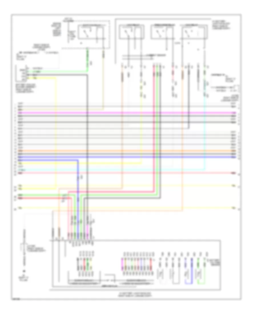
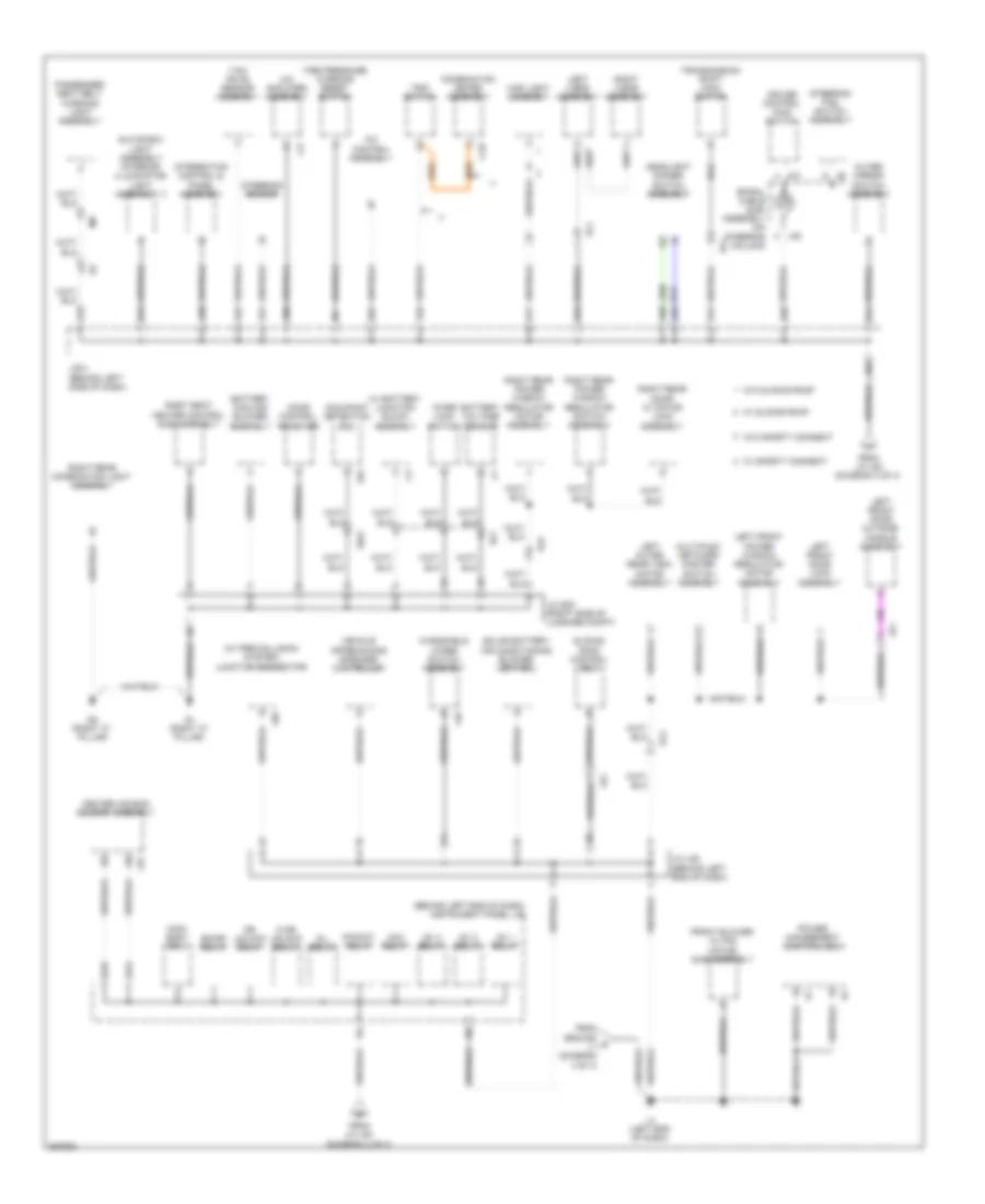
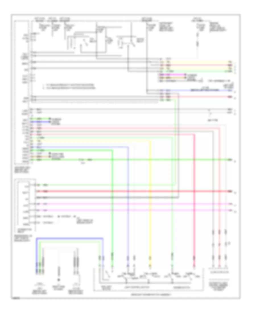
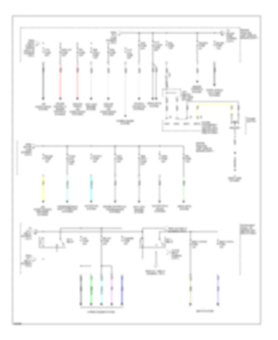
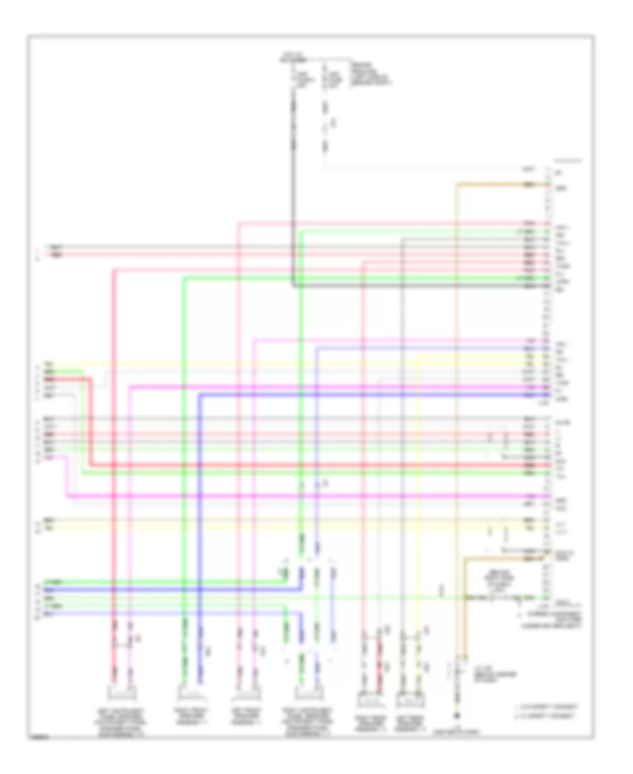
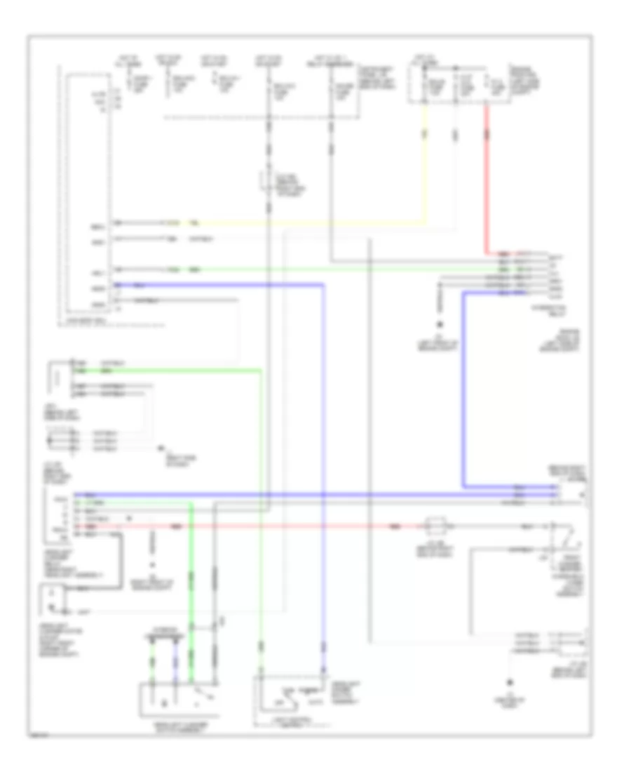
AIR CONDITIONING
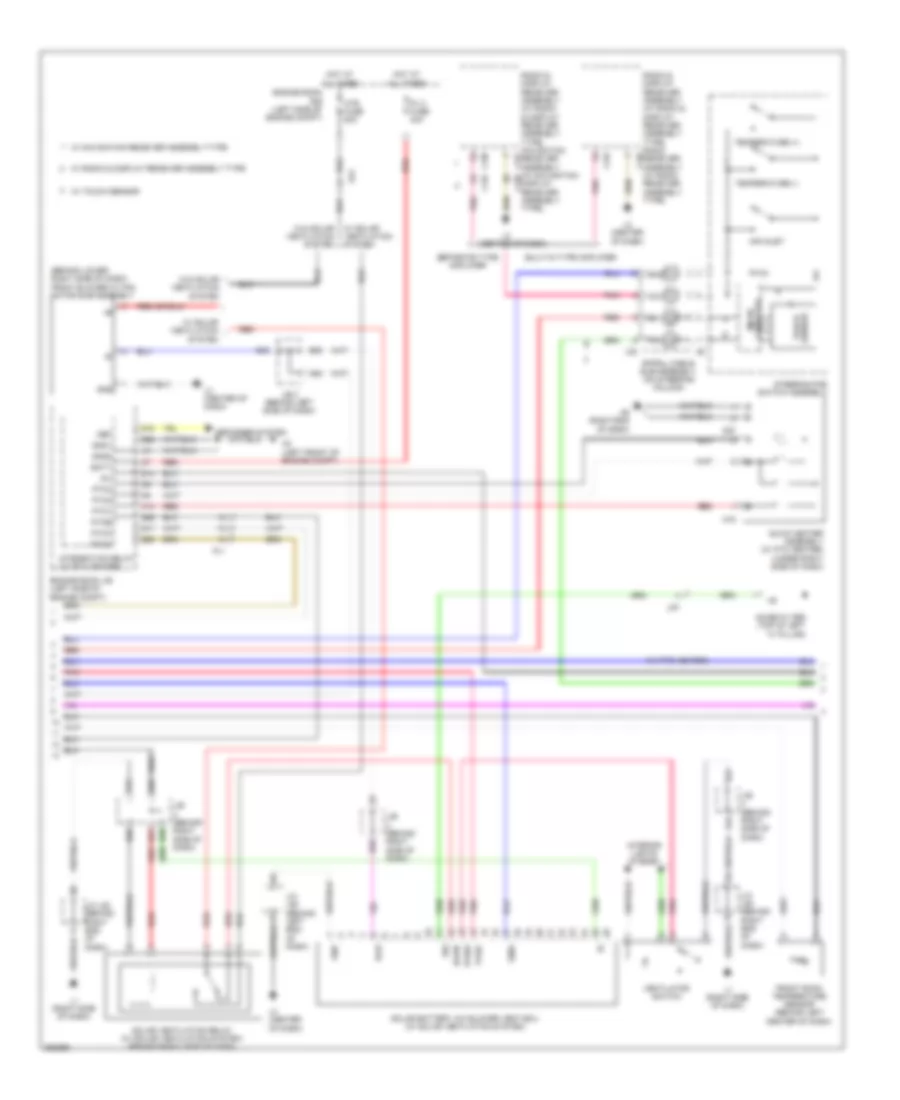
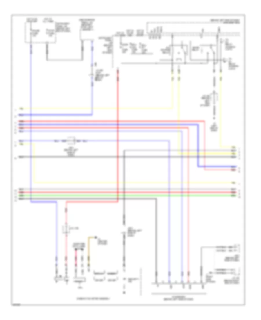
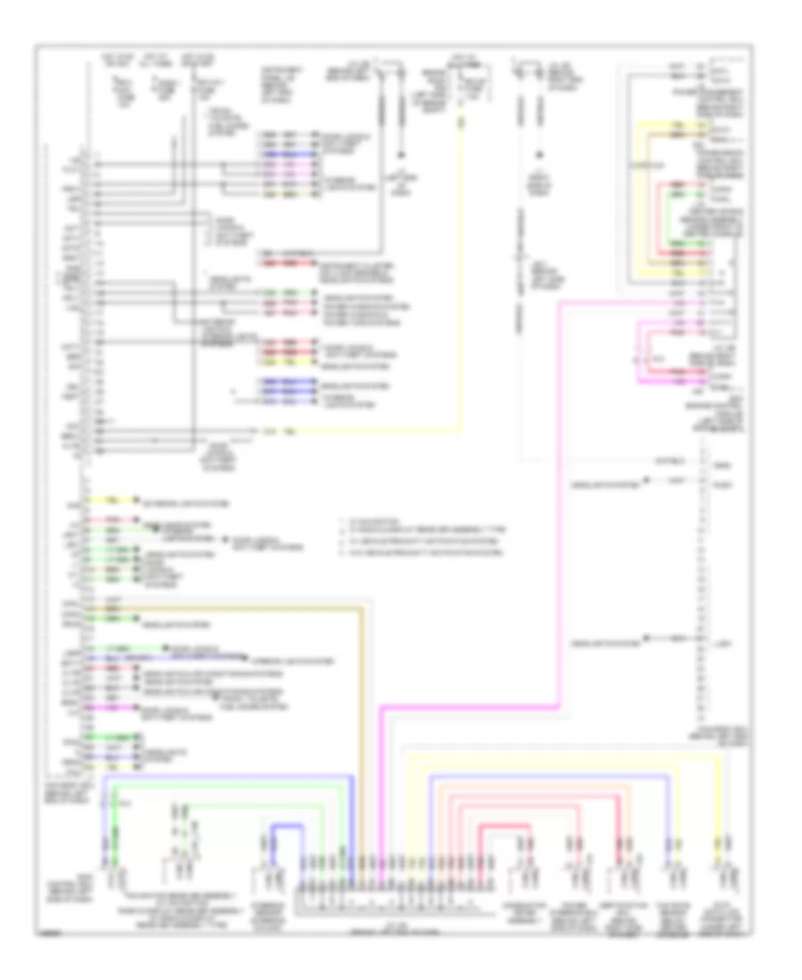
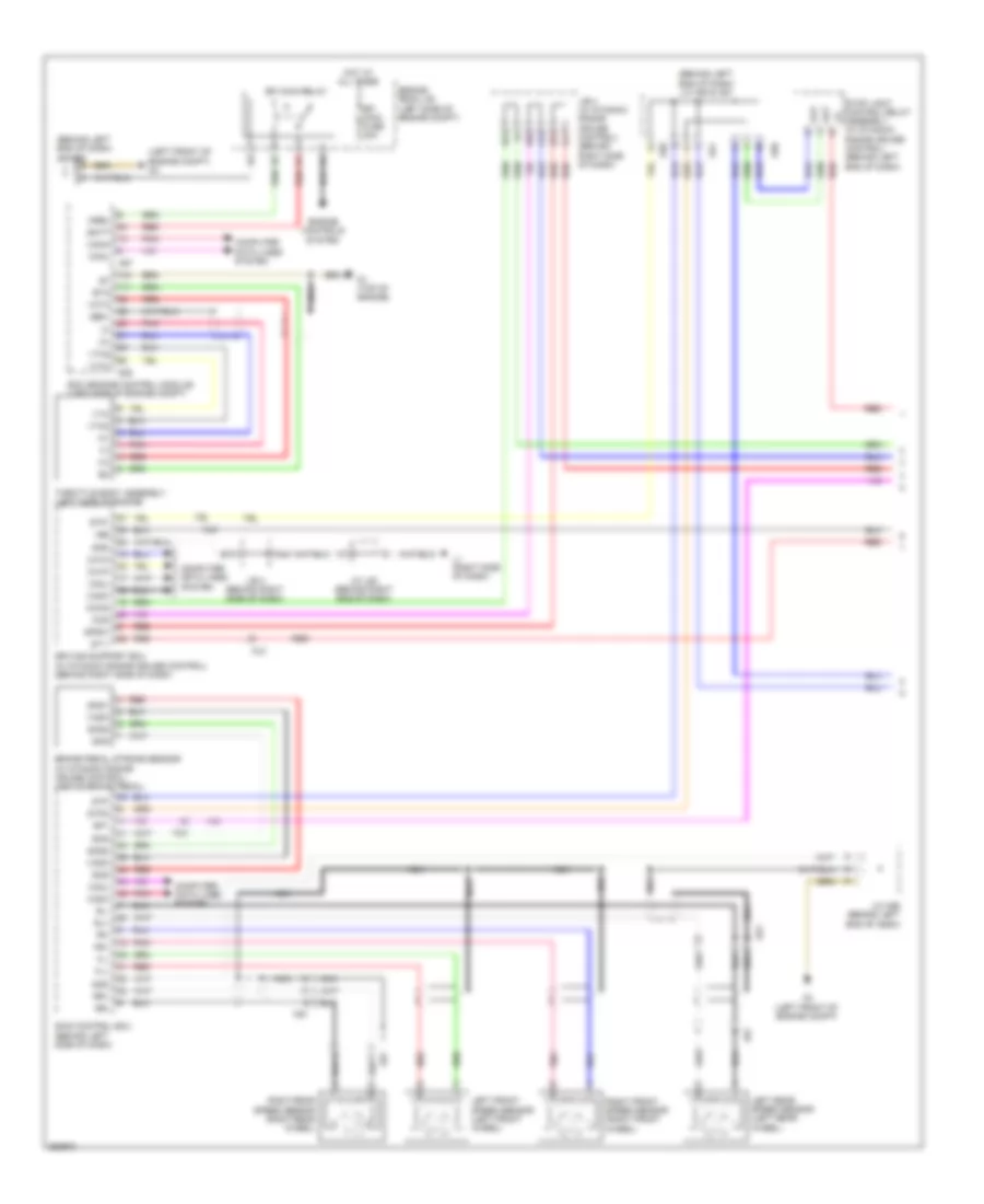
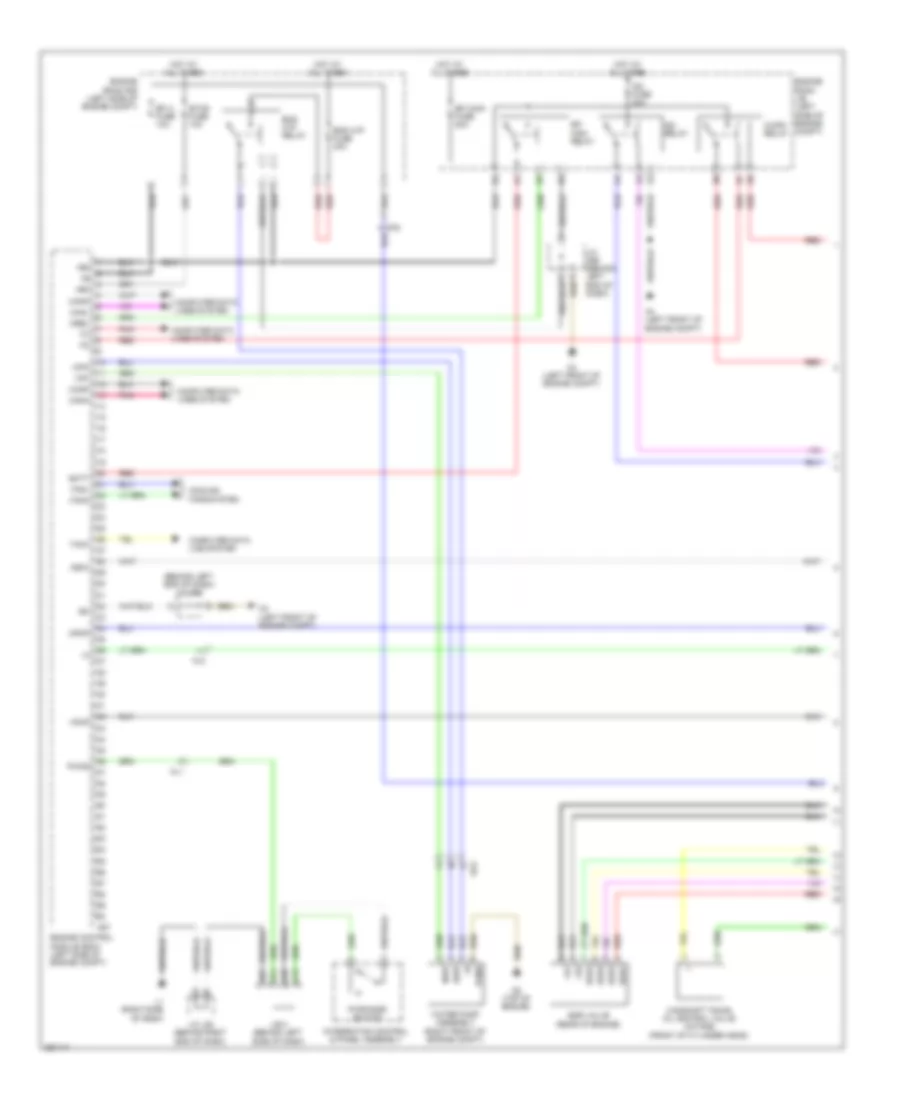
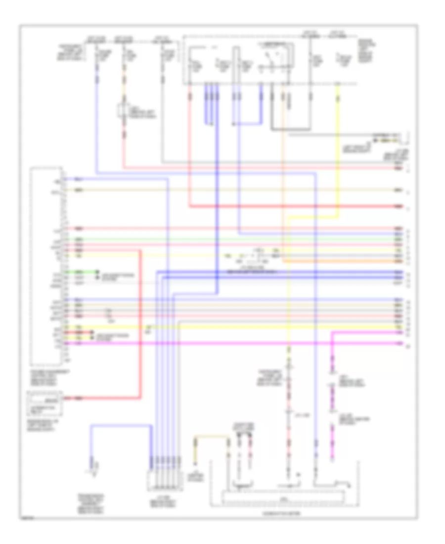
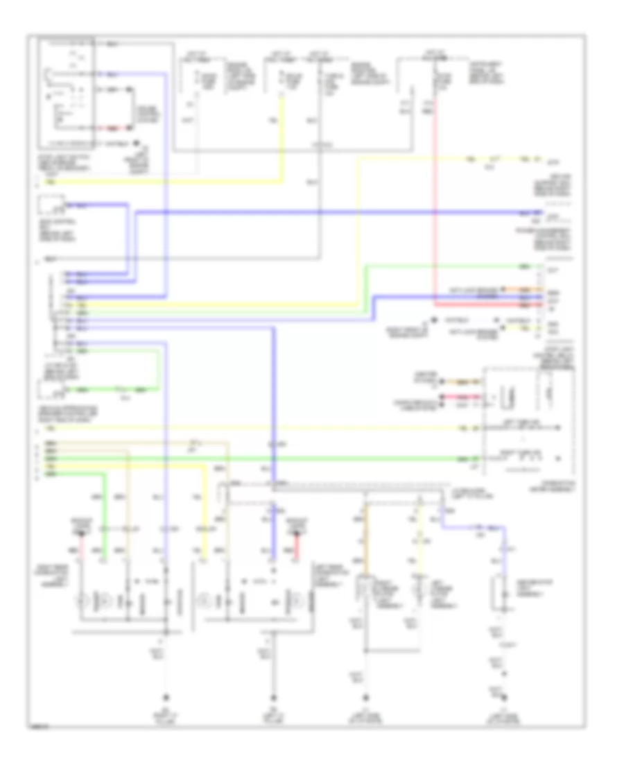
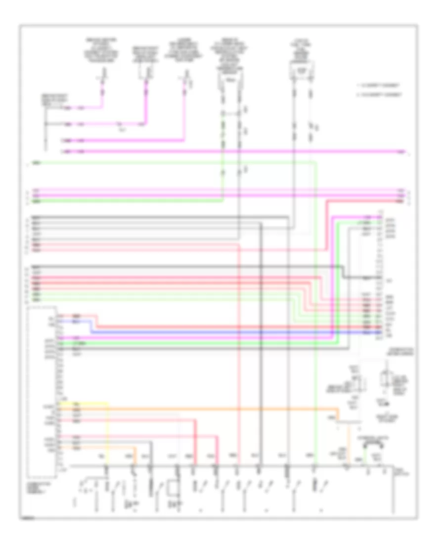
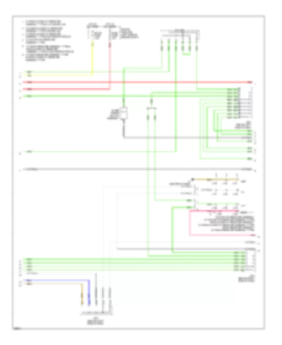
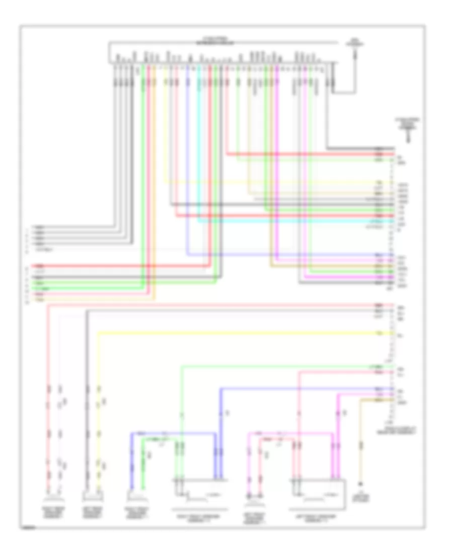
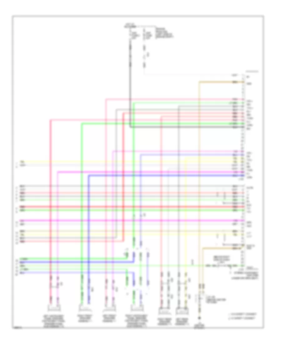
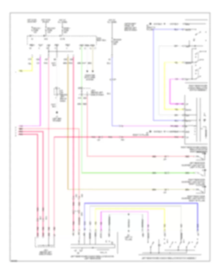
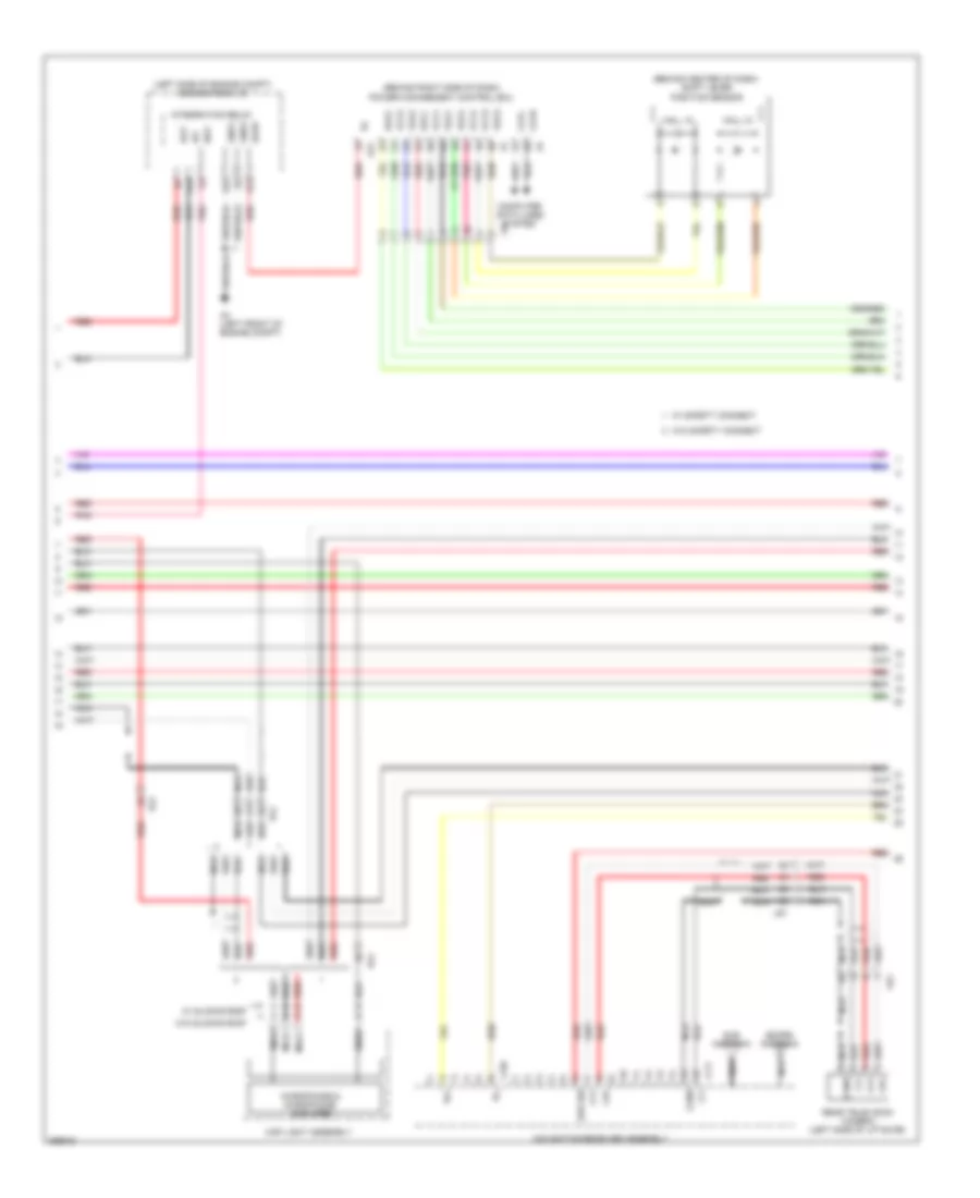
Automatic A/C Wiring Diagram (1 of 3) for Toyota Prius Plug-in 2012
 https://portal-diagnostov.com/license.html
Automotive Electricians Portal FZCO
Automotive Electricians Portal FZCO
https://portal-diagnostov.com/license.html
https://portal-diagnostov.com/license.html
Automotive Electricians Portal FZCO
Automotive Electricians Portal FZCO
List of elements for Automatic A/C Wiring Diagram (1 of 3) for Toyota Prius Plug-in 2012:
- (w/ ptc heater)
- A/c amplifier assembly (behind center of dash)
- A/c blower assembly (behind center of dash)
- A/c control assembly
- A/c evaporator temperature sensor
- A/c fuse 10a
- A/c pressure sensor (right rear of engine compt)
- A/c solar sensor
- A19
- A20
- A32
- A50
- A51
- A53
- A64
- A65
- A67
- A75
- A79
- A80
- Acc
- Al1
- Ambient temperature sensor (behind center of front bumper)
- Automatic light control sensor (upper right side of dash)
- B bus
- B50
- B54
- B55
- B66
- B72
- B74
- B84
- B86
- Becu
- Blw
- Bus
- Bus g
- C18
- C28
- Canh
- Canl
- Cltb
- Clte
- Computer data lines system
- Connector housing color (black)
- Connector housing color (red)
- Da9
- Damper servo motor (air inlet)
- Damper servo motor (air mix)
- Damper servo motor (air vent mode)
- Defogger system
- Eco mode switch
- Ecos
- Ecu
- Ecu-acc fuse 10a
- Ecu-b fuse 7.5a
- Ecu-b3 fuse 10a
- Ecu-ig 1 fuse 10a
- Engine room r/b (left side of engine compt)
- Gnd
- Gnd1
- Gnd2
- Hot at all times
- Hot w/ acc relay energized
- Hot w/ ig1 relay energized
- Hot w/ ig2 relay energized
- Idh
- Ig+
- Ign fuse 10a
- Ill+
- Ill-
- Instrument panel j/b (behind left end of dash)
- Integration control & panel assembly
- Interior lights system
- J/b 3 (behind left side of dash)
- J/c a50 & a51 (behind left end of dash)
- J/c l92 (behind left end of dash)
- J/c l93 (behind right end of dash)
- L1 (right side of dash)
- L17
- L3 (left end of dash)
- Li1
- Lin1
- Main body ecu (behind left end of dash)
- Nsha
- Pnk
- Pre
- Ptc1
- Ptc2
- Ptc3
- Pvsw
- Rdef
- Rear window defogger switch
- Red
- S5-3
- Sg-1
- Sg-2
- Sga
- Sslr
- Swo
- Tam
- Tea
- Tx+
- Z11
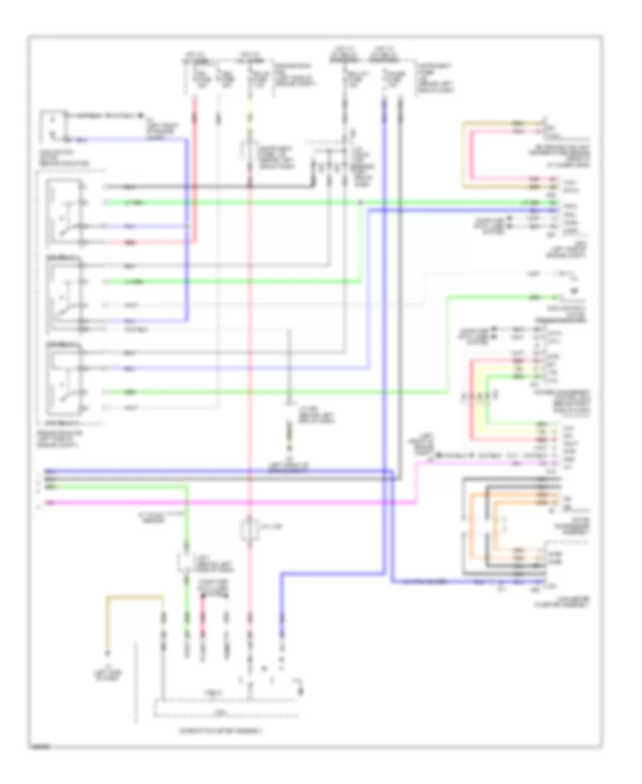
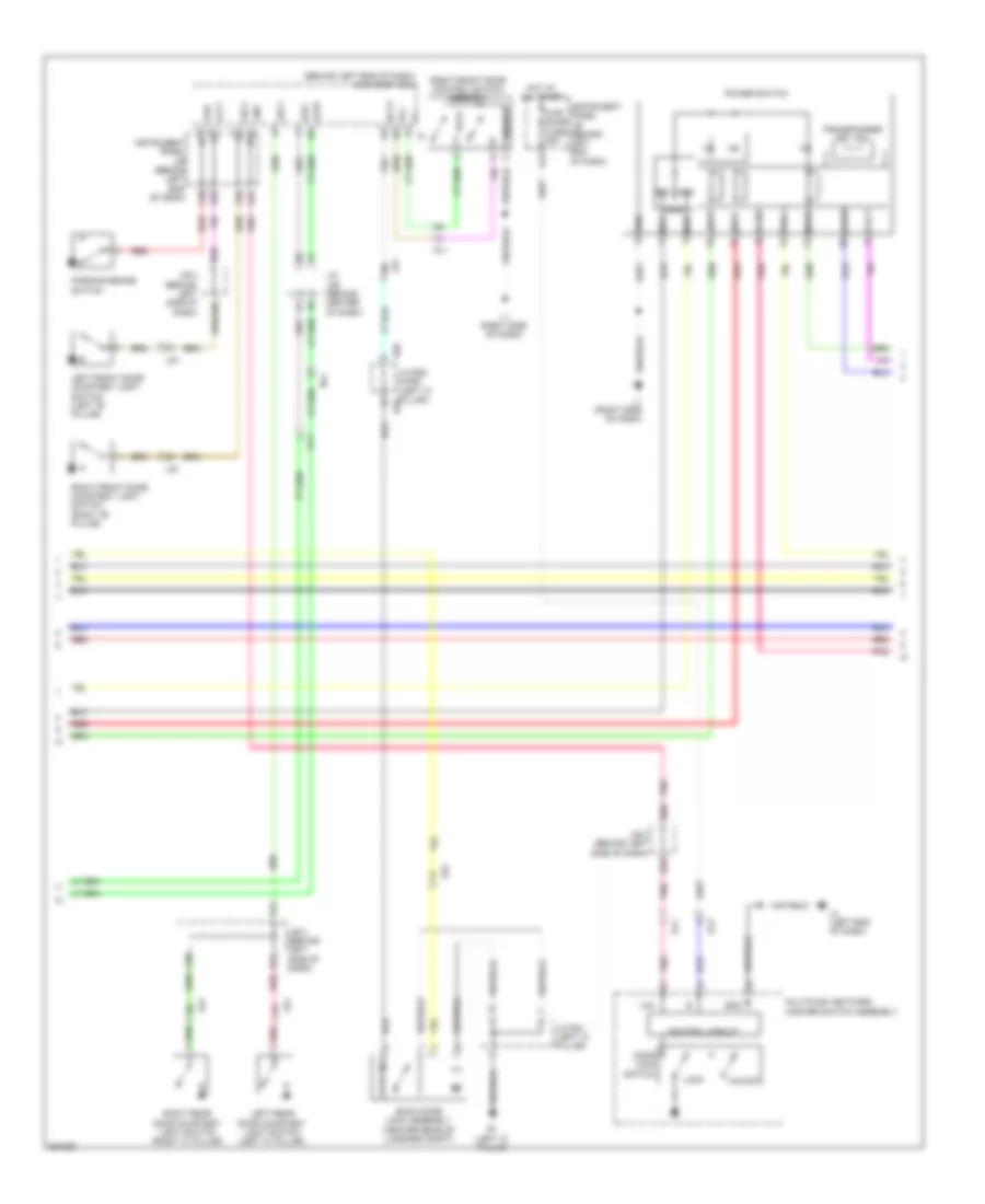
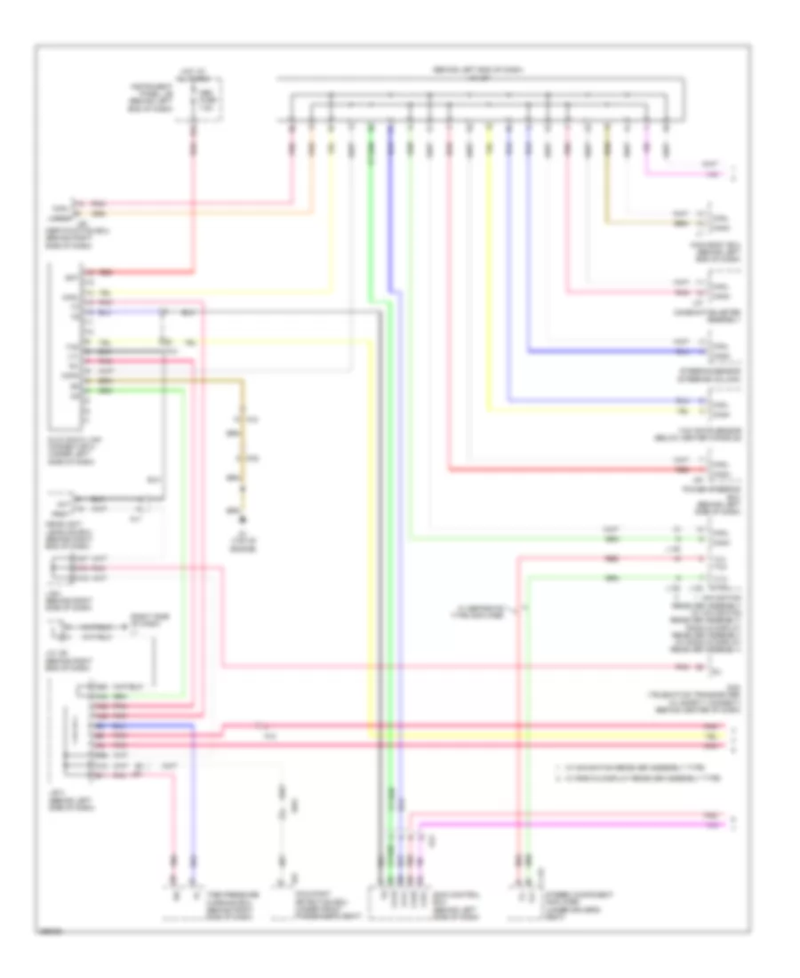
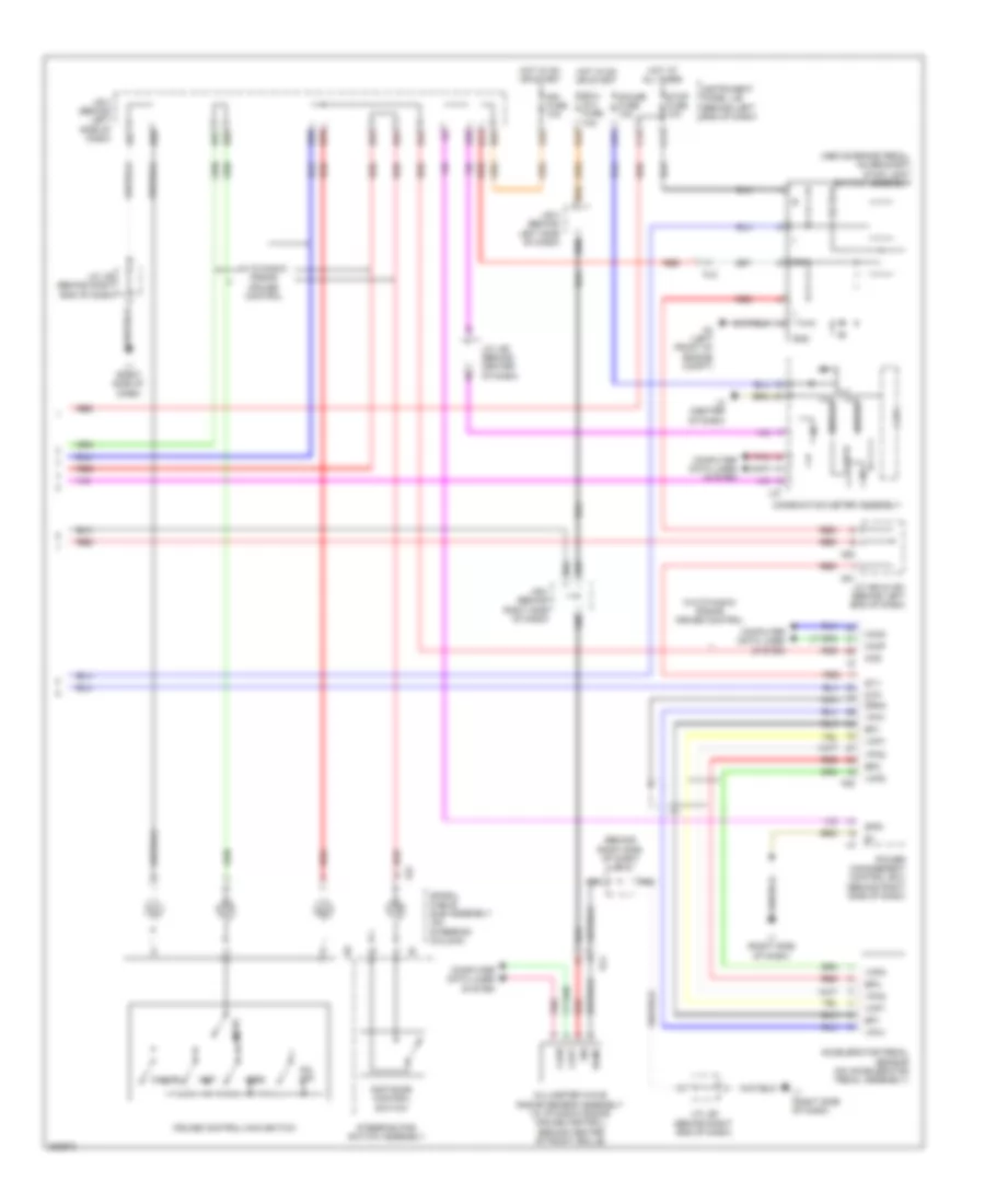
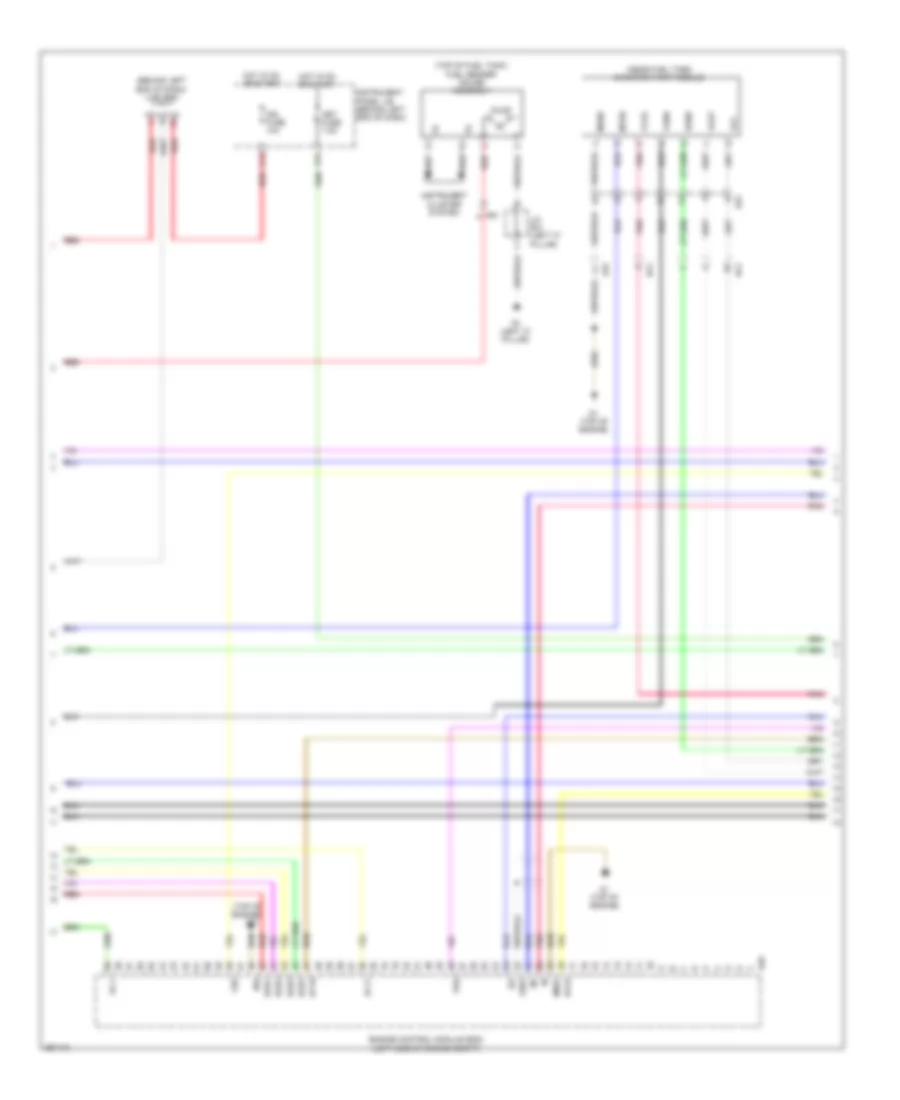
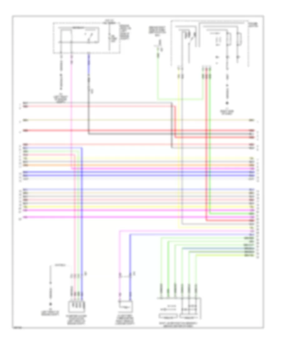
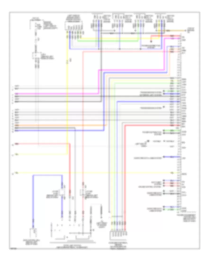
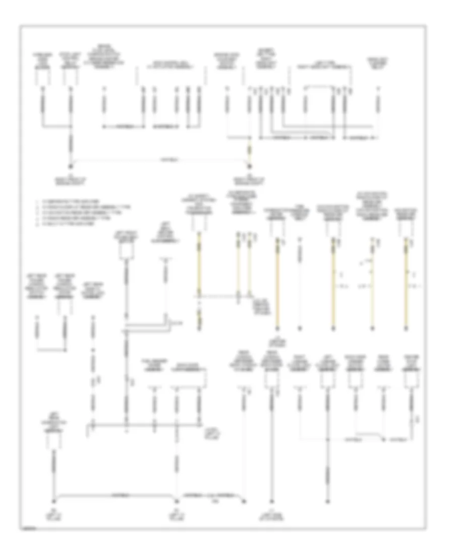
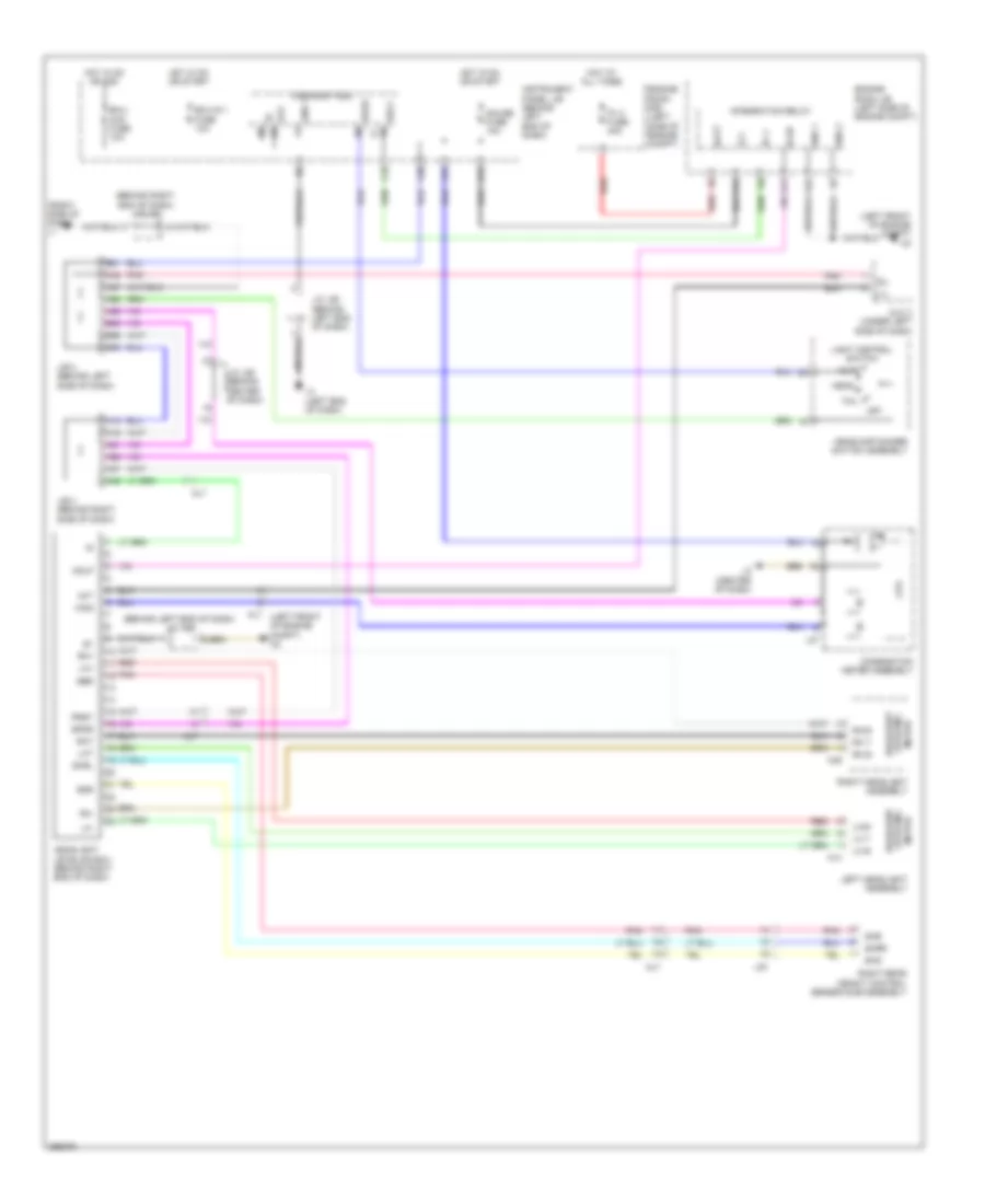
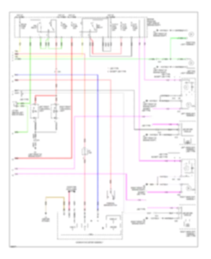
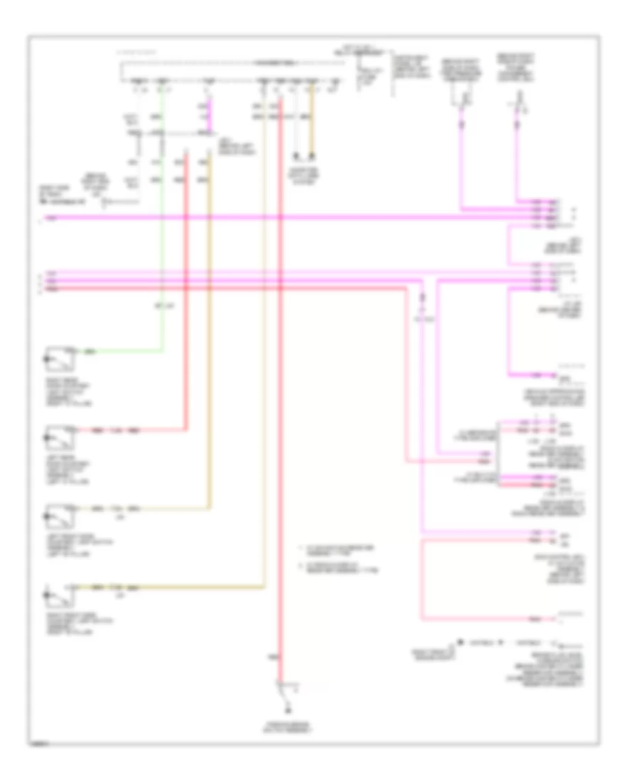
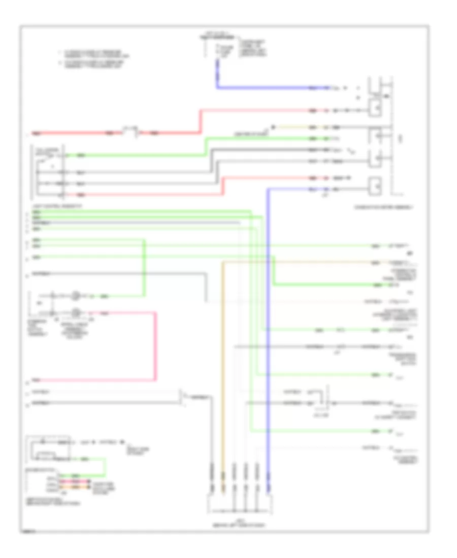
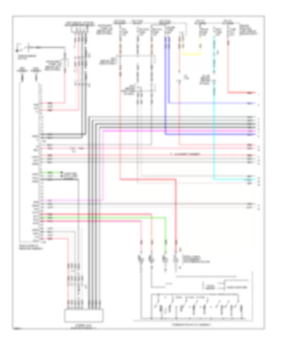
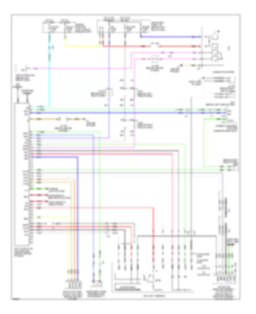
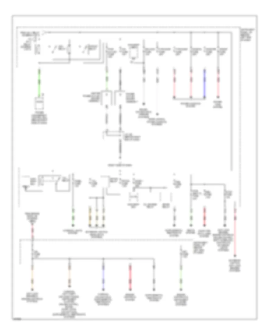
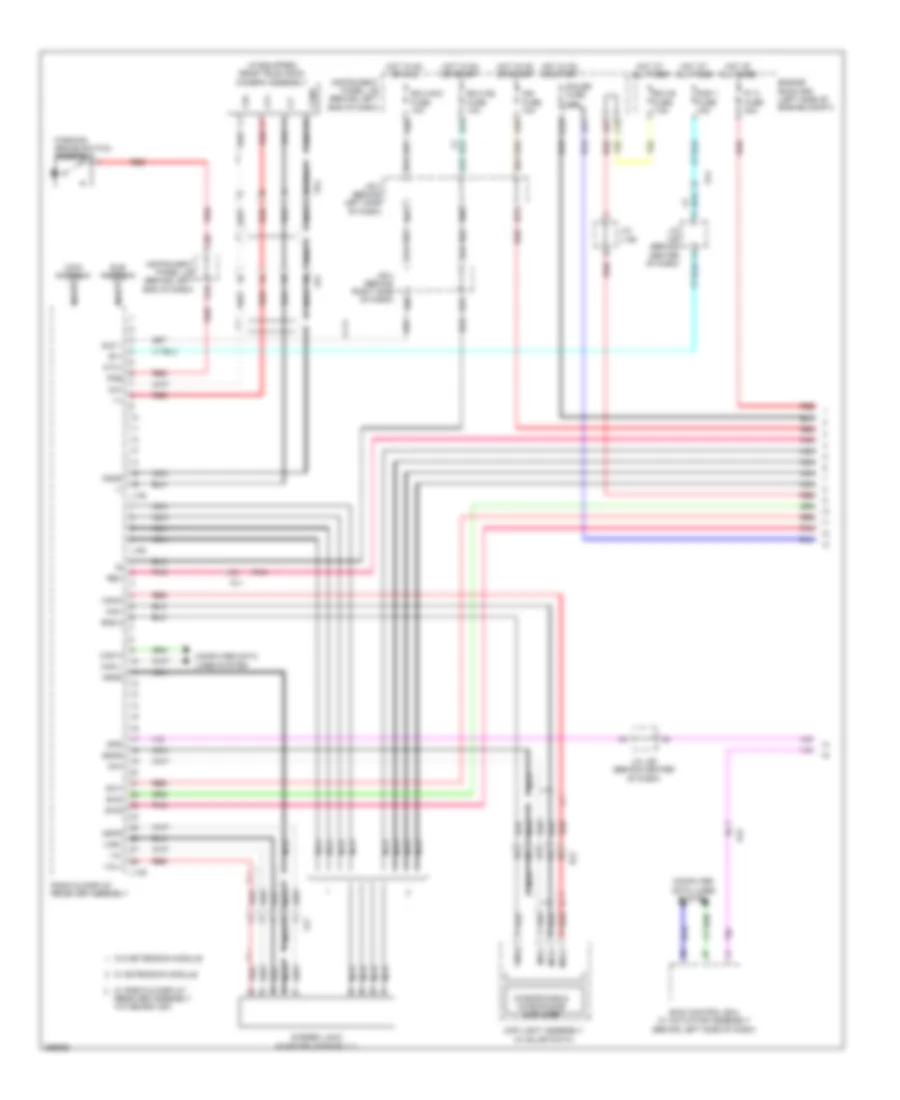
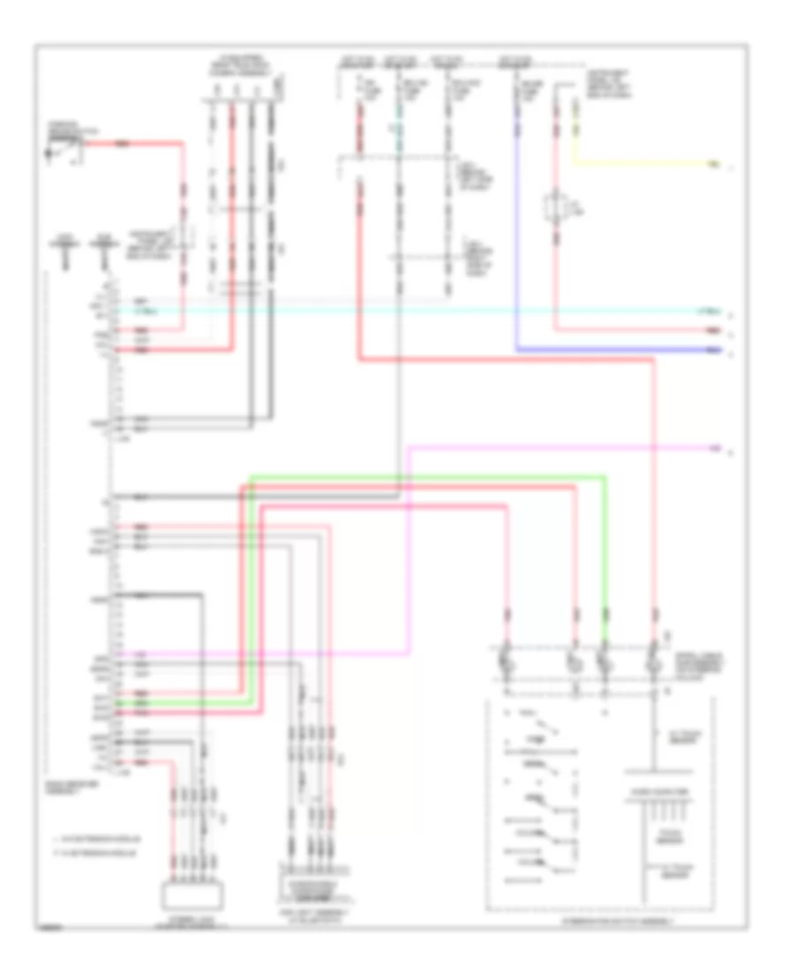
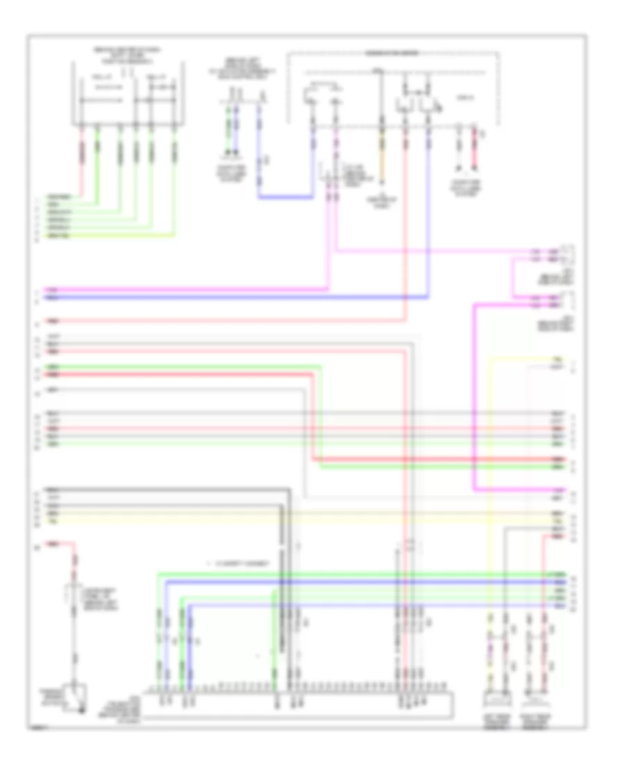
Automatic A/C Wiring Diagram (2 of 3) for Toyota Prius Plug-in 2012
List of elements for Automatic A/C Wiring Diagram (2 of 3) for Toyota Prius Plug-in 2012:
- (behind lower right side of dash) front blower w/ fan motor sub-assembly
- (center of dash)
- (w/ ptc heater)
- A18
- A19
- A20
- A3 (left front of engine compt)
- A42
- A6 (right end of dash)
- A82
- Ac1
- Air inlet
- Al1
- Al5
- B26
- B27
- B28
- B30
- B31
- B35
- B59
- Batt
- Blw
- Blwb
- Built-in type amplifier
- Def
- Defogger system
- Eau
- Engine room j/b (left side of engine compt)
- Engine room r/b (left side of engine compt)
- Front room temperature sensor (behind left center of dash)
- G14
- G15
- G17
- G22
- G25
- G26
- Gnd
- Gnd1
- Gnd2
- H10
- Hot at all times
- Htr fuse 50a
- Ig1
- Integration relay (w/ ptc heater)
- Interior lights system
- J/b (behind right side of dash)
- J/b 3 (behind left side of dash)
- J/c l92 (behind left end of dash)
- J/c l93 (behind right end of dash)
- L1 (right side of dash)
- L127
- L130
- L146
- L149
- L2 (center of dash)
- L3 (center of dash)
- L52
- Lr1
- Micro computer
- Noise filter (top of left "c" pillar)
- P/i 2 fuse 40a
- Pnk
- Ptc1
- Ptc2
- Ptc3
- Ptca
- Ptcb
- Ptcc
- Pvso
- Pvsw
- Quick heater assembly (w/ ptc heater) (under right side of dash)
- Radio & display receiver assembly (w/ radio & display receiver assembly type) navigation receiver assembly (w/ navigation l138 display receiver assembly type)
- Radio & display receiver assembly (w/ radio & display receiver assembly type) radio receiver assembly (w/ radio receiver assembly type)
- Red
- Sbi
- Sensor touch
- Separate type amplifier
- Sind
- Solar battery a/c blower vent ecu (w/ solar ventilation system)
- Solar ventilation relay (w/ solar ventilation system) (behind right side of dash)
- Spiral cable sub-assembly (on steering column)
- Steering pad switch assembly
- Temperature (+)
- Temperature (-)
- Tx1
- Ventilator switch
- W/ navigation receiver assembly type
- W/ radio & display receiver assembly type
- W/ solar ventilation system
- W/ touch sensor
- W/o solar ventilation system
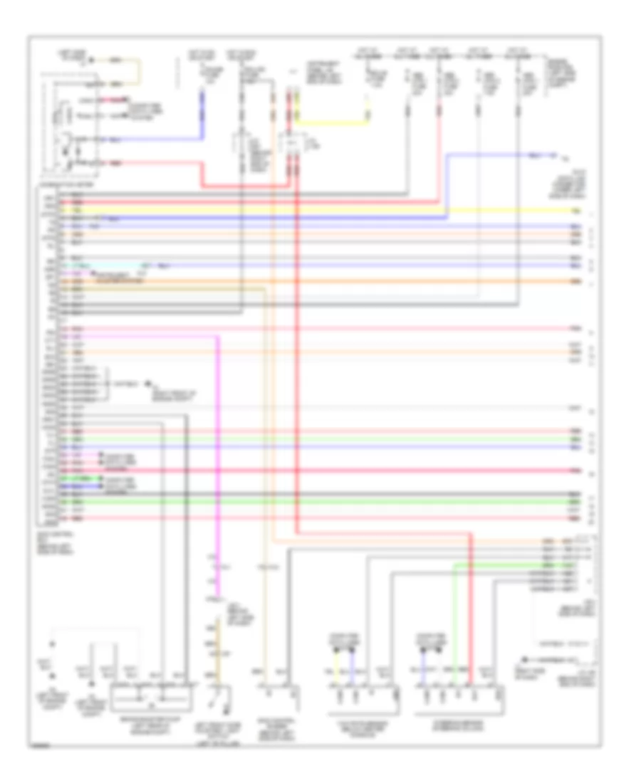
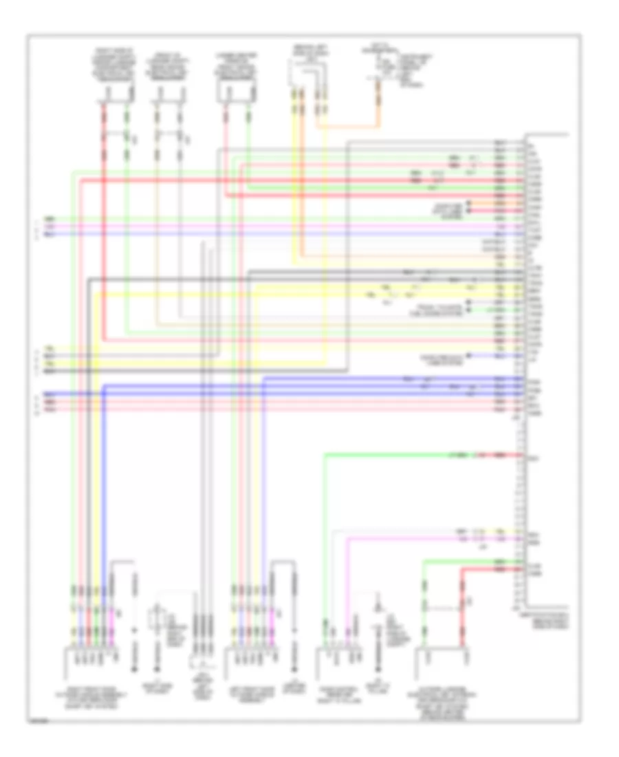
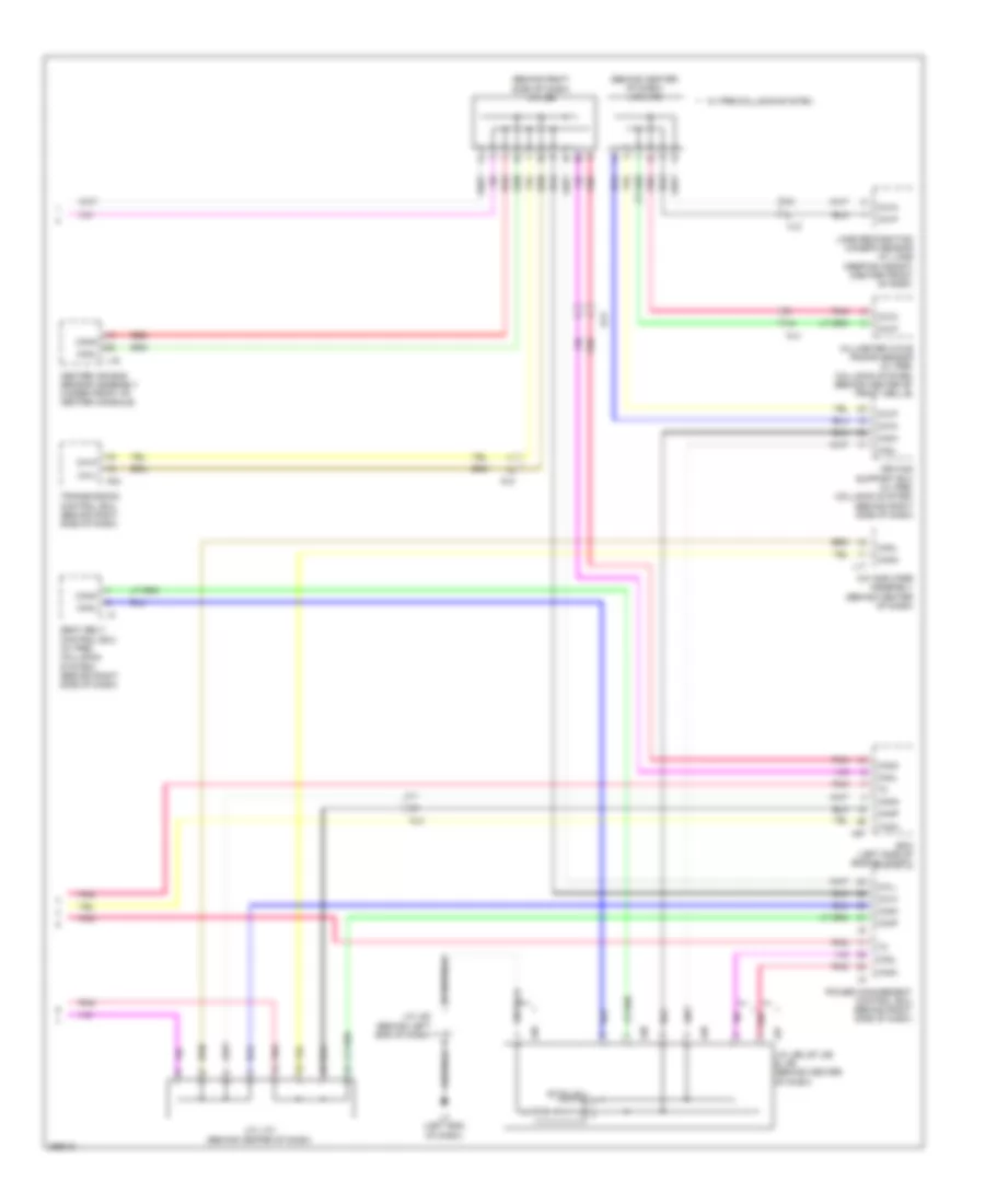
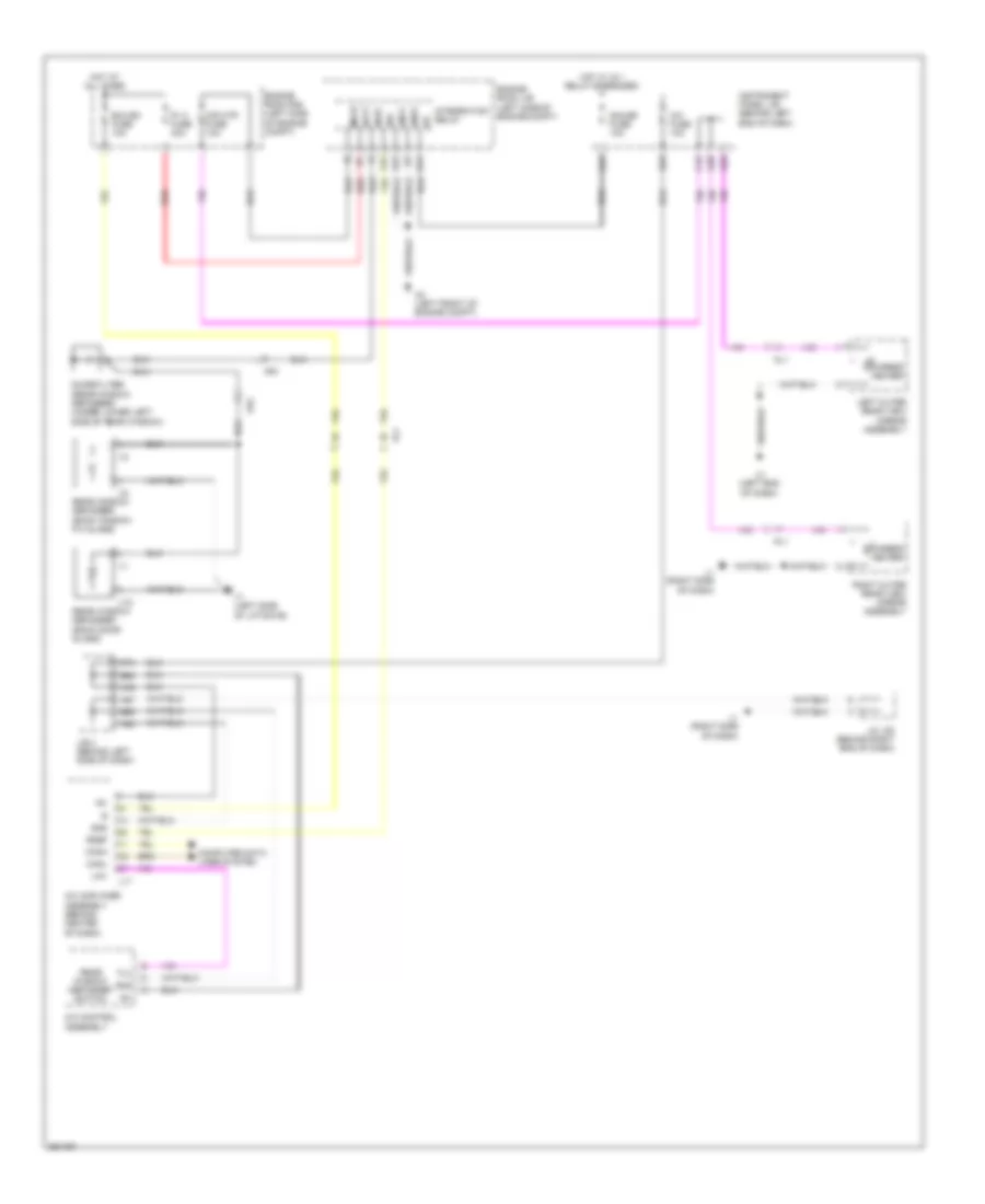
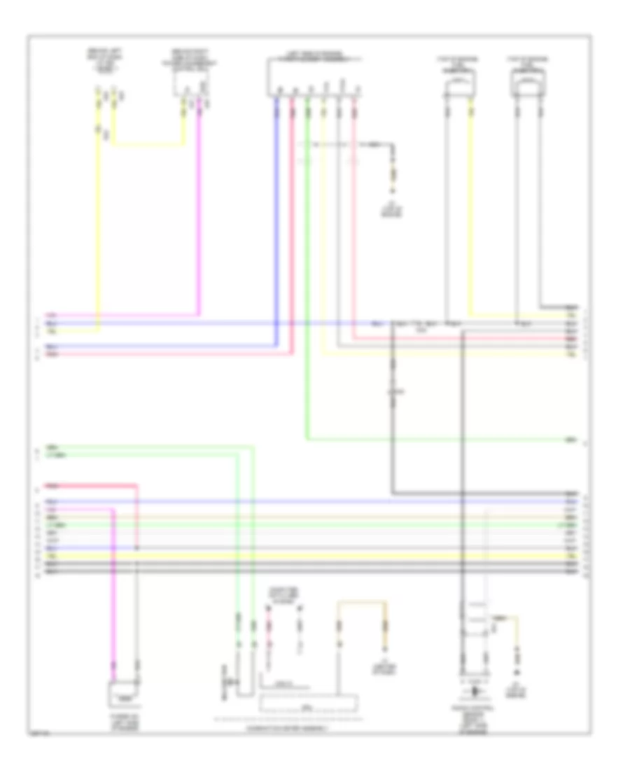
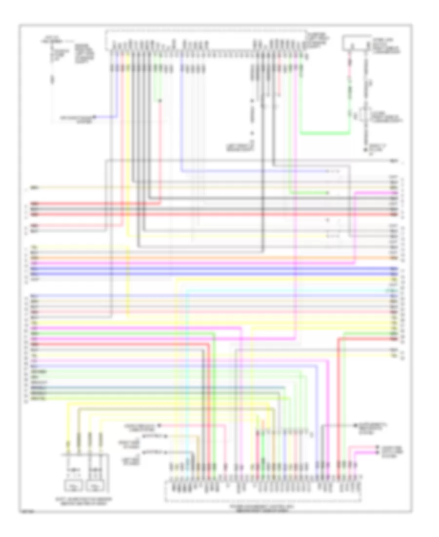
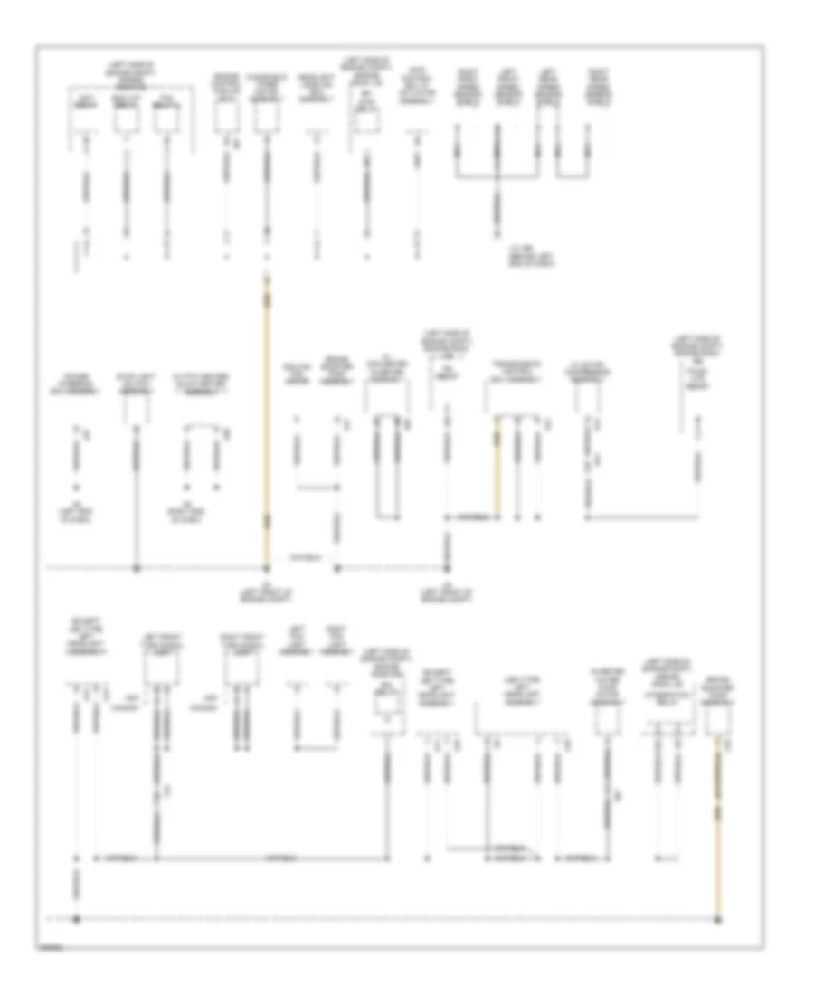
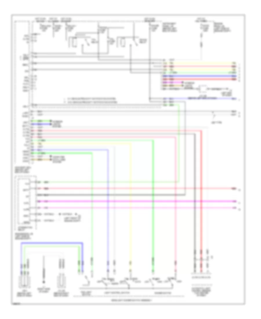
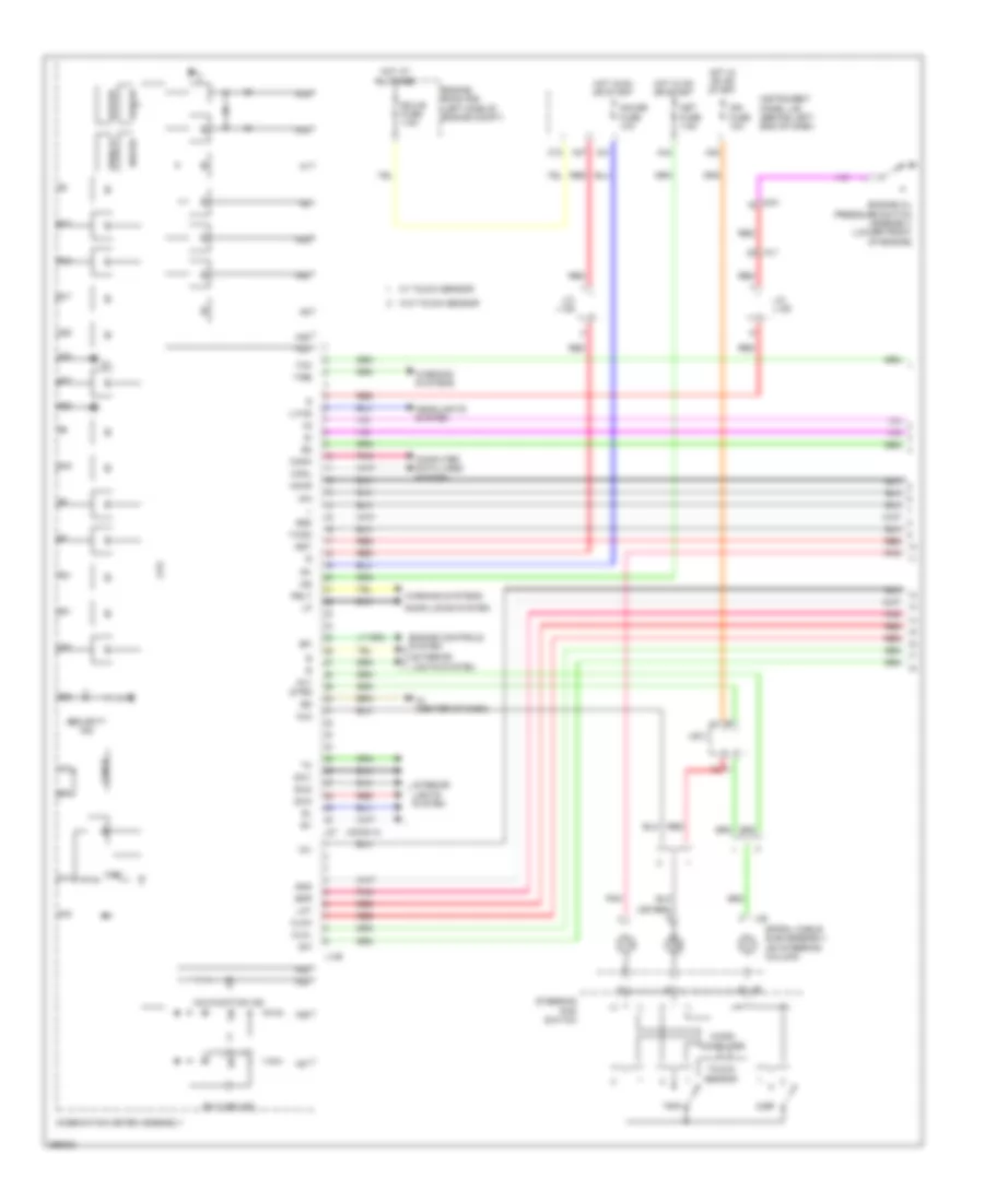
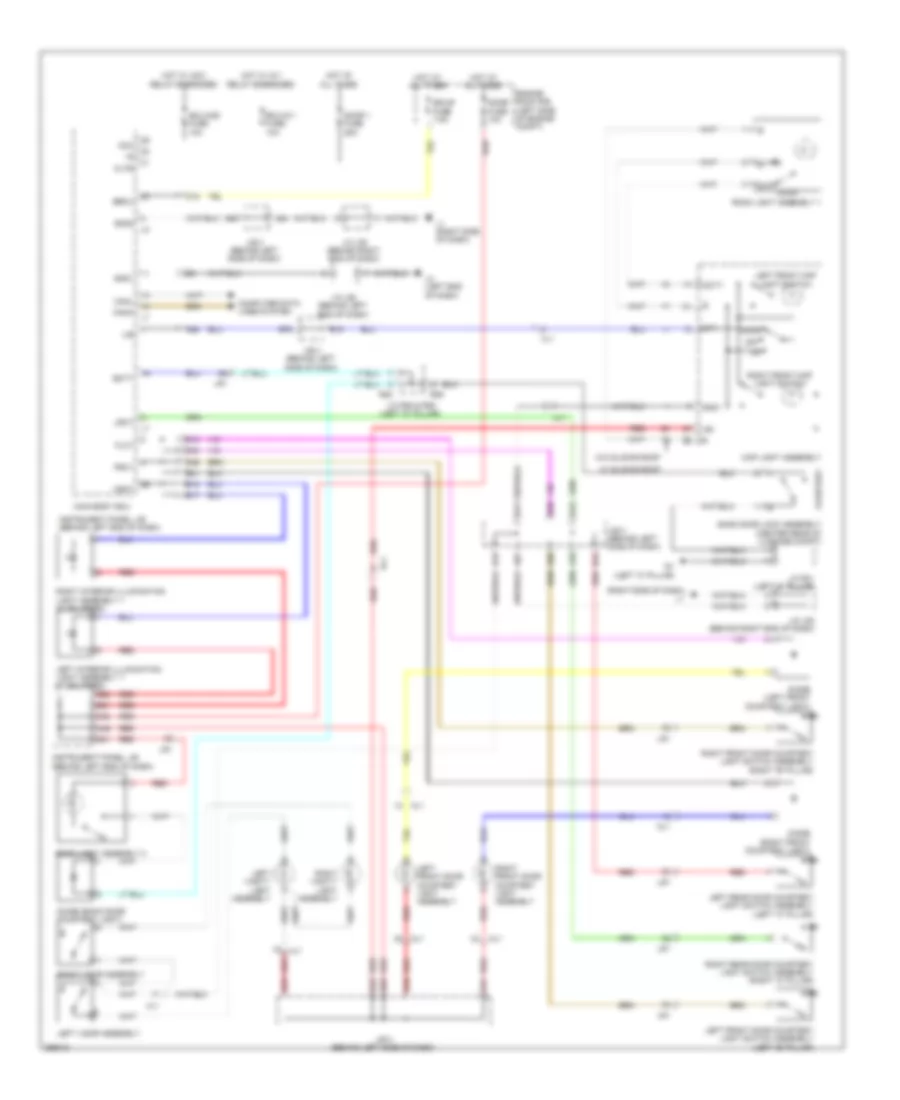
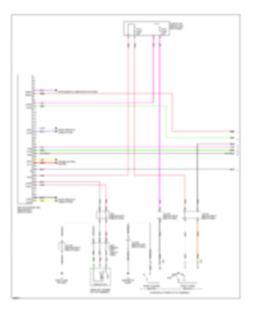
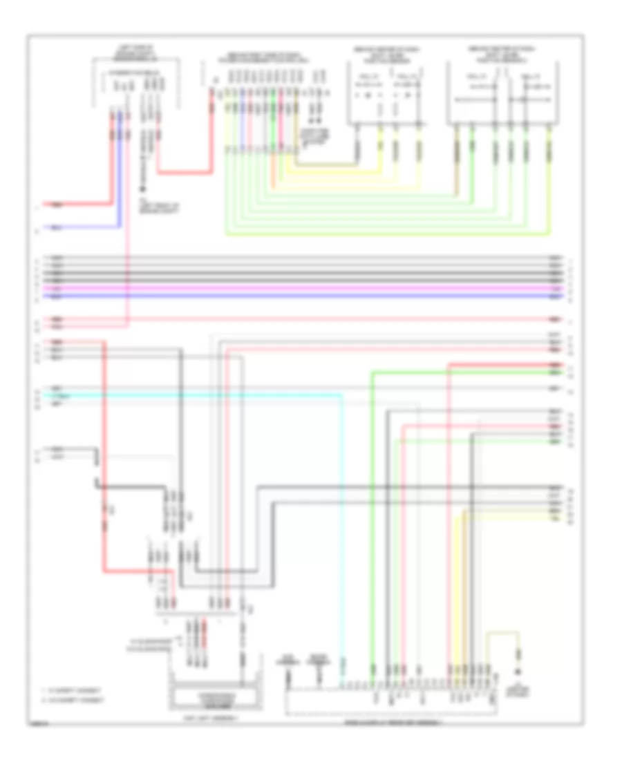
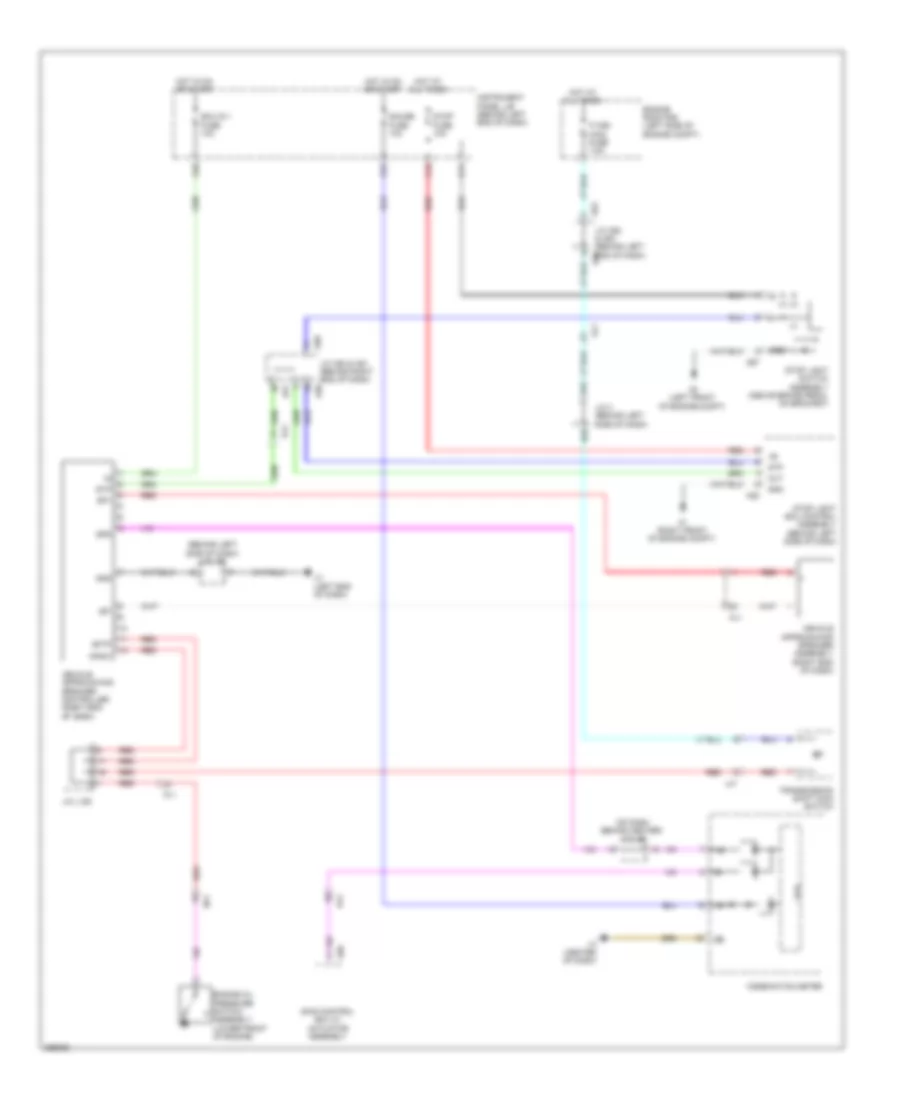
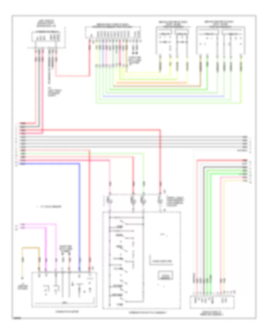
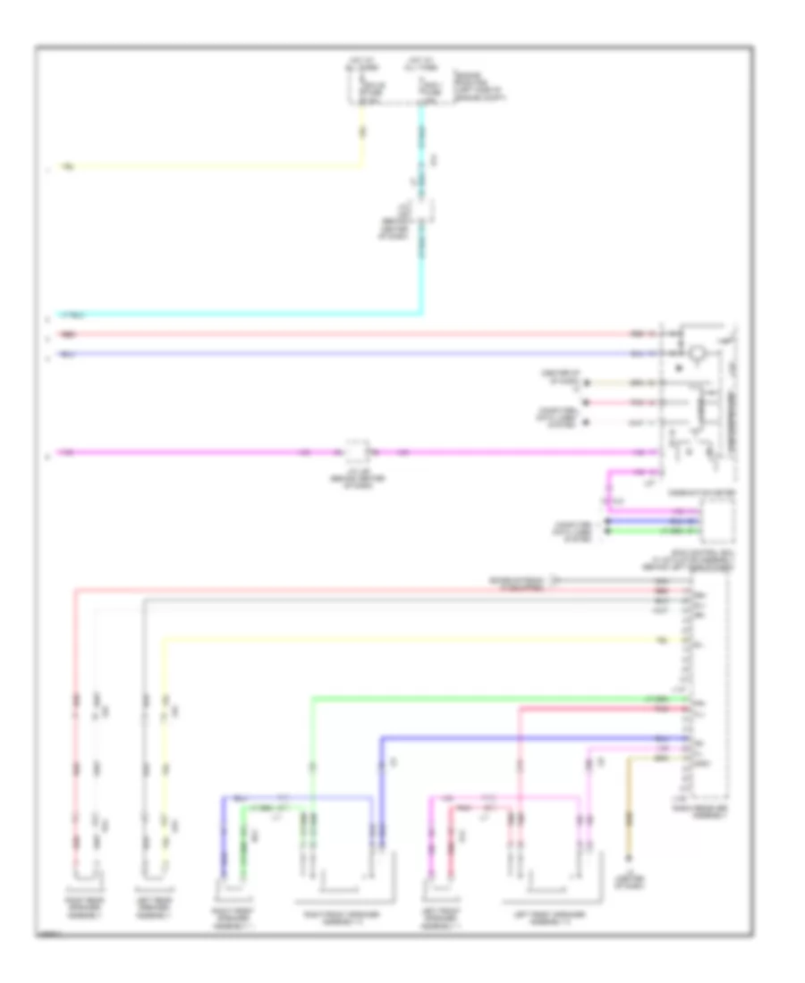
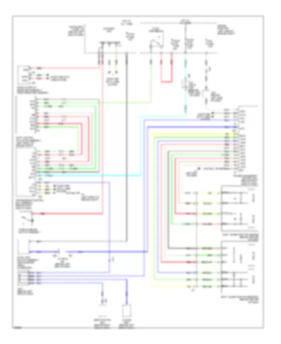
Automatic A/C Wiring Diagram (3 of 3) for Toyota Prius Plug-in 2012
List of elements for Automatic A/C Wiring Diagram (3 of 3) for Toyota Prius Plug-in 2012:
- (left front of engine compt) a4
- (w/ ptc heater)
- A21
- A3 (left front of engine compt)
- A31
- A36
- A37
- A4 (left front of engine compt)
- A52
- A53
- A57
- A59
- Acpb
- Acpe
- Al1
- B71
- C18
- C30
- C31
- Ca1h
- Ca1l
- Can ic
- Canh
- Canl
- Cann
- Canp
- Cds fuse 30a
- Clk
- Combination meter assembly
- Computer data lines system
- Converter inverter assembly
- Cooling fan 2 motor (behind radiator)
- Cooling fan motor (behind radiator)
- Cpu
- D12
- D28
- Da1
- Din
- Dout
- Ecm (left side of engine compt)
- Ecu-b fuse 7.5a
- Ecu-ig 1 fuse 10a
- Efi engine coolant temperature sensor (rear of cylinder head)
- Engine room r/b (left side of engine compt)
- Ethw
- Eti
- Fan relay 1
- Fan relay 2
- Fan relay 3
- Fanh
- Fanl
- Gauge fuse 10a
- Gnd
- Hot at all times
- Hot w/ ig1 relay energized
- I/f
- Idh
- Ig 1
- Ig+
- Instrument panel j/b (behind left end of dash)
- Ite
- J/b 3 (behind left side of dash)
- J/c a52 & a53 (behind left end of dash)
- J/c a56 (behind left end of dash)
- J/c l129
- L2 (left side of dash)
- Motor compressor assembly
- Nca
- Pnk
- Power management control ecu (behind right side of dash)
- Rdi fuse 30a
- Red
- Stb
- Stbi
- Strg
- Thw
- W/ touch sensor
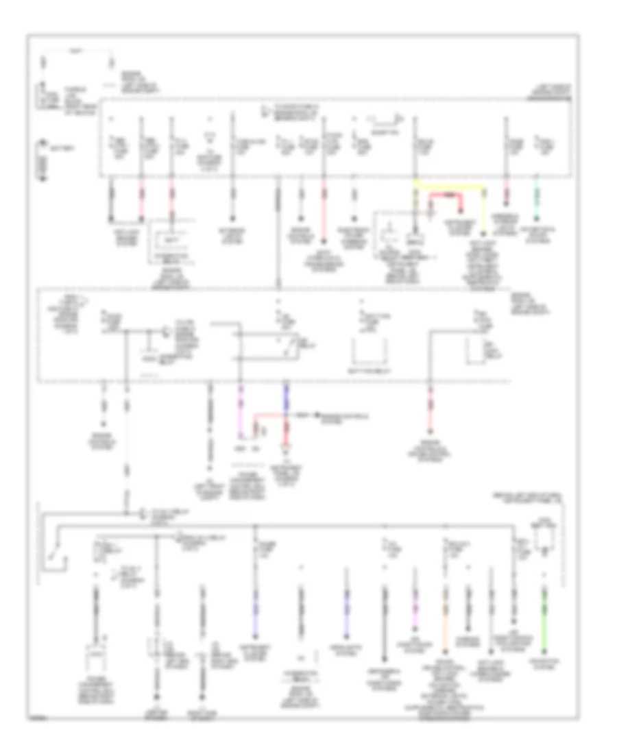
ANTI-LOCK BRAKES
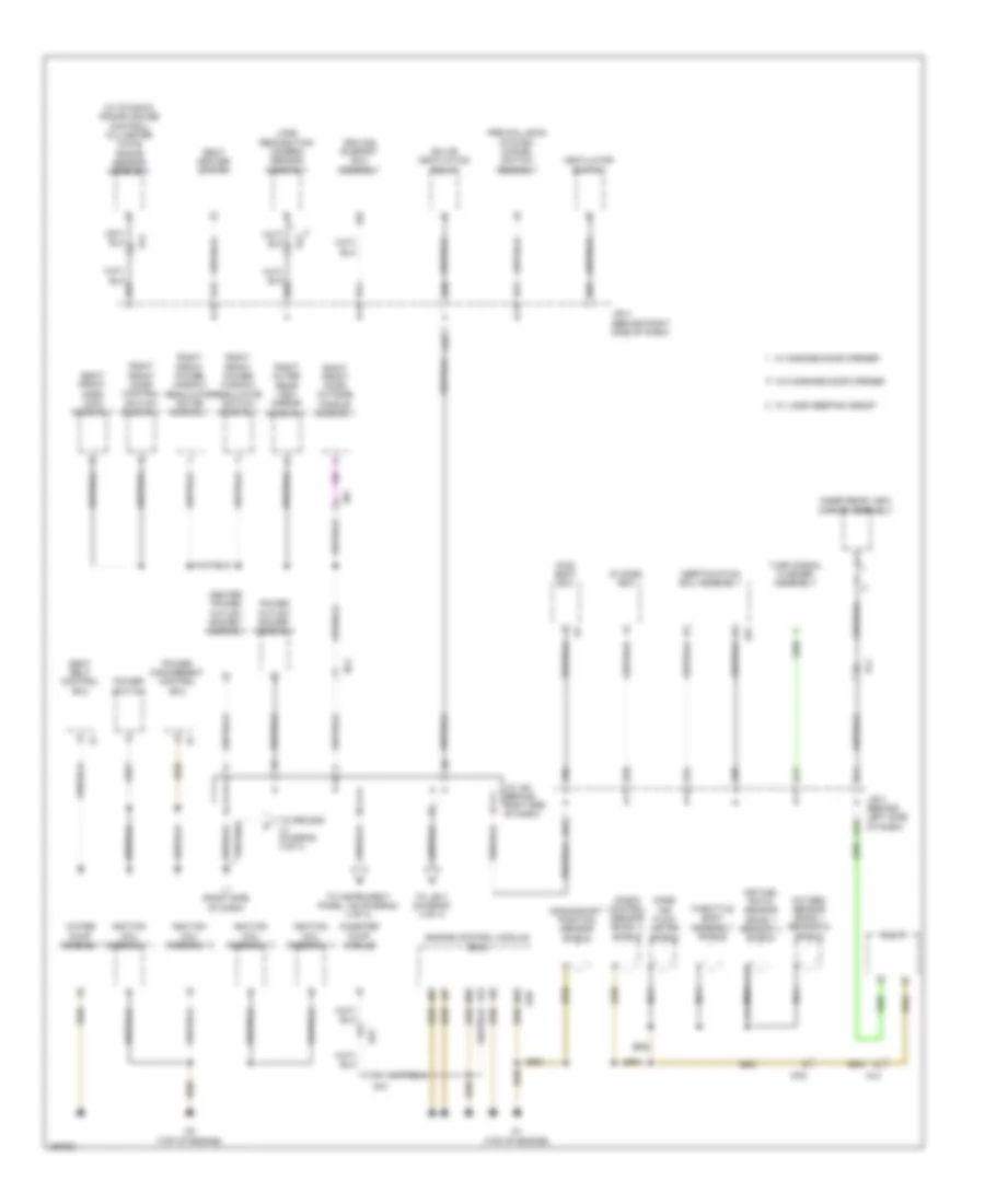
Anti-lock Brakes Wiring Diagram (1 of 2) for Toyota Prius Plug-in 2012
List of elements for Anti-lock Brakes Wiring Diagram (1 of 2) for Toyota Prius Plug-in 2012:
- (left "b" pillar)
- (left side of dash) l2
- A1 (right front of engine compt)
- A16
- A17
- A18
- A21
- A22
- A3 (left front of engine compt)
- A31
- A37
- A4 (left front of engine compt)
- A66
- A67
- A78
- Abs main 1 fuse 20a
- Abs main 2 fuse 7.5a
- Abs mtr 1 fuse 30a
- Abs mtr 2 fuse 30a
- Al1
- Al2
- B16
- B76
- Bat
- Brake booster pump (left rear of
- C18
- C26
- Ca1h
- Ca1l
- Ca2h
- Ca2l
- Can ic
- Canh
- Canl
- Combination meter
- Computer data lines system
- Cpu
- Cty
- Dlc3 (data link connector) (under left side of dash)
- Ecu-b fuse 7.5a
- Ecu-ig2 fuse 10a
- Engine compt)
- Engine room r/b (left side of engine compt)
- Ess
- Exo
- Fl+
- Fl-
- Fr+
- Fr-
- Gauge fuse 10a
- Gnd
- Gnd2
- Gnd3
- Gnd4
- Gnd5
- Gnd6
- Hot at all times
- Hot in on or start
- Hot in run or start
- Hzri
- I/f
- Ig1
- Ig2
- Instrument cluster system
- Instrument panel j/b (behind left end of dash)
- J/b 3 (behind left side of dash)
- J/c a54 (behind right end of dash)
- J/c l129
- J/c l93 (behind right end of dash)
- L1 (right side of dash)
- Lbl
- Left front door courtesy light switch
- Lr1
- Mao2
- Mri1
- Mri2
- Mro1
- Pnk
- Red
- Rl+
- Rl-
- Rr+
- Rr-
- Skg
- Skid control buzzer (behind left side of dash)
- Skid control ecu (behind left side of dash)
- Sks
- Sks2
- Sp1
- Steering sensor (steering column)
- Stp
- Stp2
- Stpo
- Vcsk
- Yaw rate sensor (below center console)
Anti-lock Brakes Wiring Diagram (2 of 2) for Toyota Prius Plug-in 2012
List of elements for Anti-lock Brakes Wiring Diagram (2 of 2) for Toyota Prius Plug-in 2012:
- (behind left end of dash) stop light control relay
- (behind left side of dash) j/b 3
- (behind right end of dash) j/c l93
- (left rear wheel)
- (right rear wheel)
- A1 (right front of engine compt)
- A14
- A20
- A3 (left front of engine compt)
- A50
- A51
- A67
- Acc
- Ar1
- As1
- Becu
- Brake fluid level warning switch (on brake master cylinder reservoir assembly)
- Brake pedal stroke sensor assembly (above brake pedal)
- C11
- C12
- C14
- C18
- C20
- Canh
- Canl
- Computer data lines system
- Dash)
- Ecu-b fuse 7.5a
- Engine room r/b (left side of engine compt)
- Essi
- Gnd
- Gnd1
- Hazard switch
- Hot at all times
- Hot in on or start
- Ign fuse 10a
- Instrument panel j/b (behind left end of dash)
- Integration control & panel assembly
- J/c a50 & a51 (behind left end of dash)
- J/c a56 (behind left end of dash)
- J/c l92 (behind left end of dash)
- L1 (right side of dash)
- L3 (left end of dash)
- Left front speed sensor (left front wheel)
- Left rear speed sensor
- Main body ecu (behind left end of
- Nca
- Out
- Parking brake switch
- Pkb
- Pnk
- Red
- Right front speed sensor (right front wheel)
- Right rear speed sensor
- Skg
- Sks1
- Sks2
- Stop fuse 10a
- Stop light switch (above brake pedal, on bracket)
- Stp
- Vcsk
- Zr2
- Zs2
ANTI-THEFT
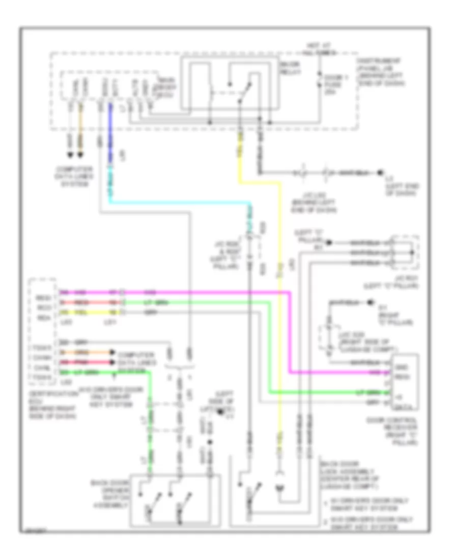
Forced Entry Wiring Diagram (1 of 5) for Toyota Prius Plug-in 2012
List of elements for Forced Entry Wiring Diagram (1 of 5) for Toyota Prius Plug-in 2012:
- (right side of dash) l1
- +b1
- +b2
- A21
- A22
- A3 (left front of engine compt)
- A60
- A67
- Al2
- Am2 fuse 7.5a
- Am21
- Am22
- B10
- B31
- B32
- B33
- Can2h
- Can2l
- Computer data lines system
- E2x1
- E2x2
- Ecu-b fuse 7.5a
- Ecu-b2 fuse 7.5a
- Engine room r/b (left side of engine compt)
- Hall ic
- Hot at all times
- Igct 2 fuse 10a
- Igct fuse 30a
- Igct relay
- Imi
- Imo
- Inds
- Indw
- J/b 3 (behind left side of dash)
- J/c a55 (behind right end of dash)
- J/c a56 (behind left end of dash)
- J/c l93 (behind right end of dash)
- L1 (right side of dash)
- Lin2
- Lb1
- Lz1
- Mrel
- Pnk
- Power management control ecu (behind right side of dash)
- Red
- Shift lever position sensor (behind center of dash)
- Shift lever position sensor 2 (behind center of dash)
- Ssw1
- Ssw2
- Stp
- Transmission shift main switch
- Vcx1
- Vcx2
- Vcx3
- Vcx4
- Vsx1
- Vsx2
- Vsx3
- Vsx4
- W/ id code box
- W/o id code box
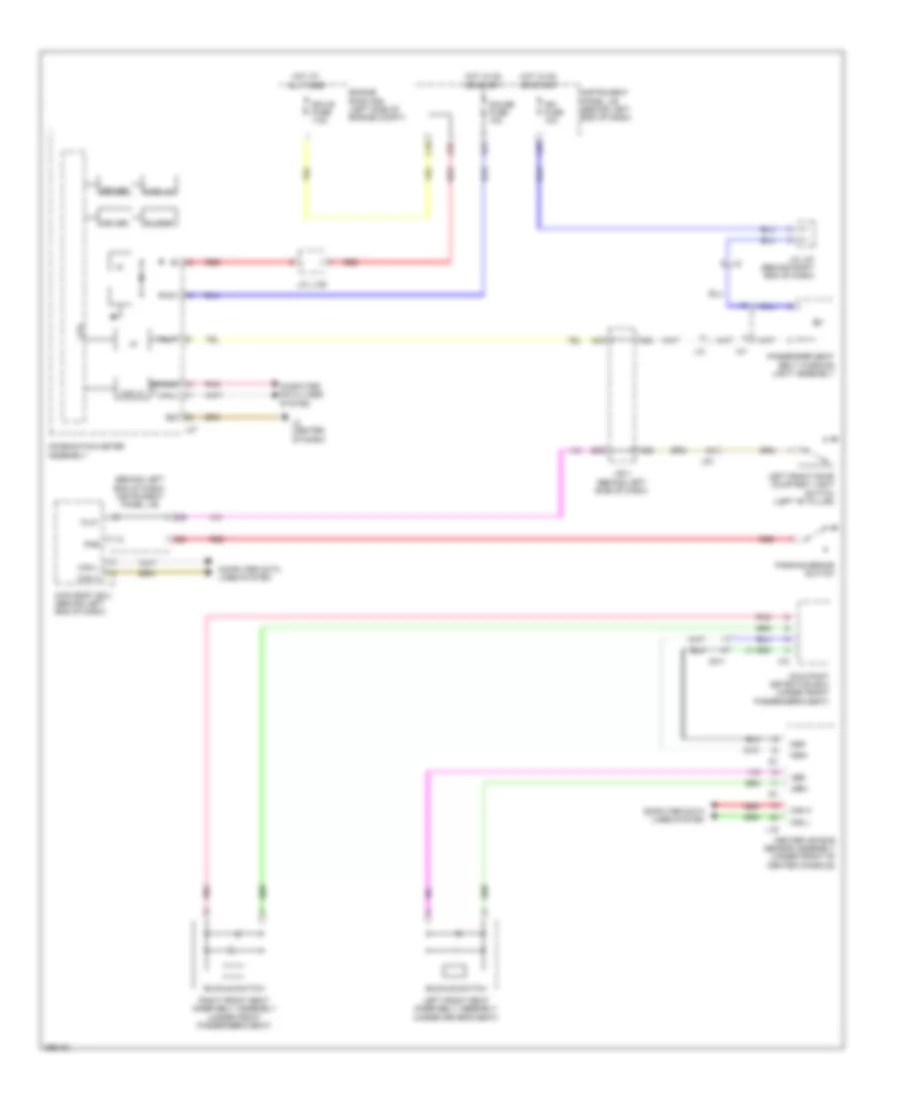
Forced Entry Wiring Diagram (2 of 5) for Toyota Prius Plug-in 2012
List of elements for Forced Entry Wiring Diagram (2 of 5) for Toyota Prius Plug-in 2012:
- (above brake pedal, on bracket) stop light switch
- (behind left end of dash) main body ecu
- A31
- A35
- A37
- A48
- A50
- A59
- A64
- Acc
- Altb
- B25
- B26
- B28
- Becu
- Bk/dr relay
- Buzzer
- C11
- C18
- Can ic
- Canh
- Canl
- Combination meter assembly
- Computer data lines system
- Cpu
- D/l source relay
- Display
- Door fuse 25a
- Driver
- Ecu- acc fuse 10a
- Ecu- ig 1 fuse 10a
- Efii
- Efio
- Gauge fuse 10a
- Gnd
- Gnd1
- Hot at all times
- Hot in on or acc
- Hot in on or start
- I/f
- Id code box (behind left side of dash)
- Ig+
- Instrument panel j/b (behind left end of dash)
- J/b 3 (behind left side of dash)
- J/c a50 & a51 (behind left end of a51 dash)
- J/c l129
- J/c l92 (behind left end of dash)
- J/c l93 (behind right end of dash)
- L1 (right side of dash)
- L2 (center of dash)
- L3 (left end of dash)
- Lin1
- Pnk
- Red
- Security ind
- Stop fuse 10a
- To d/l relay (diagram 3 of 5)
- Tr+
Forced Entry Wiring Diagram (3 of 5) for Toyota Prius Plug-in 2012
List of elements for Forced Entry Wiring Diagram (3 of 5) for Toyota Prius Plug-in 2012:
- (behind left end of dash) main body ecu
- A1 (right front of engine compt)
- A38
- A63
- Act+
- Act-
- Actd
- B10
- B29
- Bzr
- C23
- Canh
- Canl
- Computer data lines system
- D dr unlock relay
- D/l relay
- D11
- D12
- D25
- Dr unlock relay
- From bk/dr a
- From d/l source b
- Haz
- Instrument panel j/b (behind left end of dash)
- J/b 3 (behind left side of dash)
- J/c l89 (behind center of dash)
- L1 (right side of dash)
- L3 (left end of dash)
- Left front door lock motor (rear of driver's door)
- Left rear door lock motor (rear of left rear door)
- Lr1
- Lr2
- Ls1
- Lsr
- Nl1
- Ol1
- Pnk
- Ps1
- Qr1
- R1 (left "c" pillar)
- Red
- Relay (diagram 2 of 5)
- Right front door lock motor (rear of front passenger's door)
- Right rear door lock motor (rear of right rear door)
- S1 (right "c" pillar)
- Turn signal flasher (behind left end of dash)
- Ul3
- Wireless door lock buzzer (left rear of engine compt)
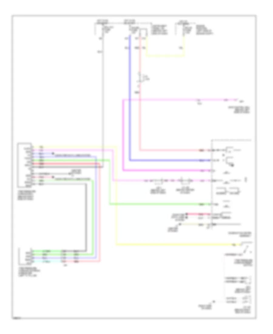
Forced Entry Wiring Diagram (4 of 5) for Toyota Prius Plug-in 2012
List of elements for Forced Entry Wiring Diagram (4 of 5) for Toyota Prius Plug-in 2012:
- (behind left end of dash) main body ecu
- A10
- A14
- A27
- A66
- A72
- Agnd
- B20
- B24
- B46
- B80
- Back door lock assembly (center rear of luggage compt)
- Bcty
- C20
- Code
- Control circuit
- Courtesy
- D fr door fuse 25a
- D35
- D36
- Door lock switch
- Flcy
- Frcy
- Gnd
- Hot at all times
- Inds
- Indw
- Instrument panel j/b (behind left end of dash)
- J/b 3 (behind left side of dash)
- J/c l89 (behind center of dash)
- J/c r28 & r29 (left "c" pillar) r29
- J/c r31 (left "c" pillar)
- L1 (right side of dash)
- L3 (left end of dash)
- Left front door courtesy light switch (left "b" pillar)
- Left rear door courtesy light switch (left "c" pillar)
- Lin1
- Lin2
- Lock
- Lr1
- Lr2
- Lrcy
- Ls1
- Lsfl
- Lsfr
- Multiplex network master switch assembly
- Nl1
- Ol1
- Ol2
- Parking brake switch
- Pkb
- Pnk
- Power switch
- R1 (left "c" pillar)
- R28
- Red
- Right front door control switch assembly
- Right front door courtesy light switch (right "b" pillar)
- Right rear door courtesy light switch (right "c" pillar)
- Ss1
- Ss2
- Swil
- Transponder key coil
- Txct
- Ul1
- Unlock
- Vc5
Forced Entry Wiring Diagram (5 of 5) for Toyota Prius Plug-in 2012
List of elements for Forced Entry Wiring Diagram (5 of 5) for Toyota Prius Plug-in 2012:
- (behind left side of dash) j/b 3
- (front of luggage compt) rear indoor electrical key oscillator
- (right side of luggage compt) indoor luggage compartment electrical key oscillator
- (under center console) front indoor electrical key oscillator
- A32
- A50
- A54
- A55
- A58
- A64
- Agnd
- Ant1
- Ant2
- B73
- B84
- Canh
- Canl
- Certification ecu (behind right side of dash)
- Cg1b
- Cg2b
- Cg5b
- Cg6b
- Cg7b
- Cg8b
- Clg1
- Clg2
- Clg4
- Clg5
- Clg6
- Clg7
- Clg8
- Clgb
- Code
- Computer data lines system
- Cutb
- Data
- Door control receiver (right "c" pillar)
- Efii
- Efio
- Gnd
- Hot in on or start
- Idw
- Ign fuse 10a
- Ind
- Instrument panel j/b (behind left end of dash)
- J/b 3 (behind left side of dash)
- J/c l93 (behind right end of dash)
- J/c s20 (right side of luggage compt)
- L1 (right side of dash)
- L3 (center of dash)
- L62
- L63
- Left front door outside handle assembly
- Lin
- Lr1
- Ls1
- Nl1
- Ol1
- Outside luggage electrical key antenna (driver's door w/o smart key system) (behind center of rear bumper)
- Pnk
- Pos1
- Pos2
- Rco
- Rda
- Red
- Right front door outside handle assembly (w/o driver's door smart key system)
- Rssi
- S1 (right "c" pillar)
- Sen1
- Sen2
- Sens
- Swil
- Trg+
- Trunk, tailgate, fuel doors system
- Tsw1
- Tsw2
- Tsw5
- Tsw6
- Txct
- Vc5
- Zn1
- Zo1
Immobilizer Wiring Diagram for Toyota Prius Plug-in 2012
List of elements for Immobilizer Wiring Diagram for Toyota Prius Plug-in 2012:
- A24
- A49
- A64
- A73
- Al1
- Al2
- B10
- B25
- B26
- B28
- B33
- Certification ecu (behind right side of dash)
- Ecu-b2 fuse 7.5a
- Efii
- Efio
- Engine room r/b (left side of engine compt)
- Gnd
- Hot at all times
- Id code box (behind left side of dash)
- Imi
- Imo
- J/b 3 (behind left side of dash)
- J/c l93 (behind right end of dash)
- L1 (right side of dash)
- L62
- Lin
- Lin1
- Lin2
- Power management control ecu (behind right side of dash)
- Red
- Transmission control ecu (behind right side of dash)
- W/ id code box
- W/o id code box
BODY CONTROL MODULES
Body Control Modules Wiring Diagram for Toyota Prius Plug-in 2012
List of elements for Body Control Modules Wiring Diagram for Toyota Prius Plug-in 2012:
- A24
- A27
- A52
- A57
- A64
- A65
- Acc
- Act+
- Act-
- Actd
- Al3
- Al8
- Altb
- B13
- B17
- B18
- B29
- B31
- Bcty
- Bdsu
- Becu
- Bzr
- C18
- C20
- C22
- C23
- C32
- C35
- C38
- Ca1h
- Ca1l
- Canh
- Canl
- Center air bag sensor assembly (under front of center console)
- Certification ecu (behind right side of dash)
- Cltb
- Clte
- Clts
- Combination meter assembly
- D25
- D26
- D35
- D36
- Dim
- Dlc3 (data link connector) (under left side of dash)
- Door 1 fuse 25a
- Door locks & anti-theft systems
- Drl
- Drle
- Ecm (engine control module) (left side of engine compt)
- Ecu- acc fuse 10a
- Ecu-b fuse 7.5a
- Ecu-ig 1 fuse 10a
- Engine room r/b (left side of engine compt)
- Exterior lights & interior lights systems
- Exterior lights system
- Ffog
- Flcy
- Frcy
- Fspt
- Gnd1
- Gnd2
- Haz
- Hcty
- Head
- Headlights & air conditioning systems
- Headlights system
- Headlights system door locks & anti-theft systems
- Hot at all times
- Hot in on or acc
- Hot in on or start
- Hrly
- Ile
- Instrument cluster, anti-lock brakes & headlights systems
- Instrument panel j/b (behind left end of dash)
- Interior lights system
- J/b 3 (behind left side of dash)
- J/c l92 (behind left end of dash)
- J/c l93 (behind right end of dash)
- J/c l94 (behind left end of dash)
- J/c l95 (behind right side of dash)
- L1 (right side of dash)
- L130
- L149
- L16
- L3 (left end of dash)
- L54
- L62
- Lin2
- Llew
- Lrcy
- Lsfl
- Lsfr
- Lsr
- Main body ecu (behind left end of dash)
- Navigation receiver assembly (w/ navigation) radio & display receiver assembly (w/ radio & display receiver assembly type)
- Pkb ffgo sftp trly
- Pnk
- Power management control ecu (behind right side of dash)
- Power steering ecu (behind left side of dash)
- Power windows & power tops systems
- Power windows system
- Red
- Rlew
- Skid control ecu (behind left side of dash)
- Steering sensor (steering column)
- Tail
- Tr+
- Transmission control ecu (behind right side of dash)
- Trunk, tailgate, fuel doors system
- Ul1
- Ul3
- W/ navigation
- W/ radio & display receiver assembly type
- W/ vehicle proximity notification system
- W/o vehicle proximity notification system
- Yaw rate sensor (below center console)
COMPUTER DATA LINES
Computer Data Lines Wiring Diagram (1 of 2) for Toyota Prius Plug-in 2012
List of elements for Computer Data Lines Wiring Diagram (1 of 2) for Toyota Prius Plug-in 2012:
- (behind left end of dash) j/c l94
- (right side of dash) l1
- +tx1 +tx2
- -tx1 -tx2
- A12
- A16
- A37
- A42
- A46
- A48
- A54
- A64
- A73
- Al2
- Al3
- Al7
- B11
- B96
- Bat
- Ca1h
- Ca1l
- Ca2h
- Ca2l
- Canh
- Canl
- Certification ecu (behind right side of dash)
- Combination meter assembly
- D1 (top of engine)
- Da2
- Dcm (telematics transceiver) (w/ safety connect) (behind center of dash)
- Dlc3 (data link connector 3) (under left side of dash)
- Headlight leveling ecu (behind right end of dash)
- Hot at all times
- Init
- Instrument panel j/b (behind left end of dash)
- J/b 3 (behind left side of dash)
- J/b 4 (behind right side of dash)
- J/c l93 (behind right end of dash)
- L130
- L138
- L143
- L149
- L27
- L54
- L62
- Ls1
- Lvl
- Main body ecu (behind left end of dash)
- Navigation receiver assembly (w/ navigation receiver assembly) radio & display receiver assembly (w/ radio & display receiver assembly)
- Obd fuse 7.5a
- Occupant detection ecu (under front passenger's seat)
- Pnk
- Power steering ecu (behind left side of dash)
- Prst
- Red
- Sil
- Skid control ecu (behind left side of dash)
- Steering sensor (steering column)
- Stereo component amplifier (under driver's seat)
- Sw1
- Tac
- Tire pressure warning ecu (behind right side of dash)
- Tx+
- Tx-
- W/ navigation receiver assembly type
- W/ radio & display receiver assembly type
- W/ separate type amplifier
- Yaw rate sensor (below center console)
Computer Data Lines Wiring Diagram (2 of 2) for Toyota Prius Plug-in 2012
List of elements for Computer Data Lines Wiring Diagram (2 of 2) for Toyota Prius Plug-in 2012:
- (behind center of dash) j/c l102
- (behind right side of dash) j/c l95
- A/c amplifier assembly (behind center of dash)
- A24
- A57
- Al3
- Al4
- Al8
- Ca1h
- Ca1l
- Ca1n
- Ca1p
- Ca2h
- Ca2l
- Ca3n
- Ca3p
- Canh
- Canl
- Cann
- Canp
- Center air bag sensor assembly (under front of center console)
- Driving support ecu (w/ pre- collision system) (behind right side of dash)
- Ecm (left side of engine compt)
- J/c l101 (behind center of dash)
- J/c l92 (behind left end of dash)
- J/c l96,l97,l98 & l99 (behind center of dash)
- L16
- L17
- L3 (left end of dash)
- L96
- L97
- L98
- L99
- Lane recognition camera sensor (w/ lane keeping assist) (center front of roof)
- Millimeter wave radar sensor (w/ pre- collision system) (behind center of front grille)
- Pnk
- Power management control ecu (behind right side of dash)
- Red
- Seat belt control ecu (w/ pre- collision system) (behind right side of dash)
- St-plug
- Tach
- Transmission control ecu (behind right side of dash)
- Ul2
- W/ pre-collision system
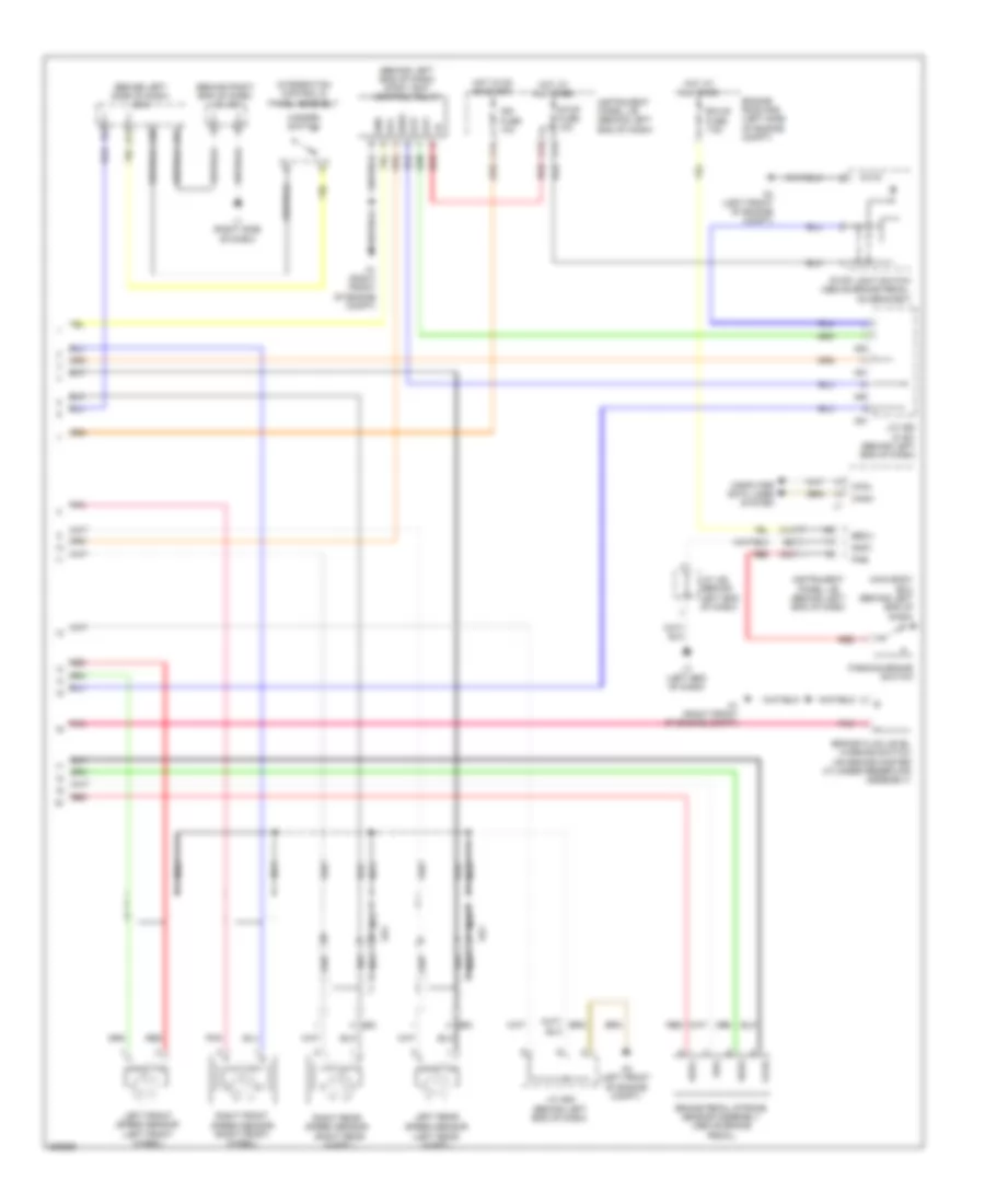
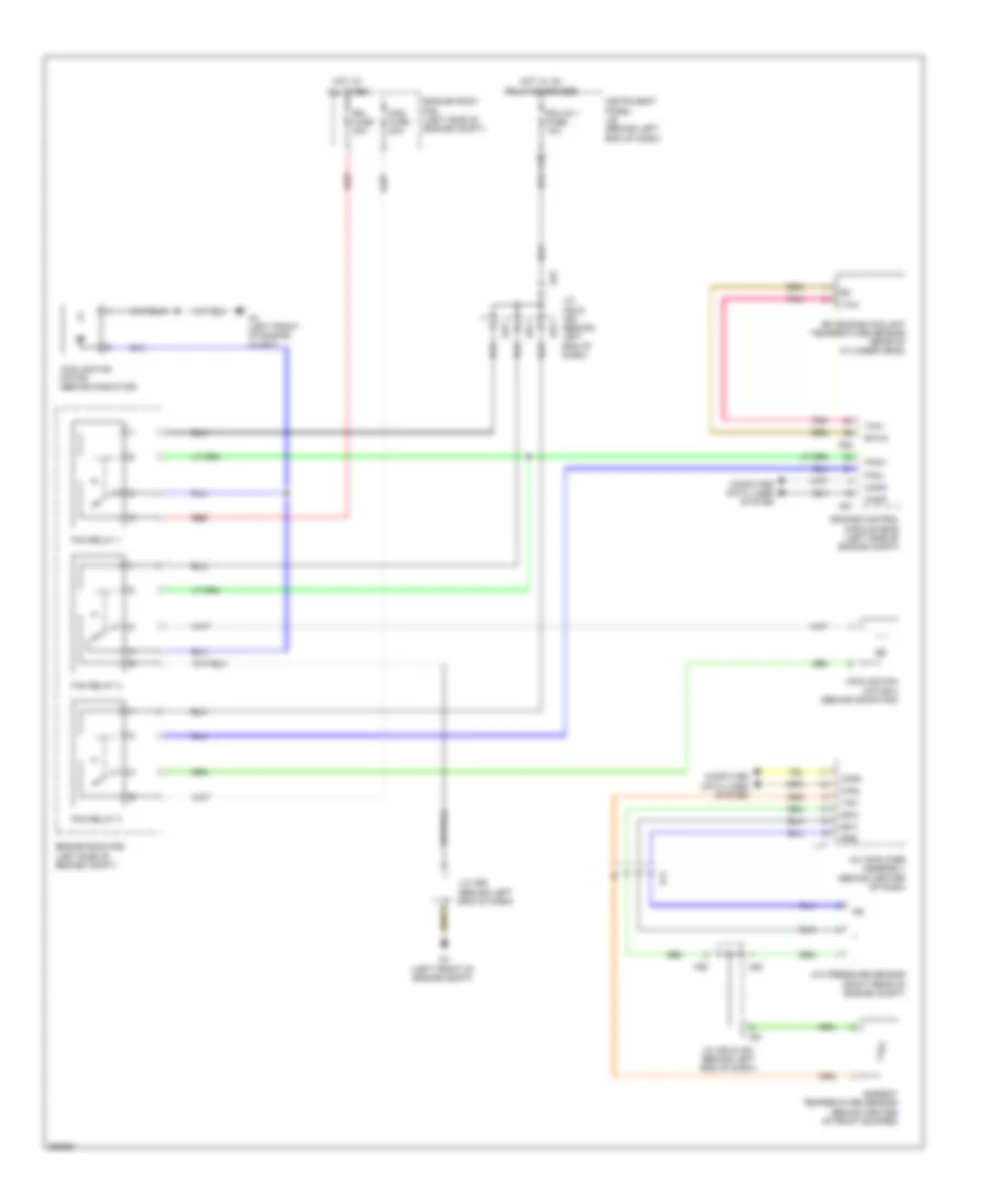
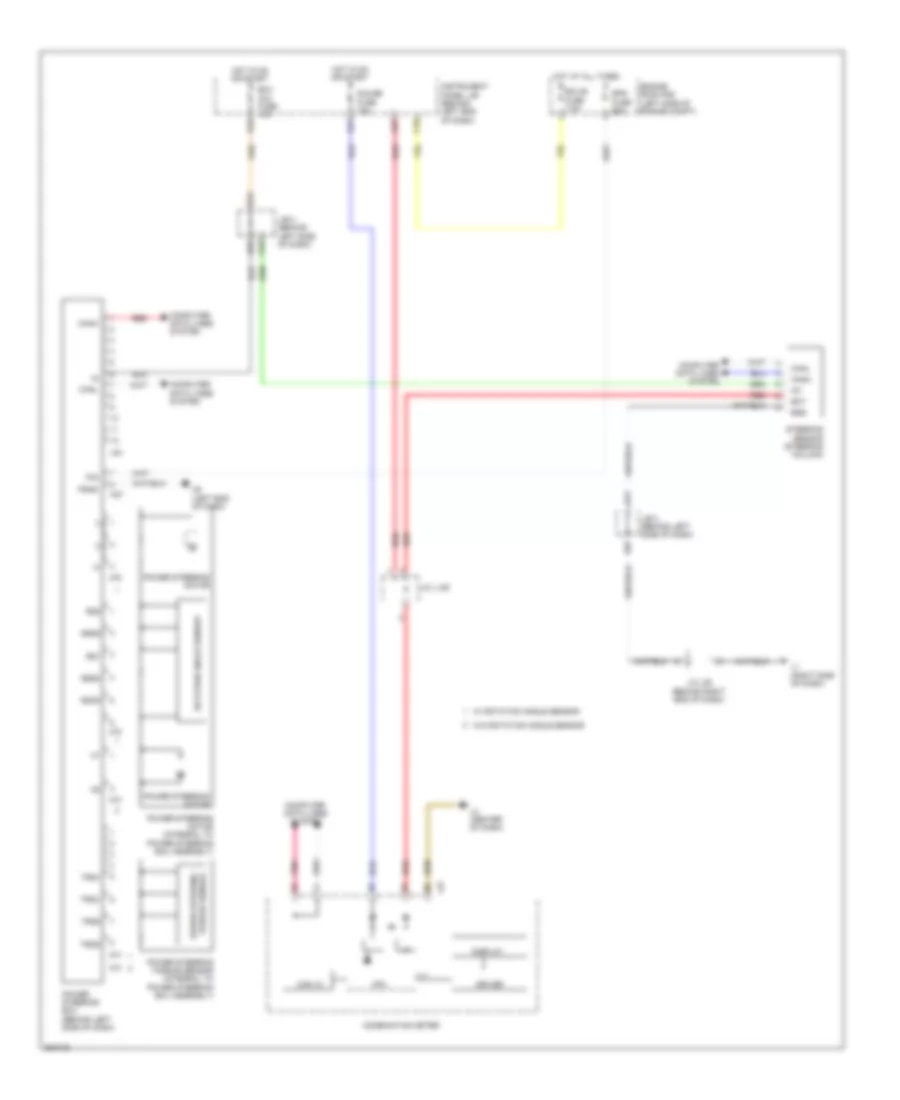
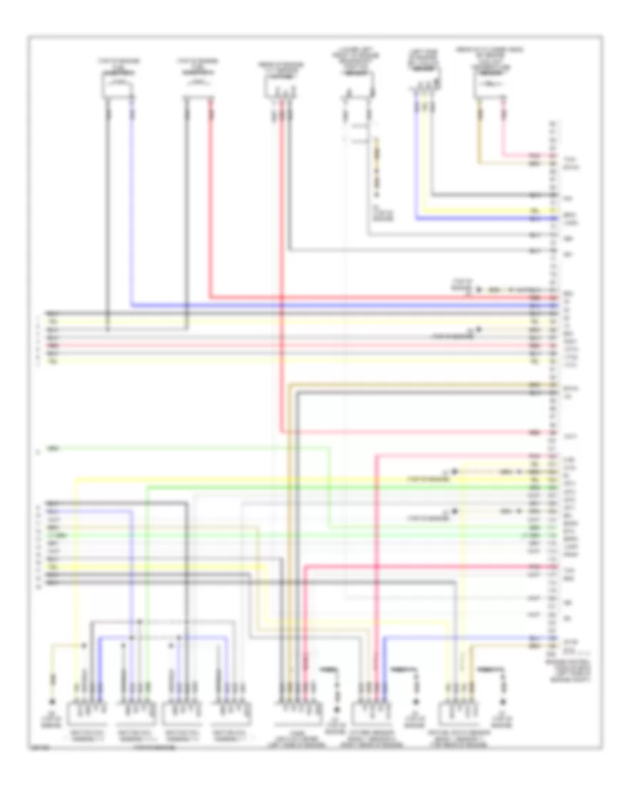
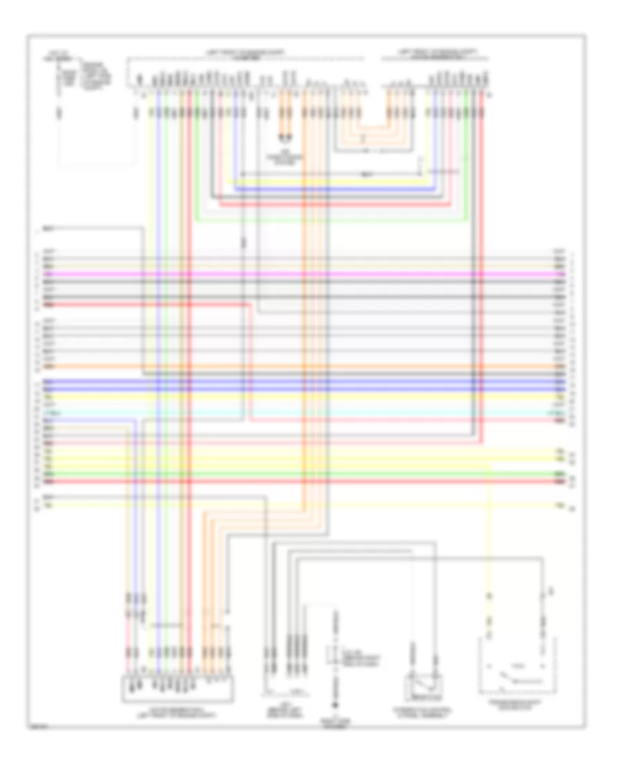
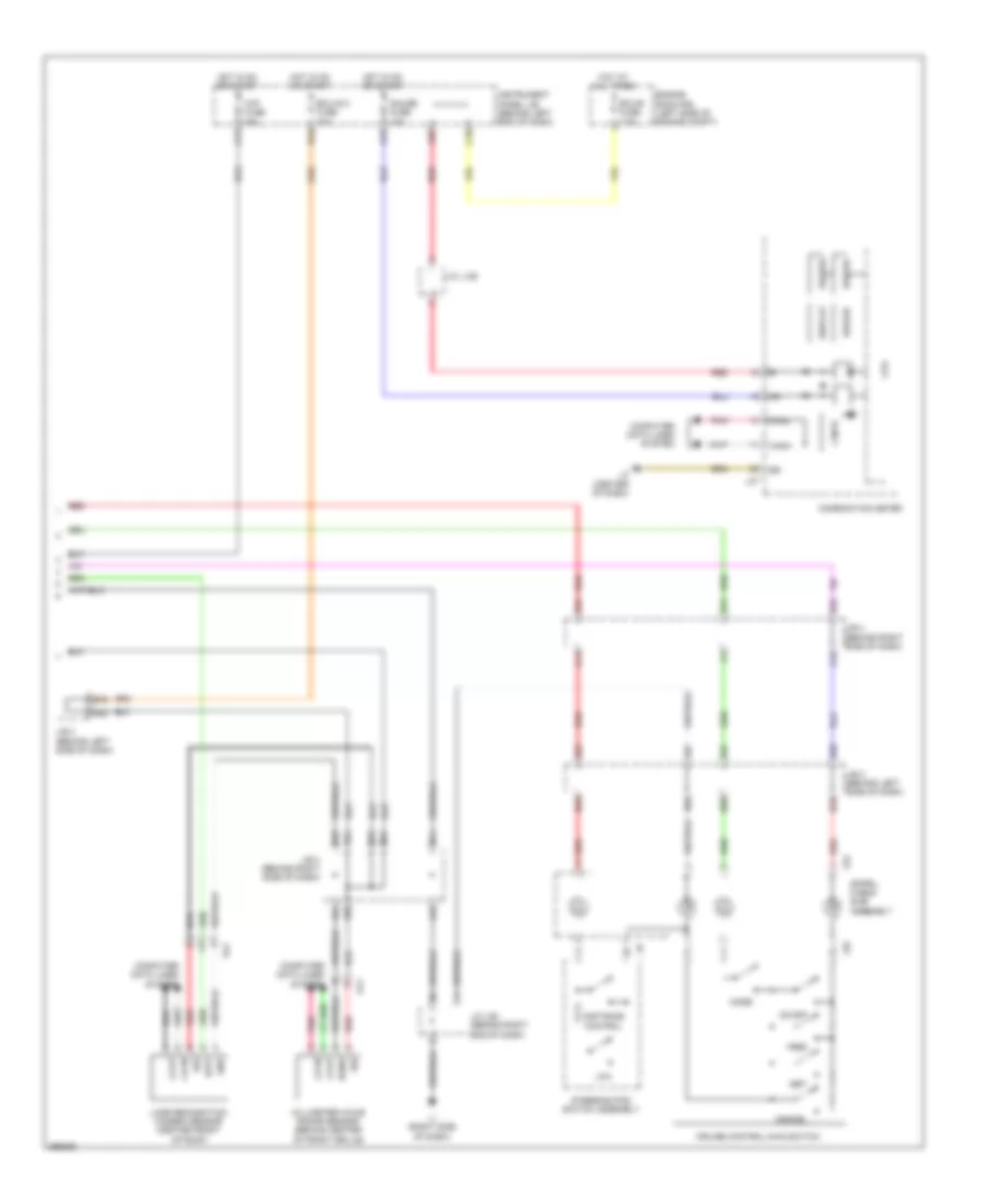
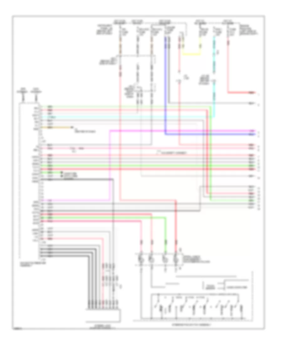
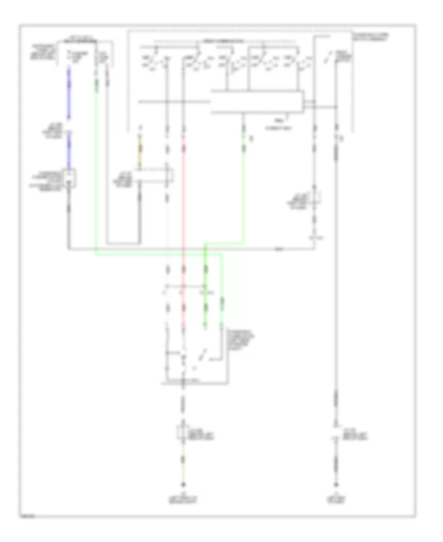
COOLING FAN
Cooling Fan Wiring Diagram for Toyota Prius Plug-in 2012
List of elements for Cooling Fan Wiring Diagram for Toyota Prius Plug-in 2012:
- A/c amplifier assembly (behind center of dash)
- A/c pressure sensor (right rear of engine compt)
- A3 (left front of engine compt)
- A4 (left front of engine compt)
- A50
- A51
- A52
- A53
- A57
- Al1
- Ambient temperature sensor (behind center of front bumper)
- C30
- Canh
- Canl
- Cann
- Canp
- Cds fuse 30a
- Computer data lines system
- Cooling fan motor (behind radiator)
- Cooling fan motor 2 (behind radiator)
- D28
- Ecu-ig 1 fuse 10a
- Efi engine coolant temperature sensor (rear of cylinder head)
- Engine control module (ecm) (left side of engine compt)
- Engine room r/b (left side of engine compt)
- Ethw
- Fan relay 1
- Fan relay 2
- Fan relay 3
- Fanh
- Fanl
- Hot at all times
- Hot w/ ig1 relay energized
- Instrument panel j/b (behind left end of dash)
- J/c a50 & a51 (behind left end of dash)
- J/c a52 & a53 (behind left end of dash)
- J/c a56 (behind left end of dash)
- L17
- Pnk
- Pre
- Rdi fuse 30a
- Red
- S5-3
- Sg-2
- Tam
- Thw
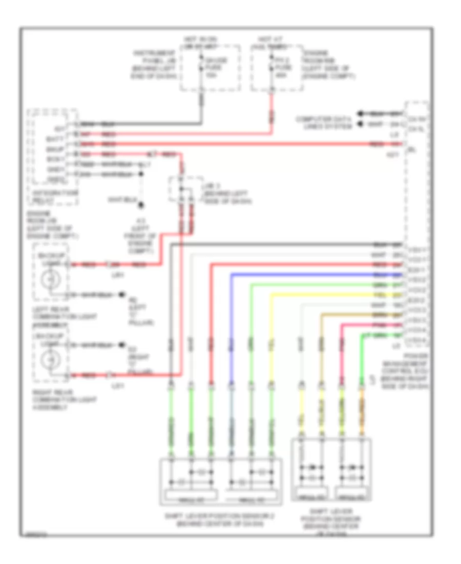
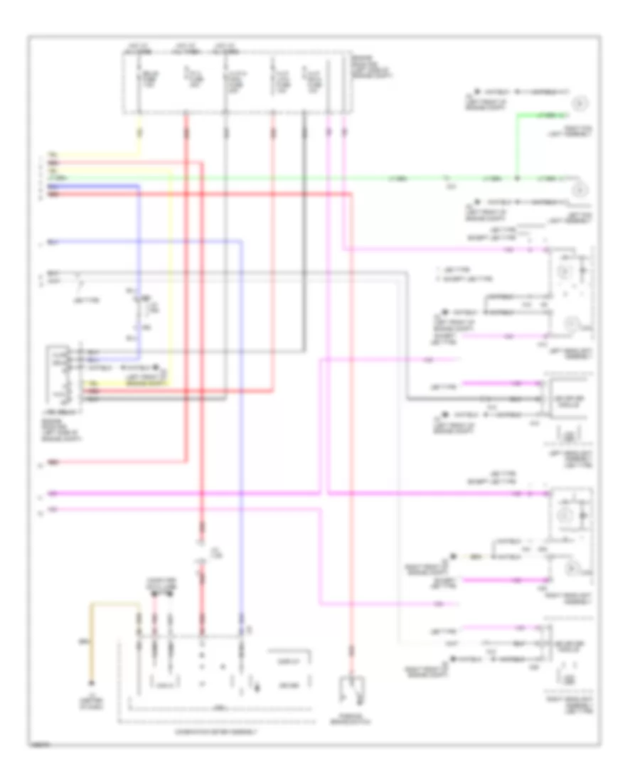
CRUISE CONTROL
Cruise Control Wiring Diagram (1 of 2) for Toyota Prius Plug-in 2012
List of elements for Cruise Control Wiring Diagram (1 of 2) for Toyota Prius Plug-in 2012:
- (behind left end of dash) j/c a50 & a51
- (behind left end of dash) j/c a56
- (left front of engine compt) a3
- A11
- A12
- A3 (left front of engine compt)
- A42
- A50
- A51
- A57
- Al2
- Ar1
- As1
- B73
- B74
- B79
- B83
- Batt
- Brake pedal stroke sensor (w/ dynamic radar cruise control) (above brake pedal)
- Ca1n
- Ca1p
- Ca2h
- Ca2l
- Canh
- Canl
- Cchg
- Ccs
- Computer data lines system
- D1 (top of engine)
- D28
- Driving support ecu (w/ dynamic radar cruise control) (behind right side of dash)
- Ecm (engine control module) (left side of engine compt)
- Efi main fuse 20a
- Efi main relay
- Engine controls system
- Engine room j/b (left side of engine compt)
- Eta
- Fl+
- Fl-
- Fr+
- Fr-
- Ge01
- Gnd
- Hot at all times
- Igb
- J/b 4 (behind right side of dash)
- J/b 4 (w/ dynamic radar cruise control) (behind right side of dash)
- J/c a56 (behind left end of dash)
- J/c l93 (behind right end of dash)
- L1 (right side of dash)
- Left front speed sensor (left front wheel)
- Left rear speed sensor (left rear wheel)
- Mrel
- Nca
- Out
- Pnk
- Red
- Right front speed sensor (right front wheel)
- Right rear speed sensor (right rear wheel)
- Rl+
- Rl-
- Rr+
- Rr-
- Skg
- Skid control ecu (behind left side of dash)
- Sks
- Sks1
- Sks2
- Sp1
- Spsw
- St1-
- Stop light control relay assembly (w/ dynamic radar cruise control) (behind left end of dash)
- Stp
- Stp-
- Stp2
- Throttle body assembly (left side of engine)
- Vcsk
- Vcta
- Vta
- Vta1
- Vta2
- Zr2
- Zs2
Cruise Control Wiring Diagram (2 of 2) for Toyota Prius Plug-in 2012
List of elements for Cruise Control Wiring Diagram (2 of 2) for Toyota Prius Plug-in 2012:
- (above brake pedal, on bracket) stop light switch assembly
- (behind right side of dash) j/b 4
- +res
- -set
- A22
- A24
- A26
- A3 (left front of engine compt)
- A31
- A32
- A42
- A50
- A51
- A54
- A60
- A67
- Accelerator pedal sensor (on accelerator pedal assembly)
- Al2
- Al4
- B12
- B16
- B34
- B52
- B57
- B58
- B64
- B68
- B69
- B70
- B76
- B84
- B88
- C11
- C12
- Ca1n
- Ca1p
- Ca3n
- Ca3p
- Can ic
- Cancel
- Ccs
- Combination meter assembly
- Computer data lines system
- Cpu
- Cruise control main switch
- Display
- Distance control switch
- Driver
- Drn2
- Ecu- ig 2 fuse 10a
- Ep1
- Ep2
- Gauge fuse 10a
- Gnd
- Hot at all times
- Hot in on or start
- I/f
- Igb
- Ign fuse 10a
- Instrument panel j/b (behind left end of dash)
- J/b 3 (behind left side of dash)
- J/b 4 (behind right side of dash)
- J/c a50 & a51 (behind left end of dash)
- J/c l89 (behind center of dash)
- J/c l93 (behind right end of dash)
- L1 (right side of dash)
- L2 (center of dash)
- L27
- L52
- Millimeter wave radar sensor assembly (w/ dynamic radar cruise control) (behind center of front grille)
- Mode
- Nca
- On- off
- Pnk
- Power management control ecu (behind right side of dash)
- Red
- Sgnd
- Spdi
- Spiral cable sub assembly (on steering column)
- St1-
- Steering pad switch assembly
- Stop fuse 10a
- Stp
- Vcp1
- Vcp2
- Vpa1
- Vpa2
- W/ dynamic radar cruise control
- W/o dynamic radar cruise control
- Z10
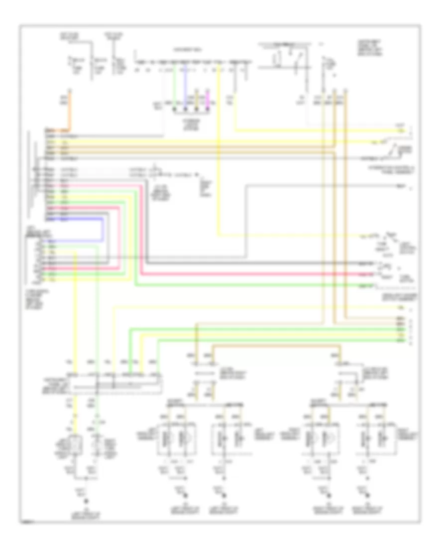
DEFOGGERS
Defoggers Wiring Diagram for Toyota Prius Plug-in 2012
List of elements for Defoggers Wiring Diagram for Toyota Prius Plug-in 2012:
- A/c amplifier assembly (behind center of dash)
- A/c control assembly
- A/c fuse 10a
- A28
- A29
- A3 (left front of engine compt)
- A53
- A67
- A75
- A80
- Al1
- Ar1
- B50
- B55
- B74
- Batt
- C15
- C31
- Canh
- Canl
- Computer data lines system
- Def
- Ecu-b3 fuse 10a
- Engine room j/b (left side of engine compt)
- Engine room r/b (left side of engine compt)
- G14
- G15
- G22
- Gauge fuse 10a
- Gnd
- Gnd1
- Gnd2
- Hot at all times
- Hot w/ ig 1 relay energized
- Ig+
- Ig1
- Instrument panel j/b (behind left end of dash)
- Integration relay
- J/b 3 (behind left side of dash)
- J/c l93 (behind right end of dash)
- L1 (right side of dash)
- L17
- L3 (left end of dash)
- Left outer rear view mirror assembly
- Lin1
- Mhtr
- Mir htr fuse 10a
- Mirror heater
- Nl1
- Noise filter (rear window defogger) (under lower left side of rear window)
- Ol1
- P/i 2 fuse 40a
- Rdef
- Rear window defogger (back door glass)
- Rear window defogger (back window fix glass)
- Rear window defogger switch
- Red
- Right outer rear view mirror assembly
- Tx+
- V1 (left side of liftgate)
- V10
- Vr2
ELECTRONIC POWER STEERING
Electronic Power Steering Wiring Diagram for Toyota Prius Plug-in 2012
List of elements for Electronic Power Steering Wiring Diagram for Toyota Prius Plug-in 2012:
- A16
- A21
- A27
- A31
- A37
- A5 (left end of dash)
- A52
- A67
- B16
- B76
- Bat
- C18
- Can i/c
- Canh
- Canl
- Combination meter
- Computer data lines system
- Cpu
- Display
- Driver
- Ecu ig-2 fuse 10a
- Ecu-b fuse 7.5a
- Engine room r/b (left side of engine compt)
- Eps fuse 60a
- Ess
- Gauge fuse 10a
- Hot at all times
- Hot in on or start
- I/f
- Ig1
- Instrument panel j/b (behind left end of dash)
- J/b 3 (behind left side of dash)
- J/c l129
- J/c l93 (behind right end of dash)
- L1 (right side of dash)
- L2 (center of dash)
- L27
- L54
- Pgnd
- Pig
- Pnk
- Power steering ecu (behind left side of dash)
- Power steering motor
- Power steering motor (integral to power steering ecu assembly)
- Power steering torque sensor (integral to power steering ecu assembly)
- Red
- Rotation angle sensor
- Rzcs
- Rzg
- Rzsn
- Rzv
- Srzg
- Steering sensor (steering column)
- Torque sensor power steering
- Trq1
- Trq2
- Trqg
- Trqv
- W/ rotation angle sensor
- W/o rotation angle sensor
- Z12
- Z13
- Z14
- Z15
- Z16
ENGINE PERFORMANCE
1.8L HYBRID
1.8L Hybrid, Engine Controls Wiring Diagram (1 of 4) for Toyota Prius Plug-in 2012
List of elements for 1.8L Hybrid, Engine Controls Wiring Diagram (1 of 4) for Toyota Prius Plug-in 2012:
- (behind left end of dash) j/c a56
- +b1
- +b2
- +bm
- A13
- A20
- A3 (left front of engine compt)
- A4 (left front of engine compt)
- A57
- A67
- A74
- Al1
- Al2
- Batt
- C/opn relay
- Camshaft timing oil control valve (intake) (front of cylinder head)
- Canh
- Canl
- Cann
- Canp
- Computer data line system
- Computer data lines system
- Cooling fans system
- D2 (top of engine)
- Da2
- Efi 2 fuse 10a
- Efi main fuse 20a
- Efi main relay
- Egr valve (rear of engine)
- Egr1
- Egr2
- Egr3
- Egr4
- Eng w/p fuse 30a
- Eng w/p relay
- Engine control module (ecm) (left side of engine compt)
- Engine room j/b (left side of engine compt)
- Engine room r/b (left side of engine compt)
- Etcs fuse 10a
- Fanh
- Fanl
- Hot at all times
- Ig2 fuse 20a
- Ig2 relay
- Igsw
- Integration control & panel assembly
- J/b 3 (behind left side of dash)
- J/c a56 (behind left end of dash)
- J/c l93 (behind right end of dash)
- L1 (right side of dash)
- Mpmp
- Mrel
- Nwp
- Pgnd
- Pnk
- Pwms
- Pwr mode switch
- Red
- Swp
- Tach
- Vpmp
- Water pump assembly (right front of engine compt)
- Wpi
- Wpo
1.8L Hybrid, Engine Controls Wiring Diagram (2 of 4) for Toyota Prius Plug-in 2012
List of elements for 1.8L Hybrid, Engine Controls Wiring Diagram (2 of 4) for Toyota Prius Plug-in 2012:
- (behind left end of dash) j/c a52
- (near fuel tank) canister pump module
- (top of engine)
- (top of fuel tank) fuel sender gauge assembly
- A44
- Ar1
- As1
- C13
- D1 (top of engine)
- D28
- Da1
- E04
- Egr1
- Egr2
- Egr3
- Egr4
- Engine control module (ecm) (left side of engine compt)
- G2o
- Ge01
- Ha1a
- Hot in on or start
- Ht1b
- Igf
- Ign fuse 10a
- Instrument cluster system
- Instrument panel j/b (behind left end of dash)
- J/c r31 (left "c" pillar)
- Me01
- Met fuse 7.5a
- Mgnd
- Mtrb
- Oc1+
- Oc1-
- Pnk
- Prg
- Pump
- R1 (left "c" pillar)
- Red
- Sgnd
- Vcc
- Vgnd
- Vlvb
- Vout
1.8L Hybrid, Engine Controls Wiring Diagram (3 of 4) for Toyota Prius Plug-in 2012
List of elements for 1.8L Hybrid, Engine Controls Wiring Diagram (3 of 4) for Toyota Prius Plug-in 2012:
- (behind left end of dash) j/c a52 & a53
- (behind right side of dash) power management control ecu
- (left side of engine) throttle body assembly
- (top of engine) fuel injector 1
- (top of engine) fuel injector 2
- A21
- A22
- A52
- A53
- Can ic
- Combination meter assembly
- Computer data lines system
- Cpu
- D1 (top of engine)
- Da2
- Dg1
- Ig2d
- Ind
- Knock control sensor (bank 1) (left side of engine)
- L2 (center of dash)
- Malfunction
- Nca
- Pnk
- Purge vsv (left side of engine)
- Red
- Vta
- Vta2
1.8L Hybrid, Engine Controls Wiring Diagram (4 of 4) for Toyota Prius Plug-in 2012
List of elements for 1.8L Hybrid, Engine Controls Wiring Diagram (4 of 4) for Toyota Prius Plug-in 2012:
- (left side of engine) efi vacuum sensor
- (lower left front of engine) crankshaft position sensor
- (rear of cylinder head) efi engine coolant temperature sensor
- (rear of engine) vvt sensor (intake)
- (top of engine)
- (top of engine) d1
- (top of engine) fuel injector 3
- (top of engine) fuel injector 4
- A1a+
- A1a-
- Air fuel ratio sensor (bank 1 sensor 1) (top rear of engine)
- D1 (top of engine)
- D2 (top of engine)
- D28
- E01
- E02
- E03
- E2g
- Eknk
- Engine control module (ecm) (left side of engine compt)
- Epim
- Eppm
- Eta
- Etha
- Ethw
- G2+
- G2-
- Gnd
- Ha1a
- Ht1b
- Igf
- Ignition coil assembly 1
- Ignition coil assembly 2
- Ignition coil assembly 3
- Ignition coil assembly 4
- Igt1
- Igt2
- Igt3
- Igt4
- Knk1
- Mass air flow meter (left side of engine)
- Nca
- Ne+
- Ne-
- O1b-
- Ox1b
- Oxygen sensor (bank 1 sensor 2) (right rear of engine)
- Pim
- Pnk
- Ppmp
- Red
- Tha
- Thw
- Vcpm
- Vcpp
- Vcta
- Vcv1
- Vta1
- Vta2
- Vvi+
- Vvi-
1.8L Hybrid, Hybrid System Wiring Diagram (1 of 6) for Toyota Prius Plug-in 2012
List of elements for 1.8L Hybrid, Hybrid System Wiring Diagram (1 of 6) for Toyota Prius Plug-in 2012:
- +b2
- A21
- A23
- A26
- A3 (left front of engine compt)
- A31
- A32
- A37
- A52
- A53
- Air conditioning system
- As1
- B12
- B84
- Bk/up
- C11
- C18
- Can ic
- Clk
- Combination meter
- Computer data lines system
- Cpu
- Da1
- Ecu-b fuse 7.5a
- Engine room j/b (left side of engine compt)
- Engine room r/b (left side of engine compt)
- Et1
- Fctl
- G13
- Gauge fuse 10a
- Gmt
- Gmtg
- Hot at all times
- Hot in on or start
- I/f
- Igct 2 fuse 10a
- Igct 3 fuse 10a
- Igct fuse 30a
- Igct relay
- Ign fuse 10a
- Ilk
- Instrument panel j/b (behind left end of dash)
- Integration relay
- Ite
- Iwp
- J/b 3 (behind left side of dash)
- J/c a52 & a53 (behind left end of dash)
- J/c a55 (behind right end of dash)
- J/c a56 (behind left end of dash)
- J/c l129
- J/c l89 (behind center of dash)
- L2 (center of dash)
- Mmt
- Mmtg
- Niwp
- Nodd
- Pcu fuse 10a
- Pnk
- Power management control ecu (behind right side of dash)
- Red
- Sio
- Stb
- Stop fuse 10a
- Transmission control ecu assembly (behind right side of dash)
- Vlo
1.8L Hybrid, Hybrid System Wiring Diagram (2 of 6) for Toyota Prius Plug-in 2012
List of elements for 1.8L Hybrid, Hybrid System Wiring Diagram (2 of 6) for Toyota Prius Plug-in 2012:
- (behind right side of dash) certification ecu
- +bwp
- A3 (left front of engine compt)
- A4 (left front of engine compt)
- Ag1
- Da2
- Engine room j/b (left side of engine compt)
- Gnd
- Hall ic
- Hot at all times
- Hv battery thermometer (right rear of luggage compt)
- Ig2 fuse 20a
- Ig2 relay
- Inverter water pump motor (left front of engine compt)
- L1 (right side of dash)
- L62
- Ls1
- Nwp
- Pnk
- Power switch
- Red
- Shift lever position sensor 2 (behind center of dash)
- Ss1
- Ss2
- Swil
- Swp
1.8L Hybrid, Hybrid System Wiring Diagram (3 of 6) for Toyota Prius Plug-in 2012
List of elements for 1.8L Hybrid, Hybrid System Wiring Diagram (3 of 6) for Toyota Prius Plug-in 2012:
- (right "c" pillar) s1
- +b2
- A4 (left front of engine compt)
- A59
- Abfs
- Air conditioning system
- Am22
- As1
- Bth+
- Bth-
- Ca2h
- Ca2l
- Clk+
- Clk-
- Computer data lines system
- Dc/dc-s fuse 5a
- Drn1
- Drn2
- Drn3
- Drn4
- Drn5
- Drn8
- E01
- E2x1
- E2x2
- Engine room r/b (left side of engine compt)
- Ethb
- Evsw
- Gnd
- Gnd1
- Gnd2
- Hall ic
- Hot at all times
- Hsdn
- Htm+
- Htm-
- Idh
- Igct
- Ilk
- Ilk1
- Ilko
- Inds
- Indw
- Inter lock switch (right side of luggage comp)
- Inverter (left front of engine compt)
- J/c s20 (right side of luggage compt)
- L1 (right side of dash)
- L3 (left end of dash)
- Lz1
- Mth+
- Mth-
- Nodd
- Pnk
- Power management control ecu (behind right side of dash)
- Red
- Req+
- Req-
- Shift lever position sensor (behind center of dash)
- Smrb
- Smrg
- Smrp
- Spdi
- Ssw1
- Sc1
- Thb
- Vcx1
- Vcx2
- Vcx3
- Vcx4
- Vlo
- Vsx1
- Vsx2
- Vsx3
- Vsx4
1.8L Hybrid, Hybrid System Wiring Diagram (4 of 6) for Toyota Prius Plug-in 2012
List of elements for 1.8L Hybrid, Hybrid System Wiring Diagram (4 of 6) for Toyota Prius Plug-in 2012:
- (left front of engine compt) inverter
- (left front of engine compt) motor generator 1
- A11
- A20
- A23
- A67
- Acpb
- Acpe
- Air conditioning system
- Amd
- B31
- Cbi
- Cei
- D29
- Da1
- Dc/dc fuse 125a
- Drn6
- Engine room j/b (left side of engine compt)
- Ev switch
- Gcs
- Gcsg
- Gmt
- Gmtg
- Grf
- Grfg
- Gsn
- Gsng
- Hot at all times
- Integration control & panel assembly
- J/b 3 (behind left side of dash)
- J/c l93 (behind right end of dash)
- L1 (right side of dash)
- Lb1
- Mcs
- Mcsg
- Mmt
- Mmtg
- Motor generator 2 (left front of engine compt)
- Mrf
- Mrfg
- Mscg
- Msn
- Msng
- Nca
- Red
- Transmission shift main switch
1.8L Hybrid, Hybrid System Wiring Diagram (5 of 6) for Toyota Prius Plug-in 2012
List of elements for 1.8L Hybrid, Hybrid System Wiring Diagram (5 of 6) for Toyota Prius Plug-in 2012:
- (right side of luggage compt) j/c s20
- As1
- Batt fan fuse 10a
- Batt fan relay
- Battery cooling blower assembly (right side of luggage compt)
- Battery voltage sensor
- Bth+
- Bth-
- Busbar module 1
- Busbar module 2
- Current sensor
- Engine room j/b (left side of engine compt)
- Gb0
- Gb1
- Gb2
- Gc0
- Gib
- Gnd
- Gnd0
- Hot at all times
- Hv battery junction block (right side of luggage compt)
- Hybrid vehicle battery
- Ig0
- Igct
- J/c s20 (right side of luggage compt)
- Ls1
- Main relay
- Pnk
- Pnk vb4
- Precharge relay
- Red
- Red gb0
- Red vb12
- S1 (right "c" pillar)
- Service plug
- Si0
- Sc1
- Tb0
- Tb1
- Tb2
- Tc0
- Vb2
- Vb5
- Vc1 j1
- Vc10
- Vc11
- Vc12
- Vc13
- Vc14
- Vc2
- Vc3
- Vc4
- Vc5
- Vc6
- Vc7
- Vc8
- Vc9
- Vib
- Vm0
- Z17
1.8L Hybrid, Hybrid System Wiring Diagram (6 of 6) for Toyota Prius Plug-in 2012
List of elements for 1.8L Hybrid, Hybrid System Wiring Diagram (6 of 6) for Toyota Prius Plug-in 2012:
- (left side of engine compt) engine control module (ecm)
- (top of engine) d2
- +b1
- A22
- A3 (left front of engine compt)
- A50
- A51
- Accd
- Accelerator pedal sensor (on accelerator pedal assembly)
- Al2
- Am2 fuse 7.5a
- Am21
- Anti-theft system
- B32
- Ca1h
- Ca1l
- Ca3n
- Ca3p
- Ccs
- Clk+
- Clk-
- Computer data lines system
- Cruise control system
- D28
- Da2
- Drn2
- E02
- Engine room r/b (left side of engine compt)
- Ep1
- Ep2
- Exterior light system
- G2o
- Gnd
- Hot at all times
- Hsdn
- Htm+
- Htm-
- Ig1d
- Ig2
- Ig2d
- Igf
- Ignition coil 1 (top of engine)
- Ignition coil 2 (top of engine)
- Ignition coil 3 (top of engine)
- Ignition coil 4 (top of engine)
- Igt1
- Igt2
- Igt3
- Igt4
- Imi
- Imo
- J/b 3 (behind left side of dash)
- J/c a50 & a51 (behind left end of dash)
- J/c a50 & a51 (behind left end of dash) a50
- L3 (left end of dash)
- Lin2
- Mrel
- Mth+
- Mth-
- Nca
- Pcon
- Power distribution system
- Power management control ecu (behind right side of dash)
- Ppos
- Red
- Req+
- Req-
- Skid control ecu (behind left side of dash)
- Ssw2
- St1-
- Stop light switch (above brake pedal, on bracket)
- Stp
- Transmissions system
- Vcp1
- Vcp2
- Vpa1
- Vpa2
EXTERIOR LIGHTS
Backup Lamps Wiring Diagram for Toyota Prius Plug-in 2012
List of elements for Backup Lamps Wiring Diagram for Toyota Prius Plug-in 2012:
- A21
- A3 (left front of engine compt)
- A53
- A77
- Al1
- Assembly
- B16
- Backup light
- Batt
- Bck1
- Bkup
- C31
- Ca1h
- Ca1l
- Computer data lines system
- E2x1
- E2x2
- Engine room j/b (left side of engine compt)
- Engine room r/b (left side of engine compt)
- G13
- G14
- G22
- Gauge fuse 10a
- Gnd1
- Gnd2
- Hall ic
- Hot at all times
- Hot in on or start
- Ig1
- Instrument panel j/b (behind left end of dash)
- Integration relay
- J/b 3 (behind left side of dash)
- Left rear combination light
- Lr1
- Ls1
- Lz1
- P/i 2 fuse 40a
- Pnk
- Power management control ecu (behind right side of dash)
- R2 (left "c" pillar)
- Red
- Right rear combination light assembly
- S2 (right "c" pillar)
- Shift lever position sensor (behind center of dash)
- Shift lever position sensor 2 (behind center of dash)
- Vcx1
- Vcx2
- Vcx3
- Vcx4
- Vsx1
- Vsx2
- Vsx3
- Vsx4
Exterior Lamps Wiring Diagram (1 of 2) for Toyota Prius Plug-in 2012
List of elements for Exterior Lamps Wiring Diagram (1 of 2) for Toyota Prius Plug-in 2012:
- A10
- A11
- A14
- A16
- A17
- A2 (right front of engine compt)
- A20
- A22
- A3 (left front of engine compt)
- A36
- A37
- A38
- A39
- A40
- A41
- A42
- A46
- A47
- A50
- A51
- A56
- A61
- A64
- A65
- A67
- A68
- A71
- Acc
- Auto
- B16
- B41
- B76
- Bcty
- Becu
- C10
- C17
- C18
- C36
- Ca1
- D17
- D18
- D35
- D36
- Ecu- acc fuse 10a
- Ecu-ig fuse 10a
- Except led type
- Flcy
- Frcy
- Gnd
- Haz
- Hazard switch
- Head
- Headlight dimmer switch assembly
- Hot in on or acc
- Hot in on or start
- Instrument panel j/b (behind left end of dash)
- Integration control & panel assembly
- Interior lights system
- J/b 3 (behind left side of dash)
- J/c a50 & a51 (behind left end of dash)
- J/c a54 (behind right end of dash)
- J/c l93 (behind right end of dash)
- L1 (right side of dash)
- Led type
- Left
- Left front turn signal light
- Left headlight assembly
- Light control switch
- Lrcy
- Main body ecu
- Marker
- Off
- Parking
- Pnk
- Right
- Right front turn signal light
- Right headlight assembly
- Tail
- Tail fuse 10a
- Tail relay
- Trly
- Turn signal flasher (behind left end of dash)
- Turn switch
Exterior Lamps Wiring Diagram (2 of 2) for Toyota Prius Plug-in 2012
List of elements for Exterior Lamps Wiring Diagram (2 of 2) for Toyota Prius Plug-in 2012:
- (center of dash) l2
- A1 (right front of engine compt)
- A22
- A3 (left front of engine compt)
- A50
- A51
- Acc
- Al2
- Al4
- Anti-lock brakes system
- Ar1
- As1
- Backup
- Backup lamps circuit
- C11
- C12
- Can ic
- Center stop light assembly
- Combination meter assembly
- Computer data lines system
- Cpu
- Cruise control system
- Dc/dc fuse 125a
- Driving support ecu (behind right side of dash)
- Ecu-b fuse 7.5a
- Engine room j/b (left side of engine compt)
- Engine room r/b (left side of engine compt)
- Essi
- Gnd
- Hot at all times
- Instrument panel j/b (behind left end of dash)
- J/c a50 & a51 (behind left end of dash)
- J/c r28 & r29 (left "c" pillar)
- L27
- Left license plate light assembly
- Left rear combination light assembly
- Left turn ind
- Lr1
- Ls1
- Marker
- Out
- Pnk
- Power management control ecu (behind right side of dash)
- R2 (left "c" pillar)
- R28
- R29
- Red
- Right license plate light assembly
- Right rear combination light assembly
- Right turn ind
- S2 (right "c" pillar)
- Skid control ecu (behind left side of dash)
- Stop fuse 10a
- Stop light control relay (behind left end of dash)
- Stop light switch (above brake pedal on bracket)
- Stop/tail
- Stp
- Stp-
- Turn
- Turn & haz fuse 10a
- V1 (left side of liftgate)
- Vehicle approaching speaker controller (right end of dash)
- Vr1
- Dv1
GROUND DISTRIBUTION
Ground Distribution Wiring Diagram (1 of 4) for Toyota Prius Plug-in 2012
List of elements for Ground Distribution Wiring Diagram (1 of 4) for Toyota Prius Plug-in 2012:
- (except led type) right headlight assembly
- (led type) right headlight assembly
- (w/ navigation) radio & display receiver assembly (w/o navigation) radio receiver assembly
- (w/ safety connect system) dcm (telematics transceiver)
- (w/ separate type amplifier) stereo component amplifier assembly
- (w/o navigation) radio & display receiver assembly
- A1 (right front of engine compt)
- A2 (right front of engine compt)
- A38
- A39
- A40
- A41
- A42
- A46
- Back door lock assembly
- Back door opener switch assembly
- Brake fluid level warning switch (brake master cylinder reservoir assembly)
- Center stop light assembly
- Combination meter assembly
- Engine hood courtesy switch assembly
- Fuel sender gauge assembly
- Headlight cleaner relay
- J/c l85 (behind center of dash)
- J/c r31 (left "c" pillar)
- J/c x9
- L127
- L138
- L142
- L143
- L146
- L2 (center of dash)
- L27
- Left front power seat switch
- Left license plate light assembly
- Left rear combination light assembly
- Left rear door w/ motor lock assembly
- Left rear power window regulator motor assembly
- Left rear power window regulator switch assembly
- Left seat heater control sub-assembly
- Navigation receiver assembly
- Qr1
- R1 (left "c" pillar)
- R2 (left "c" pillar)
- Rear window defogger (back door glass)
- Rear window defogger (back window fix glass)
- Rear wiper motor assembly
- Right license plate light assembly
- Rx2
- Skid control ecu w/ actuator assembly
- Stop light control relay assembly
- Tire pressure warning ecu
- V1 (left side of liftgate)
- V10
- Vr2
- W/ built in type amplifier
- W/ navigation receiver assembly type
- W/ radio & display receiver assembly type
- W/ radio receiver assembly type
- W/ separate type amplifier
- Wireless door lock buzzer
- Dv1
Ground Distribution Wiring Diagram (2 of 4) for Toyota Prius Plug-in 2012
List of elements for Ground Distribution Wiring Diagram (2 of 4) for Toyota Prius Plug-in 2012:
- (except led type) left headlight assembly
- (led type) left headlight assembly
- (left side of engine compt) engine room j/b
- (left side of engine compt) engine room r/b
- (w/ ptc heater) quick heater assembly
- A10
- A11
- A12
- A13
- A16
- A17
- A18
- A20
- A24
- A27
- A3 (left front of engine compt)
- A4 (left front of engine compt)
- A5 (left end of dash)
- A57
- A59
- A6 (right end of dash)
- Ag1
- Brake booster pump assembly
- Ca1
- Canada
- Cooling fan motor
- D12
- Da1
- Drl relay
- Efi main relay
- Eng w/p relay
- Engine control module (ecm)
- Fan relay 2
- G22
- Headlight leveling ecu assembly
- Ig2 relay
- Igct relay
- Integration relay
- Inverter water pump motor assembly
- J/c a56 (behind left end of dash)
- Left fog light assembly
- Left front speed sensor shield
- Left front turn signal light
- Left rear speed sensor shield
- Nca
- P-con mtr relay
- Power steering ecu assembly
- Right fog light assembly
- Right front speed sensor shield
- Right front turn signal light
- Right rear speed sensor shield
- Skid control ecu w/ actuator assembly
- Stop light switch assembly
- Transmission control ecu assembly
- Usa
- W/ converter inverter assembly
- W/ motor compressor assembly
- Windshield wiper motor assembly
Ground Distribution Wiring Diagram (3 of 4) for Toyota Prius Plug-in 2012
List of elements for Ground Distribution Wiring Diagram (3 of 4) for Toyota Prius Plug-in 2012:
- (w/ dynamic radar cruise control) millimeter wave radar sensor assembly
- A41
- A42
- A54
- A55
- A64
- A65
- Air fuel ratio sensor (bank 1 sensor 1) shield
- Al2
- Al4
- As1
- B14
- B15
- B27
- B28
- B52
- B74
- B75
- Canister pump module
- Center power outlet socket assembly
- Certification ecu assembly
- Crankshaft position sensor shield
- D1 (top of engine)
- D2 (top of engine)
- D28
- Da1
- Da2
- Dlc 3
- Driving support ecu assembly
- Engine control module (ecm)
- Id code box
- Ignition coil assembly 1
- Ignition coil assembly 2
- Ignition coil assembly 3
- Ignition coil assembly 4
- Inner rear view mirror assembly
- J/b 3 (behind left side of dash)
- J/b 4 (behind right side of dash)
- J/c l93 (behind right end of dash)
- Knock control sensor (bank 1) shield
- L1 (right side of dash)
- L62
- Lane recognition camera sensor assembly
- Main body ecu
- Mass air flow meter shield
- Nca
- Nl2
- Oxygen sensor (bank 1 sensor 2) shield
- Power management control ecu
- Power outlet socket assembly
- Power switch
- Pre-collision system cancel switch assembly
- Right front door control switch assembly
- Right front door lock assembly
- Right front door outside handle assembly
- Right front power window regulator motor assembly
- Right front power window regulator switch assembly
- Right outer rear view mirror assembly
- Seat belt control ecu
- Seat heater switch
- Solar ventilation relay
- Throttle body assembly shield
- To ground l3 (diagram 4 of 4)
- To instrument panel j/b (diagram 4 of 4)
- To j/b 3 (diagram 4 of 4)
- Turn signal flasher assembly
- Ul1
- Ul2
- Ventilator switch
- W/ garage door opener
- W/ lane keeping assist
- W/o garage door opener
- Water pump assembly
- Zn1
Ground Distribution Wiring Diagram (4 of 4) for Toyota Prius Plug-in 2012
List of elements for Ground Distribution Wiring Diagram (4 of 4) for Toyota Prius Plug-in 2012:
- (behind left end of dash) instrument panel j/b
- (w/ pre-collision system) junction connector
- A/c amplifier assembly
- A/c control assembly
- A20
- A21
- A22
- A24
- A25
- A32
- A33
- A67
- A68
- A69
- A80
- Acc relay
- B17
- B19
- B31
- B43
- B44
- B55
- B68
- Battery cooling blower assembly
- Battery voltage sensor
- Bk/dr relay
- Center air bag sensor assembly
- Combination meter assembly
- Cruise control main switch
- D dr unlock relay
- D/l relay
- Door control receiver
- Dr unlock relay
- From ground c l1 (diagram 3 of 4)
- From j/c l93 (diagram 3 of 4)
- Front blower w/ fan motor sub-assembly
- Glove box light assembly (interior illumination light assembly 1)
- Headlight dimmer switch assembly
- Hv battery junction block assembly
- Ig1 1 relay
- Ig1 2 relay
- Ig1 3 relay
- Im1
- Integration control & panel assembly
- Inter lock switch
- J/b 3 (behind left side of dash)
- J/c l92 (behind left end of dash)
- J/c s20 (right side of luggage compt)
- L137
- L16
- L17
- L3 (left end of dash)
- L49
- L52
- L96
- Left front door lock assembly
- Left front door outside handle assembly
- Left front power window regulator motor assembly
- Left outer rear view motor assembly
- Left visor assembly
- Li2
- Lr1
- Lb1
- Main body ecu
- Map light assembly
- Multiplex network master switch assembly
- Occupant detection ecu
- Ol2
- Outer mirror switch assembly
- P/point relay
- Passenger seat belt warning light assembly
- Power management control ecu
- Ps1
- Right rear combination light assembly
- Right rear door w/ motor lock assembly
- Right rear power window regulator motor assembly
- Right rear power window regulator switch assembly
- Right seat heater control sub-assembly
- Right visor assembly
- S1 (right "c" pillar)
- S2 (right "c" pillar)
- Sliding roof control ecu
- Solar battery air conditioning blower vent ecu
- Spiral cable sub- assembly (on steering column)
- Steering pad switch assembly
- Steering sensor
- Sw1
- Sc1
- Tire pressure warning reset switch
- Transmission shift main switch
- Trip switch
- Ul1
- Vehicle approaching speaker controller
- W/ safety connect
- W/ sliding roof
- W/o safety connect
- W/o sliding roof
- Windshield wiper switch assembly
- Yaw rate sensor assembly
- Z10
- Zo1
HEADLIGHTS
Headlamp Beam Adjustment Wiring Diagram for Toyota Prius Plug-in 2012
List of elements for Headlamp Beam Adjustment Wiring Diagram for Toyota Prius Plug-in 2012:
- (behind left end of dash) j/c a56
- (behind right end of dash) j/c l93
- (left front of engine compt) a3
- (right side of dash) l1
- A13
- A14
- A16
- A21
- A26
- A30
- A31
- A37
- A48
- A49
- A56
- A67
- A68
- Acc
- Al7
- Al7 (left front of engine compt) a3
- Auto
- B81
- B85
- B93
- B96
- Batt
- C31
- C32
- Combination meter assembly
- Cpu
- Dlc 3 (under left side of dash)
- Ecu- acc fuse 10a
- Ecu-ig 1 fuse 10a
- Engine room j/b (left side of engine compt)
- Engine room r/b (left side of engine compt)
- G11
- G14
- G22
- Gauge fuse 10a
- Gnd 1
- Gnd 2
- Hdlp
- Head
- Headlamp dimmer switch assembly
- Headlight leveling ecu (behind right end of dash)
- Hl 4
- Hl4b
- Hot at all times
- Hot in on or acc
- Hot in on or start
- Hrly
- I/f
- Ig 1
- Init
- Instrument panel j/b (behind left end of dash)
- Integration relay
- J/b 3 (behind left side of dash)
- J/b 4 (behind right side of dash)
- J/c l89 (behind center of dash)
- J/c l92 (behind left end of dash)
- L2 (center of dash)
- L27
- L3 (left end of dash)
- Left headlight assembly
- Lh e
- Lh t
- Lh+
- Lh-
- Lhig
- Lht
- Light control switch
- Ls1
- Lvl
- Main body ecu
- Motor leveling headlight
- Off
- P/i 2 fuse 40a
- Pnk
- Prst
- Red
- Rh e
- Rh t
- Rh+
- Rh-
- Rhig
- Rht
- Right headlight assembly
- Right rear height control sensor sub-assembly
- Sbr
- Sgr
- Shb
- Shg
- Shrl
- Shrr
- Sil
- Spdr
- Tail
- Wng
Headlamps & Fog Lamps Wiring Diagram, with DRL (1 of 2) for Toyota Prius Plug-in 2012
List of elements for Headlamps & Fog Lamps Wiring Diagram, with DRL (1 of 2) for Toyota Prius Plug-in 2012:
- A3 (left front of engine compt)
- A31
- A37
- A67
- A68
- A69
- Acc
- Altb
- Auto
- Automatic light control sensor (top center of dash)
- Batt
- Bcty
- Becu
- C18
- C20
- C22
- C31
- C32
- C35
- Canh
- Canl
- Cltb
- Clte
- Clts
- Computer data lines system
- D35
- D36
- Dc/dc fuse 125a
- Dim
- Dimmer switch
- Door 1 fuse 25a
- Drl
- Ecu-acc fuse 10a
- Ecu-ig 1 fuse 10a
- Engine room j/b (left side of engine compt)
- Ffog
- Flash
- Flcy
- Fog light switch
- Fr fog fuse 7.5a
- Fr fog relay
- Frcy
- G14
- G22
- Gauge fuse 10a
- Gnd1
- Gnd2
- Head
- Headlight dimmer switch assembly
- High
- Hl4
- Hlpl
- Hlpr
- Hot at all times
- Hot in on or acc
- Hot in on or start
- Hrly
- Ig1
- Instrument panel j/b (behind left end of dash)
- Integration relay
- Interior lights system
- J/b 3 (behind left side of dash)
- J/c l92 (behind left end of dash)
- J/c l93 (behind right end of dash)
- L1 (right side of dash)
- L3 (left end of dash)
- Led type
- Li1
- Light control switch
- Llew
- Low
- Lrcy
- Main body ecu (behind left end of dash)
- Off
- Pkb
- Pnk
- Red
- Rlew
- Tail
- Tail fuse 10a
- Tail relay
- Trly ffgo sftp
- W/ vehicle proximity notification system
- W/o vehicle proximity notification system
Headlamps & Fog Lamps Wiring Diagram, with DRL (2 of 2) for Toyota Prius Plug-in 2012
List of elements for Headlamps & Fog Lamps Wiring Diagram, with DRL (2 of 2) for Toyota Prius Plug-in 2012:
- A10
- A12
- A13
- A2 (right front of engine compt)
- A3 (left front of engine compt)
- A38
- A39
- A41
- A42
- A52
- Al2
- Ca1
- Can ic
- Canh
- Canl
- Combination meter assembly
- Computer data lines system
- Cpu
- Display
- Driver
- Drl relay
- Ecu-b fuse 7.5a
- Engine room r/b (left side of engine compt)
- Except led type
- H hlol +b
- H-lp hi main fuse 20a
- H-lp lh-hi fuse 10a
- H-lp rh-hi fuse 10a
- Hlor drls e
- Hot at all times
- I/f
- Ig+
- J/c a52
- J/c l129
- L2 (center of dash)
- L27
- Led driver module
- Led type
- Left fog light assembly
- Left headlight assembly
- Left headlight assembly (led type)
- Low
- Low (led)
- P/i 2 fuse 40a
- Parking brake switch
- Pnk
- Red
- Right fog light assembly
- Right headlight assembly
- Right headlight assembly (led type)
Headlamps & Fog Lamps Wiring Diagram, without DRL (1 of 2) for Toyota Prius Plug-in 2012
List of elements for Headlamps & Fog Lamps Wiring Diagram, without DRL (1 of 2) for Toyota Prius Plug-in 2012:
- A3 (left front of engine compt)
- A31
- A37
- A67
- A68
- A69
- Acc
- Al4
- Altb
- Auto
- Automatic light control sensor (top center of dash)
- Batt
- Bcty
- Becu
- C18
- C20
- C22
- C31
- C32
- Canh
- Canl
- Cltb
- Clte
- Clts
- Computer data lines system
- D35
- D36
- Dc/dc fuse 125a
- Dim
- Dimmer switch
- Door 1 fuse 25a
- Drle
- Ecu-acc fuse 10a
- Ecu-ig 1 fuse 10a
- Engine room j/b (left side of engine compt)
- Ffgo sftp
- Ffog
- Flash
- Flcy
- Fog light switch
- Fr fog fuse 7.5a
- Fr fog relay
- Frcy
- G14
- G22
- Gauge fuse 10a
- Gnd1
- Gnd2
- Head
- Headlight dimmer switch assembly
- High
- Hl4
- Hlpl
- Hlpr
- Hot at all times
- Hot in on or acc
- Hot in on or start
- Hrly
- Ig1
- Instrument panel j/b (behind left end of dash)
- Integration relay
- Interior lights system
- J/b 3 (behind left side of dash)
- J/c l92 (behind left end of dash)
- J/c l93 (behind right end of dash)
- L1 (right side of dash)
- L3 (left end of dash)
- Led type
- Li1
- Light control switch
- Llew
- Low
- Lrcy
- Main body ecu (behind left end of dash)
- Off
- Pkb
- Pnk
- Red
- Rlew
- Tail
- Tail fuse 10a
- Tail relay
- Trly
- W/ vehicle proximity notification system
- W/o vehicle proximity notification system
Headlamps & Fog Lamps Wiring Diagram, without DRL (2 of 2) for Toyota Prius Plug-in 2012
List of elements for Headlamps & Fog Lamps Wiring Diagram, without DRL (2 of 2) for Toyota Prius Plug-in 2012:
- (right front of engine compt)
- A10
- A12
- A13
- A2 (right front of engine compt)
- A3 (left front of engine compt)
- A38
- A39
- A41
- A42
- Al2
- Ca1
- Can ic
- Canh
- Canl
- Combination meter assembly
- Computer data lines system
- Cpu
- Dim relay
- Display
- Driver
- Drl
- Drl fuse 7.5a
- Drl relay
- Ecu-b fuse 7.5a
- Engine room r/b (left side of engine compt)
- Except led type
- H-lp hi main fuse 20a
- H-lp lh-hi fuse 10a
- H-lp rh hi fuse 10a
- Hot at all times
- I/f
- Ig+
- J/c a53 (behind left end of dash)
- J/c l129
- L2 (center of dash)
- Led driver module
- Led type
- Left fog light assembly
- Left front turn signal light
- Left headlight assembly
- Left headlight assembly (led type)
- Low
- Low (led)
- P/i 2 fuse 40a
- Parking brake switch
- Pnk
- Red
- Right fog light assembly
- Right front turn signal light
- Right headlight assembly
- Right headlight assembly (led type)
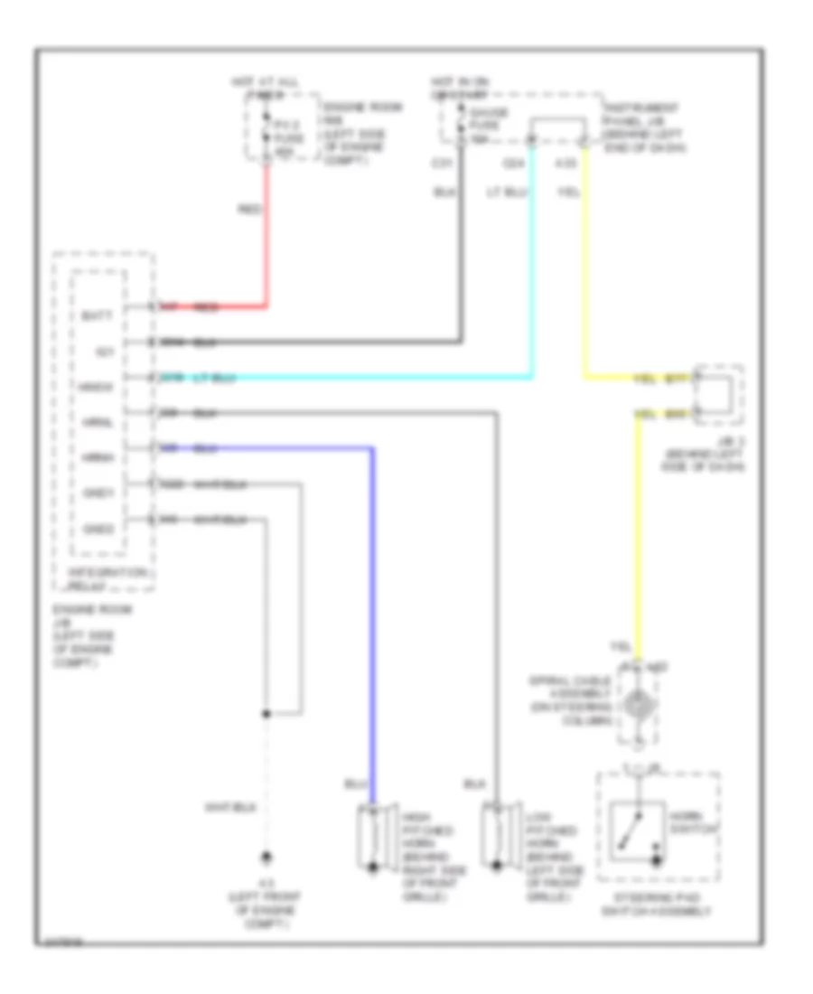
HORN
Horn Wiring Diagram for Toyota Prius Plug-in 2012
List of elements for Horn Wiring Diagram for Toyota Prius Plug-in 2012:
- A3 (left front of engine compt)
- A33
- B65
- B77
- Batt
- C24
- C31
- Engine room j/b (left side of engine compt)
- Engine room r/b (left side of engine compt)
- G14
- G18
- G22
- Gauge fuse 10a
- Gnd1
- Gnd2
- High pitched horn (behind right side of front grille)
- Hnsw
- Horn switch
- Hot at all times
- Hot in on or start
- Hrnh
- Hrnl
- Ig1
- Instrument panel j/b (behind left end of dash)
- Integration relay
- J/b 3 (behind left side of dash)
- L52
- Low pitched horn (behind left side of front grille)
- P/i 2 fuse 40a
- Red
- Spiral cable assembly (on steering column)
- Steering pad switch assembly
INSTRUMENT CLUSTER
Instrument Cluster Wiring Diagram (1 of 3) for Toyota Prius Plug-in 2012
List of elements for Instrument Cluster Wiring Diagram (1 of 3) for Toyota Prius Plug-in 2012:
- (conn a)
- (or red)
- 12v
- A10
- A11
- A12
- A13
- A14
- A15
- A16
- A17
- A18
- A19
- A20
- A21
- A22
- A25
- A26
- A27
- A28
- A29
- A30
- A31
- A32
- A35
- A36
- A37
- A38
- A39
- A40
- A44
- Al1
- Au1
- Au2
- Bkr
- Buzzer
- C18
- Can ic
- Canh
- Canl
- Clkh
- Clkl
- Combination meter assembly
- Computer data lines system
- Cpu
- Da1
- Disp
- Display
- Door locks system
- Driver
- Ecu-b fuse 7.5a
- Efi
- Engine controls system
- Engine oil pressure switch assembly (lower front of engine)
- Engine room r/b (left side of engine compt)
- Es2
- Exterior lights system
- Gauge fuse 10a
- Gnd
- Headlights system
- Hot at all times
- Hot in on or start
- Hour
- I/f
- Ig+
- Ig2
- Ign fuse 10a
- Instrument panel j/b (behind left end of dash)
- Interior lights system
- J/b 3
- J/c l129
- L136
- L2 (center of dash)
- L27
- L52
- Lat
- Lh turn ind
- Lvwg
- Malfunction ind
- Met fuse 7.5a
- Micro computer
- Min
- Pblt
- Pnk
- Red
- Rh turn ind
- Rst
- Security ind
- Sih
- Spiral cable sub-assembly (on steering column)
- Steering pad switch
- Strg
- Sw1
- Sw2
- Sw3
- Tco
- Tire
- Touch sensor
- Trip
- Tws3
- W/ touch sensor
- W/o touch sensor
- Warning systems
Instrument Cluster Wiring Diagram (2 of 3) for Toyota Prius Plug-in 2012
List of elements for Instrument Cluster Wiring Diagram (2 of 3) for Toyota Prius Plug-in 2012:
- (behind center of dash) (w/ safety connect system) dcm (telematics transceiver)
- (behind right end of dash) headlight leveling ecu
- (behind right side of dash) j/b 4
- (rear of cylinder head) (for exhaust heat recirculation system) efi engine coolant temperature sensor
- (top of fuel tank) fuel sender gauge assembly
- (under driver's seat) (w/ separate type amplifier) stereo component amplifier
- 12v
- A21
- A32
- A56
- A67
- A69
- A80
- Al2
- Al7
- Bkr
- Clkh
- Clkl
- Combination meter assembly
- Combination meter mirror
- Da1
- Down
- Gd1
- Gnd
- Hdd
- Hdu
- Hour
- Hud/mode
- Hudd
- Hudi
- Hudo
- Hudu
- Iind
- Ill+
- Ill-
- Ind hud
- Ind navi
- Interior lights system
- J/b 3 (behind left side of dash)
- J/c l93 (behind right end of dash)
- Km mile
- L1 (right side of dash)
- L136
- L137
- L143
- Lat
- Lr1
- Min
- Navi
- Nvi
- Nvm
- Nvsw
- Pnk
- Red
- Rst
- Set
- Sih
- Sil
- Spd
- Spdp
- Spdr
- Stp1
- Stp2
- Stp3
- Stp4
- Tail
- Trip switch
- W/ safety connect
- W/o safety connect
Instrument Cluster Wiring Diagram (3 of 3) for Toyota Prius Plug-in 2012
List of elements for Instrument Cluster Wiring Diagram (3 of 3) for Toyota Prius Plug-in 2012:
- (behind right end of dash)
- (behind right side of dash) power management control ecu
- (behind right side of dash) tire pressure warning ecu
- (right side of dash) l1
- A1 (right front of engine compt)
- A10
- A26
- A64
- A65
- A66
- A72
- Al2
- B20
- B24
- B85
- Brake fluid level warning switch (brake master cylinder reservoir assembly) (on brake master cylinder reservoir assembly)
- C20
- Canh
- Canl
- Computer data lines system
- D35
- D36
- Ecu ig 1 fuse 10a
- Flcy
- Frcy
- Gnd 2
- Hot w/ ig1 1 relay energized
- Instrument panel j/b (behind left end of dash)
- J/b 3 (behind left side of dash)
- J/c l89 (behind center of dash)
- L130
- L149
- L93
- Lbl
- Left front door courtesy light switch assembly (left "b" pillar)
- Left rear door courtesy light switch assembly (left "c" pillar)
- Lr1
- Lrcy
- Ls1
- Main body ecu
- Parking brake switch assembly
- Pkb
- Pnk
- Radio & display receiver assembly & navigation receiver assembly
- Radio & display receiver assembly & radio receiver assembly
- Red
- Right front door courtesy light switch assembly (right "b" pillar)
- Right rear door courtesy light switch assembly (right "c" pillar)
- Skid control ecu w/ actuator assembly (behind left side of dash)
- Sp1
- Spd
- Spdi
- Swg
- Vehicle approaching speaker controller (right end of dash)
- W/ built-in type amplifier
- W/ navigation receiver assembly type
- W/ radio & display receiver assembly type
- W/ separate type amplifier
INTERIOR LIGHTS
Courtesy Lamps Wiring Diagram for Toyota Prius Plug-in 2012
List of elements for Courtesy Lamps Wiring Diagram for Toyota Prius Plug-in 2012:
- (right side of dash) l1
- +b1
- A10
- A49
- A52
- A64
- A65
- A66
- A67
- A72
- Acc
- Altb
- B13
- B17
- B18
- B19
- B20
- B21
- B22
- B23
- B24
- B31
- B47
- B48
- B78
- B83
- Back door lock assembly (center rear of luggage compt)
- Bcty
- Becu
- C18
- C40
- Canh
- Canl
- Computer data lines system
- Courtesy
- Cty
- D21
- D35
- D36
- Dcty
- Diode (back door courtesy light)
- Diode (left front courtesy light)
- Diode (right front courtesy light)
- Dome fuse 10a
- Door
- Door 1 fuse 25a
- Ecu-acc fuse 10a
- Ecu-b fuse 7.5a
- Ecu-ig 1 fuse 10a
- Engine room r/b (left side of engine compt)
- Flcy
- Frcy
- Fspt
- Gnd1
- Gnd2
- Hot at all times
- Hot w/ acc relay energized
- Hot w/ ig 1 relay energized
- Ile
- Instrument panel j/b (behind left end of dash)
- J/b 3 (behind left side of dash)
- J/c l92 (behind left end of dash)
- J/c l93 (behind right end of dash)
- J/c r28 & r29 (left "c" pillar)
- J/c r31 (left "c" pillar)
- L1 (right side of dash)
- L3 (left end of dash)
- Left front door courtesy light assembly
- Left front door courtesy light switch assembly (left "b" pillar)
- Left front map light switch
- Left interior illumination light assembly 1 (if equipped)
- Left rear door courtesy light switch assembly (left "c" pillar)
- Left vanity light assembly
- Left visor assembly
- Lr1
- Lrcy
- Ls1
- Main body ecu
- Map light assembly
- Nl1
- Off
- Ol1
- R1 (left "c" pillar)
- R28
- R29
- Red
- Right front door courtesy light assembly
- Right front door courtesy light switch assembly (right "b" pillar)
- Right front map light switch
- Right interior illumination light assembly 1 (if equipped)
- Right rear door courtesy light switch assembly (right "c" pillar)
- Right vanity light assembly
- Right visor assembly
- Room light assembly 1
- Room light assembly 2
- Ul1
- W/ sliding roof
- W/o sliding roof
Instrument Illumination Wiring Diagram (1 of 3) for Toyota Prius Plug-in 2012
List of elements for Instrument Illumination Wiring Diagram (1 of 3) for Toyota Prius Plug-in 2012:
- (w/o radio & display receiver assembly type & sdars usa)
- A33
- A35
- A37
- A64
- A65
- A67
- A68
- Acc
- Altb
- Auto
- B17
- B18
- B20
- B21
- B43
- Becu
- C18
- C40
- Canh
- Canl
- Computer data lines system
- Dc/dc fuse 125a
- Dcm (telematics transceiver) (w/ safety connect system) (behind center of dash)
- Dim
- Door 1 fuse 25a
- Ecu ig 1 fuse 10a
- Ecu-acc fuse 10a
- Engine room j/b (left side of engine compt)
- Gnd
- Gnd1
- Head
- Headlight cleaner switch assembly
- Headlight dimmer switch assembly
- Hot at all times
- Hot w/ acc relay energized
- Hot w/ ig1 1 relay energized
- Ill+
- Ill-
- Im1
- Instrument panel j/b (behind left end of dash)
- J/b 3 (behind left side of dash)
- J/c l85 (behind center of dash)
- J/c l89 (behind center of dash)
- J/c l92 (behind left end of dash)
- J/c l93 (behind right end of dash)
- L1 (right side of dash)
- L2 (center of dash)
- L3 (left end of dash)
- Left interior illumination light assembly 1 (if equipped)
- Li2
- Light control switch
- Main body ecu
- Map light assembly
- Off
- Panel fuse 10a
- Passenger seat belt warning light assembly
- Red
- Right interior illumination light assembly 1 (if equipped)
- Seat heater switch
- Tail
- Tail relay
- Trly
- Ul1
- Ventilator switch
- W/ sliding roof
- W/o sliding roof
Instrument Illumination Wiring Diagram (2 of 3) for Toyota Prius Plug-in 2012
List of elements for Instrument Illumination Wiring Diagram (2 of 3) for Toyota Prius Plug-in 2012:
- A15
- A19
- A23
- A27
- A28
- A43
- A47
- A71
- A83
- B10
- B22
- B27
- B34
- B35
- B39
- B51
- B62
- B75
- B87
- Dome fuse 10a
- Ecu-b fuse 7.5a
- Engine room r/b (left side of engine compt)
- Gnd
- Hot at all times
- Ill+
- Ill-
- J/b 3 (behind left side of dash)
- J/b 4 (behind right side of dash)
- J/c l129
- L127
- L128
- L130
- L138
- L146
- L147
- L149
- L2 (center of dash)
- Mirror switch assembly ill-
- Navigation receiver assembly (w/ navigation receiver assembly type) radio & display receiver assembly (w/ radio & display receiver assembly type) radio receiver assembly (w/ radio receiver assembly type)
- Outer ill+
- Pnk
- Red
- Swg
- W/ navigation receiver assembly type
- W/ radio & display receiver assembly type & extension module
- W/ radio & display receiver assembly type & w/o sdars usa
- W/ radio receiver assembly type & radio & display receiver assembly type
- W/ radio receiver assembly type & radio & display receiver assembly type w/o extension module
- W/o radio & display receiver assembly type & sdars usa
Instrument Illumination Wiring Diagram (3 of 3) for Toyota Prius Plug-in 2012
List of elements for Instrument Illumination Wiring Diagram (3 of 3) for Toyota Prius Plug-in 2012:
- A/c control assembly
- A18
- A29
- A30
- A31
- Assembly
- B30
- B53
- B90
- Canh
- Canl
- Certification ecu (behind right side of dash)
- Combination meter assembly
- Computer data lines system
- Cpu
- Gauge fuse 10a
- Glove box light (interior illumination light assembly 1)
- Gnd
- Hot w/ ig1 1 relay energized
- I/f
- Ig+
- Ill+
- Ill-
- Instrument panel j/b (behind left end of dash)
- Integration control & panel assembly
- J/b 3 (behind left side of dash)
- J/c l129
- L1 (right side of dash)
- L2 (center of dash)
- L27
- L52
- L62
- Light control rheostat
- Lb1
- Pad
- Pnk
- Power switch
- Red
- Spiral cable assembly (on steering column)
- Steering
- Sw1
- Sw2
- Sw3
- Swil
- Switch
- Tail cancel switch
- Transmission shift main switch
- Trip switch (w/ safety connect)
- W/ radio & display receiver assembly type & w/o sdars usa
- W/o radio & display receiver assembly type & sdars usa
NAVIGATION
Lane Departure Warning Wiring Diagram (1 of 2) for Toyota Prius Plug-in 2012
List of elements for Lane Departure Warning Wiring Diagram (1 of 2) for Toyota Prius Plug-in 2012:
- A61
- A67
- A68
- A71
- B49
- B60
- B76
- B78
- Ca1n
- Ca1p
- Ca2h
- Ca2l
- Cchg
- Ccs
- Computer data lines system
- Cruise control system
- Driving support ecu (behind right side of dash)
- Front washer switch
- Front wiper switch
- Fuse block (behind left kick panel)
- Gnd
- Headlight dimmer switch assembly
- Hitp
- Int
- J/b 3 (behind left side of dash)
- J/b 4 (behind right side of dash)
- J/c l86 (behind right end of dash)
- J/c l87 (behind right end of dash)
- J/c l92 (behind left end of dash)
- J/c l93 (behind right end of dash)
- L1 (right side of dash)
- L3 (center of dash)
- L48
- L49
- Left
- Mist
- Off
- Pbsw
- Pnk
- Red
- Right
- Spsw
- St1-
- Stp-
- Turn switch
- Wash
- Windshield wiper switch assembly
- Wip 3 fuse 10a
- Wip 4 fuse 10a
- Wip2
- Wnkl
- Wnkr
Lane Departure Warning Wiring Diagram (2 of 2) for Toyota Prius Plug-in 2012
List of elements for Lane Departure Warning Wiring Diagram (2 of 2) for Toyota Prius Plug-in 2012:
- +res
- -set
- A11
- A12
- A24
- A31
- A37
- A42
- A54
- A60
- A67
- Al4
- B16
- B52
- B57
- B58
- B59
- B64
- B68
- B69
- B70
- B73
- B74
- B76
- B79
- B83
- B84
- B88
- Buzzer
- C18
- Ca1n
- Ca1p
- Can ic
- Cancel
- Canh
- Canl
- Combination meter
- Computer data lines system
- Cpu
- Cruise control main switch
- Data lines system
- Display
- Distance control
- Driver
- Ecu-b fuse 7.5a
- Ecu-ig 2 fuse 10a
- Engine room r/b (left side of engine compt)
- Gauge fuse 10a
- Gnd
- Hitp
- Hot at all times
- Hot in on or start
- I/f
- Ig+
- Igb
- Instrument panel j/b (behind left end of dash)
- J/b 3 (behind left side of dash)
- J/b 4 (behind right side of dash)
- J/c l129
- J/c l93 (behind right end of dash)
- L1 (right side of dash)
- L2 (center of dash)
- L27
- L52
- Lane recognition camera sensor (center front of roof)
- Lka
- Millimeter wave radar sensor (behind center of front grille)
- Mode
- On-off
- Pnk
- Red
- Sgnd
- Spiral cable sub- assembly
- Steering pad switch assembly
- Ul2
- Wip fuse 30a
- Z10
Navigation Wiring Diagram, with Built-in Amplifier (1 of 3) for Toyota Prius Plug-in 2012
List of elements for Navigation Wiring Diagram, with Built-in Amplifier (1 of 3) for Toyota Prius Plug-in 2012:
- (if equipped) rear television camera assembly
- A14
- A16
- A24
- A31
- A32
- A37
- A50
- A65
- A72
- Acc 1
- Adpg
- Agnd
- Al1
- Al2
- Al4
- Atx+
- B1+
- B16
- B72
- B76
- B79
- B84
- B88
- B91
- C18
- C20
- C31
- Ca+
- Can h
- Can l
- Cb+
- Cgnd
- Computer data lines system
- Cv+
- Cv-
- Ecu-acc fuse 10a
- Ecu-b fuse 7.5a
- Ecu-ig2 fuse 10a
- Engine room r/b (left side of engine compt)
- Gauge fuse 10a
- Hot at all times
- Hot in on or acc
- Hot in on or start
- Ign fuse 10a
- Instrument panel j/b (behind left end of dash)
- J/b 3 (behind left side of dash)
- J/b 4 (behind right side of dash)
- J/c
- J/c l85 (behind center of dash)
- J/c l89 (behind center of dash)
- L129
- L148
- L149
- L150
- Ll2
- Lr1
- Macc
- Main antenna
- Mco+
- Mco-
- Microphone & microphone amplifier
- Min+
- Min-
- Nca
- P/i 2 fuse 40a
- Parking brake switch assembly
- Pkb
- Pnk
- Rad 1 fuse 15a
- Radio & display receiver assembly
- Receiver assembly w/o sdars usa
- Red
- Rev
- Sgnd
- Skid control ecu w/ actuator assembly (behind left side of dash)
- Sns 2
- Sns2
- Spd
- Stereo jack adapter assembly 1
- Sub antenna
- Sw1
- Sw2
- Swg
- Ul2
- Va-
- Val+
- Var+
- Vr1
- W/ extension module
- W/ radio & display
- W/o extension module
Navigation Wiring Diagram, with Built-in Amplifier (2 of 3) for Toyota Prius Plug-in 2012
List of elements for Navigation Wiring Diagram, with Built-in Amplifier (2 of 3) for Toyota Prius Plug-in 2012:
- (behind center of dash)
- (behind center of dash) shift lever position sensor
- (behind right side of dash) power management control ecu
- (left side of engine compt) engine room j/b
- A21
- A3 (left front of engine compt)
- Au1
- Au2
- Avc+
- Avc-
- Bat
- Bkup
- Ca1h
- Ca1l
- Combination meter
- Computer data lines system
- Cpu
- E2x1
- E2x2
- Eau
- G13
- G14
- G22
- Gnd1
- Gnd2
- Hall ic
- I/f
- Ig+
- Ig1
- Integration relay
- L2 (center of dash)
- L27
- L52
- Lz1
- Micro computer
- Mode
- Mute
- Nav
- Nca
- Off hook
- On hook
- Pnk
- Radio & display receiver assembly
- Red
- Seek+
- Seek-
- Shd3
- Shift lever position sensor 2
- Spiral cable sub-assembly (on steering column)
- Steering pad switch assembly
- Tan
- Touch sensor
- Vcx1
- Vcx2
- Vcx3
- Vcx4
- Voice
- Volume+
- Volume-
- Vsx1
- Vsx2
- Vsx3
- Vsx4
- W/ touch sensor
- Z22
Navigation Wiring Diagram, with Built-in Amplifier (3 of 3) for Toyota Prius Plug-in 2012
List of elements for Navigation Wiring Diagram, with Built-in Amplifier (3 of 3) for Toyota Prius Plug-in 2012:
- (if equipped) extension module
- (if equipped) sdars antenna
- Acc
- Agnd
- Avc+
- Avc-
- Fl+
- Fl-
- Fr+
- Fr-
- Gnd
- Gnd1
- Gps antenna
- Hsyn
- L146
- L147
- L151
- L2 (center of dash)
- Left front speaker assembly 1
- Left front speaker assembly 2
- Left rear speaker assembly
- Li1
- Li2
- Lr2
- Ls2
- Mic+
- Mic-
- Mute
- Nca
- Nl2
- Ol2
- Pnk
- Ps1
- Qr1
- Radio & display receiver assembly
- Red
- Right front speaker assembly 1
- Right front speaker assembly 2
- Right rear speaker assembly
- Rl+
- Rl-
- Rr+
- Rr-
- Shd1
- Shd2
- Shd3
- Spd
- Tan
- V-b
- V-g
- V-r
- Vbus
- Vol+
- Vol-
- Vshd
- Vsyn
- Z21
- Z23
Navigation Wiring Diagram, with Radio & Display Amplifier & Separate Amplifier (1 of 5) for Toyota Prius Plug-in 2012
List of elements for Navigation Wiring Diagram, with Radio & Display Amplifier & Separate Amplifier (1 of 5) for Toyota Prius Plug-in 2012:
- (left side of liftgate) rear television camera
- A14
- A16
- A24
- A31
- A32
- A37
- A50
- A62
- A65
- A72
- Adpg
- Agnd
- Al1
- Al4
- Au1
- Au2
- B16
- B72
- B76
- B79
- B84
- B88
- B91
- C18
- C20
- C31
- Ca+
- Canh
- Canl
- Cb+
- Cgnd
- Computer data lines system
- Cv+
- Cv-
- Eau
- Ecu-acc fuse 10a
- Ecu-b fuse 7.5a
- Ecu-ig 2 fuse 10a
- Engine room r/b (left side of engine compt)
- Fuse p/i 2 40a
- Gauge fuse 10a
- Gps antenna
- Hot at all times
- Hot in on or acc
- Hot in on or start
- Ign fuse 10a
- Instrument panel j/b (behind left end of dash)
- J/b 3 (behind left side of dash)
- J/b 4 (behind right side of dash)
- J/c l129
- J/c l85 (behind center of dash)
- L148
- L149
- L52
- Ll2
- Lr1
- Macc
- Main antenna
- Micro computer
- Min+
- Min-
- Mode
- Mut2
- Nca
- Off hook
- On hook
- Parking brake switch
- Pkb
- Pnk
- Rad 1 fuse 15a
- Radio & display receiver assembly
- Red
- Rev
- Seek+
- Seek-
- Sgnd
- Sns2
- Spd
- Spiral cable sub-assembly (on steering column)
- Steering pad switch assembly
- Stereo jack adapter assembly 1
- Sw1
- Sw2
- Swg
- Touch sensor
- Va-
- Val+
- Var+
- Voice
- Volume+
- Volume-
- Vr1
- W/o safety connect
Navigation Wiring Diagram, with Radio & Display Amplifier & Separate Amplifier (2 of 5) for Toyota Prius Plug-in 2012
List of elements for Navigation Wiring Diagram, with Radio & Display Amplifier & Separate Amplifier (2 of 5) for Toyota Prius Plug-in 2012:
- (behind center of dash) shift lever position sensor
- (behind center of dash) shift lever position sensor 2
- (behind right side of dash) power management control ecu
- (left side of engine compt) engine room j/b
- A21
- A3 (left front of engine compt)
- Acc1
- Bat
- Bkup
- Ca1h
- Ca1l
- Computer data lines system
- E2x1
- E2x2
- G13
- G14
- G22
- Gnd1
- Gnd2
- Hall ic
- Ig1
- Integration relay
- Ivo+
- Ivo-
- L138
- L2 (center of dash)
- Lz1
- Macc
- Map light assembly
- Mco+
- Mco-
- Microphone & microphone amplifier
- Mut1
- Nav
- Nca
- Pnk
- Radio & display receiver assembly
- Red
- Sdars antenna
- Sns2
- Sub antenna
- Tx2+
- Tx2-
- Ul2
- Vcx1
- Vcx2
- Vcx3
- Vcx4
- Vsx1
- Vsx2
- Vsx3
- Vsx4
- W/ safety connect
- W/ sliding roof
- W/o safety connect
- W/o sliding roof
Navigation Wiring Diagram, with Radio & Display Amplifier & Separate Amplifier (3 of 5) for Toyota Prius Plug-in 2012
List of elements for Navigation Wiring Diagram, with Radio & Display Amplifier & Separate Amplifier (3 of 5) for Toyota Prius Plug-in 2012:
- (if equipped) extension module
- Acc
- Agnd
- Avc+
- Avc-
- Gnd
- Gps antenna
- Hsyn
- L151
- Mic+
- Mic-
- Mute
- Nca
- Pnk
- Radio & display receiver assembly
- Red
- Shd1
- Shd2
- Shd3
- Spd
- V-b
- V-g
- V-r
- Vbus
- Vol+
- Vol-
- Vshd
- Vsyn
- Z21
- Z22
- Z23
Navigation Wiring Diagram, with Radio & Display Amplifier & Separate Amplifier (4 of 5) for Toyota Prius Plug-in 2012
List of elements for Navigation Wiring Diagram, with Radio & Display Amplifier & Separate Amplifier (4 of 5) for Toyota Prius Plug-in 2012:
- (behind left side of dash) (w/ actuator assembly) skid control ecu
- A69
- Al2
- B85
- Ca1h
- Ca1l
- Can ic
- Combination meter
- Computer data lines system
- Cpu
- Dcm (telematics transceiver) (behind center of dash)
- I/f
- Ig+
- J/b 3 (behind left side of dash) a26
- J/b 4 (behind right side a21
- J/c l89 (behind center of dash)
- L2 (center of dash)
- L27
- Left rear speaker assembly
- Li1
- Li2
- Lr2
- Ls2
- Mci+
- Mci-
- Mco+
- Mco-
- Mcvd
- Mute
- Nca
- Of dash)
- Pnk
- Ps1
- Qr1
- Red
- Right rear speaker assembly
- Sgnd
- Sp1
- Spi+
- Spi-
- Spo+
- Spo-
- Ul1
- Ul2
- W/ safety connect
Navigation Wiring Diagram, with Radio & Display Amplifier & Separate Amplifier (5 of 5) for Toyota Prius Plug-in 2012
List of elements for Navigation Wiring Diagram, with Radio & Display Amplifier & Separate Amplifier (5 of 5) for Toyota Prius Plug-in 2012:
- (behind right side of dash) j/b 4
- A67
- Acc
- Al4
- Amp fuse 2 30a
- Amp fuse 30a
- B2+
- B53
- Engine room r/b (left side of engine compt)
- Fl+
- Fl-
- Fr+
- Fr-
- Gnd
- Hot at all times
- J/c l85 (behind center of dash)
- L142
- L143
- L2 (center of dash)
- Left front speaker assembly 1
- Left instrument panel speaker (instrument panel speaker panel sub-assembly 2)
- Left rear speaker assembly 2
- Li1
- Li2
- Ll1+
- Ll1-
- Lr1
- Ls2
- Mute
- Nca
- Nl2
- Ol2
- Pnk
- Ps1
- Qr1
- Red
- Right front speaker assembly 1
- Right instrument panel speaker (instrument panel speaker panel sub-assembly 1)
- Right rear speaker assembly 2
- Rl+
- Rl-
- Rr+
- Rr-
- Sld
- Sld1 & gnd2
- Spd
- Stereo component amplifier (under driver's seat)
- Tmut
- Twl+
- Twl-
- Twr+
- Twr-
- Tx+
- Tx-
- W/ safety connect
- W/o safety connect
- Wfl+
- Wfl-
- Wfr+
- Wfr-
Navigation Wiring Diagram, without Radio & Display Amplifier with Separate Amplifier (1 of 4) for Toyota Prius Plug-in 2012
List of elements for Navigation Wiring Diagram, without Radio & Display Amplifier with Separate Amplifier (1 of 4) for Toyota Prius Plug-in 2012:
- A14
- A24
- A31
- A32
- A37
- A50
- A62
- A65
- A72
- Acc1
- Adpg
- Agnd
- Al1
- Al4
- Au1
- Au2
- B1+
- B16
- B72
- B76
- B79
- B84
- B88
- B91
- C18
- C31
- Canh
- Canl
- Computer data lines system
- Eau
- Ecu-acc fuse 10a
- Ecu-b fuse 7.5a
- Ecu-ig 2 fuse 10a
- Engine room r/b (left side of engine compt)
- Fl+
- Fl-
- Fr+
- Fr-
- Fuse p/i 2 40a
- Gauge fuse 10a
- Gnd
- Gps antenna
- Hot at all times
- Hot in on or acc
- Hot in on or start
- Ign fuse 10a
- Instrument panel j/b (behind left end of dash)
- J/b 3 (behind left side of dash)
- J/b 4 (behind right side of dash)
- J/c l129
- J/c l85 (behind center of dash)
- L127
- L130
- L131
- L2 (center of dash)
- L52
- Ll2
- Macc
- Main antenna
- Micro computer
- Min+
- Min-
- Mode
- Mut2
- Navigation receiver assembly
- Nca
- Off hook
- On hook
- Pnk
- Rad 1 fuse 15a
- Red
- Rev
- Seek+
- Seek-
- Sgnd
- Sns2
- Spd
- Spiral cable sub-assembly (on steering column)
- Steering pad switch assembly
- Stereo jack adapter assembly 1
- Sw1
- Sw2
- Swg
- Touch sensor
- Tx1+
- Tx1-
- Va-
- Val+
- Var+
- Voice
- Volume+
- Volume-
- W/o safety connect
Navigation Wiring Diagram, without Radio & Display Amplifier with Separate Amplifier (2 of 4) for Toyota Prius Plug-in 2012
List of elements for Navigation Wiring Diagram, without Radio & Display Amplifier with Separate Amplifier (2 of 4) for Toyota Prius Plug-in 2012:
- (behind center of dash) shift lever position sensor
- (behind right side of dash) power management control ecu
- (left side of engine compt) engine room j/b
- A21
- A3 (left front of engine compt)
- Bat
- Bkup
- Brk sw
- Ca1h
- Ca1l
- Cb+
- Cgnd
- Computer data lines system
- Cv+
- Cv-
- E2x1
- E2x2
- G13
- G14
- G22
- Gnd1
- Gnd2
- Hall ic
- Ig1
- Integration relay
- L111
- L128
- Lr1
- Lz1
- Macc
- Map light assembly
- Mco+
- Mco-
- Microphone & microphone amplifier
- Nav
- Navigation receiver assembly
- Nca
- Pnk
- Rear television camera (left side of liftgate)
- Red
- Rl+
- Rl-
- Sdars antenna
- Sns2
- Sub antenna
- Ul2
- Vcx1
- Vcx2
- Vcx3
- Vcx4
- Vr1
- Vsx1
- Vsx2
- Vsx3
- Vsx4
- W/ safety connect
- W/ sliding roof
- W/o safety connect
- W/o sliding roof
Navigation Wiring Diagram, without Radio & Display Amplifier with Separate Amplifier (3 of 4) for Toyota Prius Plug-in 2012
List of elements for Navigation Wiring Diagram, without Radio & Display Amplifier with Separate Amplifier (3 of 4) for Toyota Prius Plug-in 2012:
- (behind center of dash) shift lever position sensor 2
- (behind left side of dash) (w/ actuator assembly) skid control ecu
- A16
- A21
- A26
- A69
- Al2
- B85
- C20
- Ca1h
- Ca1l
- Can ic
- Combination meter
- Computer data lines system
- Cpu
- Dcm (telematics transceiver) (behind center of dash)
- Hall ic
- I/f
- Ig+
- Instrument panel j/b (behind left end of dash)
- J/b 3 (behind left side of dash)
- J/b 4 (behind right side of dash)
- J/c l89 (behind center of dash)
- L2 (center of dash)
- L27
- Left rear speaker assembly
- Li1
- Li2
- Lr2
- Ls2
- Mci+
- Mci-
- Mco+
- Mco-
- Mcvd
- Mute
- Nca
- Parking brake switch
- Pnk
- Ps1
- Qr1
- Red
- Right rear speaker assembly
- Sgnd
- Sp1
- Spi+
- Spi-
- Spo+
- Spo-
- Ul1
- Ul2
- W/ safety connect
Navigation Wiring Diagram, without Radio & Display Amplifier with Separate Amplifier (4 of 4) for Toyota Prius Plug-in 2012
List of elements for Navigation Wiring Diagram, without Radio & Display Amplifier with Separate Amplifier (4 of 4) for Toyota Prius Plug-in 2012:
- (behind right side of dash) j/b 4
- A67
- Acc
- Al4
- Amp fuse 2 30a
- Amp fuse 30a
- B2+
- B53
- Engine room r/b (left side of engine compt)
- Fl+
- Fl-
- Fr+
- Fr-
- Gnd
- Hot at all times
- J/c l85 (behind center of dash)
- L142
- L143
- L2 (center of dash)
- Left front speaker assembly 1
- Left instrument panel speaker (instrument panel speaker panel sub-assembly 2)
- Left rear speaker assembly 2
- Li1
- Li2
- Ll1+
- Ll1-
- Lr1
- Ls2
- Mute
- Nca
- Nl2
- Ol2
- Pnk
- Ps1
- Qr1
- Red
- Right front speaker assembly 1
- Right instrument panel speaker (instrument panel speaker panel sub-assembly 1)
- Right rear speaker assembly 2
- Rl+
- Rl-
- Rr+
- Rr-
- Sld
- Sld1 & gnd
- Spd
- Stereo component amplifier (under driver's seat)
- Tmut
- Twl+
- Twl-
- Twr+
- Twr-
- Tx+
- Tx-
- W/ safety connect
- W/o safety connect
- Wfl+
- Wfl-
- Wfr+
- Wfr-
Telematics Wiring Diagram for Toyota Prius Plug-in 2012
List of elements for Telematics Wiring Diagram for Toyota Prius Plug-in 2012:
- (behind right side of dash) j/b 4
- A14
- A21
- A23
- A26
- A31
- A37
- A50
- A67
- A75
- A80
- Acc
- Al2
- B17
- B53
- B79
- B85
- B91
- Backup battery (mayday battery) (behind center of dash)
- Bbi+
- Bbi-
- Bbo+
- Bbo-
- Btr1
- Btr2
- C18
- Canh
- Canl
- Combination meter
- Computer data lines system
- Cpu
- Ctr1
- Ctr2
- Dcm (telematics transceiver) (behind center of dash)
- Ecu-acc fuse 10a
- Ecu-b fuse 7.5a
- Engine room r/b (left side of engine compt)
- Fr+
- Fr-
- Gauge fuse 10a
- Gnd
- Gnd1
- Gps antenna
- Gsw
- Hot at all times
- Hot in on or acc
- Hot in on or start
- I/f
- Ig2
- Ign fuse 10a
- Ill+
- Ind1
- Ind2
- Instrument panel j/b (behind left end of dash)
- Instrument panel speaker panel sub-assembly 1
- Interior lights system
- J/b 3 (behind left side of dash)
- J/b 4 (behind right side of dash)
- J/c l129
- J/c l85 (behind center of dash)
- J/c l87 (behind right end of dash)
- J/c l89 (behind center of dash)
- J/c l93 (behind right end of dash)
- L1 (right side of dash)
- L130
- L142
- L143
- L149
- L2 (center of dash)
- L27
- Li1
- Li2
- Macc
- Map light assembly
- Mayday fuse 10a
- Mci+
- Mci-
- Mco+
- Mco-
- Mcvd
- Microphone & microphone amplifier
- Min+
- Min-
- Mute
- Navigation receiver assembly (w/ navigation) radio & display receiver assembly (w/o navigation)
- Nca
- Pnk
- Red
- Sgnd
- Sig-
- Sig1
- Sil
- Skid control ecu (behind left side of dash)
- Sled
- Sns2
- Sos
- Sp1
- Spdp
- Spi+
- Spi-
- Spo+
- Spo-
- Stereo component amplifier (under driver's seat)
- Telephone antenna
- Tmut
- Ul1
- Ul2
- W/ navigation
- W/ sliding roof
- W/o navigation
- W/o sliding roof
Vehicle Proximity Notification Wiring Diagram for Toyota Prius Plug-in 2012
List of elements for Vehicle Proximity Notification Wiring Diagram for Toyota Prius Plug-in 2012:
- (behind left side of dash) j/c l92
- (of dash behind center) j/c l89
- A1 (right front of engine compt)
- A28
- A3 (left front of engine compt)
- A31
- A40
- A50
- A51
- A53
- A58
- A67
- A76
- Al1
- Al2
- Al4
- B29
- C11
- C12
- Combination meter
- Cpu
- Da1
- Ecu-ig 1 fuse 10a
- Engine oil pressure switch assembly (lower front of engine)
- Engine room r/b (left side of engine compt)
- Gauge fuse 10a
- Gnd
- Hot at all times
- Hot in on or start
- I/f
- Ig+
- Instrument panel j/b (behind left end of dash)
- J/c 3 (behind left side of dash)
- J/c a50 & a51 (behind right end of dash)
- J/c a52 & a53 (behind left a52 end of dash)
- J/c l129
- L2 (center of dash)
- L3 (left end of dash)
- Lb1
- Opsw
- Out
- P con main fuse 7.5a
- Red
- Sftp
- Skid control ecu w/ actuator assembly
- Sp+
- Sp-
- Spd
- Stop fuse 10a
- Stop light ecu control assembly (behind left side of dash)
- Stop light switch assembly (above brake pedal on bracket)
- Stp
- Transmission shift main switch
- Vehicle approaching speaker assembly (right end of dash)
- Vehicle approaching speaker controller (right end of dash)
POWER DISTRIBUTION
Power Distribution Wiring Diagram (1 of 3) for Toyota Prius Plug-in 2012
List of elements for Power Distribution Wiring Diagram (1 of 3) for Toyota Prius Plug-in 2012:
- (behind left end of dash) instrument panel j/b
- (left side of engine compt) engine room r/b
- A/c fuse 10a
- A22
- A30
- A31
- A37
- A4 (left front of engine compt)
- A40
- A53
- Abs mtr 1 fuse 30a
- Abs mtr 2 fuse 30a
- Air conditioning & cooling fans systems
- Air conditioning system
- Anti-lock brakes & wiper/washer systems
- Anti-lock brakes system
- B16
- B25
- Batt
- Batt fan fuse 10a
- Batt fan relay
- Battery
- Becu
- C18
- C26
- C28
- C30
- C31
- D/l source relay
- Dc/dc fuse 125a
- Dcdc
- Defogger & air conditioning systems
- Dome fuse 10a
- Ecu- ig 1 fuse 10a
- Ecu-b fuse 7.5a
- Ecu-ig 2 fuse 10a
- Efi main fuse 20a
- Efi main relay
- Electronic power steering system
- Engine controls & cruise control systems
- Engine controls system
- Engine room j/b (left side of engine compt)
- Eps fuse 60a
- Etcs fuse 10a
- Exterior lights system
- From ig1 2 relay (diagram 2 of 3)
- From turn & c haz fuse in engine room r/b (diagram 1 of 3)
- Fusible link block (right rear of vehicle)
- G14
- Gauge fuse 10a
- Headlights system
- Ig1
- Ig1 1 relay
- Ig1d
- Ig2
- Ig2 fuse 20a
- Ig2 relay
- Ig2d
- Instrument cluster system
- Instrument panel j/b (behind left end of dash)
- Integration relay
- J/c l92 (behind left end of dash)
- J/c l93 (behind right end of dash)
- L1 (right side of dash)
- L3 (center of dash)
- Main body ecu
- Main fuse 140a
- Mirrors & interior lights systems
- Navigation & sound systems
- Navigation system
- P-con mtr fuse 30a
- P/i 1 fuse 60a
- P/i 2 fuse 40a
- Power management control ecu (behind right side of dash)
- Rad 1 fuse 15a
- Red
- Shift interlock & transmissions systems
- Short pin
- To amp fuse (diagram 2 of 3)
- To dc/dc fuse in engine room j/b (diagram 1 of 3)
- To htr fuse in engine room r/b (diagram 2 of 3)
- To ig1 3 relay (diagram 2 of 3)
- To instrument panel j/b (diagram 3 of 3)
- Turn & haz fuse 10a
- Warning systems
Power Distribution Wiring Diagram (2 of 3) for Toyota Prius Plug-in 2012
List of elements for Power Distribution Wiring Diagram (2 of 3) for Toyota Prius Plug-in 2012:
- A11
- A21
- Abs main 1 fuse 20a
- Abs main 2 fuse 7.5a
- Air conditioning & defogger systems
- Air conditioning system
- Al2
- Am2 fuse 7.5a
- Am21
- Am22
- Amp fuse 30a
- Amp2 fuse 30a
- Anti-lock brakes system
- B32
- Cds fuse 30a
- Cooling fans & air conditioning systems
- Cruise control & engine controls systems
- D16
- Dc/dc-s fuse 5a
- Door locks & anti-theft systems
- Drl fuse 7.5a
- Ecu-b2 fuse 7.5a
- Ecu-b3 fuse 10a
- Eng w/p fuse 30a
- Engine controls & transmissions systems
- Engine controls system
- Engine room r/b (left side of engine compt)
- From acc relay (diagram 3 of 3)
- From dc/dc fuse in engine room j/b (diagram 1 of 3)
- From ecu-b2 e fuse (diagram 2 of 3)
- From ig1 1 relay (diagram 1 of 3)
- From p/i 2 fuse (diagram 1 of 3)
- Gnd
- H-lp cln fuse 30a
- H-lp hi main fuse 20a
- Headlights system
- Htr fuse 50a
- Ig1 2 relay
- Ig1 3 relay
- Igct fuse 30a
- Instrument panel j/b (behind left end of dash)
- J/b 3 (behind left side of dash)
- L1 (right side of dash)
- Mayday fuse 10a
- Navigation & sound systems
- Navigation system
- P con main fuse 7.5a
- Power management control ecu (behind right side of dash)
- Power switch
- Rdi fuse 30a
- Red
- Rr wip fuse 20a
- Seat htr fl fuse 10a
- Seat htr fr fuse 10a
- Seats system
- Sound & navigation systems
- Ss1
- Ss2
- Ssw1
- Ssw2
- To acc relay (diagram 3 of 3)
- To ecu-b3 fuse (diagram 2 of 3)
- To ig1 1 relay (diagram 1 of 3)
- Transmissions & shift interlock systems
- Washer fuse 15a
- Wip fuse 30a
- Wiper/washer system
Power Distribution Wiring Diagram (3 of 3) for Toyota Prius Plug-in 2012
List of elements for Power Distribution Wiring Diagram (3 of 3) for Toyota Prius Plug-in 2012:
- A10
- A13
- A14
- A23
- A32
- A35
- A43
- A44
- A50
- A54
- Acc
- Acc relay
- Accd
- Altb
- Anti-lock brakes & engine controls systems
- Anti-lock brakes, engine controls, cruise control, shift interlock, controls & exterior lights systems
- Bk/dr relay
- C10
- C11
- C12
- C13
- C14
- Center power outlet socket assembly
- Cig fuse 15a
- Computer data lines system
- D fr door fuse 25a
- D/l source relay
- D13
- D18
- Door 1 fuse 25a
- Door locks & power windows systems
- Door rl fuse 25a
- Door rr fuse 25a
- Ecu-acc fuse 10a
- Engine controls & instrument cluster systems
- Engine controls system
- Exterior lights & anti-lock brakes systems
- Exterior lights & headlights systems
- Fr fog fuse 7.5a
- Fr fog relay
- From engine room j/b (diagram 1 of 3)
- From ig1 3 relay (diagram 2 of 3)
- Ign fuse 10a
- Instrument panel j/b (behind left end of dash)
- Interior lights system
- J/c l93 (behind right end of dash)
- L1 (right side of dash)
- Main body ecu
- Met fuse 7.5a
- Obd fuse 7.5a
- P fr door fuse 25a
- P/point relay
- Panel fuse 10a
- Power management control ecu (behind right side of dash)
- Power outlet socket assembly
- Power tops system
- Power windows system
- Psb fuse 30a
- Pwr outlet fuse 15a
- Pwr seat fl fuse 30a
- Red
- S/roof fuse 30a
- Seats system
- Sound, navigation & mirrors systems
- Stop fuse 10a
- Tail fuse 10a
- Tail relay
- To ig1 3 relay (diagram 2 of 3)
- Trly
POWER DOOR LOCKS
Power Door Locks Wiring Diagram (1 of 5) for Toyota Prius Plug-in 2012
List of elements for Power Door Locks Wiring Diagram (1 of 5) for Toyota Prius Plug-in 2012:
- (right side of dash) l1
- +b1
- +b2
- A21
- A22
- A3 (left front of engine compt)
- A60
- A67
- Al2
- Am2 fuse 7.5a
- Am21
- Am22
- B10
- B31
- B32
- B33
- Can2h
- Can2l
- Computer data lines system
- E2x1
- E2x2
- Ecu-b fuse 7.5a
- Ecu-b2 fuse 7.5a
- Engine room r/b (left side of engine compt)
- Hall ic
- Hot at all times
- Igct 2 fuse 10a
- Igct fuse 30a
- Igct relay
- Imi
- Imo
- Inds
- Indw
- J/b 3 (behind left side of dash)
- J/c a55 (behind right end of dash)
- J/c a56 (behind left end of dash)
- J/c l93 (behind right end of dash)
- L1 (right side of dash)
- Lin2
- Lb1
- Lz1
- Mrel
- Pnk
- Power management control ecu (behind right side of dash)
- Red
- Shift lever position sensor (behind center of dash)
- Shift lever position sensor 2 (behind center of dash)
- Ssw1
- Ssw2
- Stp
- Transmission shift main switch
- Vcx1
- Vcx2
- Vcx3
- Vcx4
- Vsx1
- Vsx2
- Vsx3
- Vsx4
- W/ id code box
- W/o id code box
Power Door Locks Wiring Diagram (2 of 5) for Toyota Prius Plug-in 2012
List of elements for Power Door Locks Wiring Diagram (2 of 5) for Toyota Prius Plug-in 2012:
- (above brake pedal, on bracket) stop light switch
- (behind left end of dash) main body ecu
- A31
- A35
- A37
- A48
- A50
- A59
- A64
- Acc
- Altb
- B25
- B26
- B28
- Becu
- Bk/dr relay
- Buzzer
- C11
- C18
- Can ic
- Canh
- Canl
- Combination meter assembly
- Computer data lines system
- Cpu
- D/l source relay
- Display
- Door fuse 25a
- Driver
- Ecu- acc fuse 10a
- Ecu- ig 1 fuse 10a
- Efii
- Efio
- Gauge fuse 10a
- Gnd
- Gnd1
- Hot at all times
- Hot in on or acc
- Hot in on or start
- I/f
- Id code box (behind left side of dash)
- Ig+
- Instrument panel j/b (behind left end of dash)
- J/b 3 (behind left side of dash)
- J/c a50 & a51 (behind left end of a51 dash)
- J/c l129
- J/c l92 (behind left end of dash)
- J/c l93 (behind right end of dash)
- L1 (right side of dash)
- L2 (center of dash)
- L3 (left end of dash)
- Lin1
- Pnk
- Red
- Security ind
- Stop fuse 10a
- To d/l relay (diagram 3 of 5)
- Tr+
Power Door Locks Wiring Diagram (3 of 5) for Toyota Prius Plug-in 2012
List of elements for Power Door Locks Wiring Diagram (3 of 5) for Toyota Prius Plug-in 2012:
- (behind left end of dash) main body ecu
- A1 (right front of engine compt)
- A38
- A63
- Act+
- Act-
- Actd
- B10
- B29
- Bzr
- C23
- Canh
- Canl
- Computer data lines system
- D dr unlock relay
- D/l relay
- D11
- D12
- D25
- Dr unlock relay
- From bk/dr a
- From d/l source b
- Haz
- Instrument panel j/b (behind left end of dash)
- J/b 3 (behind left side of dash)
- J/c l89 (behind center of dash)
- L1 (right side of dash)
- L3 (left end of dash)
- Left front door lock motor (rear of driver's door)
- Left rear door lock motor (rear of left rear door)
- Lr1
- Lr2
- Ls1
- Lsr
- Nl1
- Ol1
- Pnk
- Ps1
- Qr1
- R1 (left "c" pillar)
- Red
- Relay (diagram 2 of 5)
- Right front door lock motor (rear of front passenger's door)
- Right rear door lock motor (rear of right rear door)
- S1 (right "c" pillar)
- Turn signal flasher (behind left end of dash)
- Ul3
- Wireless door lock buzzer (left rear of engine compt)
Power Door Locks Wiring Diagram (4 of 5) for Toyota Prius Plug-in 2012
List of elements for Power Door Locks Wiring Diagram (4 of 5) for Toyota Prius Plug-in 2012:
- (behind left end of dash) main body ecu
- A10
- A14
- A27
- A66
- A72
- Agnd
- B20
- B24
- B46
- B80
- Back door lock assembly (center rear of luggage compt)
- Bcty
- C20
- Code
- Control circuit
- Courtesy
- D fr door fuse 25a
- D35
- D36
- Door lock switch
- Flcy
- Frcy
- Gnd
- Hot at all times
- Inds
- Indw
- Instrument panel j/b (behind left end of dash)
- J/b 3 (behind left side of dash)
- J/c l89 (behind center of dash)
- J/c r28 & r29 (left "c" pillar) r29
- J/c r31 (left "c" pillar)
- L1 (right side of dash)
- L3 (left end of dash)
- Left front door courtesy light switch (left "b" pillar)
- Left rear door courtesy light switch (left "c" pillar)
- Lin1
- Lin2
- Lock
- Lr1
- Lr2
- Lrcy
- Ls1
- Lsfl
- Lsfr
- Multiplex network master switch assembly
- Nl1
- Ol1
- Ol2
- Parking brake switch
- Pkb
- Pnk
- Power switch
- R1 (left "c" pillar)
- R28
- Red
- Right front door control switch assembly
- Right front door courtesy light switch (right "b" pillar)
- Right rear door courtesy light switch (right "c" pillar)
- Ss1
- Ss2
- Swil
- Transponder key coil
- Txct
- Ul1
- Unlock
- Vc5
Power Door Locks Wiring Diagram (5 of 5) for Toyota Prius Plug-in 2012
List of elements for Power Door Locks Wiring Diagram (5 of 5) for Toyota Prius Plug-in 2012:
- (behind left side of dash) j/b 3
- (front of luggage compt) rear indoor electrical key oscillator
- (right side of luggage compt) indoor luggage compartment electrical key oscillator
- (under center console) front indoor electrical key oscillator
- A32
- A50
- A54
- A55
- A58
- A64
- Agnd
- Ant1
- Ant2
- B73
- B84
- Canh
- Canl
- Certification ecu (behind right side of dash)
- Cg1b
- Cg2b
- Cg5b
- Cg6b
- Cg7b
- Cg8b
- Clg1
- Clg2
- Clg4
- Clg5
- Clg6
- Clg7
- Clg8
- Clgb
- Code
- Computer data lines system
- Cutb
- Data
- Door control receiver (right "c" pillar)
- Efii
- Efio
- Gnd
- Hot in on or start
- Idw
- Ign fuse 10a
- Ind
- Instrument panel j/b (behind left end of dash)
- J/b 3 (behind left side of dash)
- J/c l93 (behind right end of dash)
- J/c s20 (right side of luggage compt)
- L1 (right side of dash)
- L3 (center of dash)
- L62
- L63
- Left front door outside handle assembly
- Lin
- Lr1
- Ls1
- Nl1
- Ol1
- Outside luggage electrical key antenna (driver's door w/o smart key system) (behind center of rear bumper)
- Pnk
- Pos1
- Pos2
- Rco
- Rda
- Red
- Right front door outside handle assembly (w/o driver's door smart key system)
- Rssi
- S1 (right "c" pillar)
- Sen1
- Sen2
- Sens
- Swil
- Trg+
- Trunk, tailgate, fuel doors system
- Tsw1
- Tsw2
- Tsw5
- Tsw6
- Txct
- Vc5
- Zn1
- Zo1
POWER MIRRORS
Electrochromic Mirror Wiring Diagram, with Garage Door Opener for Toyota Prius Plug-in 2012
List of elements for Electrochromic Mirror Wiring Diagram, with Garage Door Opener for Toyota Prius Plug-in 2012:
- (behind left end of dash) instrument panel j/b
- A49
- A64
- B14
- B15
- B16
- B21
- B76
- B83
- C40
- Dome fuse 10a
- Ecu-ig 2 fuse 10a
- Engine room r/b (left side of engine compt)
- Hot at all times
- Hot w/ ig1 1 relay energized
- Inner rear view mirror assembly
- Instrument panel j/b (behind left end of dash)
- J/b 3 (behind left side of dash)
- J/c l93 (behind right end of dash)
- L1 (right side of dash)
- Red
- Ul1
Electrochromic Mirror Wiring Diagram, without Garage Door Opener for Toyota Prius Plug-in 2012
List of elements for Electrochromic Mirror Wiring Diagram, without Garage Door Opener for Toyota Prius Plug-in 2012:
- A64
- B14
- B15
- B16
- B76
- Ecu-ig 2 fuse 10a
- Hot w/ ig1 1 relay energized
- Inner rear view mirror assembly
- Instrument panel j/b (behind left end of dash)
- J/b 3 (behind left side of dash)
- J/c l93 (behind right end of dash)
- L1 (right side of dash)
- Ul1
Power Mirrors Wiring Diagram for Toyota Prius Plug-in 2012
List of elements for Power Mirrors Wiring Diagram for Toyota Prius Plug-in 2012:
- A50
- A67
- B42
- B44
- B79
- Defogger system
- Down
- Ecu-acc fuse 10a
- Hl+
- Hl-
- Hot w/ acc relay energized
- Hr+
- Hr-
- Instrument panel j/b (behind left end of dash)
- J/b 3 (behind left side of dash)
- J/c l93 (behind right end of dash)
- L1 (right side of dash)
- Left
- Left outer rear view mirror assembly
- Left up/
- Mirror heater
- Nl1
- Ol1
- Ol2
- Operation switch
- Outer mirror switch assembly
- Red
- Right
- Right down/
- Right outer rear view mirror assembly
- Select switch
POWER SEATS
Heated Seats Wiring Diagram for Toyota Prius Plug-in 2012
List of elements for Heated Seats Wiring Diagram for Toyota Prius Plug-in 2012:
- A21
- A42
- B15
- Hot w/ ig1 3 relay energized
- Ill+
- Ill-
- Instrument panel j/b (behind left end of dash)
- Interior lights system
- J/b 4 (behind right side of dash)
- J/c l93 (behind right end of dash)
- J/c r31 (left "c" pillar)
- J/c s20 (right side of luggage compt)
- J/c x9
- L1 (right side of dash)
- Left
- Left seat heater control sub-assembly
- Lr1
- Ls1
- R1 (left "c" pillar)
- Right
- Right seat heater control sub-assembly
- Rx2
- S1 (right "c" pillar)
- Seat heater switch
- Seat htr fl fuse 10a
- Seat htr fr fuse 10a
Power Seats Wiring Diagram for Toyota Prius Plug-in 2012
List of elements for Power Seats Wiring Diagram for Toyota Prius Plug-in 2012:
- D13
- Down
- Front
- Front vertical
- Hot at all times
- Instrument panel j/b (behind left end of dash)
- J/c r31 (left "c" pillar)
- J/c x9
- Left front lumbar support motor assembly
- Left front power seat lift position motor assembly
- Left front power seat reclining position motor assembly
- Left front power seat slide position motor assembly
- Left front power seat switch
- Left front power seat vertical position motor assembly
- Left lumbar support switch (left power seat switch)
- Lifter
- Lr2
- Lumbar
- Pnk
- Pwr seat fl fuse 30a
- R1 (left "c" pillar)
- Rear
- Reclining
- Red
- Rx2
- Slide
- Ax1
POWER TOP/SUNROOF
Power Top/Sunroof Wiring Diagram for Toyota Prius Plug-in 2012
List of elements for Power Top/Sunroof Wiring Diagram for Toyota Prius Plug-in 2012:
- (right side of dash) l1
- A10
- A20
- A24
- A27
- A67
- B16
- B17
- B69
- B72
- B76
- B80
- B88
- B92
- Close
- Cls
- Ecu-ig 2 fuse 10a
- Gnd1
- Hot at all times
- Hot in on or start
- Instrument panel j/b (behind left end of dash)
- J/b 3 (behind left side of dash)
- J/b 4 (behind right side of dash)
- J/c l92 (behind left end of dash)
- J/c l93 (behind right end of dash)
- L3 (left end of dash)
- Lin2
- Lr1
- Main body ecu
- Map light assembly
- Mpx1
- Open
- Opn
- Pnk
- Red
- S/roof fuse 30a
- Sliding roof control ecu
- U13
- Ul1
POWER WINDOWS
Power Windows Wiring Diagram (1 of 2) for Toyota Prius Plug-in 2012
List of elements for Power Windows Wiring Diagram (1 of 2) for Toyota Prius Plug-in 2012:
- (left end of dash) l3
- 12v
- A13
- A14
- A66
- Auto
- B20
- Control circuit
- D fr door fuse 25a
- Door lock switch
- Door rl fuse 25a
- Down
- Driver side auto switch
- Driver side down switch
- Driver side p/w manual output circuit
- Driver side up switch
- Ecu-b fuse 7.5a
- Engine room r/b (left side of engine compt)
- Front passenger side control switch
- Gnd
- Hall ic
- Hot at all times
- Instrument panel j/b (behind left end of dash)
- J/b 3 (behind left side of dash)
- L1 (right side of dash)
- L3 (left end of dash)
- Led
- Left front door courtesy light switch (left "b" pillar)
- Left front power window regulator motor (driver's door)
- Left rear side control switch
- Lin
- Lin1
- Lin2
- Lock
- Lr1
- Multiplex network master switch assembly
- Nl2
- Ol2
- P fr door fuse 25a
- Pnk
- Red
- Right front power window regulator motor (front passenger's door)
- Right front power window regulator switch assembly
- Right rear side control switch
- Unlock
- Window lock switch
Power Windows Wiring Diagram (2 of 2) for Toyota Prius Plug-in 2012
List of elements for Power Windows Wiring Diagram (2 of 2) for Toyota Prius Plug-in 2012:
- A10
- A27
- A72
- Acc
- Altb
- Auto
- B24
- B45
- B46
- B80
- Becu
- C18
- Canl
- Computer data lines system
- D26
- D35
- D36
- Door 1 fuse 25a
- Down
- Ecu-acc fuse 10a
- Ecu-ig 1 fuse 10a
- Flcy
- Frcy
- Gnd
- Gnd1
- Hall ic
- Hot at all times
- Hot in on or acc
- Hot in on or start
- Instrument panel j/b (behind left end of dash)
- J/b 3 (behind left side of dash)
- J/c l92 (behind left end of dash)
- L3 (left end of dash)
- Led
- Left rear door courtesy light switch (left "c" pillar)
- Left rear power window regulator motor (left rear door)
- Left rear power window regulator switch assembly
- Lin
- Lin2
- Lr1
- Lr2
- Lrcy
- Ls1
- Main body ecu
- Nl1
- Ol1
- Pnk
- Ps1
- Qr1
- R1 (left "c" pillar)
- Red
- Right front door courtesy light switch (right "b" pillar)
- Right rear door courtesy light switch (right "c" pillar)
- Right rear power window regulator motor (right rear door)
- Right rear power window regulator switch assembly
- Rr door fuse 25a
- S1 (right "c" pillar)
RADIO
Radio Wiring Diagram, with Navigation, with Built-in Amplifier (1 of 3) for Toyota Prius Plug-in 2012
List of elements for Radio Wiring Diagram, with Navigation, with Built-in Amplifier (1 of 3) for Toyota Prius Plug-in 2012:
- (if equipped) rear television camera assembly
- A14
- A16
- A24
- A31
- A32
- A37
- A50
- A65
- A72
- Acc 1
- Adpg
- Agnd
- Al1
- Al2
- Al4
- Atx+
- B1+
- B16
- B72
- B76
- B79
- B84
- B88
- B91
- C18
- C20
- C31
- Ca+
- Can h
- Can l
- Cb+
- Cgnd
- Computer data lines system
- Cv+
- Cv-
- Ecu-acc fuse 10a
- Ecu-b fuse 7.5a
- Ecu-ig2 fuse 10a
- Engine room r/b (left side of engine compt)
- Gauge fuse 10a
- Hot at all times
- Hot in on or acc
- Hot in on or start
- Ign fuse 10a
- Instrument panel j/b (behind left end of dash)
- J/b 3 (behind left side of dash)
- J/b 4 (behind right side of dash)
- J/c
- J/c l85 (behind center of dash)
- J/c l89 (behind center of dash)
- L129
- L148
- L149
- L150
- Ll2
- Lr1
- Macc
- Main antenna
- Mco+
- Mco-
- Microphone & microphone amplifier
- Min+
- Min-
- Nca
- P/i 2 fuse 40a
- Parking brake switch assembly
- Pkb
- Pnk
- Rad 1 fuse 15a
- Radio & display receiver assembly
- Receiver assembly w/o sdars usa
- Red
- Rev
- Sgnd
- Skid control ecu w/ actuator assembly (behind left side of dash)
- Sns 2
- Sns2
- Spd
- Stereo jack adapter assembly 1
- Sub antenna
- Sw1
- Sw2
- Swg
- Ul2
- Va-
- Val+
- Var+
- Vr1
- W/ extension module
- W/ radio & display
- W/o extension module
Radio Wiring Diagram, with Navigation, with Built-in Amplifier (2 of 3) for Toyota Prius Plug-in 2012
List of elements for Radio Wiring Diagram, with Navigation, with Built-in Amplifier (2 of 3) for Toyota Prius Plug-in 2012:
- (behind center of dash)
- (behind center of dash) shift lever position sensor
- (behind right side of dash) power management control ecu
- (left side of engine compt) engine room j/b
- A21
- A3 (left front of engine compt)
- Au1
- Au2
- Avc+
- Avc-
- Bat
- Bkup
- Ca1h
- Ca1l
- Combination meter
- Computer data lines system
- Cpu
- E2x1
- E2x2
- Eau
- G13
- G14
- G22
- Gnd1
- Gnd2
- Hall ic
- I/f
- Ig+
- Ig1
- Integration relay
- L2 (center of dash)
- L27
- L52
- Lz1
- Micro computer
- Mode
- Mute
- Nav
- Nca
- Off hook
- On hook
- Pnk
- Radio & display receiver assembly
- Red
- Seek+
- Seek-
- Shd3
- Shift lever position sensor 2
- Spiral cable sub-assembly (on steering column)
- Steering pad switch assembly
- Tan
- Touch sensor
- Vcx1
- Vcx2
- Vcx3
- Vcx4
- Voice
- Volume+
- Volume-
- Vsx1
- Vsx2
- Vsx3
- Vsx4
- W/ touch sensor
- Z22
Radio Wiring Diagram, with Navigation, with Built-in Amplifier (3 of 3) for Toyota Prius Plug-in 2012
List of elements for Radio Wiring Diagram, with Navigation, with Built-in Amplifier (3 of 3) for Toyota Prius Plug-in 2012:
- (if equipped) extension module
- (if equipped) sdars antenna
- Acc
- Agnd
- Avc+
- Avc-
- Fl+
- Fl-
- Fr+
- Fr-
- Gnd
- Gnd1
- Gps antenna
- Hsyn
- L146
- L147
- L151
- L2 (center of dash)
- Left front speaker assembly 1
- Left front speaker assembly 2
- Left rear speaker assembly
- Li1
- Li2
- Lr2
- Ls2
- Mic+
- Mic-
- Mute
- Nca
- Nl2
- Ol2
- Pnk
- Ps1
- Qr1
- Radio & display receiver assembly
- Red
- Right front speaker assembly 1
- Right front speaker assembly 2
- Right rear speaker assembly
- Rl+
- Rl-
- Rr+
- Rr-
- Shd1
- Shd2
- Shd3
- Spd
- Tan
- V-b
- V-g
- V-r
- Vbus
- Vol+
- Vol-
- Vshd
- Vsyn
- Z21
- Z23
Radio Wiring Diagram, with Radio & Display Amplifier & Separate Amplifier (1 of 5) for Toyota Prius Plug-in 2012
List of elements for Radio Wiring Diagram, with Radio & Display Amplifier & Separate Amplifier (1 of 5) for Toyota Prius Plug-in 2012:
- (left side of liftgate) rear television camera
- A14
- A16
- A24
- A31
- A32
- A37
- A50
- A62
- A65
- A72
- Adpg
- Agnd
- Al1
- Al4
- Au1
- Au2
- B16
- B72
- B76
- B79
- B84
- B88
- B91
- C18
- C20
- C31
- Ca+
- Canh
- Canl
- Cb+
- Cgnd
- Computer data lines system
- Cv+
- Cv-
- Eau
- Ecu-acc fuse 10a
- Ecu-b fuse 7.5a
- Ecu-ig 2 fuse 10a
- Engine room r/b (left side of engine compt)
- Fuse p/i 2 40a
- Gauge fuse 10a
- Gps antenna
- Hot at all times
- Hot in on or acc
- Hot in on or start
- Ign fuse 10a
- Instrument panel j/b (behind left end of dash)
- J/b 3 (behind left side of dash)
- J/b 4 (behind right side of dash)
- J/c l129
- J/c l85 (behind center of dash)
- L148
- L149
- L52
- Ll2
- Lr1
- Macc
- Main antenna
- Micro computer
- Min+
- Min-
- Mode
- Mut2
- Nca
- Off hook
- On hook
- Parking brake switch
- Pkb
- Pnk
- Rad 1 fuse 15a
- Radio & display receiver assembly
- Red
- Rev
- Seek+
- Seek-
- Sgnd
- Sns2
- Spd
- Spiral cable sub-assembly (on steering column)
- Steering pad switch assembly
- Stereo jack adapter assembly 1
- Sw1
- Sw2
- Swg
- Touch sensor
- Va-
- Val+
- Var+
- Voice
- Volume+
- Volume-
- Vr1
- W/o safety connect
Radio Wiring Diagram, with Radio & Display Amplifier & Separate Amplifier (2 of 5) for Toyota Prius Plug-in 2012
List of elements for Radio Wiring Diagram, with Radio & Display Amplifier & Separate Amplifier (2 of 5) for Toyota Prius Plug-in 2012:
- (behind center of dash) shift lever position sensor
- (behind center of dash) shift lever position sensor 2
- (behind right side of dash) power management control ecu
- (left side of engine compt) engine room j/b
- A21
- A3 (left front of engine compt)
- Acc1
- Bat
- Bkup
- Ca1h
- Ca1l
- Computer data lines system
- E2x1
- E2x2
- G13
- G14
- G22
- Gnd1
- Gnd2
- Hall ic
- Ig1
- Integration relay
- Ivo+
- Ivo-
- L138
- L2 (center of dash)
- Lz1
- Macc
- Map light assembly
- Mco+
- Mco-
- Microphone & microphone amplifier
- Mut1
- Nav
- Nca
- Pnk
- Radio & display receiver assembly
- Red
- Sdars antenna
- Sns2
- Sub antenna
- Tx2+
- Tx2-
- Ul2
- Vcx1
- Vcx2
- Vcx3
- Vcx4
- Vsx1
- Vsx2
- Vsx3
- Vsx4
- W/ safety connect
- W/ sliding roof
- W/o safety connect
- W/o sliding roof
Radio Wiring Diagram, with Radio & Display Amplifier & Separate Amplifier (3 of 5) for Toyota Prius Plug-in 2012
List of elements for Radio Wiring Diagram, with Radio & Display Amplifier & Separate Amplifier (3 of 5) for Toyota Prius Plug-in 2012:
- (if equipped) extension module
- Acc
- Agnd
- Avc+
- Avc-
- Gnd
- Gps antenna
- Hsyn
- L151
- Mic+
- Mic-
- Mute
- Nca
- Pnk
- Radio & display receiver assembly
- Red
- Shd1
- Shd2
- Shd3
- Spd
- V-b
- V-g
- V-r
- Vbus
- Vol+
- Vol-
- Vshd
- Vsyn
- Z21
- Z22
- Z23
Radio Wiring Diagram, with Radio & Display Amplifier & Separate Amplifier (4 of 5) for Toyota Prius Plug-in 2012
List of elements for Radio Wiring Diagram, with Radio & Display Amplifier & Separate Amplifier (4 of 5) for Toyota Prius Plug-in 2012:
- (behind left side of dash) (w/ actuator assembly) skid control ecu
- A69
- Al2
- B85
- Ca1h
- Ca1l
- Can ic
- Combination meter
- Computer data lines system
- Cpu
- Dcm (telematics transceiver) (behind center of dash)
- I/f
- Ig+
- J/b 3 (behind left side of dash) a26
- J/b 4 (behind right side a21
- J/c l89 (behind center of dash)
- L2 (center of dash)
- L27
- Left rear speaker assembly
- Li1
- Li2
- Lr2
- Ls2
- Mci+
- Mci-
- Mco+
- Mco-
- Mcvd
- Mute
- Nca
- Of dash)
- Pnk
- Ps1
- Qr1
- Red
- Right rear speaker assembly
- Sgnd
- Sp1
- Spi+
- Spi-
- Spo+
- Spo-
- Ul1
- Ul2
- W/ safety connect
Radio Wiring Diagram, with Radio & Display Amplifier & Separate Amplifier (5 of 5) for Toyota Prius Plug-in 2012
List of elements for Radio Wiring Diagram, with Radio & Display Amplifier & Separate Amplifier (5 of 5) for Toyota Prius Plug-in 2012:
- (behind right side of dash) j/b 4
- A67
- Acc
- Al4
- Amp fuse 2 30a
- Amp fuse 30a
- B2+
- B53
- Engine room r/b (left side of engine compt)
- Fl+
- Fl-
- Fr+
- Fr-
- Gnd
- Hot at all times
- J/c l85 (behind center of dash)
- L142
- L143
- L2 (center of dash)
- Left front speaker assembly 1
- Left instrument panel speaker (instrument panel speaker panel sub-assembly 2)
- Left rear speaker assembly 2
- Li1
- Li2
- Ll1+
- Ll1-
- Lr1
- Ls2
- Mute
- Nca
- Nl2
- Ol2
- Pnk
- Ps1
- Qr1
- Red
- Right front speaker assembly 1
- Right instrument panel speaker (instrument panel speaker panel sub-assembly 1)
- Right rear speaker assembly 2
- Rl+
- Rl-
- Rr+
- Rr-
- Sld
- Sld1 & gnd2
- Spd
- Stereo component amplifier (under driver's seat)
- Tmut
- Twl+
- Twl-
- Twr+
- Twr-
- Tx+
- Tx-
- W/ safety connect
- W/o safety connect
- Wfl+
- Wfl-
- Wfr+
- Wfr-
Radio Wiring Diagram, without Navigation with Built-in Amplifier (1 of 2) for Toyota Prius Plug-in 2012
List of elements for Radio Wiring Diagram, without Navigation with Built-in Amplifier (1 of 2) for Toyota Prius Plug-in 2012:
- (if equipped) rear television camera assembly
- A14
- A16
- A24
- A31
- A32
- A37
- A50
- A65
- A72
- Acc 1
- Adpg
- Agnd
- Au1
- Au2
- B1+
- B16
- B72
- B76
- B79
- B84
- B88
- B91
- C18
- C20
- Ca+
- Cb+
- Cgnd
- Cv+
- Cv-
- Eau
- Ecu-acc fuse 10a
- Ecu-ig2 fuse 10a
- Gauge fuse 10a
- Hot in on or acc
- Hot in on or start
- Ign fuse 10a
- Ill+
- Instrument panel j/b (behind left end of dash)
- J/b 3 (behind left side of dash)
- J/b 4 (behind right side of dash)
- J/c
- L129
- L148
- L149
- L52
- Ll2
- Lr1
- Macc
- Main antenna
- Mco+
- Mco-
- Micro computer
- Microphone & microphone amplifier
- Min+
- Min-
- Mode
- Nca
- Parking brake switch assembly
- Pkb
- Pnk
- Radio receiver assembly
- Red
- Seek+
- Seek-
- Sgnd
- Sns 2
- Sns2
- Spd
- Spiral cable sub-assembly (on steering column)
- Steering pad switch assembly
- Stereo jack adapter assembly 1
- Sub antenna
- Sw1
- Sw2
- Swg
- Touch sensor
- Ul2
- Va-
- Val+
- Var+
- Volume+
- Volume-
- Vr1
- W/ extension module
- W/ touch sensor
- W/o extension module
Radio Wiring Diagram, without Navigation with Built-in Amplifier (2 of 2) for Toyota Prius Plug-in 2012
List of elements for Radio Wiring Diagram, without Navigation with Built-in Amplifier (2 of 2) for Toyota Prius Plug-in 2012:
- (center of of dash) l2
- 5v +b
- Al2
- Al4
- Can controller
- Can i/f
- Combination meter
- Computer data lines system
- Cpu
- Ecu-b fuse 7.5a
- Engine room r/b (left side of engine compt)
- Fl+
- Fl-
- Fr+
- Fr-
- Gnd1
- Hot at all times
- I/f
- J/c l85 (behind center of dash)
- J/c l89 (behind center of dash)
- L146
- L147
- L2 (center of dash)
- L27
- Left front speaker assembly 1
- Left front speaker assembly 2
- Left rear speaker assembly
- Li1
- Li2
- Lr2
- Ls2
- Nca
- Nl2
- Ol2
- Pnk
- Ps1
- Qr1
- Rad 1 fuse 15a
- Radio receiver assembly
- Red
- Right front speaker assembly 1
- Right front speaker assembly 2
- Right rear speaker assembly
- Rl+
- Rl-
- Rr+
- Rr-
- Sdars antenna (if equipped)
- Skid control ecu w/ actuator assembly (behind left side of dash)
Radio Wiring Diagram, without Radio & Display Amplifier with Separate Amplifier (1 of 4) for Toyota Prius Plug-in 2012
List of elements for Radio Wiring Diagram, without Radio & Display Amplifier with Separate Amplifier (1 of 4) for Toyota Prius Plug-in 2012:
- A14
- A24
- A31
- A32
- A37
- A50
- A62
- A65
- A72
- Acc1
- Adpg
- Agnd
- Al1
- Al4
- Au1
- Au2
- B1+
- B16
- B72
- B76
- B79
- B84
- B88
- B91
- C18
- C31
- Canh
- Canl
- Computer data lines system
- Eau
- Ecu-acc fuse 10a
- Ecu-b fuse 7.5a
- Ecu-ig 2 fuse 10a
- Engine room r/b (left side of engine compt)
- Fl+
- Fl-
- Fr+
- Fr-
- Fuse p/i 2 40a
- Gauge fuse 10a
- Gnd
- Gps antenna
- Hot at all times
- Hot in on or acc
- Hot in on or start
- Ign fuse 10a
- Instrument panel j/b (behind left end of dash)
- J/b 3 (behind left side of dash)
- J/b 4 (behind right side of dash)
- J/c l129
- J/c l85 (behind center of dash)
- L127
- L130
- L131
- L2 (center of dash)
- L52
- Ll2
- Macc
- Main antenna
- Micro computer
- Min+
- Min-
- Mode
- Mut2
- Navigation receiver assembly
- Nca
- Off hook
- On hook
- Pnk
- Rad 1 fuse 15a
- Red
- Rev
- Seek+
- Seek-
- Sgnd
- Sns2
- Spd
- Spiral cable sub-assembly (on steering column)
- Steering pad switch assembly
- Stereo jack adapter assembly 1
- Sw1
- Sw2
- Swg
- Touch sensor
- Tx1+
- Tx1-
- Va-
- Val+
- Var+
- Voice
- Volume+
- Volume-
- W/o safety connect
Radio Wiring Diagram, without Radio & Display Amplifier with Separate Amplifier (2 of 4) for Toyota Prius Plug-in 2012
List of elements for Radio Wiring Diagram, without Radio & Display Amplifier with Separate Amplifier (2 of 4) for Toyota Prius Plug-in 2012:
- (behind center of dash) shift lever position sensor
- (behind right side of dash) power management control ecu
- (left side of engine compt) engine room j/b
- A21
- A3 (left front of engine compt)
- Bat
- Bkup
- Brk sw
- Ca1h
- Ca1l
- Cb+
- Cgnd
- Computer data lines system
- Cv+
- Cv-
- E2x1
- E2x2
- G13
- G14
- G22
- Gnd1
- Gnd2
- Hall ic
- Ig1
- Integration relay
- L111
- L128
- Lr1
- Lz1
- Macc
- Map light assembly
- Mco+
- Mco-
- Microphone & microphone amplifier
- Nav
- Navigation receiver assembly
- Nca
- Pnk
- Rear television camera (left side of liftgate)
- Red
- Rl+
- Rl-
- Sdars antenna
- Sns2
- Sub antenna
- Ul2
- Vcx1
- Vcx2
- Vcx3
- Vcx4
- Vr1
- Vsx1
- Vsx2
- Vsx3
- Vsx4
- W/ safety connect
- W/ sliding roof
- W/o safety connect
- W/o sliding roof
Radio Wiring Diagram, without Radio & Display Amplifier with Separate Amplifier (3 of 4) for Toyota Prius Plug-in 2012
List of elements for Radio Wiring Diagram, without Radio & Display Amplifier with Separate Amplifier (3 of 4) for Toyota Prius Plug-in 2012:
- (behind center of dash) shift lever position sensor 2
- (behind left side of dash) (w/ actuator assembly) skid control ecu
- A16
- A21
- A26
- A69
- Al2
- B85
- C20
- Ca1h
- Ca1l
- Can ic
- Combination meter
- Computer data lines system
- Cpu
- Dcm (telematics transceiver) (behind center of dash)
- Hall ic
- I/f
- Ig+
- Instrument panel j/b (behind left end of dash)
- J/b 3 (behind left side of dash)
- J/b 4 (behind right side of dash)
- J/c l89 (behind center of dash)
- L2 (center of dash)
- L27
- Left rear speaker assembly
- Li1
- Li2
- Lr2
- Ls2
- Mci+
- Mci-
- Mco+
- Mco-
- Mcvd
- Mute
- Nca
- Parking brake switch
- Pnk
- Ps1
- Qr1
- Red
- Right rear speaker assembly
- Sgnd
- Sp1
- Spi+
- Spi-
- Spo+
- Spo-
- Ul1
- Ul2
- W/ safety connect
Radio Wiring Diagram, without Radio & Display Amplifier with Separate Amplifier (4 of 4) for Toyota Prius Plug-in 2012
List of elements for Radio Wiring Diagram, without Radio & Display Amplifier with Separate Amplifier (4 of 4) for Toyota Prius Plug-in 2012:
- (behind right side of dash) j/b 4
- A67
- Acc
- Al4
- Amp fuse 2 30a
- Amp fuse 30a
- B2+
- B53
- Engine room r/b (left side of engine compt)
- Fl+
- Fl-
- Fr+
- Fr-
- Gnd
- Hot at all times
- J/c l85 (behind center of dash)
- L142
- L143
- L2 (center of dash)
- Left front speaker assembly 1
- Left instrument panel speaker (instrument panel speaker panel sub-assembly 2)
- Left rear speaker assembly 2
- Li1
- Li2
- Ll1+
- Ll1-
- Lr1
- Ls2
- Mute
- Nca
- Nl2
- Ol2
- Pnk
- Ps1
- Qr1
- Red
- Right front speaker assembly 1
- Right instrument panel speaker (instrument panel speaker panel sub-assembly 1)
- Right rear speaker assembly 2
- Rl+
- Rl-
- Rr+
- Rr-
- Sld
- Sld1 & gnd
- Spd
- Stereo component amplifier (under driver's seat)
- Tmut
- Twl+
- Twl-
- Twr+
- Twr-
- Tx+
- Tx-
- W/ safety connect
- W/o safety connect
- Wfl+
- Wfl-
- Wfr+
- Wfr-
SHIFT INTERLOCK
Shift Interlock Wiring Diagram for Toyota Prius Plug-in 2012
List of elements for Shift Interlock Wiring Diagram for Toyota Prius Plug-in 2012:
- A16
- A22
- A23
- A24
- A4 (left front of engine compt)
- A49
- A50
- A51
- A53
- A73
- Al1
- Al2
- Am2 fuse 7.5a
- Am21
- B25
- B26
- B32
- Batt
- Bma
- C11
- C20
- Ca1h
- Ca1l
- Canh
- Canl
- Certification ecu (behind right side of dash)
- Computer
- Computer data lines system
- Da1
- Da2
- Data lines system
- E01
- E2x1
- E2x2
- Engine room r/b (left side of engine compt)
- Hall ic
- Hot at all times
- Id code box (behind left side of dash)
- Instrument panel j/b (behind left end of dash)
- J/b 3 (behind left side of dash)
- J/c a50 & a51 (behind left end of dash)
- J/c a52 & a53 (behind a52
- L148
- L149
- L3 (left end of dash)
- L62
- Left end of dash)
- Lin
- Lin2
- Lz1
- Main body ecu
- Mua
- Mva
- Mwa
- P-con main fuse 7.5a
- P-con mtr fuse 30a
- P-con mtr relay
- Parking brake switch assembly
- Pkb
- Pnk
- Power management control ecu (behind right side of dash)
- Radio & display receiver assembly/ radio receiver assembly
- Re2
- Red
- Rvc
- Shift control actuator assembly (left front of engine compt)
- Shift lever position sensor (behind center of dash)
- Shift lever position sensor 2 (behind center of dash)
- Stop fuse 10a
- Stop light switch assembly (above brake pedal, on bracket)
- Stp
- Transmission control ecu assembly (behind right side of dash)
- Vcx1
- Vcx2
- Vcx3
- Vcx4
- Vsx1
- Vsx2
- Vsx3
- Vsx4
SUPPLEMENTAL RESTRAINTS
Pre-Collision Wiring Diagram for Toyota Prius Plug-in 2012
List of elements for Pre-Collision Wiring Diagram for Toyota Prius Plug-in 2012:
- (behind left side of dash) j/b 3
- A24
- A31
- A37
- A42
- A54
- A60
- Al4
- B16
- B74
- B75
- B76
- B84
- B88
- B96
- Buzzer
- C18
- Ca1h
- Ca1l
- Ca1n
- Ca1p
- Can ic
- Can2h
- Can2l
- Canh
- Canl
- Combination meter assembly
- Computer data lines system
- Cpu
- Display
- Driver
- Driving support ecu assembly
- Ecu b fuse 7.5a
- Ecu- ig 2 fuse 10a
- Engine room r/b (left side of engine compt)
- Gauge fuse 10a
- Gnd
- Hot at all times
- Hot w/ ig1 1 relay energized
- I/f
- Ig+
- Ig1
- Igb
- Instrument panel j/b (behind left end of dash)
- J/b 4 (behind right side of dash)
- J/c l129
- J/c l93 (behind right end of dash)
- L1 (right side of dash)
- L2 (center of dash)
- L27
- Left front pre-collision seat belt motor (base of left "b"pillar)
- Lr1
- Ls1
- Millimeter wave radar sensor assembly
- Mol+
- Mol-
- Mor+
- Mor-
- Pbsw
- Pgnd
- Pnk
- Pre-collision system cancel switch assembly
- Psb fuse 30a
- Red
- Right front pre-collision seat belt motor (base of right "b"pillar)
- Seat belt control ecu (behind right side of dash)
- Sgnd
- Skid control ecu w/ actuator assembly (behind left side of dash)
Supplemental Restraint Wiring Diagram (1 of 2) for Toyota Prius Plug-in 2012
List of elements for Supplemental Restraint Wiring Diagram (1 of 2) for Toyota Prius Plug-in 2012:
- (behind center of dash) (w/ safety connect system) dcm telematics transceiver
- (behind center of dash) lower instrument panel air bag assembly 1
- (behind right side of dash) power management control ecu
- (left "b" pillar) left front side air bag sensor
- (left "c" pillar) left rear side air bag sensor
- (near left "c" pillar) left curtain shield air bag assembly circuit
- (under driver's seat) left front seat inner belt assembly
- +sl
- +sr
- -sl
- -sr
- A38
- A39
- A45
- A46
- Abfs
- Al6
- Al9
- Bbl+
- Bbl-
- Bbr+
- Bbr-
- Bcl+
- Bcl-
- Bcr+
- Bcr-
- Buckle switch
- Canh
- Canl
- Center air bag sensor assembly (under front of center console)
- Computer data lines system
- D2+
- D2-
- Dk+
- Dk-
- Fsr+
- Fsr-
- Gsw2
- Gsw3
- Icl+
- Icl-
- Icr+
- Icr-
- Ig2
- Instrument panel j/b (behind left end of dash)
- L16
- Lbe+
- Lbe-
- Left front air bag sensor (left front of engine compt)
- Left front pretensioner (base of left "b" pillar)
- Left side air bag squib (left side of driver's seat back)
- Lsp+
- Lsp-
- P-ab
- P2+
- P2-
- Paon
- Pl+
- Pl-
- Pr+
- Pr-
- Red
- Right curtain shield air bag assembly circuit (near right "c" pillar)
- Right front air bag sensor (right front of engine compt)
- Right front pretensioner (base of right "b" pillar)
- Right front side air bag sensor (right "b" pillar)
- Right rear side air bag sensor (right "c" pillar)
- Right side air bag squib (right side of front passenger's seat back)
- Seat position air bag sensor
- Sfl+
- Sfl-
- Sfr+
- Sfr-
Supplemental Restraint Wiring Diagram (2 of 2) for Toyota Prius Plug-in 2012
List of elements for Supplemental Restraint Wiring Diagram (2 of 2) for Toyota Prius Plug-in 2012:
- A23
- A24
- A25
- A31
- A32
- A37
- A48
- B73
- B84
- Buckle switch
- C18
- Can ic
- Canh
- Canl
- Combination meter
- Computer data lines system
- Cpu
- D2+
- D2-
- Dimmer circuit
- Driver side squib circuit
- Ecu-b fuse 7.5a
- Engine room r/b (left side of engine compt)
- First step
- Front inside weight detection sensor (under left front of front passenger's seat)
- Front outside weight detection sensor (under right front of front passenger's seat)
- Front passenger side squib circuit
- Gauge fuse 10a
- Hot at all times
- Hot in on or start
- I/f
- Ig+
- Ign fuse 10a
- Im1
- Instrument panel j/b (behind left end of dash)
- J/b 3 (behind left side of dash)
- J/c l129
- J/c l87 (behind right end of dash)
- J/c l93 (behind right end of dash)
- J/c s20 (right side of luggage compt)
- L1 (right side of dash)
- L2 (center of dash)
- L27
- L53 d+
- Lh1
- Li2
- Ll1
- Ls1
- Occupant detection ecu (under front passenger's seat)
- P-ab
- Paon
- Passenger air bag off ind
- Passenger air bag on ind
- Passenger seat belt warning light assembly
- Pnk
- Rear inside weight detection sensor (under left rear of front passenger's seat)
- Rear outside weight detection sensor (under right rear of front passenger's seat)
- Red
- Right front seat inner belt assembly (under front passenger's seat)
- S1 (right "c" pillar)
- Second step
- Spiral cable (on steering column)
- Sw1
TRANSMISSION
Transmission Wiring Diagram (1 of 2) for Toyota Prius Plug-in 2012
List of elements for Transmission Wiring Diagram (1 of 2) for Toyota Prius Plug-in 2012:
- (above brake pedal, on bracket) stop light switch
- (behind left side of dash) skid control ecu
- (left front of engine compt) shift control actuator
- A23
- A24
- A3 (left front of engine compt)
- A31
- A32
- A37
- A4 (left front of engine compt)
- A50
- A51
- A52
- A53
- A76
- Al1
- Al2
- B12
- B29
- B84
- Batt
- Bma
- C11
- C18
- Ca1h
- Ca1l
- Computer data lines system
- Da1
- Da2
- Engine room r/b (left side of engine compt)
- Eo1
- Eo2
- Gauge fuse 10a
- Hall ic
- Hot at all times
- Hot w/
- Ig1 1 relay energized
- Ig2 relay energized
- Ign fuse 10a
- Ind
- Ind+
- Ind-
- Instrument panel j/b (behind left end of dash)
- Interior lights system
- J/b 3 (behind left side of dash)
- J/c a50 & a51 (behind left end of dash)
- J/c a52 & a53 (behind left end of dash)
- J/c l129
- Lin
- Lb1
- Mua
- Mva
- Mwa
- P con main fuse 7.5a
- P-con mtr relay
- Pcon
- Pnk
- Ppos
- Re2
- Red
- Rvc
- Shift lever position sensor (behind center of dash)
- Stop fuse 10a
- Stp
- Transmission control ecu (behind right side of dash)
- Transmission shift main switch
- Vcx3
- Vcx4
- Vsx3
- Vsx4
Transmission Wiring Diagram (2 of 2) for Toyota Prius Plug-in 2012
List of elements for Transmission Wiring Diagram (2 of 2) for Toyota Prius Plug-in 2012:
- (behind left end of dash) j/c a56
- (on accelerator pedal assembly)
- +b2
- +bwp
- A11
- A20
- A21
- A22
- A23
- A3 (left front of engine compt)
- A59
- A67
- A73
- Accelerator pedal sensor
- Al2
- Am2 fuse 7.5a
- Am21
- Am22
- Ag1
- B26
- B31
- B32
- Can ic
- Canh
- Canl
- Combination meter assembly
- Computer data lines system
- Cpu
- D29
- Dispaly
- Driver
- Drn2
- Drn6
- E02
- Ecu-b fuse 7.5a
- Engine room r/b (left side of engine compt)
- Ep1
- Ep2
- Ev switch
- Evsw
- Gcs
- Gcsg
- Grf
- Grfg
- Gsn
- Gsng
- Hot at all times
- I/f
- Ig+
- Igct 2 fuse 10a
- Igct 3 fuse 10a
- Igct fuse 30a
- Igct relay
- Integration control & panel assembly
- Inverter water pump motor (left front of engine compt)
- J/b 3 (behind left side of dash)
- J/c a55 (behind right end of dash)
- J/c l93 (behind right end of dash)
- L1 (right side
- L2 (center of dash)
- L3 (left end of dash)
- Lin2
- Lz1
- Mcs
- Motor generator 1 (left front of engine compt)
- Motor generator 2 (left front of engine compt)
- Mrel
- Mrf
- Mrfg
- Mscg
- Msn
- Msng
- Nca
- Of dash)
- P-con mtr fuse 30a
- Pcon
- Pcu fuse 10a
- Pnk
- Power management control ecu (behind right side of dash)
- Ppos
- Red
- St1-
- Vcp1
- Vcp2
- Vcx3
- Vcx4
- Vpa1
- Vpa2
- Vsx3
- Vsx4
- W/ converter inverter assembly
TRUNK, TAILGATE, FUEL DOOR
Back Door Opener Wiring Diagram for Toyota Prius Plug-in 2012
List of elements for Back Door Opener Wiring Diagram for Toyota Prius Plug-in 2012:
- (left "c" pillar) r1
- (left side of liftgate) v1
- Altb
- Back door lock assembly (center rear of luggage compt)
- Back door opener switch assembly
- Bcty
- Bdsu
- Bk/dr relay
- Canh
- Canl
- Certification ecu (behind right side of dash)
- Computer data lines system
- Courtesy
- Door 1 fuse 25a
- Door control receiver (right "c" pillar)
- Gnd1
- Hot at all times
- Instrument panel j/b (behind left end of dash)
- J/c l92 (behind left end of dash)
- J/c r28 & r29 (left "c" pillar)
- J/c r31 (left "c" pillar)
- J/c s20 (right side of luggage compt)
- L3 (left end of dash)
- L62
- L63
- Lock
- Lr1
- Lr2
- Ls1
- Main body ecu
- Open
- Pnk
- R28
- R29
- Rco
- Rda
- Red
- Rssi
- S1 (right "c" pillar)
- Tr+
- Tsw5
- Tsw6
- Vr1
- W/ driver's door only smart key system
- W/o driver's door only smart key system
WARNING SYSTEMS
Chime Wiring Diagram for Toyota Prius Plug-in 2012
List of elements for Chime Wiring Diagram for Toyota Prius Plug-in 2012:
- (behind left end of dash) instrument panel j/b
- A23
- A31
- A34
- A37
- A66
- A83
- B20
- Buckle switch
- Buzzer
- C18
- C20
- Can h
- Can ic
- Can l
- Canh
- Canl
- Center air bag sensor assembly (under front of center console)
- Combination meter assembly
- Computer data lines system
- Cpu
- D35
- Display
- Driver
- Ecu-b fuse 7.5a
- Engine room r/b (left side of engine compt)
- Flcy
- Fsr+
- Fsr-
- Gauge fuse 10a
- Hot at all times
- Hot in on or start
- I/f
- Ig+
- Ign fuse 10a
- Im1
- Instrument panel j/b (behind left end of dash)
- J/b 3 (behind left side of dash)
- J/c l129
- J/c l87 (behind right end of dash)
- L16
- L2 (center of dash)
- L27
- Lbe+
- Lbe-
- Left front door courtesy light switch (left "b" pillar)
- Left front seat inner belt assembly (under driver's seat)
- Li2
- Lr1
- Main body ecu (behind left end of dash)
- Occupant detection ecu (under front passenger's seat)
- Parking brake switch
- Passenger seat belt warning light assembly
- Pblt
- Pkb
- Pnk
- Red
- Right front seat inner belt assembly (under front passenger's seat)
- Sw1
Tire Pressure Monitoring Wiring Diagram for Toyota Prius Plug-in 2012
List of elements for Tire Pressure Monitoring Wiring Diagram for Toyota Prius Plug-in 2012:
- (center of dash) l2
- +5v
- A26
- A31
- A37
- A67
- Al2
- Buzzer
- C18
- Can ic
- Canh
- Canl
- Clsw
- Combination meter assembly
- Computer data lines system
- Cpu
- Driver
- Ecu ig 2 fuse 10a
- Ecu-b fuse 7.5a
- Engine room r/b (left side of engine compt)
- Gauge fuse 10a
- Gnd
- Gnd2
- Hot at all times
- Hot in on or start
- I/f
- Ig+
- Ind
- Instrument panel j/b (behind left end of dash)
- J/b 3 (behind left side of dash)
- J/c l129
- J/c l89 (behind center of dash)
- J/c l93 (behind right end of dash)
- L1 (right side of dash)
- L2 (center of dash)
- L27
- Lr1
- Pnk
- Rda
- Red
- Rf5v
- Rssi
- Sil
- Skid control ecu (behind left side of dash)
- Sp1
- Spd
- Tach
- Tire
- Tire pressure warning antenna & receiver (left "c" pillar)
- Tire pressure warning ecu (behind right side of dash)
- Tire pressure warning reset switch
WIPER/WASHER
Front Wiper/Washer Wiring Diagram for Toyota Prius Plug-in 2012
List of elements for Front Wiper/Washer Wiring Diagram for Toyota Prius Plug-in 2012:
- A11
- A3 (left front of engine compt)
- Al4
- Front washer switch
- Front wiper switch
- Hot w/ ig1 2 relay energized
- Instrument panel j/b (behind left end of dash)
- Int
- Intermittent
- J/c a55 (behind right end of dash)
- J/c a56 (behind left end of dash)
- J/c l86 (behind right end of dash)
- J/c l87 (behind right end of dash)
- J/c l92 (behind left end of dash)
- L3 (left end of dash)
- L48
- L49
- Mist
- Off
- Red
- Washer fuse 15a
- Windshield washer motor & pump (in washer fluid reservoir)
- Windshield wiper motor (left rear of engine compt)
- Windshield wiper switch assembly
- Wip fuse 30a
Headlamp Washer Wiring Diagram for Toyota Prius Plug-in 2012
List of elements for Headlamp Washer Wiring Diagram for Toyota Prius Plug-in 2012:
- (behind right end of dash) j/c a55
- A2 (right front of engine compt)
- A3 (left front of engine compt)
- A64
- A65
- A67
- A68
- Acc
- Al8
- Altb
- Auto
- Batt
- Becu
- C18
- C26
- C31
- C32
- Door 1 fuse 25a
- Ecu-acc fuse 10a
- Ecu-b fuse 7.5a
- Ecu-ig 1 fuse 10a
- Ecu-ig 2 fuse 10a
- Engine room j/b (left side of engine compt)
- Engine room r/b (left side of engine compt)
- Front washer switch
- Frwa
- G10
- G14
- G22
- Gauge fuse 10a
- Gnd1
- Gnd2
- H-lp cln fuse 30a
- Head
- Headlight cleaner motor & pump (right front corner of engine compt)
- Headlight cleaner relay (near right headlight assembly)
- Headlight cleaner switch assembly
- Headlight dimmer switch assembly
- Hl4
- Hl4a
- Hold
- Hot at all times
- Hot in on or acc
- Hot in on or start
- Hot w/ ig1 1 relay energized
- Hrly
- Ig1
- Instrument panel j/b (behind left end of dash)
- Integration relay
- Interior lights system
- J/b 3 (behind left side of dash)
- J/c a54 (behind right end of dash)
- J/c l86 (behind right end of dash)
- J/c l92 (behind left end of dash)
- J/c l93 (behind right end of dash)
- L1 (right side of dash)
- L3 (center of dash)
- L49
- Light control switch
- Main body ecu
- Off
- P/i 2 fuse 40a
- Red
- Tail
- Windshield wiper switch assembly
Rear Wiper/Washer Wiring Diagram for Toyota Prius Plug-in 2012
List of elements for Rear Wiper/Washer Wiring Diagram for Toyota Prius Plug-in 2012:
- (left end of dash) l3
- Al4
- D16
- Hot w/ ig1 2 relay energized
- Instrument panel j/b (behind left end of dash)
- J/c l86 (behind right end of dash)
- J/c l92 (behind left end of dash)
- L48
- L49
- Lr1
- Lr2
- Off
- On+washer
- Pnk
- Rear washer & wiper switch
- Rear washer motor & pump (in washer fluid reservoir)
- Rear wiper motor (below rear window)
- Rr wip fuse 20a
- V1 (left side of liftgate)
- Vr1
- Washer
- Windshield wiper switch assembly

 Čeština
 Dansk
Dansk Deutsch
 Ελληνικά
 English
 English
 Español
 Suomi
Suomi Français
 Français
 עברית
עברית Hrvatski
 Magyar
 Italiano
 日本語
日本語 한국어
한국어 Nederlands
 Polski
 Português
 Português
 Română
 Русский
 Slovenčina
 Slovenščina
 Türkçe
 中文 (中国)