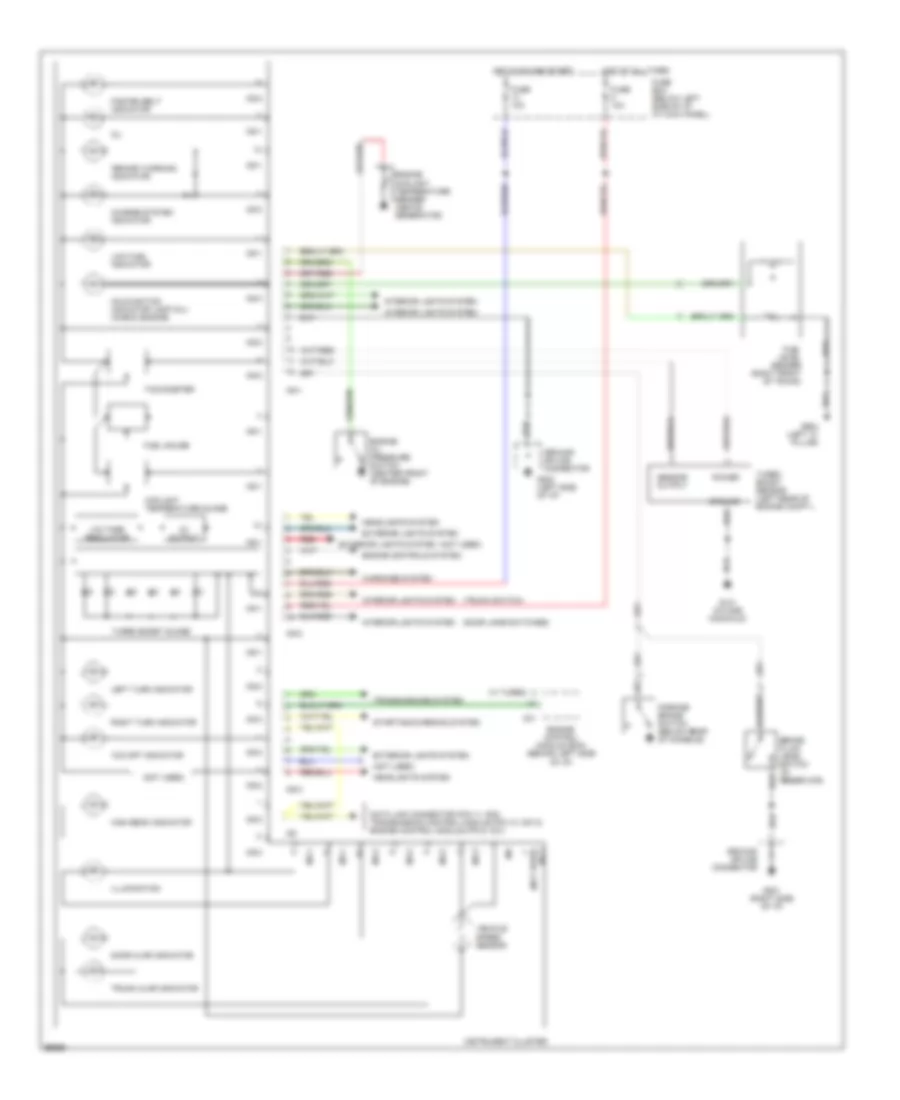
INSTRUMENT CLUSTER
Instrument Cluster Wiring Diagram for Hyundai Scoupe LS 1994
 https://portal-diagnostov.com/license.html
Automotive Electricians Portal FZCO
Automotive Electricians Portal FZCO
https://portal-diagnostov.com/license.html
https://portal-diagnostov.com/license.html
Automotive Electricians Portal FZCO
Automotive Electricians Portal FZCO
List of elements for Instrument Cluster Wiring Diagram for Hyundai Scoupe LS 1994:
- "brake" warning indicator
- "o/d off" indicator
- (door jamb switches)
- (not used)
- (not used) i05-3
- (trunk switch)
- 5v output
- Brake fluid level switch (in reservoir)
- C01
- Charge system indicator
- Coolant temperature guage
- Data link connector (pin 11, m02) transmission control module (pin 10, m07-2) engine control module (pin 9, c01)
- Door ajar indicator
- Engine control module (ecm) (behind left side of i/p)
- Engine controls system
- Engine coolant temperature sender (above generator)
- Engine oil pressure switch (center front of engine)
- Exterior lights system
- Fasten belt indicator
- Fuel gauge
- Fuel level sender (right front of trunk)
- Fuse 10a
- Fuse box (below left side of i/p, at kick panel)
- G131 (intake manifold)
- G201 (right side of i/p)
- G202 (left side of i/p)
- G904 (left "c" pillar)
- Ground
- Ground splice connector
- Headlights system
- High beam indicator
- Hot at all times
- Hot in on and start
- I05-1
- I05-2
- I05-3
- I06
- Illumination
- Instrument cluster
- Interior lights system
- Left turn indicator
- Low fuel indicator
- Malfunction indicator lamp (mil) (check engine)
- Oil
- Parking brake switch (below rear of console)
- Power
- Red
- Right turn indicator
- Sensor output
- Starting/charging system
- Tachometer
- Transmissions system
- Trunk ajar indicator
- Turbo boost guage
- Turbo boost sensor (left rear of engine compt.)
- Vehicle speed sensor
- Voltage regulator
- W/ turbo)
- Warnings system
 Čeština
 Dansk
Dansk Deutsch
 Ελληνικά
 English
 English
 Español
 Suomi
Suomi Français
 Français
 עברית
עברית Hrvatski
 Magyar
 Italiano
 日本語
日本語 한국어
한국어 Nederlands
 Polski
 Português
 Português
 Română
 Русский
 Slovenčina
 Slovenščina
 Svenska
 中文 (中国)
 Türkçe
