POWER DISTRIBUTION
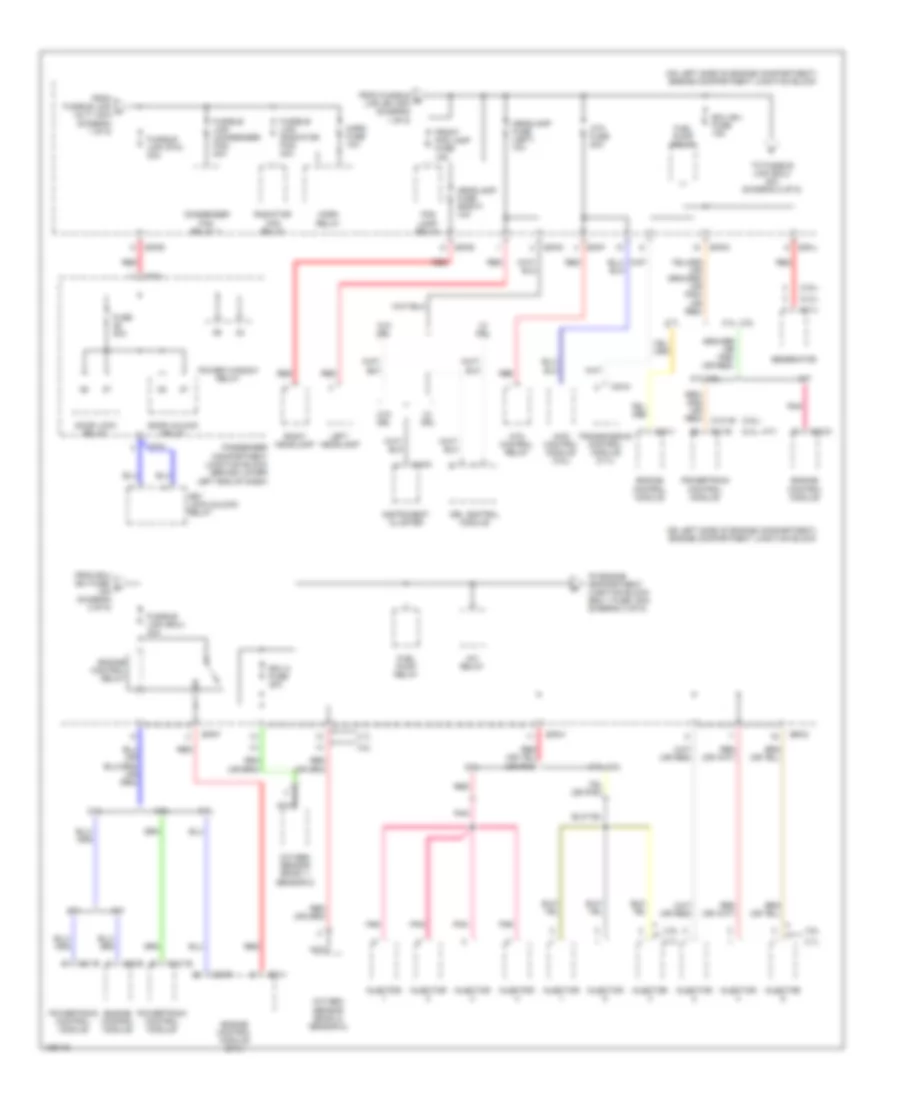
Power Distribution Wiring Diagram (1 of 5) for Hyundai Santa Fe 2004
 https://portal-diagnostov.com/license.html
Automotive Electricians Portal FZCO
Automotive Electricians Portal FZCO
https://portal-diagnostov.com/license.html
https://portal-diagnostov.com/license.html
Automotive Electricians Portal FZCO
Automotive Electricians Portal FZCO
List of elements for Power Distribution Wiring Diagram (1 of 5) for Hyundai Santa Fe 2004:
- (not used)
- (on left side of engine compartment) engine compartment junction block
- A/c fuse 10a
- A/c relay
- A/t
- Abs control module
- Acc
- Air bleeding connector
- Ashtray illumination
- Audio
- Audio head unit (delphi)
- Battery
- Blower relay
- Body ground
- C21-b
- Cigarette lighter & power outlet
- Digital clock
- E/r-a
- E/r-b
- E/r-d
- E/r-e
- Engine ground
- Ets control module
- Fuse 1 20a
- Fuse 2 10a
- Fuse 3 15a
- Fusible link (abs 1) 30a
- Fusible link (abs 2) 30a
- Fusible link (alt) 120a
- Fusible link (b+) 50a
- Fusible link (blr) 40a
- Fusible link (ign) 50a
- G08 (behind right front kick panel)
- G11 (behind left rear quarterpanel trim, near speaker)
- Generator
- I/p-d
- I/p-f
- I/p-h
- I/p-j
- I/p-l
- I/p-p
- Ignition lock switch
- Ignition switch
- Illumi- nation
- Interior lights system
- J/c m46 (at left center of floor)
- Lock
- M/t
- Nca
- Off
- Overhead console lamp
- Passenger compartment junction block (behind lower left end of dash)
- Pcm
- Pnk
- Power outlet
- Power outside mirror switch
- Rear power outlet
- Red
- St sig fuse 10a
- Start
- Start motor
- Start relay
- Start solenoid
- To fusible link (p/w) 30a (diagram 2 of 5)
- To headlamp fuse (right) 10a (diagram 2 of 5)
- To passenger compartment junction block (fuse 18, 30a) (diagram 4 of 5)
- To passenger compartment junction block (fuse 5, 10a) (diagram 3 of 5)
- To passenger compartment junction block (power connector) (diagram 5 of 5)
- Transaxle range switch
- W/ sun roof
- W/o sun roof
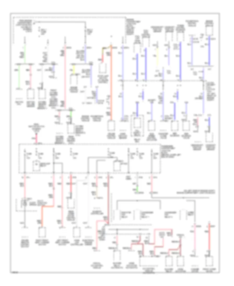
Power Distribution Wiring Diagram (2 of 5) for Hyundai Santa Fe 2004
 https://portal-diagnostov.com/license.html
Automotive Electricians Portal FZCO
Automotive Electricians Portal FZCO
https://portal-diagnostov.com/license.html
https://portal-diagnostov.com/license.html
Automotive Electricians Portal FZCO
Automotive Electricians Portal FZCOList of elements for Power Distribution Wiring Diagram (2 of 5) for Hyundai Santa Fe 2004:
- (2.4l)
- (2.4l, a/t)
- (2.7l)
- (3.5l)
- (on left side of engine compartment) engine compartment junction block
- (or red)
- 2.4l
- 2.4l, 3.5l
- 2.7l
- 2.7l, 3.5l
- 3.5l
- 4wd control module (3.5l)
- A/c relay
- A/t
- A/t, 3.5l
- Atm control relay
- Atm fuse 20a
- C121-b
- C21-b
- C22-b
- C22-d
- C23-p
- C23-v
- C24-2
- Condenser fan relay 1
- Door lock relay
- Door unlock relay
- Drl control module
- E/r-b
- E/r-d
- E/r-e
- E/r-f
- E/r-g
- E/r-h
- E/r-j
- Ecu (b+) fuse 15a
- Ecu 2 fuse 20a
- Engine control module
- Engine control module (2.7l)
- Engine control relay
- Fog lamp relay
- From ecu (b+) fuse, f 15a (diagram 2 of 5)
- From fusible b link (b+) 50a (diagram 1 of 5)
- From fusible link a (alt) 120a (diagram 1 of 5)
- Front fog lamp fuse 15a
- Fuel pump relay
- Fuse 20a
- Fusible link (condenser fan) 20a
- Fusible link (ecu) 40a
- Fusible link (p/w) 30a
- Fusible link (radiator fan) 40a
- Generator
- Headlamp fuse (left) 10a
- Headlamp fuse (right) 10a
- Horn fuse 10a
- Horn relay
- I/p-a
- I/p-m
- Injector
- Instrument cluster
- Key lock/unlock relay
- Left headlamp
- M/t
- M15-5
- Nca
- Oxygen sensor (bank 1/ sensor 2)
- Oxygen sensor (bank 2/ sensor 2)
- Passenger compartment junction block (behind lower left end of dash)
- Pnk
- Power window relay
- Powertrain control module
- Radiator fan relay
- Red
- Right headlamp
- To engine compartment junction block (ecu 1 fuse, 20a) (diagram 3 of 5)
- To fusible link (ecu) 40a (diagram 2 of 5)
- Transmission control module (2.7l)
- W/ drl
- W/o drl
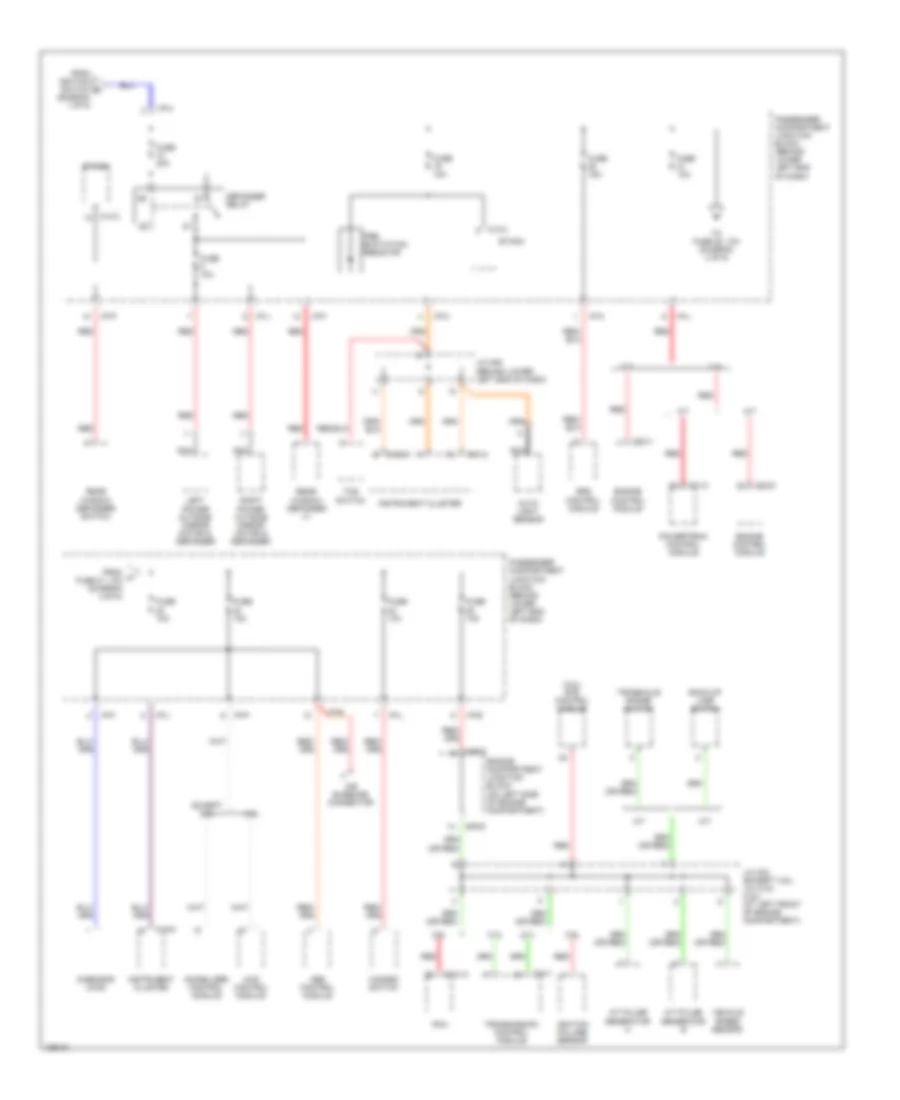
Power Distribution Wiring Diagram (3 of 5) for Hyundai Santa Fe 2004
 https://portal-diagnostov.com/license.html
Automotive Electricians Portal FZCO
Automotive Electricians Portal FZCO
https://portal-diagnostov.com/license.html
https://portal-diagnostov.com/license.html
Automotive Electricians Portal FZCO
Automotive Electricians Portal FZCOList of elements for Power Distribution Wiring Diagram (3 of 5) for Hyundai Santa Fe 2004:
- (2.7l)
- (3.5l)
- (3.5l) ets control module
- (3.5l) limp home valve
- (3.5l,
- (3.5l, 2.4l)
- (except
- (not used)
- (on left side of engine compt) engine compartment junction block
- 2.4l
- 2.4l) (2.7l)
- 2.4l, 3.5l
- 2.7l
- 3.5l
- 3.5l)
- 3.5l, 2.4l
- A/c control module (automatic)
- A/t
- Auto- matic a/c
- Blower relay
- Blower relay (automatic)
- C121-b
- C21-b
- C22-a
- C23-v
- Camshaft position sensor
- Canister close valve
- Clock spring
- Condenser fan relay 1
- Condenser fan relay 2
- Crankshaft position sensor
- Cruise control module
- Cruise remote control switch
- E/r-c
- E/r-e
- E/r-f
- E/r-g
- E/r-h
- Ecu 1 fuse 20a
- Ecu 3 fuse 10a
- Egr solenoid
- Egr solenoid valve
- Electrical chrome mirror
- Engine compartment junction block (on left side of engine compt)
- Engine control module
- Etacm
- Except 3.5l
- Fail safety relay
- From engine compartment g junction block (a/c relay) (diagram 2 of 5)
- From ignition switch (diagram 1 of 5)
- Front oxygen sensor (2.4l) oxygen sensor (bank 2/ sensor 1) (3.5l)
- Front wiper motor
- Fuse 10a
- Fuse 20a
- Fuse 25a
- Headlamp relay
- Home link controller
- I/p-a
- I/p-b
- I/p-d
- I/p-e
- I/p-h
- I/p-j
- I/p-l
- Idle speed control actuator
- Ignition coil
- Ignition failure sensor
- J/c c33 (except 3.5l) j/c c133 (3.5l) (at left front of engine compt)
- J/c m04 (behind lower left end of dash)
- Left front seat warmer switch
- M/t
- M13-3
- M20-3
- M32-1
- M87-2
- Manual a/c
- Manual a/c control module
- Mass air flow sensor
- Mode actuator
- Mode actuator (automatic)
- Multi- function switch
- Nca
- Oxygen sensor (bank 1/ sensor 1)
- Oxygen sensor (bank 1/ sensor 2) (3.5l)
- Oxygen sensor (bank 2/ sensor 1)
- Passenger compartment junction block (behind lower left end of dash)
- Pnk
- Powertrain control module
- Purge control solenoid valve
- Radiator fan relay
- Rear oxygen sensor (2.4l)
- Rear wiper motor control module
- Red
- Relay box
- Right front seat warmer switch
- Stop lamp switch (w/ cruise control)
- Sunroof controller
- Washer motor
- Wiper relay
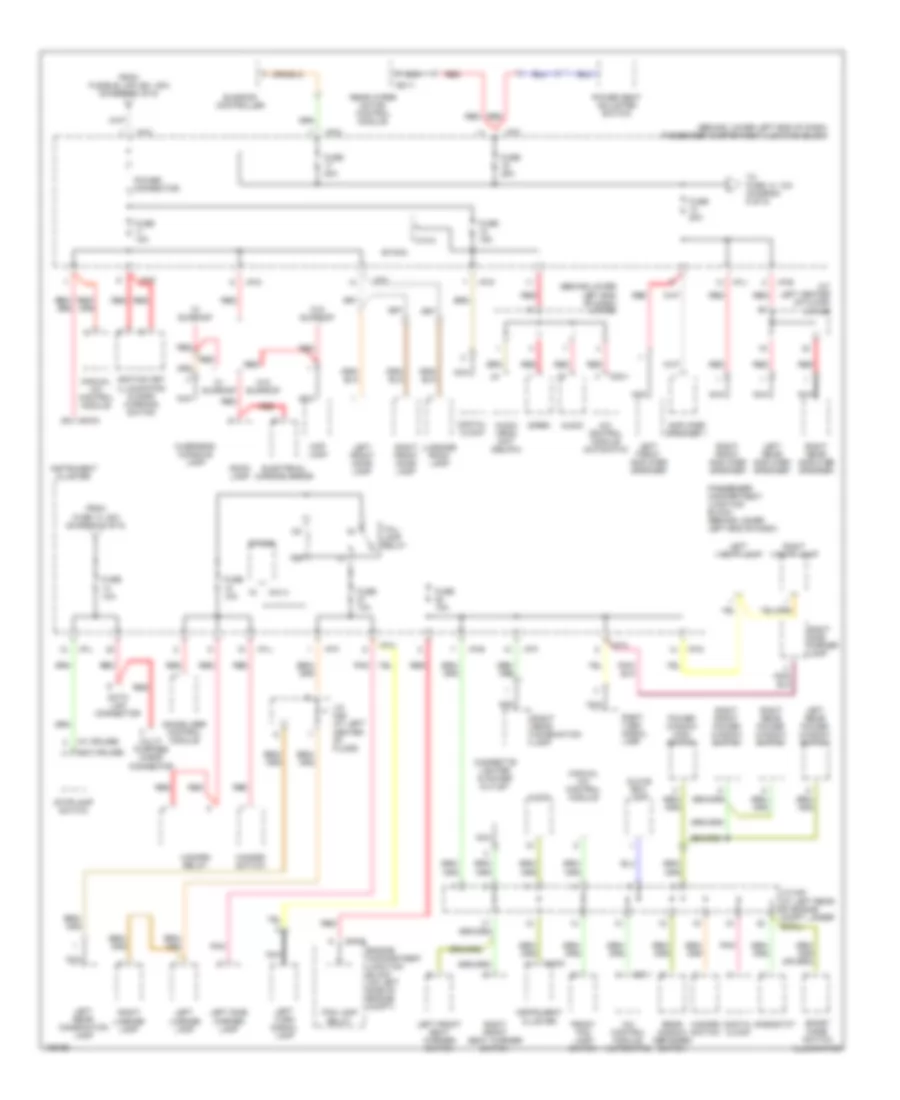
Power Distribution Wiring Diagram (4 of 5) for Hyundai Santa Fe 2004
 https://portal-diagnostov.com/license.html
Automotive Electricians Portal FZCO
Automotive Electricians Portal FZCO
https://portal-diagnostov.com/license.html
https://portal-diagnostov.com/license.html
Automotive Electricians Portal FZCO
Automotive Electricians Portal FZCOList of elements for Power Distribution Wiring Diagram (4 of 5) for Hyundai Santa Fe 2004:
- (3.5l) ets control module
- (diagram 1 of 5)
- 2.4l
- 2.7l
- 3.5l
- 4wd control module
- A/t
- A/t pulse generator a
- A/t pulse generator b
- Abs control module
- Air bleeding connector
- Auto light sensor
- Back-up lamp switch
- C121-c
- C21-c
- C22-d
- C23-v
- C24-1
- Defogger relay
- E/r-d
- E/r-g
- Engine compartment junction block (on left side of engine compartment)
- Engine control module
- Etacm
- Except 3.5l
- From h fuse 21, 10a (diagram 4 of 5)
- From ignition switch d
- Fuse 10a
- Fuse 15a
- Fuse 30a
- G-sensor (4wd)
- Hazard switch
- I/p-b
- I/p-f
- I/p-h
- I/p-j
- I/p-k
- I/p-l
- I/p-m
- I/p-p
- Ignition failure sensor
- Immobilizer control module
- Instrument cluster
- J/c c33 (except 3.5l) j/c c133 (3.5l) (at left front of engine compartment)
- J/c m05 (behind lower left end of dash)
- Left power outside mirror motor & defogger
- M/t
- M13-3
- M15-5
- M15-6
- Nca
- Passenger compartment junction block (behind lower left end of dash)
- Pcm
- Powertrain control module
- Pre- excitation resistor
- Rear window defogger (+)
- Rear window defogger switch
- Red
- Right power outside mirror motor & defogger
- Srs control module
- Tcs switch
- To fuse 22, 10a (diagram 4 of 5)
- Transaxle range switch
- Transmission control module
- Vehicle speed sensor
Power Distribution Wiring Diagram (5 of 5) for Hyundai Santa Fe 2004
 https://portal-diagnostov.com/license.html
Automotive Electricians Portal FZCO
Automotive Electricians Portal FZCO
https://portal-diagnostov.com/license.html
https://portal-diagnostov.com/license.html
Automotive Electricians Portal FZCO
Automotive Electricians Portal FZCOList of elements for Power Distribution Wiring Diagram (5 of 5) for Hyundai Santa Fe 2004:
- (at left center of floor) j/c m46
- (behind lower left end of dash) j/c m05
- (behind lower left end of dash) passenger compartment junction block
- (w/ cruise)
- (w/o cruise)
- A/c control module (automatic)
- Amplifier speaker 1
- Audio
- Audio head unit (delphi)
- Cigarette lighter & power outlet
- Data link connector
- Digital clock
- E/r-e
- Electrical chrome mirror
- Engine compartment junction block (on left side of engine compt)
- Etacm
- Fog lamp relay
- From fuse 13, 20a (diagram 5 of 5)
- From fusible link (b+), 50a (diagram 1 of 5)
- Front fog lamp switch
- Fuse 10a
- Fuse 15a
- Fuse 20a
- Fuse 25a
- Glove box lamp
- Hazard relay
- Hazard switch
- I/p-a
- I/p-b
- I/p-c
- I/p-d
- I/p-e
- I/p-f
- I/p-j
- I/p-l
- I/p-p
- Ignition key illumination & door warning switch
- Immobilizer control module
- Instrument cluster
- J/c m40 (at left rear of engine compt, under cowl)
- J/c m46 (at left center of floor)
- Left front amplifier speaker
- Left front door lamp
- Left front seat warmer switch
- Left license lamp
- Left rear amplifier speaker
- Left rear combination lamp
- Left rear power window switch
- Left side marker lamp
- Left turn signal lamp
- Left vanity lamp
- Luggage room lamp
- M13-3
- M15-5
- M15-6
- M32-1
- Manual a/c control module
- Map lamp
- Multi- purpose check connector
- Nca
- Overhead console lamp
- Passenger compartment junction block (behind lower left end of dash)
- Pnk
- Power connector
- Power seat adjuster switch
- Power window main switch
- R07-1
- Rear window defogger switch
- Rear wiper motor control module
- Red
- Rheostat
- Right front amplifier speaker
- Right front door lamp
- Right front power window switch
- Right front seat warmer switch
- Right license lamp
- Right rear amplifier speaker
- Right rear combination lamp
- Right rear power window switch
- Right side marker lamp
- Right turn signal lamp
- Right vanity lamp
- Room lamp
- Siren
- Sport mode switch illumination
- Stoplamp switch
- Sunroof controller
- Tail- lamp relay
- To fuse 14, 10a (diagram 5 of 5)
- W/ sunroof
- W/o sunroof

 Čeština
 Dansk
Dansk Deutsch
 Ελληνικά
 English
 English
 Español
 Suomi
Suomi Français
 Français
 עברית
עברית Hrvatski
 Magyar
 Italiano
 日本語
日本語 한국어
한국어 Nederlands
 Polski
 Português
 Português
 Română
 Русский
 Slovenčina
 Slovenščina
 Svenska
 中文 (中国)
