
 Čeština
 Dansk
Dansk Deutsch
 Ελληνικά
 English
 English
 Español
 Suomi
Suomi Français
 Français
 עברית
עברית Hrvatski
 Magyar
 Italiano
 日本語
日本語 한국어
한국어 Nederlands
 Polski
 Português
 Português
 Română
 Русский
 Slovenčina
 Slovenščina
 Svenska
 中文 (中国)

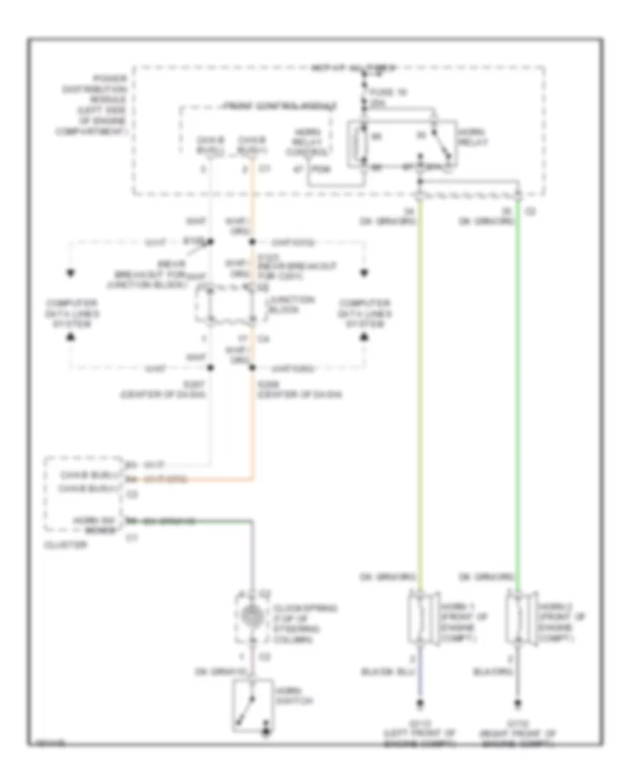
HORN
Horn Wiring Diagram for Dodge Durango 2004
List of elements for Horn Wiring Diagram for Dodge Durango 2004:

ANTI-LOCK BRAKESBODY CONTROL MODULESANTI-THEFTAIR CONDITIONINGCOOLING FANCRUISE CONTROLDEFOGGERSENGINE PERFORMANCECOMPUTER DATA LINESGROUND DISTRIBUTIONEXTERIOR LIGHTSHEADLIGHTSHORNINTERIOR LIGHTSINSTRUMENT CLUSTERPOWER DISTRIBUTIONPOWER SEATSPOWER DOOR LOCKSMEMORY SYSTEMSPOWER WINDOWSPOWER MIRRORSRADIOSHIFT INTERLOCKSTARTING/CHARGINGPOWER TOP/SUNROOFTRANSMISSIONSUPPLEMENTAL RESTRAINTSWARNING SYSTEMSWIPER/WASHER