ANTI-LOCK BRAKES
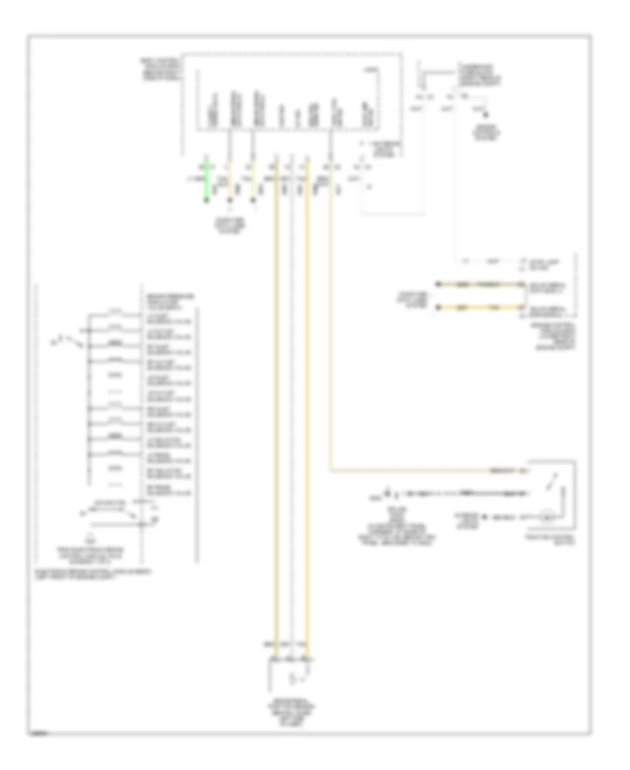
Anti-lock Brakes Wiring Diagram (1 of 2) for Cadillac XLR V 2007
 https://portal-diagnostov.com/license.html
Automotive Electricians Portal FZCO
Automotive Electricians Portal FZCO
https://portal-diagnostov.com/license.html
https://portal-diagnostov.com/license.html
Automotive Electricians Portal FZCO
Automotive Electricians Portal FZCO
List of elements for Anti-lock Brakes Wiring Diagram (1 of 2) for Cadillac XLR V 2007:
- (in engine harness, approximately 12.0 cm from ebcm breakout) s191
- (in instrument panel harness, approximately 10.5 cm from break out to yaw & lateral acceleration sensor)
- (in instrument panel harness, approximately 6.5 cm from break out to accelerator pedal position sensor)
- (lower left side of engine, above generator) g105
- 5v ref
- A10
- A11
- A12
- A13
- A14
- Abs fuse 27 60a
- Abs ind
- Abs/mrrtd/afs fuse 1 10a
- Accelerometer lateral
- B10
- B11
- B12
- B13
- B14
- B16
- Bat
- Brake fluid level switch (in brake fluid reservoir)
- Brake fluid pressure sensor (on brake pressure modulator valve)
- Brake ind
- Brk fluid lvl sens signal
- Brk fluid press sens sig
- C10
- C11
- C12
- C13
- C14
- Computer data lines system
- Electronic brake control module (ebcm) (left front of engine compt)
- Electronic power steering system
- F10
- F11
- G101
- Gmlan
- Gmlan serial data (+)
- Gmlan serial data (-)
- Ground
- Hot at all times
- Hot in on or start
- Ign
- Ign 1 voltage
- Instrument panel cluster (ipc)
- Ipc
- Ipc class 2 serial data
- Lateral accelerometer sig
- Left front wheel speed sensor (at left front hub assembly)
- Left rear wheel speed sensor (at left rear hub assembly)
- Lf wheel sens sig
- Logic
- Low ref
- Lr spd sens sig
- Message center
- Message request
- Pnk
- Power distribution system
- Red
- Rf spd sens sig
- Right front wheel speed sensor (at right front hub assembly)
- Right rear wheel speed sensor (at right rear hub assembly)
- Rr spd sens sig
- S193 (in engine harness, approximately 10.5 cm from ebcm breakout)
- S195
- S238
- S244
- Sensor
- Splice pack sp101 (in forward lamp harness, in engine compt, on upper left frame rail, grounded to g101)
- Steering angle sensor
- Strg whl pos sig a
- Strg whl pos sig b
- Strng wheel pos sig a
- Strng wheel pos sig b
- Tan
- To brake pressure modulator valve (diagram 2 of 2)
- Traction control ind
- Underhood fuse block (right rear of engine compt)
- Var eff strg act sup volt
- Var effort steering act ctrl
- Yaw & lateral accelerometer sensor (behind center of dash)
- Yaw rate sens sig
- Yaw rate sens sig (1)
Anti-lock Brakes Wiring Diagram (2 of 2) for Cadillac XLR V 2007
 https://portal-diagnostov.com/license.html
Automotive Electricians Portal FZCO
Automotive Electricians Portal FZCO
https://portal-diagnostov.com/license.html
https://portal-diagnostov.com/license.html
Automotive Electricians Portal FZCO
Automotive Electricians Portal FZCOList of elements for Anti-lock Brakes Wiring Diagram (2 of 2) for Cadillac XLR V 2007:
- 5v ref
- Body control module (bcm) (behind right side of dash)
- Brake pedal position sensor (behind lower left side of dash)
- Brake pressure modulator valve (bpmv)
- Brk pos sens sig
- C3 a4
- C4 c4
- Class 2 serial data
- Computer data lines system
- Data bus (-) gmlan serial
- Electronic brake control module (ebcm) (left front of engine compt)
- Engine control module (ecm) (lower right rear of engine compt)
- Engine controls system
- Exterior lights system
- From electronic brake control module, pin e (diagram 1 of 2)
- G202
- Gmlan serial data bus (+)
- Gmlan serial data bus (-) c3
- Interior lights system
- Lf inlet solenoid valve
- Lf isolation solenoid valve
- Lf outlet solenoid valve
- Lf prime solenoid valve
- Logic
- Low ref
- Lr inlet solenoid valve
- Lr outlet solenoid valve
- Motor ctrl
- Rf inlet solenoid valve
- Rf isolation solenoid valve
- Rf outlet solenoid valve
- Rf prime solenoid valve
- Rr inlet solenoid valve
- Rr outlet solenoid valve
- S246
- Splice pack sp202 (in instrument panel harness, at base of right "a" pillar, behind trim panel, grounded to g202)
- Stop lamp sw sig c1
- Stop lmp sw sig
- Tan
- Trac ctrl sw sig
- Traction control switch
- Underhood fuse block (right rear of engine compt)

 Čeština
 Dansk
Dansk Deutsch
 Ελληνικά
 English
 English
 Español
 Suomi
Suomi Français
 Français
 עברית
עברית Hrvatski
 Magyar
 Italiano
 日本語
日本語 한국어
한국어 Nederlands
 Polski
 Português
 Português
 Română
 Русский
 Slovenčina
 Slovenščina
 Svenska
 中文 (中国)
