ENGINE PERFORMANCE
3.5L
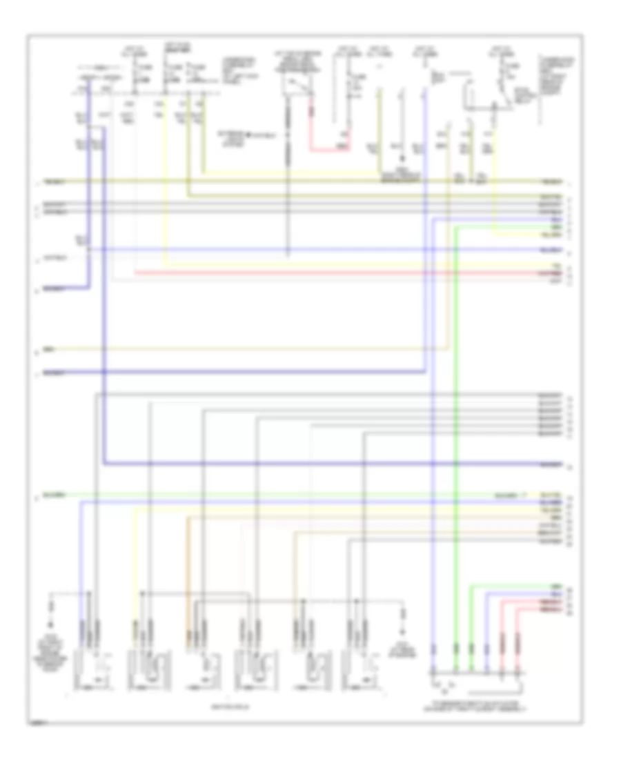
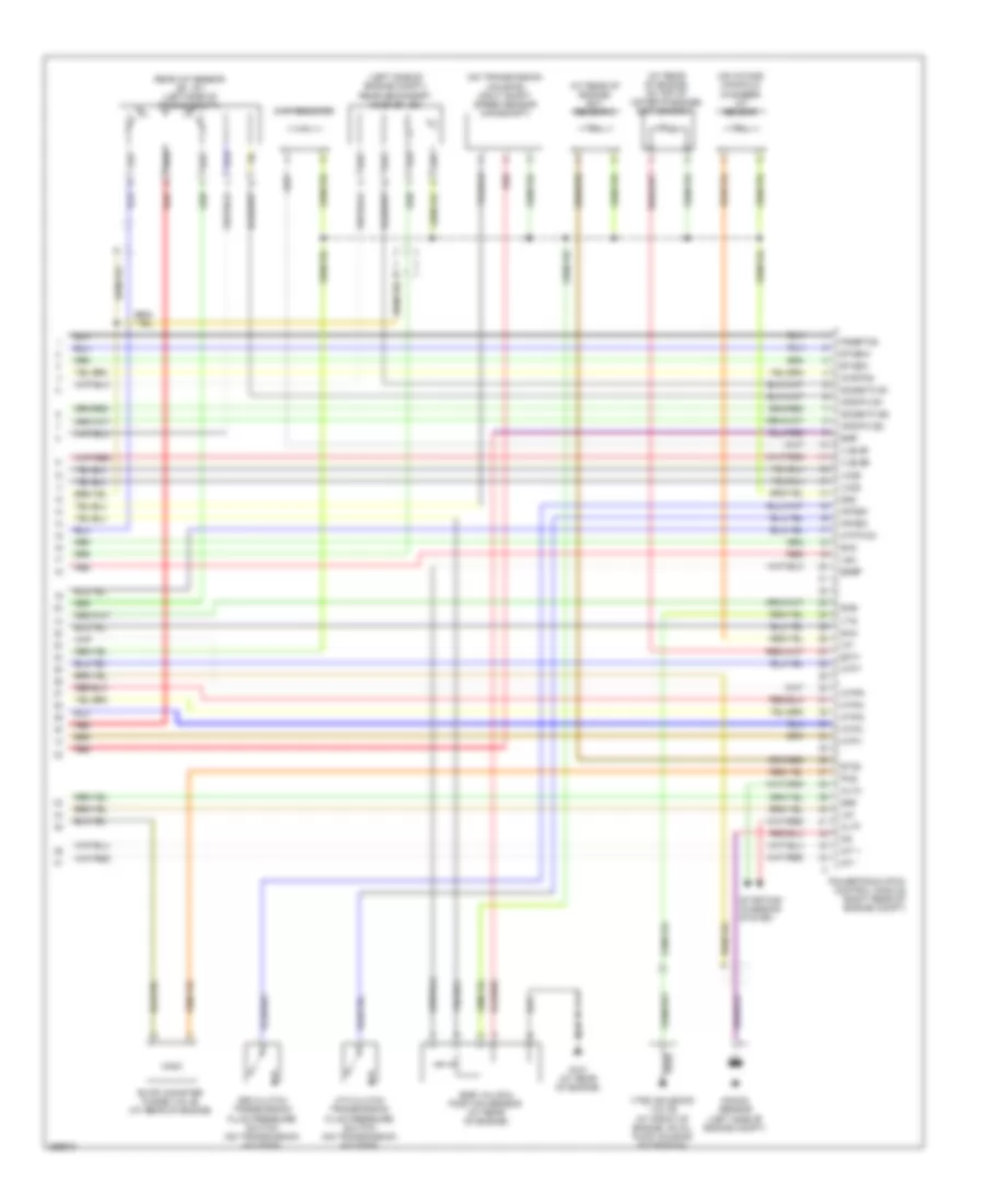
3.5L, Engine Performance Wiring Diagram (1 of 6) for Honda Ridgeline RTL 2008
 https://portal-diagnostov.com/license.html
Automotive Electricians Portal FZCO
Automotive Electricians Portal FZCO
https://portal-diagnostov.com/license.html
https://portal-diagnostov.com/license.html
Automotive Electricians Portal FZCO
Automotive Electricians Portal FZCO
List of elements for 3.5L, Engine Performance Wiring Diagram (1 of 6) for Honda Ridgeline RTL 2008:
- (in fuel tank) fuel pump
- (not used)
- A/f sensor relay
- Acc
- Afshtcr
- Air conditioning system
- Anti- theft system
- Anti-theft system
- App sensor (right rear of engine compt)
- Aps1
- Aps2
- Atp-p
- Bksw
- Bkswnc
- Can h
- Can l
- Computer data lines system
- Computer data lines system cooling fans system
- Computer data lines system shift interlock system
- Cooling fans system
- D3 switch
- D3sw
- E13
- E16
- Eld
- Etcsrly
- Evap canister vent shut valve (under left rear of vehicle)
- Exterior lights system
- Fanh
- Fanl
- Ftp
- Ftp sensor
- Fuse 15a
- Fuse 7.5a
- G202 (right rear of engine compt)
- G401 (at left kick panel)
- G502 (behind rear seat)
- Hot at all times
- Hot in on or start
- Ignition coil relay
- Imo flr
- Imocd
- K-line
- Lg3
- Mrly
- Nep
- Pdsw
- Pgm-fi main relay 1
- Pgm-fi main relay 2
- Powertrain (pcm) control module (right rear of engine compt)
- Psp switch (on power steering pressure line)
- Pspsw
- Red
- Scs
- Sg3
- Sg4
- Sg7
- Sls
- Transmissions system (4wd circuit) navigation system
- Under-dash fuse/relay box (at left kick panel)
- Vcc3
- Vcc4
- Vcc7
- Vssout
- Vsv
- Wen
- X32
- X36
- X38
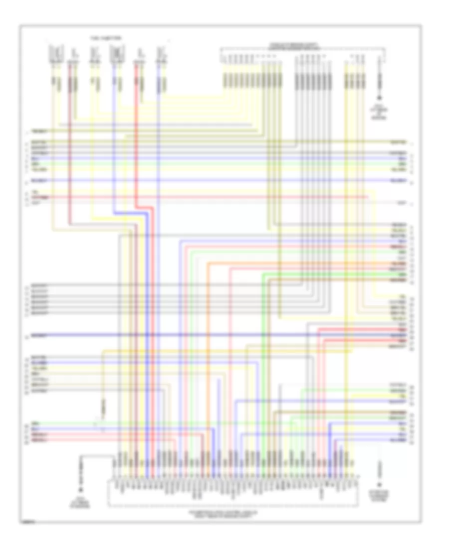
3.5L, Engine Performance Wiring Diagram (2 of 6) for Honda Ridgeline RTL 2008
 https://portal-diagnostov.com/license.html
Automotive Electricians Portal FZCO
Automotive Electricians Portal FZCO
https://portal-diagnostov.com/license.html
https://portal-diagnostov.com/license.html
Automotive Electricians Portal FZCO
Automotive Electricians Portal FZCOList of elements for 3.5L, Engine Performance Wiring Diagram (2 of 6) for Honda Ridgeline RTL 2008:
- (at top of brake pedal arm) brake pedal position switch
- Atp-p
- Atp-r
- E10
- Eld unit
- Etcs control relay
- Exterior lights system
- F17
- F19
- Fuse 15a
- Fuse 20a
- Fuse 7.5a
- G101 (at rear of engine)
- G102 (at right front of engine, near power steering pump)
- G202 (right rear of engine compt)
- Hot at all times
- Hot in on or start
- Icm
- Ignition coils
- Micu
- P16
- P20
- Red
- Tp sensor/throttle actuator (on side of throttle body assembly)
- Under-dash fuse/relay box (at left kick panel)
- Under-hood fuse/relay box (at right rear of engine compt)
- X34
- X35
3.5L, Engine Performance Wiring Diagram (3 of 6) for Honda Ridgeline RTL 2008
 https://portal-diagnostov.com/license.html
Automotive Electricians Portal FZCO
Automotive Electricians Portal FZCO
https://portal-diagnostov.com/license.html
https://portal-diagnostov.com/license.html
Automotive Electricians Portal FZCO
Automotive Electricians Portal FZCOList of elements for 3.5L, Engine Performance Wiring Diagram (3 of 6) for Honda Ridgeline RTL 2008:
- (middle of engine compt) junction connector c103
- Altl
- Ckpa
- Ckpb
- Cmp
- Fuel injectors
- G101 (at rear of engine)
- Ig1
- Igp
- Igpls1
- Igpls2
- Igpls3
- Igpls4
- Igpls5
- Igpls6
- Imtm
- Inj1
- Inj2
- Inj3
- Inj4
- Inj5
- Inj6
- Ip b1
- Ip b2
- Lg2
- Lsb
- Lsc
- Map
- Pg1
- Pg2
- Powertrain (pcm) control module (right rear of engine compt)
- Red
- Sg1
- Sg5
- Sho2s b1
- Sho2s b2
- Starting/ charging system
- Tpsa
- Tpsb
- Vbsol
- Vcc1
- Vcc5
- Vcent b1
- Vcent b2
- Vs b1
- Vs b2
- Vtpsw
3.5L, Engine Performance Wiring Diagram (4 of 6) for Honda Ridgeline RTL 2008
 https://portal-diagnostov.com/license.html
Automotive Electricians Portal FZCO
Automotive Electricians Portal FZCO
https://portal-diagnostov.com/license.html
https://portal-diagnostov.com/license.html
Automotive Electricians Portal FZCO
Automotive Electricians Portal FZCOList of elements for 3.5L, Engine Performance Wiring Diagram (4 of 6) for Honda Ridgeline RTL 2008:
- (left side of engine compt) front a/f sensor (b2, s1)
- (left side of engine compt) front secondary ho2s (b2, s2)
- (middle of engine compt) junction connector c104
- A/t clutch pressure control solenoid valve c (on transmission housing)
- Chip resistor
- Ckp sensors (a & b) (at lower front of engine)
- Cmp sensor (on top front of engine)
- G101 (at rear of engine)
- Map sensor (on top of throttle body assembly)
- Output shaft speed sensor (countershaft) (on transmission housing)
- Red
- Torque converter clutch solenoid valve
- Vtec oil pressure switch (on lower front of engine)
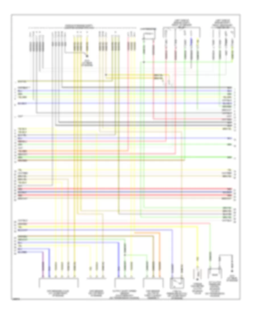
3.5L, Engine Performance Wiring Diagram (5 of 6) for Honda Ridgeline RTL 2008
 https://portal-diagnostov.com/license.html
Automotive Electricians Portal FZCO
Automotive Electricians Portal FZCO
https://portal-diagnostov.com/license.html
https://portal-diagnostov.com/license.html
Automotive Electricians Portal FZCO
Automotive Electricians Portal FZCOList of elements for 3.5L, Engine Performance Wiring Diagram (5 of 6) for Honda Ridgeline RTL 2008:
- (on transmission housing) transmission range switch
- (right rear of engine) junction connector c105
- A/t clutch pressure control solenoid valve a (on transmission housing)
- A/t clutch pressure control solenoid valve b (on transmission housing)
- A/t gear position indicator drive circuit
- A/t gear position indicator/ cruise control dimming circuit
- A19
- A20
- Atf temperature sensor (on transmission housing)
- Computer data lines system
- Fast controller area network
- G101 (at rear of engine)
- Gauge control module
- Imt valve (upper front of engine)
- Mil ind
- Pnk
- Red
- Shift control solenoid valve a
- Shift control solenoid valve b
- Shift control solenoid valve c
- Starting/ charging system
- Transceiver
- Warning drive control
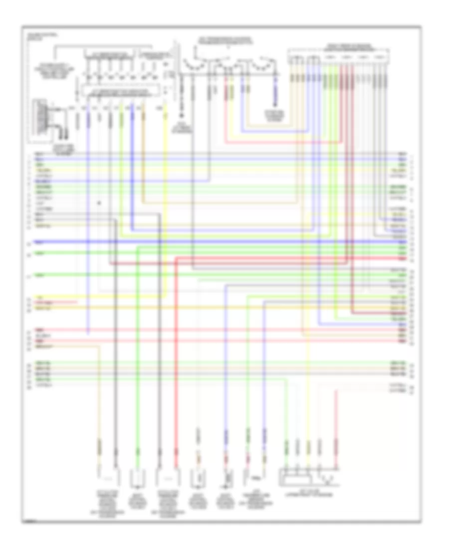
3.5L, Engine Performance Wiring Diagram (6 of 6) for Honda Ridgeline RTL 2008
 https://portal-diagnostov.com/license.html
Automotive Electricians Portal FZCO
Automotive Electricians Portal FZCO
https://portal-diagnostov.com/license.html
https://portal-diagnostov.com/license.html
Automotive Electricians Portal FZCO
Automotive Electricians Portal FZCOList of elements for 3.5L, Engine Performance Wiring Diagram (6 of 6) for Honda Ridgeline RTL 2008:
- (at rear of engine) ect sensor 2
- (at rear of engine, on top of water passage) ect sensor 1
- (left side of engine compt) rear secondary ho2s (b1, s2)
- (on intake manifold chamber) iat sensor
- (on transmission housing) input shaft speed sensor (mainshaft)
- 3rd clutch transmission fluid pressure switch (on transmission housing)
- 4th clutch transmission fluid pressure switch (on transmission housing)
- Afshtc b1
- Afshtc b2
- Altc
- Altf
- Atft
- Atp fwd
- Atp-1
- Atp-2
- Atp-d
- Atp-n
- Atp-r
- Chip resistor
- Ect1
- Egr
- Egr valve & position sensor (at rear of engine)
- Egrp
- Etc2
- Etcsm+
- Etcsm-
- Evap canister purge valve (at rear of engine)
- G101 (at rear of engine)
- Iat
- Ig1etcs
- Imt +
- Imt -
- Knock sensor (left side of engine compt)
- Lg1
- Lsa
- Op3sw
- Op4sw
- Pcs
- Pgmetcs
- Powertrain (pcm) control module (right rear of engine compt)
- Rear a/f sensor (b1, s1) (left side of engine compt)
- Red
- Sg2
- Sg6
- Sha
- Shb
- Shc
- So2shtc b1
- So2shtc b2
- Starting/ charging system
- Vcc2
- Vcc6
- Vlblb1
- Vlblb2
- Vtec solenoid valve (at front of engine, on oil pump housing extension)
- Vts

 Čeština
 Dansk
Dansk Deutsch
 Ελληνικά
 English
 English
 Español
 Suomi
Suomi Français
 Français
 עברית
עברית Hrvatski
 Magyar
 Italiano
 日本語
日本語 한국어
한국어 Nederlands
 Polski
 Português
 Português
 Română
 Русский
 Slovenčina
 Slovenščina
 Svenska
 中文 (中国)
