INSTRUMENT CLUSTER
Instrument Cluster Wiring Diagram (1 of 3) for Honda Odyssey Touring 2009
 https://portal-diagnostov.com/license.html
Automotive Electricians Portal FZCO
Automotive Electricians Portal FZCO
https://portal-diagnostov.com/license.html
https://portal-diagnostov.com/license.html
Automotive Electricians Portal FZCO
Automotive Electricians Portal FZCO
List of elements for Instrument Cluster Wiring Diagram (1 of 3) for Honda Odyssey Touring 2009:
- (canada)
- (mid) unit
- (touring)
- 10v regulator
- 5v regulator
- A/t gear position
- A/t gear position dimming circuit
- A/t gear position ind drive circuit
- A10
- A11
- A12
- A13
- A14
- A15
- A16
- A17
- A18
- A19
- A20
- A21
- A22
- A23
- A24
- A25
- A26
- A27
- A28
- A29
- A30
- Abs ind
- Anti-lock brakes system
- B10
- B11
- B12
- B13
- B14
- Brake system ind
- Canada:dx)
- Charging system ind
- Compulsory turning-off circuit
- Compulsory turning-on circuit
- Computer data lines system
- Cruise control dimming circuit
- Cruise control ind
- Cruise control main switch ind
- Cruise control system
- Detection circuit
- Dial/car graphic/lcd brightness control and dimming circuit
- Display multi-information
- Drive circuit
- Drl ind
- Eco ind (ex-l,touring)
- Engine coolant temperature gauge
- Ex,ex-l,touring
- Exterior lights system
- Fail safe circuit
- Fast controller area network transceiver
- From beeper (diagram 3 of 3)
- Fuel gauge
- G502 (under left side of dash)
- Gauge control module
- Immobilizer system ind
- Interior lights system
- Lcd back light
- Left turn signal ind
- Low fuel ind
- Low oil pressure ind
- Low tire pressure ind
- Maintenance minder ind (lx, ex,ex-l;
- Mid brightness control and dimming circuit
- Mil ind
- Navigation system
- Pointer brightness control and dimming circuit
- Power sliding door ind (ex,ex-l)
- Red
- Right turn signal ind
- Seat belt reminder ind
- Security ind
- Security ind blinking circuit
- Side airbag cut-off ind
- Speedometer
- Srs ind
- System message ind (touring)
- Tachometer
- To beeper (diagram 3 of 3)
- Tpms ind (lx, ex,ex-l; canada:dx)
- Vsa activation ind
- Vsa system ind
- Warning drive circuit
- Washer fluid level ind (canada)
- Wiper/washer system transmissions system
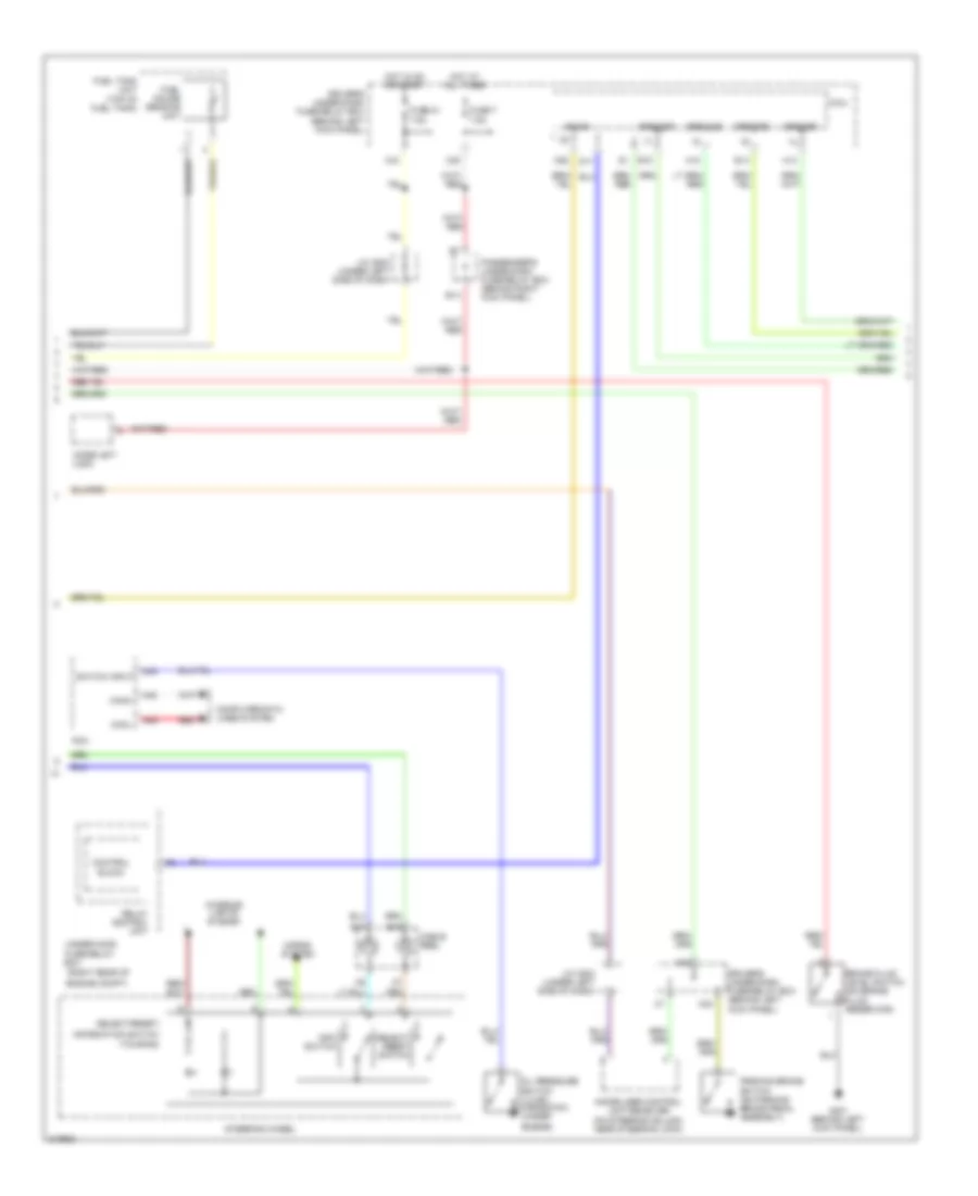
Instrument Cluster Wiring Diagram (2 of 3) for Honda Odyssey Touring 2009
 https://portal-diagnostov.com/license.html
Automotive Electricians Portal FZCO
Automotive Electricians Portal FZCO
https://portal-diagnostov.com/license.html
https://portal-diagnostov.com/license.html
Automotive Electricians Portal FZCO
Automotive Electricians Portal FZCOList of elements for Instrument Cluster Wiring Diagram (2 of 3) for Honda Odyssey Touring 2009:
- (lx,ex;
- (right rear of
- (touring)
- (under
- A48
- A49
- B-can
- B14
- B15
- Block
- Box
- Brake fluid level switch (on brake fluid reservoir)
- C45
- Cable reel
- Canada:dx)
- Canh
- Canl
- Computer data lines system
- Control
- D11
- Driver's under-dash fuse/relay box (behind left kick panel)
- Drswas
- Drswdr
- Drswra
- Drswrd
- E14
- E15
- Engine compt)
- Engine)
- Fuel gauge sending unit
- Fuel tank unit (top of fuel tank)
- Fuse 21 7.5a
- Fuse 7 7.5a
- G401 (behind left kick panel)
- H12
- H13
- Horns system
- Hot at all times
- Hot in on or start
- Immobilizer control unit-receiver (on steering column, near steering lock)
- Imoes unit (usa)
- Info switch
- Information switch
- Interior lights system
- J/c c503 (under left side of dash)
- Micu
- N28
- N30
- N34
- Oil pressure switch
- Parking brake switch (on parking brake pedal assembly)
- Passenger's under-dash fuse/relay box (behind right kick panel)
- Pcm
- Red
- Relay control unit
- Select/ reset switch
- Select/reset/
- Steering wheel
- Switch input
- Under-hood fuse/relay
- X34
- X35
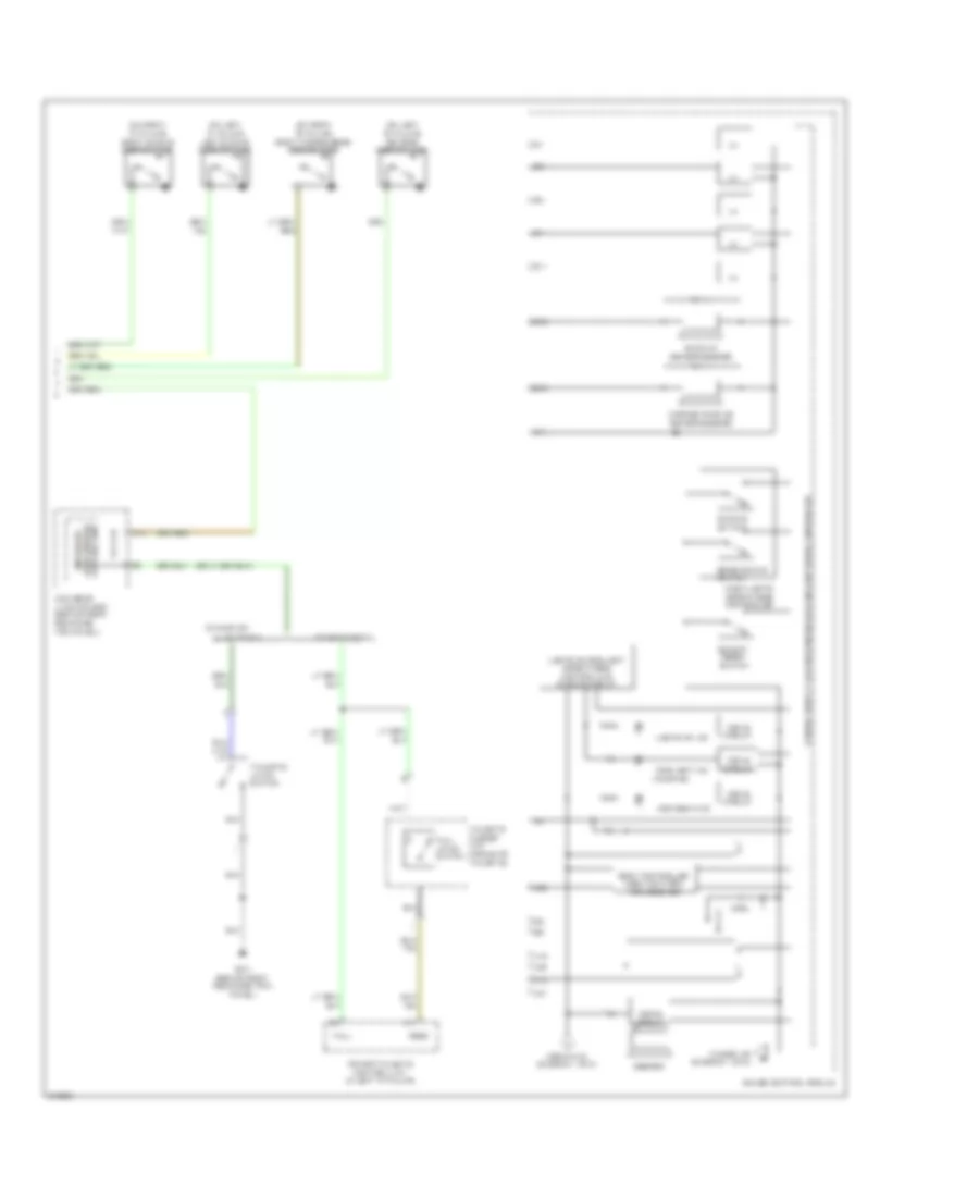
Instrument Cluster Wiring Diagram (3 of 3) for Honda Odyssey Touring 2009
 https://portal-diagnostov.com/license.html
Automotive Electricians Portal FZCO
Automotive Electricians Portal FZCO
https://portal-diagnostov.com/license.html
https://portal-diagnostov.com/license.html
Automotive Electricians Portal FZCO
Automotive Electricians Portal FZCOList of elements for Instrument Cluster Wiring Diagram (3 of 3) for Honda Odyssey Touring 2009:
- (on left "b" pillar) driver's door switch
- (on left "c" pillar) left sliding door switch
- (on right "b" pillar) front passenger's door switch
- (on right "c" pillar) right sliding door switch
- (touring)
- A14
- A18
- A19
- A20
- A21
- A25
- B11
- B12
- B13
- B14
- Back-up sensor beeper
- Beeper
- Body controller area network transceiver
- Brightening switch
- C11
- Canada:dx;
- Control unit junction box micu-rear
- Corner parking sensor beeper
- Dash lights brightness controller
- Dimming switch
- Drive circuit
- Fog light ind
- From pin 6 (diagram 1 of 3)
- Full
- Full latch switch
- G701 (behind right rear side trim panel)
- Gauge control module
- High beam ind
- I/f
- Lights on ind
- Lights on/fog light brightness control and dimming circuit
- Lx, ex,'08:ex-l
- Micu-rear junction box (behind right rear side trim panel)
- Power tailgate control unit (in left "d" pillar)
- Seg3
- Select/ reset switch
- Tailgate closer unit (middle of tailgate)
- Tailgate latch switch
- To srs ind (diagram 1 of 3)
- Touring;'09:ex-l

 Čeština
 Dansk
Dansk Deutsch
 Ελληνικά
 English
 English
 Español
 Suomi
Suomi Français
 Français
 עברית
עברית Hrvatski
 Magyar
 Italiano
 日本語
日本語 한국어
한국어 Nederlands
 Polski
 Português
 Português
 Română
 Русский
 Slovenčina
 Slovenščina
 Svenska
 中文 (中国)
