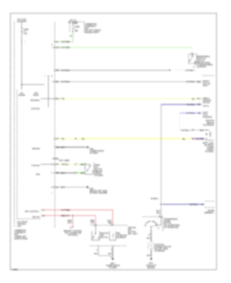
SHIFT INTERLOCK
Shift Interlock Wiring Diagram for Honda Element LX 2004
 https://portal-diagnostov.com/license.html
Automotive Electricians Portal FZCO
Automotive Electricians Portal FZCO
https://portal-diagnostov.com/license.html
https://portal-diagnostov.com/license.html
Automotive Electricians Portal FZCO
Automotive Electricians Portal FZCO
List of elements for Shift Interlock Wiring Diagram for Honda Element LX 2004:
- (bksw) switch input
- (not used)
- (sefmj) communi- cation
- Acc radio
- Atp -n
- Brake pedal position switch (behind dash, on brake pedal support)
- Bus (ecu)
- D10
- D11
- E10
- E13
- E22
- Ecm/pcm (behind glove box)
- Fuse 15a
- Fuse 7.5a
- G101 (middle of engine)
- G301 (behind left side of front bumper)
- G401 (under middle of dash)
- G451 (under middle of dash)
- Gauge assembly
- Gnd
- Ground
- Hot at all times
- Hot in on or start
- Ig1 meter
- Ignition key switch
- Ignition key switch/ key light
- Junction connector c106 (on left side of engine)
- Key interlock solenoid
- Key lock sol +
- Key sw
- Multiplex control unit
- O12
- P pin sw
- Park pin switch (behind middle of dash)
- Security control unit connector (optional)
- Shift lock solenoid
- Shift lock solenoid (under middle of dash)
- Stop sw
- Transmission range switch (on lower rear of transaxle)
- Underdash fuse/relay box (under left side of dash)
- Underhood fuse/relay box (on left side of engine compt)
 Čeština
 Dansk
Dansk Deutsch
 Ελληνικά
 English
 English
 Español
 Suomi
Suomi Français
 Français
 עברית
עברית Hrvatski
 Magyar
 Italiano
 日本語
日本語 한국어
한국어 Nederlands
 Polski
 Português
 Português
 Română
 Русский
 Slovenčina
 Slovenščina
 Svenska
 中文 (中国)
 Türkçe
