AIR CONDITIONING
Automatic A/C Wiring Diagram (1 of 3) for Ford F-150 XLT 2013
 https://portal-diagnostov.com/license.html
Automotive Electricians Portal FZCO
Automotive Electricians Portal FZCO
https://portal-diagnostov.com/license.html
https://portal-diagnostov.com/license.html
Automotive Electricians Portal FZCO
Automotive Electricians Portal FZCO
List of elements for Automatic A/C Wiring Diagram (1 of 3) for Ford F-150 XLT 2013:
- (left side of dash) g203
- (or ch212)
- (or ch213)
- (or vh441)
- (right side of dash) blower motor
- (w/ ambient lighting)
- 30a
- 40a
- Act fdbk
- Air inlet dr fdbk
- Autolamp sensor in
- Autolamp/sunload sensor (center of dash)
- Battery junction box (bjb) (front of engine compt)
- Blower control
- Blower motor relay
- Blower motor speed control (right side of dash)
- Body control module (right kick panel)
- C213
- C214
- C2280a
- C2280b
- C2280f
- C228a
- C228b
- C260
- C263
- Ch122
- Ch123
- Ch207
- Ch208
- Ch228
- Ch229
- Ch238
- Ch239
- Chs02
- Chs07
- Computer data lines system
- Crd02
- Defogger system
- Defrost request
- Defrost status
- Door ccw
- Door cw
- Driver sunload
- Drv heated st pwr
- Drv heater feed
- Drv st ntc sens
- Eatc hvac module
- Evap temp sen
- Front blower rly
- Fuse
- Fuse 10a
- G202 (left side of dash)
- Gd133
- Gnd
- Hot at all times
- Hot in run or start
- Hs can+
- Hs can-
- Humidity sens
- Left side temperature blend door actuator (center of dash)
- Lh111
- Mode 1 act fdbk
- Mode door 1ccw
- Mode door 1cw
- Motor +
- Motor -
- Ms can+
- Ms can-
- Pass heated st pwr
- Pass heater feed
- Pass st ntc sens
- Pass sunload
- Pwm
- Recirc ccw
- Recirc cw
- Return
- Rh111
- Right side temperature blend door actuator (right side of dash)
- S156
- S222
- S229 (main wiring harness, near breakout to passenger air bag module)
- S260
- S449
- Sbb69
- Sbp46
- Seats system
- Temp sens
- Vbatt
- Vdb04
- Vdb05
- Vdb06
- Vdb07
- Vh101
- Vh406
- Vh413
- Vh414
- Vh416
- Vh417
- Vh436
- Vh438
- Vh440
- Vhs26
- Vhs27
- Vlf14
- Vref
- W/ dual zone
- W/o dual zone
Automatic A/C Wiring Diagram (2 of 3) for Ford F-150 XLT 2013
 https://portal-diagnostov.com/license.html
Automotive Electricians Portal FZCO
Automotive Electricians Portal FZCO
https://portal-diagnostov.com/license.html
https://portal-diagnostov.com/license.html
Automotive Electricians Portal FZCO
Automotive Electricians Portal FZCOList of elements for Automatic A/C Wiring Diagram (2 of 3) for Ford F-150 XLT 2013:
- (3.5l)
- (6.2l)
- (except 3.5l)
- (except 6.2l)
- (heater blower motor wiring harness, in breakout to defrost/panel/ floor mode door actuator)
- (heater blower motor wiring harness, near breakout to defrost/panel/ floor mode door actuator)
- (main wiring harness, near breakout to passenger air bag module)
- (main wiring harness,near breakout to passenger air bag module)
- A/c clutch relay
- A/c compressor clutch field coil (a/c compressor)
- Air inlet mode door actuator (right side of dash)
- Battery junction box (bjb) (front of engine compt)
- C1010
- C192
- C263
- Computer data lines system
- Defrost/panel/floor mode door actuator (center of dash)
- Engine controls system
- Evaporator temperature sensor (right side of dash)
- Fuse 10a
- Fuse 40a 50a
- G101 (right front of engine compt)
- Hot at all times
- Hs can+
- Hs can-
- In-vehicle temperature/ humidity sensor (left side of dash)
- Instrument panel cluster (ipc)
- Pcm power relay
- S125
- S208
- S209
- S228
- S247
- Seats system
Automatic A/C Wiring Diagram (3 of 3) for Ford F-150 XLT 2013
 https://portal-diagnostov.com/license.html
Automotive Electricians Portal FZCO
Automotive Electricians Portal FZCO
https://portal-diagnostov.com/license.html
https://portal-diagnostov.com/license.html
Automotive Electricians Portal FZCO
Automotive Electricians Portal FZCOList of elements for Automatic A/C Wiring Diagram (3 of 3) for Ford F-150 XLT 2013:
- (3.5l)
- (3.5l) s113
- (3.7l)
- (5.0l & 6.2l)
- (5.0l)
- (6.2l)
- (or re454)
- (right front of of engine compt) g101
- (w/ svt raptor)
- (w/o svt raptor)
- 3.5l
- 50a
- A/c pressure transducer (right front of engine compt)
- Aat
- Accr
- Acpt
- Ambient air temperature sensor (front of engine compt)
- Battery junction box (bjb) (front of of engine compt)
- C1026
- C133
- C1381b
- C1381e
- C1551b
- C1551e
- C175b
- C175e
- C228c
- Ce607
- Cec01
- Cec02
- Ch302
- Cht
- Computer data lines system
- Cooling fan high speed relay
- Cooling fan low speed relay
- Cooling fan relay
- Cylinder head temperature sensor (rear of right cylinder head)
- Eatc hvac module
- Engine controls system
- Engine cooling fan motor 1 (behind radiator)
- Engine cooling fan motor 2 (behind radiator)
- Except 3.5l
- Fuse 25a
- Fuse 40a
- G101 (right front of of engine compt)
- G202 (left side of dash)
- Gd133
- Gnd
- Green
- Hfc
- Hot at all times
- Hs can +
- Hs can -
- Interior lights system
- Le424
- Lfc
- Pcmrc
- Powertrain control module (right rear of engine compt)
- Re405
- Re407
- Red
- Return
- Rln44
- S105
- S141 (3.5l) s162 (except 3.5l) (3.5l: engine control sensor & fuel charge wiring harness, near breakout to fuel rail pressure sensor) (except 3.5l: engine control sensor wiring harness, near breakout to c144)
- S154
- S169 (engine control sensor wiring harness, near breakout to g101)
- S169 (except 3.5l) (engine control sensor wiring harness, near breakout to g101)
- S173 (6.2l & 5.0l) (5.0l:engine control sensor & fuel charge wiring harness, near breakout to c1019) (6.2l: engine control sensor & fuel charge wiring harness, near breakout to c133)
- S183 (engine control sensor wiring harness, near breakout to engine cooling fan motor 1)
- S197 (engine control sensor wiring harness, near breakout to engine cooling fan motor 1)
- S260 (w/ ambient lighting)
- Sig rtn
- Vdb04
- Vdb05
- Ve712
- Ve750
- Vh433
- Vln44
- Vln45
- Vln46
- Vref
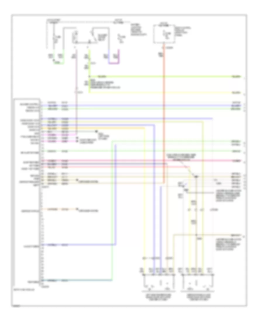
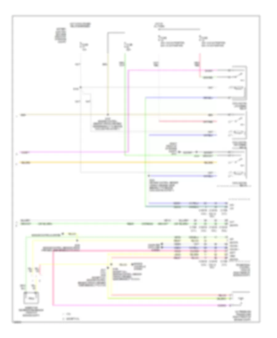
Manual A/C Wiring Diagram, Base (1 of 3) for Ford F-150 XLT 2013
 https://portal-diagnostov.com/license.html
Automotive Electricians Portal FZCO
Automotive Electricians Portal FZCO
https://portal-diagnostov.com/license.html
https://portal-diagnostov.com/license.html
Automotive Electricians Portal FZCO
Automotive Electricians Portal FZCOList of elements for Manual A/C Wiring Diagram, Base (1 of 3) for Ford F-150 XLT 2013:
- (heater blower motor wiring harness, in breakout to defrost/ panel/floor mode door actuator)
- (heater blower motor wiring harness, near breakout to defrost/panel/ floor mode door actuator) s209
- (main wiring harness, near breakout to passenger air bag module)
- Air inlet
- Autolamp sensor (center of dash)
- Autolamp sensor in
- Battery junction box (bjb) (front of engine compt)
- Blower gnd
- Blower motor (right side of dash)
- Blower motor relay
- Blower motor resistor (right side of dash)
- Body control module (right kick panel)
- C213
- C214
- C2280a
- C2280b
- C260
- C263
- C294a
- C294b
- Ch122
- Ch123
- Ch207
- Ch208
- Ch228
- Ch229
- Ch238
- Ch239
- Ch426
- Ch428
- Ch429
- Computer data lines system
- Crd02
- Defogger system
- Defrost req
- Defrost status
- Defrost/panel/floor mode door actuator (center of dash)
- Dr temp dr fdbk
- Driver temp door ccw
- Driver temp door cw
- Emtc hvac module
- Evap temp sen
- Front blower rly
- Fuse 10a
- Fuse 40a
- Fuse 5a
- G202 (left side of dash)
- G203 (left side of dash)
- Gd133
- Gd138
- Gnd
- Hot at all times
- Hot in run or start
- Humidity sens
- Lh111
- Mode door 1 ccw
- Mode door 1 cw
- Mode door 1 fdbk
- Ms can+
- Ms can-
- Recirc dr ccw
- Recirc dr cw
- Return
- Rh111
- S156
- S208
- S227 (main wiring harness, near breakout to passenger air bag module)
- S228
- S247
- Sbp46
- Solid state
- Sw high
- Sw med high
- Sw med low
- Temp sens
- Temperature blend door actuator (right side of dash)
- Vbatt
- Vdb06
- Vdb07
- Vh406
- Vh413
- Vh414
- Vh436
- Vh438
- Vh440
- Vlf14
- Vref
Manual A/C Wiring Diagram, Base (2 of 3) for Ford F-150 XLT 2013
 https://portal-diagnostov.com/license.html
Automotive Electricians Portal FZCO
Automotive Electricians Portal FZCO
https://portal-diagnostov.com/license.html
https://portal-diagnostov.com/license.html
Automotive Electricians Portal FZCO
Automotive Electricians Portal FZCOList of elements for Manual A/C Wiring Diagram, Base (2 of 3) for Ford F-150 XLT 2013:
- (6.2l)
- (except 6.2l)
- A/c clutch relay
- A/c compressor clutch field coil (a/c compressor)
- Air inlet mode door actuator (right side of dash)
- Battery junction box (bjb) (front of engine compt)
- C1010
- C192
- C263
- Computer data lines system
- Engine controls system
- Evaporator temperature sensor (right side of dash)
- Fuse 10a
- Fuse 40a (except 3.5l) 50a (3.5l)
- G101 (right front of engine compt)
- Hot at all times
- Hs can+
- Hs can-
- In-vehicle temperature/ humidity sensor (left side of dash)
- Instrument cluster
- Pcm power relay
- S125
Manual A/C Wiring Diagram, Base (3 of 3) for Ford F-150 XLT 2013
 https://portal-diagnostov.com/license.html
Automotive Electricians Portal FZCO
Automotive Electricians Portal FZCO
https://portal-diagnostov.com/license.html
https://portal-diagnostov.com/license.html
Automotive Electricians Portal FZCO
Automotive Electricians Portal FZCOList of elements for Manual A/C Wiring Diagram, Base (3 of 3) for Ford F-150 XLT 2013:
- (0r re454)
- (3.5l)
- (3.5l) s113 s173 (6.2l & 5.0l) (5.0l: engine control sensor & fuel charge wiring harness, near breakout to c1019) (6.2l: engine control sensor & fuel charge wiring harness, near breakout to c133)
- (3.7l)
- (5.0l & 6.2l)
- (5.0l)
- (6.2l)
- (engine control sensor wiring harness, near breakout to g101)
- (right front of of engine compt) g101
- (w/ svt raptor)
- (w/o svt raptor)
- 3.5l
- 50a
- A/c pressure transducer (right front of engine compt)
- Aat
- Accr
- Acpt
- Ambient air temperature sensor (front of engine compt)
- Battery junction box (bjb) (front of of engine compt)
- C1026
- C133
- C1381b
- C1381e
- C1551b
- C1551e
- C175b
- C175e
- Ce607
- Cec01
- Cec02
- Ch302
- Cht
- Computer data lines system
- Cooling fan high speed relay
- Cooling fan low speed relay
- Cooling fan relay
- Cylinder head temperature sensor (rear of right cylinder head)
- Engine controls system
- Engine cooling fan motor 1 (behind radiator)
- Engine cooling fan motor 2 (behind radiator)
- Except 3.5l
- Fuse 25a
- Fuse 40a
- G101 (right front of of engine compt)
- Hfc
- Hot at all times
- Hs can +
- Hs can -
- Le424
- Lfc
- Pcmrc
- Powertrain control module (right rear of engine compt)
- Re405
- Re407
- S105
- S154
- S162 (3.5l: engine control sensor & fuel charge wiring harness, near breakout to fuel rail pressure sensor) (except 3.5l: engine control sensor wiring harness, near breakout to c144)
- S169
- S169 (except 3.5l) (engine control sensor wiring harness, near breakout to g101)
- S183 (engine control sensor wiring harness, near breakout to engine cooling fan motor 1)
- S197 (engine control sensor wiring harness, near breakout to engine cooling fan motor 1)
- Sig rtn
- Vdb04
- Vdb05
- Ve712
- Ve750
- Vh433
- Vref
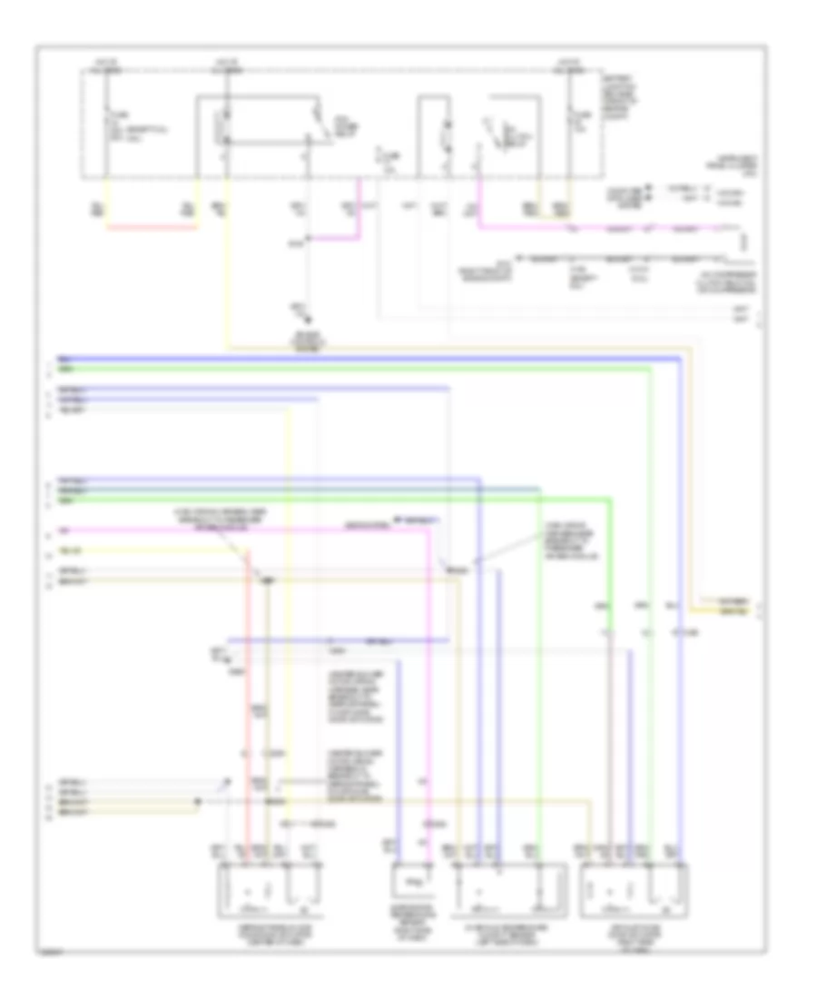
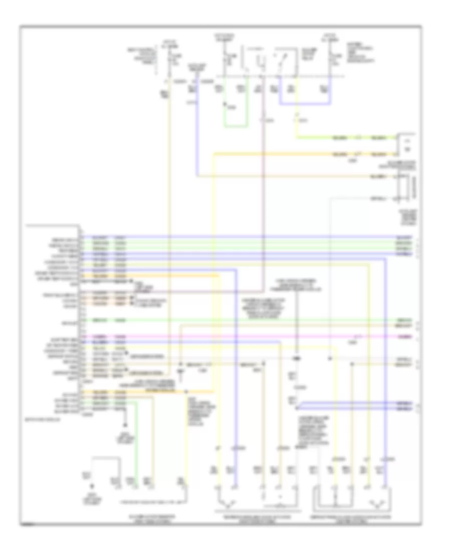
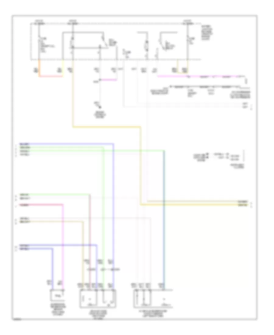
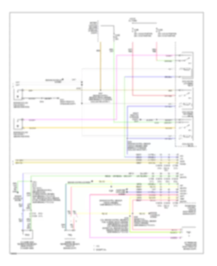
Manual A/C Wiring Diagram, Except Base (1 of 3) for Ford F-150 XLT 2013
 https://portal-diagnostov.com/license.html
Automotive Electricians Portal FZCO
Automotive Electricians Portal FZCO
https://portal-diagnostov.com/license.html
https://portal-diagnostov.com/license.html
Automotive Electricians Portal FZCO
Automotive Electricians Portal FZCOList of elements for Manual A/C Wiring Diagram, Except Base (1 of 3) for Ford F-150 XLT 2013:
- (heater blower motor wiring harness, in breakout to defrost/ panel/floor mode door actuator)
- (heater blower motor wiring harness, near breakout to defrost/ panel/floor mode door actuator)
- (main wiring harness, near breakout to passenger air bag module)
- 40a
- Act fdbk
- Air inlet dr fdbk
- Battery junction box (bjb) (front of engine compt)
- Blower control
- Blower motor relay
- Body control module (right kick panel)
- C213
- C214
- C2280a
- C2357a
- C2357b
- C263
- Ch122
- Ch123
- Ch207
- Ch208
- Ch228
- Ch229
- Ch238
- Ch239
- Computer data lines system
- Crd02
- Defogger system
- Defrost request
- Defrost status
- Defrost/panel/floor mode door actuator (center of dash)
- Door ccw
- Door cw
- Emtc hvac module
- Evap temp sen
- Ft blower relay
- Fuse
- Fuse 10a
- G202 (left side of dash)
- Gd133
- Gnd
- Hot at all times
- Hot in start or run
- Humidity sens
- Left side temperature blend door actuator (center of dash)
- Lh111
- Mode 1 act fdbk
- Mode door 1ccw
- Mode door 1cw
- Ms can+
- Ms can-
- Recirc ccw
- Recirc cw
- Return
- Rh111
- S156
- S208
- S209
- S247
- Sbp46
- Temp sens
- Vbatt
- Vdb06
- Vdb07
- Vh101
- Vh406
- Vh413
- Vh414
- Vh436
- Vh438
- Vh440
- Vref
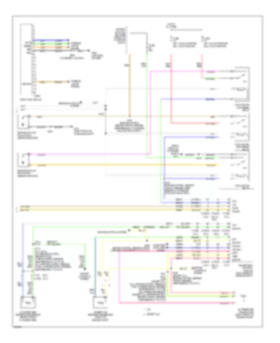
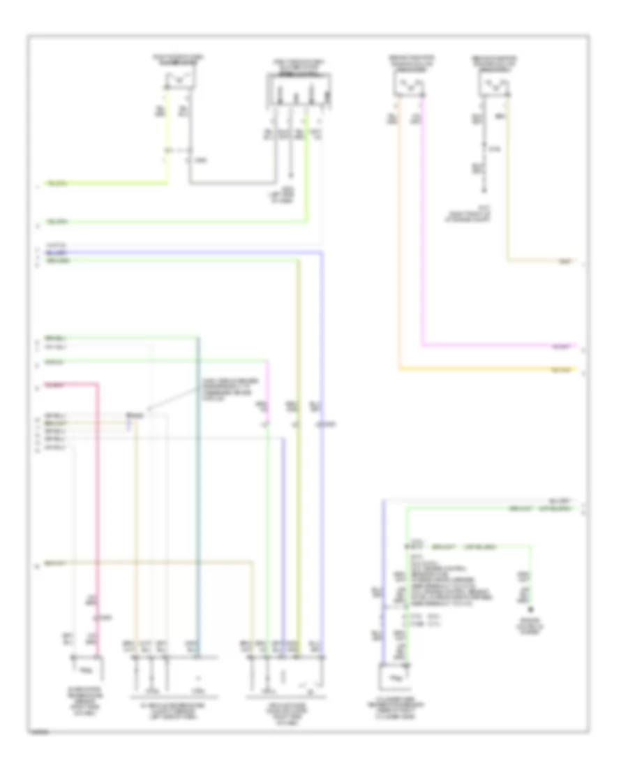
Manual A/C Wiring Diagram, Except Base (2 of 3) for Ford F-150 XLT 2013
 https://portal-diagnostov.com/license.html
Automotive Electricians Portal FZCO
Automotive Electricians Portal FZCO
https://portal-diagnostov.com/license.html
https://portal-diagnostov.com/license.html
Automotive Electricians Portal FZCO
Automotive Electricians Portal FZCOList of elements for Manual A/C Wiring Diagram, Except Base (2 of 3) for Ford F-150 XLT 2013:
- (3.5l) s113
- (3.7l)
- (6.2l)
- (behind radiator) engine cooling fan motor 1
- (behind radiator) engine cooling fan motor 2
- (main wiring harness, near breakout to passenger air bag module)
- (right side of dash) blower motor
- (right side of dash) blower motor speed control
- Air inlet mode door actuator (right side of dash)
- C1026
- C133
- C260
- C263
- Cylinder head temperature sensor (rear of right cylinder head)
- Engine controls system
- Evaporator temperature sensor (right side of dash)
- G101 (right front of of engine compt)
- G203 (left side of dash)
- Gnd
- In-vehicle temperature/ humidity sensor (left side of dash)
- Motor +
- Motor -
- Pwm
- S154
- S173 (6.2l & 5.0l) (5.0l: engine control sensor & fuel charge wiring harness, near breakout to c1019) (6.2l: engine control sensor & fuel charge wiring harness, near breakout to c133)
- S228
Manual A/C Wiring Diagram, Except Base (3 of 3) for Ford F-150 XLT 2013
 https://portal-diagnostov.com/license.html
Automotive Electricians Portal FZCO
Automotive Electricians Portal FZCO
https://portal-diagnostov.com/license.html
https://portal-diagnostov.com/license.html
Automotive Electricians Portal FZCO
Automotive Electricians Portal FZCOList of elements for Manual A/C Wiring Diagram, Except Base (3 of 3) for Ford F-150 XLT 2013:
- (3.5l)
- (3.7l)
- (5.0l & 6.2l)
- (5.0l)
- (6.2l)
- (or re454)
- (right front of of engine compt) g101
- (w/ svt raptor)
- (w/o svt raptor)
- 3.5l
- 50a
- A/c pressure transducer (right front of engine compt)
- Aat
- Acpt
- Ambient air temperature sensor (front of engine compt)
- Battery junction box (bjb) (front of of engine compt)
- C1381b
- C1381e
- C1551b
- C1551e
- C175b
- C175e
- Cec01
- Cec02
- Cht
- Computer data lines system
- Cooling fan high speed relay
- Cooling fan low speed relay
- Cooling fan relay
- Engine controls system
- Except 3.5l
- Fuse 10a
- Fuse 25a
- Fuse 40a
- Hfc
- Hot at all times
- Hot w/ pcm power relay energized
- Hs can +
- Hs can -
- Le424
- Lfc
- Powertrain control module (right rear of engine compt)
- Re405
- Re407
- S105
- S141 (3.5l) s162 (except 3.5l) (engine control sensor wiring harness, near breakout to c144)
- S154
- S169 (engine control sensor wiring harness, near breakout to g101)
- S169 (except 3.5l) (engine control sensor wiring harness, near breakout to g101)
- S183 (engine control sensor wiring harness, near breakout to engine cooling fan motor 1)
- S197 (engine control sensor wiring harness, near breakout to engine cooling fan motor 1)
- Sig rtn
- Vdb04
- Vdb05
- Ve712
- Ve750
- Vh433
- Vref

 Čeština
 Dansk
Dansk Deutsch
 Ελληνικά
 English
 English
 Español
 Suomi
Suomi Français
 Français
 עברית
עברית Hrvatski
 Magyar
 Italiano
 日本語
日本語 한국어
한국어 Nederlands
 Polski
 Português
 Português
 Română
 Русский
 Slovenčina
 Slovenščina
 Svenska
 中文 (中国)
