ANTI-LOCK BRAKES
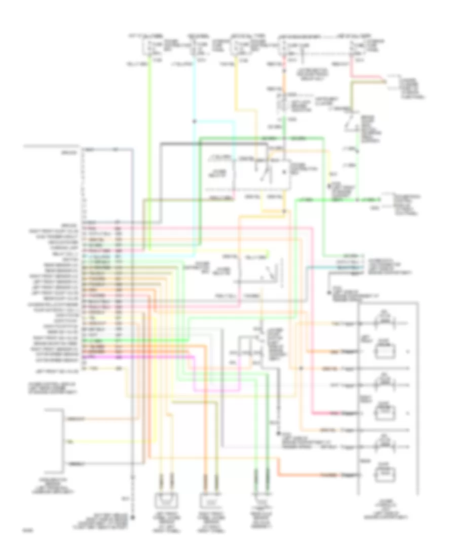
Anti-lock Brake Wiring Diagrams for Ford Explorer 1994
 https://portal-diagnostov.com/license.html
Automotive Electricians Portal FZCO
Automotive Electricians Portal FZCO
https://portal-diagnostov.com/license.html
https://portal-diagnostov.com/license.html
Automotive Electricians Portal FZCO
Automotive Electricians Portal FZCO
List of elements for Anti-lock Brake Wiring Diagrams for Ford Explorer 1994:
- (at left front wheel)
- (at right front wheel)
- 4wabs control module (left rear corner of engine compartment)
- 4wabs data link connector (left side of engine compartment)
- 4wabs hydraulic unit (left side of engine compartment)
- 4wabs pump motor (left side of engine compart- ment)
- 4wabs relay #1
- 4wabs relay #2
- Acceleration sensor (left frame rail, under driver's seat)
- Anti-lock brakes indicator
- Brake on/off (boo) switch (on brake pedal support)
- Brake on/off sw feed
- C126
- C202
- C214
- C222
- Chassis rolls database
- Diag trigger circuit
- Dump valve
- Fuse
- Fuse 10a
- Fuse 15a
- Fuse 30a
- G-switch #1
- G-switch status
- G104 (left side of engine comparment at fender apron)
- G104 (left side of engine compartment at fender apron)
- G108 (left front of engine compart- ment)
- Ground
- Hazard flasher (part of interior fuse panel)
- Hot at all times
- Hot in run
- Hot in run or start
- Ignition
- Instrument cluster
- Interior fuse panel
- Iso valve
- Left front
- Left front dump valve
- Left front iso valve
- Left front sensor (hi)
- Left front sensor (lo)
- Left front wheel 4wabs sensor
- Limited edition and electronic group only
- Motor speed sens #1
- Motor speed sens #2
- Nca
- Pnk
- Power distribution box
- Powertrain control module (at right kick panel)
- Pump motor rly coil (-) g-switch #2
- Rear
- Rear axle sensor (on axle assembly)
- Rear dump valve
- Rear iso valve
- Rear sensor (hi)
- Rear sensor (lo)
- Relay coil (-)
- Right front
- Right front dump valve
- Right front iso valve
- Right front sensor (hi)
- Right front sensor (lo)
- Right front wheel 4wabs sensor
- Tan
- Tan/red
- Vehicle power
- Warning lamp
 Čeština
 Dansk
Dansk Deutsch
 Ελληνικά
 English
 English
 Español
 Suomi
Suomi Français
 Français
 עברית
עברית Hrvatski
 Magyar
 Italiano
 日本語
日本語 한국어
한국어 Nederlands
 Polski
 Português
 Português
 Română
 Русский
 Slovenčina
 Slovenščina
 Svenska
 中文 (中国)
 Türkçe
